Abstract
The issue concerns the initial stage of work on a method for performing a rapid assessment of the energy efficiency and illuminance of a street lighting installation. The proposed method is based on simultaneous measurement of illuminance from three lux meters placed on the roof of the vehicle. The data are acquired in road traffic, while the vehicle is driving. The proposed solution will allow in the future to quickly and reproducibly obtain data about the lighting parameters of the studied road section. The illumination values are localised using Global Navigation Satellite System (GNSS). Based on the collected measurement data, with the use of terrain maps, geographic information system (GIS) data and installation design documentation, it will be possible to determine in detail the parameters of energy efficiency indicators for a selected section of the street for the entire street according to the EN13201-5 standard. Preliminary tests were conducted on a section of about one kilometer of street illuminated in class C3. Detailed measurements reveal high variation of obtained energy indicators DP and DE for each road section. The reason for this condition is the variation of power, installation geometry and the presence of obstacles to light.
1. Introduction
The main task of road lighting is to provide adequate viewing conditions for safe and comfortable movement of all traffic participants, while keeping electricity consumption low. Lighting is an element of road infrastructure, which also significantly affects road safety [1,2,3]. Currently used road lighting systems in Poland are largely outdated and obsolete [4]. The situation is similar in many European Union countries [5]. There is a great potential to save electricity by replacing outdated installations, obsoleting luminaires and installing modern lighting control and supervision systems [5,6,7].
Road lighting installations cover about 1.5 million km of roads in the EU28 with about 64 million luminaires. About 1.3% of all electricity consumed in the EU25 in 2017 (35 TWh) was accounted for by road lighting installations [6]. According to the data, about two-thirds of the lighting installations in the EU are from the 1960s, 1970s and 1980s; one-third of the road lighting is mercury lighting that does not meet EU standards [7]. In terms of reducing CO2 emissions, the rate of modernisation of lighting is far too low. According to data from the EU, it amounts to: 3% for road lighting and 7% for office lighting. To change this, a number of directives and regulations have been adopted to improve the energy efficiency of lighting installations [7], and a number of requirements for lighting infrastructure have been introduced [8,9,10].
The total electricity consumption in Poland in September 2020 was 13,480 GWh. The National Fund for Environmental Protection and Water Management estimates that there are 3.3 million street lighting fixtures in Poland. They consume approximately 1500 GWh of energy annually. Street lighting luminaires fitted with sodium and mercury vapour lamps account for up to 60% of all light sources and are characterised by relatively low efficiency (around 40%). The average age of street lighting installations owned by municipalities is 10–15 years, and 15–30 years if owned by an energy operator. In Poland, about 70–80% of the assets are owned by energy companies [11].
Maintaining a high level of energy efficiency is currently a priority for newly designed road lighting installations. This goal must be achieved while maintaining the required lighting parameters resulting from the adopted lighting class [12]. The lighting parameters and energy indices should also be maintained for operating and modernised installations designed in the years preceding the introduction of the current requirements [13]. There are studies in the literature presenting strategies for the implementation of the requirements [14], as well as ready methodologies for the road manager to choose the optimal road lighting solution [15].
The problem of energy efficiency is increasingly being analysed by researchers [16,17]. Particularly important are the analyses optimising the consumption of electric energy for lighting purposes. An example of this type of analysis is the use of graph theory to enable dynamic control of street lighting [18,19]; as a result of the implementation of this type of solution, energy consumption was reduced by 34% [20].
The research part draws attention to other aspects relevant to the choice of street lighting including, among others, environmental impact factors [21,22]. The key to reconcile the different aspects in the context of street lighting luminaire selection is the use of appropriate assessment methods already at the tender preparation stage. The multicriteria Preference Ranking Organization Method for Enrichment Evaluation (PRO-METHEE) is applicable to solve such research problems, especially in the context of large-scale street lighting retrofits [23,24]. Regression analysis is also applicable to analyse the impact of multiple factors [25]. However, it should be noted that the reduction of street lighting energy consumption is not only related to the street lighting luminaire, but also to the other elements of the lighting infrastructure (e.g., minimising electricity transmission losses in the lighting infrastructure) [26].
There is a negligible number of scientific research papers in the literature on energy efficiency determination based on street lighting measurements [27,28]. The studies mentioned in the introduction are based on theoretical calculations on the basis of luminaire parameters. In the opinion of the authors, this type of approach is insufficient in the context of actually determining the energy efficiency of street lighting installations. Extended analyses would allow wider use of dynamic street lighting systems [29,30] and the impact of their operation on traffic safety. The paper presents the authors’ concept of a mobile measuring system for the measurement of illuminance on the road. The measurement system and applied methodology allows for quick determination of energy efficiency for entire street sequences based on real lighting conditions and identify places that need action [31]. The proposed illuminance measurement is independent of geometric and weather conditions, unlike luminance measurements. The concept of dynamic measurement systems will allow obtaining results after scaling in accordance with the normative requirements. In addition, the determination of the illuminance levels will allow a wider analysis of the impact of light on people [32,33,34] and the environment [35,36].
2. Road Lighting Standard EN 13201
For many years, there have been no Europe-wide regulations [37] that would directly indicate the need to achieve the assumed energy effects to reduce greenhouse gas emissions.
Currently, the basis for the design and assessment of street lighting parameters in Poland is a set of accepted guidelines and European standards [12,38,39,40,41] containing recommendations and procedures for lighting requirements, consisting of five parts:
- CEN/TR 13201-1:2014—Road lighting—Part 1: Guidelines on selection of lighting, 2014;
- EN 13201-2:2015—Road lighting—Part 2: Performance requirements, 2015;
- EN 13201-3:2015—Road lighting—Part 3: Calculation of performance, 2015;
- EN 13201-4:2015—Road lighting—Part 4: Methods of measuring lighting performance, 2015;
- EN 13201-5:2015—Road lighting—Part 5: Energy performance indicators, 2015.
When designing street lighting, the first three parts of the standard are important. The first part allows to determine the appropriate lighting situation and the choice of lighting class. The second part of the standard specifies photometric requirements for individual lighting classes in terms of the needs of users and the environment. The third formulates uniform calculation methods. The fourth part does not concern the design phase, but defines the principles for making measurements and how to present them. The purpose of the fifth part of the European Standard is to define energy performance indicators for road lighting installations. The standard introduces two indices, the power density index (PDI) DP and the annual energy consumption index (AECI) DE, which should always be used together. To quantify the potential savings from improved energy performance and reduced environmental impact, it is necessary to calculate both the power density index (DP) and the annual energy consumption index (DE). In addition, the bright efficacy of the installation (ηinst) can be used to compare the energy performance of alternative road lighting installations. A comparison of the energy performance indicators for different design alternatives of road lighting installations is possible assuming an identical geometry of the installation to be designed. Theoretically, this is a limitation of the use of PDI and AECI. However, in the opinion of the authors of this publication, it is possible to determine the energy parameters for the entire street string divided into measuring areas according to the geometry defined by the design guidelines included in the standard.
Careful choice of lighting classes and levels at the design and specification stage will help to maximise energy savings by ensuring only nonessential lighting levels are provided at the right time and for the minimum necessary lifetime of the installation. The visual needs of road users should be taken into account, e.g., with varying traffic volumes at certain times of the night or under varying weather conditions. Due to the needs of different traffic users, roads may consist of different elements such as carriageways, pavements, cycle paths, shoulders, conflict areas such as crossings, pedestrian crossings, etc. For the lighting requirements of carriageways, which are the most important elements of a road, the following lighting parameters mainly apply: luminance level, luminance uniformity, glare reduction and visual guidance. In specific cases, the luminance parameters may be replaced by illuminance parameters.
At the design stage of a road lighting installation, care shall be taken to ensure that the design criteria laid down in EN 13201-2 are met while limiting the illumination to the accepted minimum (taking into account only the spare factor) that is technically feasible.
Excessive illumination of the road area can be minimised by careful selection of the luminaire and light source, but the specified lighting class, the designed spacing of the light points, and the uniformity coefficients are the factors which determine the value of the luminous flux emitted by the light source and thus the required light source power. However, in reality this optimum luminous flux may not exist. If the luminous flux of a light source is higher than required, the designer can compensate for this effect by reducing the luminous flux of the light source to the required level using an infinitely variable control, resulting in lower energy consumption of the entire lighting system. The same principles and controls can be used to compensate for fluctuations in the luminous flux emitted over the lifetime of light sources.
The power density (DP) and annual energy consumption (DE) ratings apply to all traffic areas within the range of lighting classes M, C and P as defined in EN 13201-2.
The power density index (DP) for a given roadlit section divided into subareas for a given operating condition shall be calculated from Formula (1):
where:
- DP—power density index [W ∗ lx−1 ∗ m−2],
- —mean horizontal illumination intensity in subarea i [lx],
- Pi—power of the lighting installation is used to illuminate the respective areas i [W],
- Ai—area of the subarea illuminated by the lighting installation [m2],
- n—number of illuminated areas.
The power P in area i is calculated on the basis of the individual powers of the luminaires installed in the area under consideration, taking into account part of the power of the control gear and other electrical devices that are necessary for the assumed operation of the lighting installation.
The power P should be calculated for the complete installation according to Formula (2):
where:
- P—total power of the lighting installation [W],
- Pk—power of the k-th lighting point [W],
- Pad—total power of devices is not included in Pk but required for the functioning of the road installation [W],
- nip—number of lighting points connected to the installation or the presented od-cut depending on the application during the calculation.
According to the provisions of the standard [12], the total power of the lighting installation P should be calculated for the full light output of the luminaires. It is also possible to calculate the power density index for intermediate states related to the assumed levels of reduction of the installation power. However, it should be taken into account that different sections of the same road may have different levels of power control. In this paper, it is assumed that the steady state will be analysed with light emission at 100% power. The shape of the area used for the calculation of the power density (DP) should be identical to the area used in the lighting design for the calculation of lighting parameters according to EN 13201-2 and described in EN 13201-3.
DP values should always be presented and used together with the annual energy consumption (DE) to assess the energy efficiency of the lighting system.
The annual electricity consumption of a road lighting installation depends on:
- (a)
- The technology and light sources used.
- (b)
- The total time the lighting installation is switched on.
- (c)
- The lighting class achieved, as defined in the relevant lighting standard for each lighting period.
- (d)
- The efficiency of the lighting installation in providing the necessary illumination levels for each period.
- (e)
- The way the lighting management system follows the evolution of the visual needs of road users.
- (f)
- The parasitic energy consumption of lighting equipment during periods when lighting is not needed.
To compare and monitor the energy performance of the lighting installation, the energy consumption index takes into account the annual cumulative energy consumption of road lighting illuminating the road, but the actual lighting needs may vary throughout the year for the following reasons:
- (a)
- Seasonal variations in the proportion of daytime and nighttime hours: this mainly depends on the geographical location of the illuminated area.
- (b)
- Varying weather conditions which affect the perceived visual efficiency (e.g., dry or wet road surface).
- (c)
- Varying traffic volumes on a street or in a public area at night (i.e., different time patterns of use, e.g., increased use during “night-time” peak hours or fluctuations in the social activity of residents (e.g., school periods, public holidays).
- (d)
- A change in the functionality of a street or public area (e.g., roads are closed for a certain period of time or turned into pedestrian areas during holiday periods).
The DE Annual Energy Consumption Indicator (AECI) is calculated from Relation (3):
where:
- DE—annual energy consumption rate for road lighting installation [Wh ∗ m−2],
- Pj—operational power associated with the jth operating period [W],
- tj—duration of the jth operating period when Pj is consumed during the year [h],
- A—area of the area illuminated by the same lighting system [m2],
- m—number of periods with different power of installation Pj; the idle period of power supply (partial energy consumption) is also taken into account.
If the luminous flux of a light source is to be kept constant but the power consumption of light sources (or other electrical equipment) varies over time (for example, when using constant luminous flux controller CLO), the calculation shall take into account the average energy consumption over the expected lifetime.
Long-term calculations shall take into account the average energy consumption over the expected lifetime. The calculation must clearly indicate the lifetime assumptions made for the calculation of the average electrical energy consumption of the installation and how this value has been estimated.
From the environmental point of view as well as from the energy efficiency point of view, the calculated illumination level for each section of the tested lighting installation should not exceed the required (designed) illumination level of the next higher illumination class (or the maximum level in the given class), disregarding additional lighting solutions (e.g., additional lighting of pedestrian crossings) and additional external lighting from luminaires of the neighbouring street or footway.
Energy levels calculated in accordance with the standard should not be used as direct input data for the calculation of the load on the electrical distribution system. Such calculations are normally based on the actual total energy demand, determined by the total energy demand resulting directly from the lighting design and electrical control system used. This is, for example, due to local regulations related to billing for electricity consumption. The standard does not take into account the need to estimate the reactive power, and regarding its variation as a function of lighting class reduction. The issue of current harmonic distortion introduced into the power grid as a result of the use of power reducers was also omitted. This study omits the issue of the operational profiles used, taking the lighting scenario found as an invariant value.
The energy intensity of the adopted road lighting solution is mainly influenced by:
- (a)
- The formal normative requirements—the lighting class used [38].
- (b)
- Types of light sources used and luminaire designs.
- (c)
- Geometry and cross-section of the road.
- (d)
- Applied system of setting poles and luminaires of road lighting.
- (e)
- Reflective class of the road surface.
- (f)
- The schedule of luminaire power reduction implemented.
- (g)
- The control system (adaptive or fixed).
- (h)
- Operation and maintenance procedures adopted.
A useful measure for assessing the energy efficiency of solutions is therefore the relationship between the level of installed lighting system power and the level of illumination obtained over the area under consideration.
To perform the calculations, input parameters are needed:
- (a)
- The total power of the lighting system P (W), the power of all elements related to the illuminated area (individual area i), and necessary for the functioning of the applied lighting system. For the calculation, the following must be taken into account: lamp power, ballasts, control devices, lighting controllers, etc. If the calculation takes an elementary area of the road section between two consecutive luminaires located on one side of the carriageway, identical to the calculation area, only the power of one of the luminaires (or half of the power of the two luminaires) has to be taken into account. If the energy performance calculation is carried out along the whole length of a road, or a section of it longer than one photometric calculation field, all luminaires related to this section of road shall be taken into account.
- (b)
- Illuminated area (m2): In general, this may be the same elementary area as the calculation field or it may be the whole length of the lighting installation—in the case of straight road sections. The indicators are also applicable to any area of regular or irregular shape such as squares, parks, pedestrian zones, etc.
- (c)
- The parameter of the average illuminance value in the area under consideration . The illuminance parameter must be expressed in lx for all classes. For classes C and P, the average horizontal illuminance is taken and for class M, the area illuminance constant calculated according to EN 13201-3 at the same calculation points as those where the luminance value was determined is taken. Currently available calculation programs provide luminance and illuminance values for the same calculation grid. Therefore, there is no limitation to convert illuminance to luminance at the design stage.
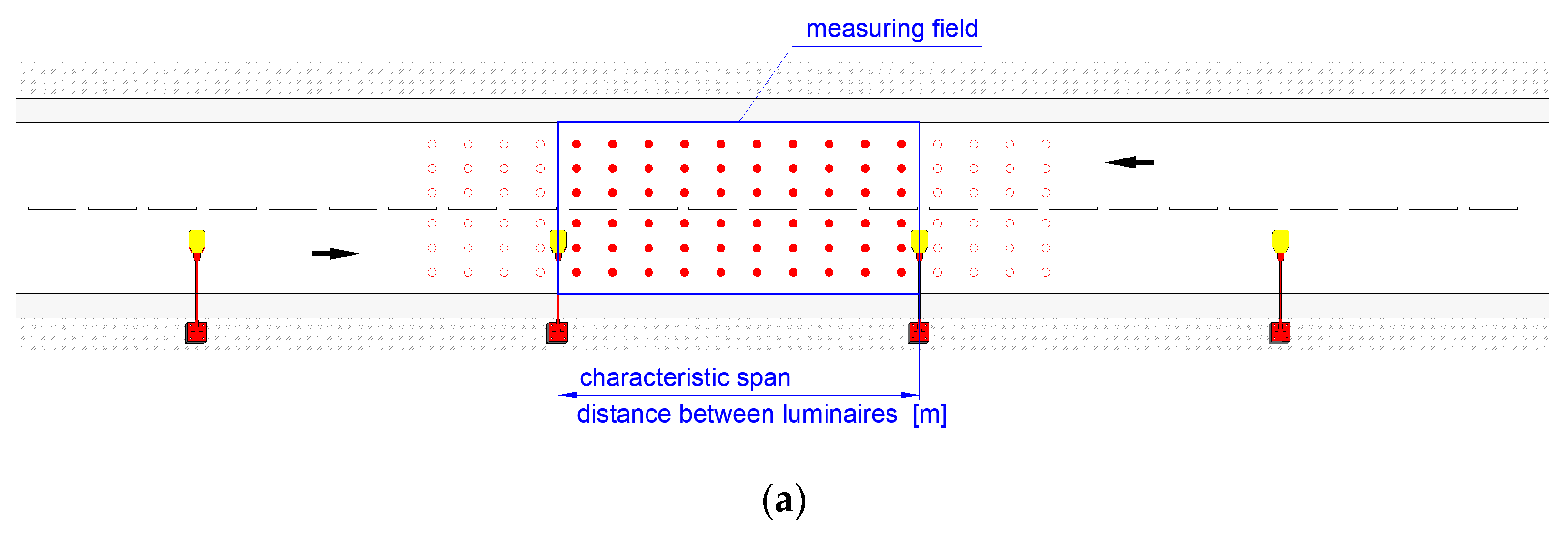
The layout of the lighting system along the carriageway is generally one-sided, and in some situations, where the carriageway is wider or has a different number of lanes in each direction, an opposite or alternate layout is chosen. At the installation design stage, identical and repeatable luminaire arrangements are usually adopted. The measurement area for the existing installation should be determined in accordance with the recommendations of the standard (Figure 1).
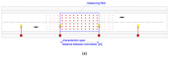

Figure 1.
Typical luminaire arrangements (a) single-sided, (b) opposite, (c) alternate.
It is important to remember that the design should be adapted to the existing street geometry, which is often complex and not obvious. In practice, available documentation or digital terrain map data Geographic Information System (GIS) can be used. For the entire street or analysed area, the surface areas should be determined individually for each field and on this basis the surface area of the entire illuminated road area should be determined.
One of the most important factors influencing electricity consumption is the operating time of the road lighting installation. For comparative calculations of the efficiency of the installation, a fixed operating time of 4000 h/year is assumed. It is recommended that the operation of artificial lighting be correlated with daylighting in terms of the illuminance required for a given lighting class. At sunset, the illuminance level is usually high, but quickly decreases. At sunrise, the situation is reversed. However, to determine the actual operating time of the installation, it is necessary to take into account the time of the year and the geographical latitude as well as the local conditions (e.g., individual switch-on and switch-off times of the installation).
Road lighting installations are often equipped with power reduction systems [42,43]. The recommended reduction of the lighting class level during the night time translates into a reduction of the power consumed by the lighting installation. Typical examples of daytime operating profiles for road lighting are given in the standard [12]. Typically, old-style installations with discharge light sources had single- or multi-stage power control. Modern luminaires using LED light sources have the possibility of fluent regulation of light flux in the full range of available power, so it is possible to precisely adjust the level of lighting to the current lighting needs of road users [44,45].
Measurement of Lighting Parameters
Controlling the condition of road or street lighting is a key factor in maintaining high lighting standards and determining the energy efficiency of installations. Currently, street lighting measurements occur mainly during the acceptance of newly designed installations. It is also necessary to check the condition of the lighting installations already in operation to maintain the assumed lighting parameters and to carry out possible maintenance. Based on the results, decisions can be made regarding the maintenance of luminaires or their replacement. Effective data acquisition on the condition of the lighting installation should involve the systematic establishment of lighting parameter levels. A substantive and systematic approach to assessing the actual condition can be used as a basis for making decisions about adjustment, maintenance or replacement of the installation.
There are limitations to the acquisition of photometric data, especially parameters related to the luminance of the road surface. The use of classical point luminance meter forces to apply the measurement procedure requires the operator to set up the instrument with precision and to allocate a significant time needed to perform the measurements for an assumed number of specific measurement points on the roadway [40,41]. Performing measurements according to the guidelines contained in the standard, especially in conditions of continuous road use, is difficult to achieve, and, in conditions of intensive urban traffic, practically impossible to carry out without closing a given thoroughfare and excluding sources of extraneous light. An alternative to luminance tests conducted with the point method is to conduct measurements with matrix meters [41] and further process the results in dedicated software. However, luminance measurements should be performed on a completely dry and clean surface, free from vehicles, pedestrians and any foreign objects that could distort the measurement. Measurements should not be made during moonlit nights or in bad weather conditions (fog, snow, wind, rising dust, etc.). According to the standard for luminance measurements, the most typical roadway section should be selected, avoiding sections where the measurement result may be distorted by external circumstances (e.g., shining advertisements or windows in buildings, light reflected from facades, etc.). According to the recommendations of the standard, calibrated measuring instruments should be used for the measurements. The instruments used for measurements should be corrected to the spectral curve of the relative sensitivity of a normal CIE photometric observer for photopic vision or should have spectral correction factors determined [41]. For temperature stabilisation of the luminaire, the measurements shall be made at least 0.5 h after the lamps have been switched on. In the case of testing installations consisting of new luminaires, to obtain nominal parameters, the installation should operate for at least 100 h
A number of factors can be identified that make it impossible or very difficult to determine the luminance parameters of the road surface, e.g., inadequate geometry of the measuring field, wet or dirty road surface, and presence of horizontal markings, presence of extraneous light from vehicles driving in the adjacent lane. The standard [39] provides for the possibility of converting the results of class M (luminance) to class C (illuminance), with knowledge of the reflectance of the road surface (three reference values).
Class C is intended for motor vehicle drivers and other road users, for conflict surfaces such as shopping streets, intersections of specified complexity, roundabouts and areas where vehicle queues form. Guidelines for the application of these classes are given in the standard [39]. These classes can also be applied to pedestrian and cycle pavements. The levels of lighting class C are defined by the parameters of the average value of illuminance and the overall uniformity of illumination UO (Table 1) [39]. In the context of lighting requirements for street and road lighting in class C [39], the following criteria are adopted:

Table 1.
The required illuminance levels for class C [39].
- (a)
- Average illuminance of the carriageway [lx]—the average illuminance should be calculated as the arithmetic mean of the illuminance obtained at grid points in the calculation or measurement field (Figure 1). The calculation or measurement field is the area between two consecutive luminaires [39];
- (b)
- The overall uniformity of roadway illuminance Uo. The uniformity of the illuminance should be calculated as the ratio of the lowest illuminance at each point in the calculation or measurement field to the average illuminance.
From the point of view of energy assessment, the parameter which binds the amount of light radiated from the luminaire and reaching the road surface is the illuminance parameter. Implementation of illuminance measurements by the methods described in the standard can be carried out in two ways: stationary measurement carried out in a grid of measurement points specified by the standard or dynamic measurements carried out in motion, while driving a vehicle equipped with an illuminance recording system and a GNSS receiver.
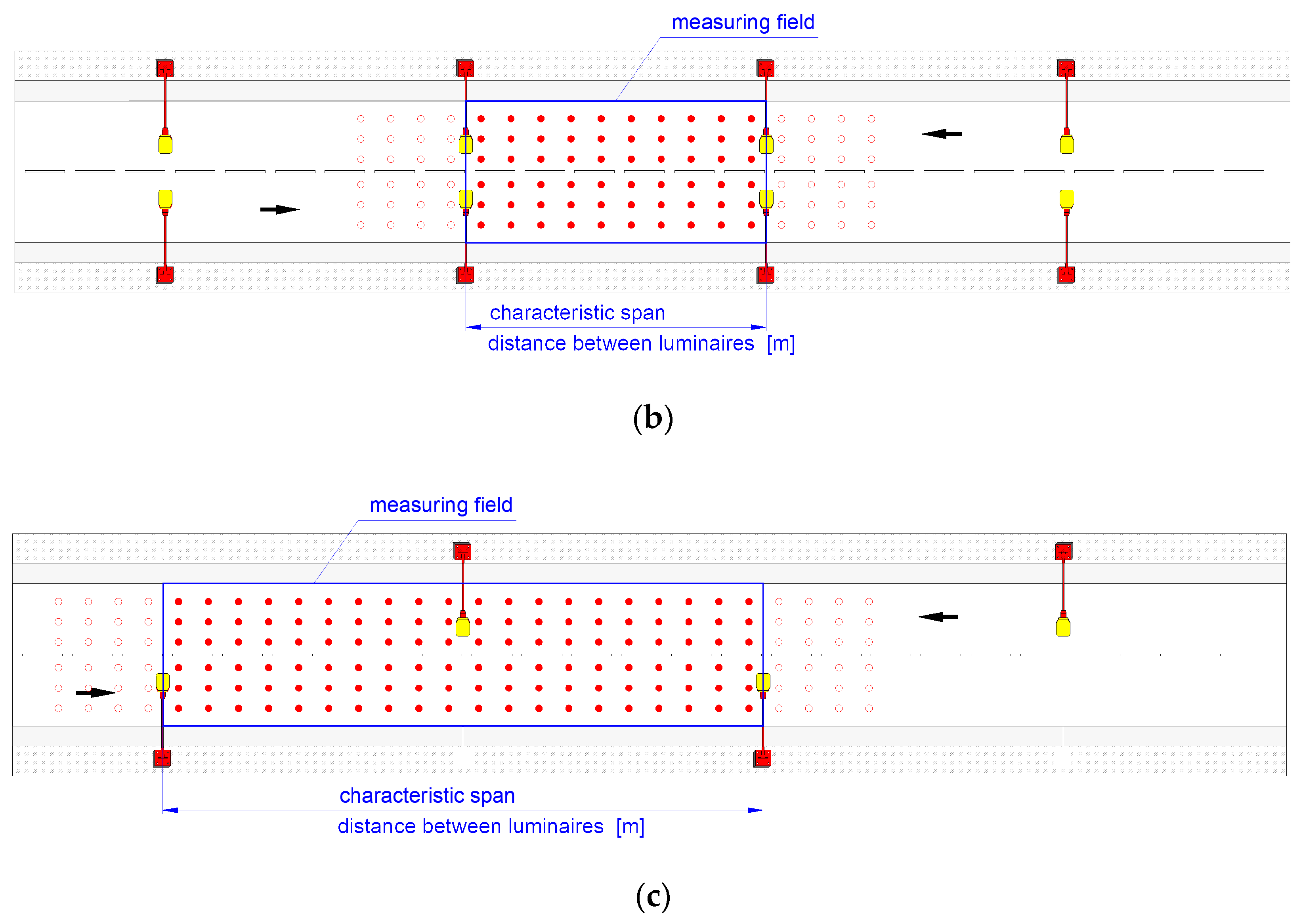
The first method is described in detail in the standard [40,41] and consists in the division of the tested road section into measurement fields, which are defined according to the street lighting solution and luminaire arrangement used on the road. The number of measurement points may vary significantly, from several dozen to several hundred depending on the geometrics of the road and the existing lighting system. The grid of measurement points is created using the relationships described in the standard (Formulas (1) and (2)) and their distribution is shown in Figure 2.
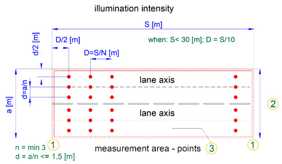
Figure 2.
Measuring points on the surface under consideration. Where: 1—luminaire, 2—width of the considered surface Wr, 3—design area. Markings according to the standard [40].
The illuminance measurement points shall be distributed evenly throughout the calculation field and their number shall be chosen as follows [40]:
- (a)
- In the longitudinal direction:where:
- D—distance between points in the longitudinal direction [m]
- S—distance between luminaires [m]
- N—number of design points in the longitudinal direction:
- For S ≤ 30 m, N = 10;
- For S ≥ 30 m, the smallest integer gives D ≤ 3 m.
- (b)
- In the transverse direction:where:
- d—distance between design points in the transverse direction [m]
- Wr—width of the roadway or surface under consideration [m].
- n—number of points in the transversal direction equal to 3 or more and being an integer d ≤ 1.5 m.
The grid of measurement points then allows the illuminance to be measured using a lux meter. In the stationary method, the measurement consists in recording the illuminance value for each point of the measurement grid. These measurements are taken at each of the grid points previously marked on the roadway (e.g., with temporary markers or chalk) using an illuminance meter. Both the large number of measurement points and the need to maintain an appropriate geometry make them so time-consuming that they can practically be carried out only for selected representation areas. Moreover, due to the reliability and accuracy of the measurement results as well as the necessity to maintain the safety of persons carrying out the measurements, the measurements should be made when the traffic on the surveyed road section is stopped. Therefore, these considerations significantly limit the possibility to survey main urban roads or expressways during their operation. This significantly hinders the identification of sections where lighting conditions are not met, and thus makes it difficult to identify energy indicators.
An alternative to the classical method is the dynamic method allowed by the standard [41], which enables the use of measuring vehicles to perform the measurements. The requirements for the measurement field and the minimum number of points in the measurement grid are independent of the method, while in the case of measurements carried out dynamically—from a moving vehicle, it is possible to perform measurements on a different measurement plane than the road surface. The standard lacks detailed guidelines describing the practical application of the dynamic method and correlations which coordinate the measured values. The standard only states the necessity of obtaining the same results as in the static method. Currently, there are no postmeasurement system solutions that have been fully validated by the results obtained in the static method taking into account all possible installation geometries and measurement scenarios.
3. Materials and Methods
3.1. Mobile Measurement System Concept
Mobile vehicle-based illuminance measurement systems have their origins in the late 1960s [46]. The problem of the first mobile illuminance measurement systems resulted from the limitations of the hardware and measurement capabilities of the illuminance sensors and hardware solutions for recording measurement data, which directly translated into a relatively low speed at which the measurement could be carried out. One of the initial errors in the conception of the measurement system was the location of the sensor and errors in the location of the measurement points. The idea of mounting the sensor behind the vehicle (Figure 2) resulted in a large measurement error due to the light sources being obscured by the vehicle body and the increased influence of extraneous light coming from other vehicles. Despite this, this type of system has been used in the United States to study road lighting conditions and attempts to correlate its condition with the occurrence of accidents. An attempt to solve the problem by changing the location of measuring sensors was made by the Zimmer team (Figure 3) [46]. They proposed mounting the sensors on a trailer pulled behind the vehicle. This solution eliminates the error resulting from the light sources being covered by the measuring vehicle. The key problem to be solved turned out to be the influence of the traffic lights of vehicles moving behind the measuring vehicle. Additional difficulties were found in obtaining a stable reading from the meters and the generation of errors by cars moving at high speeds in the adjacent lane, especially on motorways. Due to the limitations, this measurement system was used when vehicle traffic was temporarily stopped.
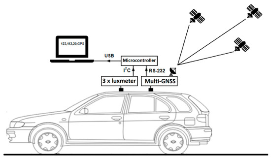
Figure 3.
Diagram of the author’s measurement system.
Nowadays, the concept of locating sensors on the roof of the vehicle enjoys the greatest popularity. This solution effectively eliminates the influence of the illumination coming from other vehicles (except for trucks) and street lights, advertisements, windows, and illuminated shop windows [47,48].
Extensive analyses on theoretical assumptions for the construction of the measuring system and the performance of measurements are included in the work by H. Zhou [49,50]. However, the unsolved issue is proving in practice the occurrence of the described relations and validation of the measurement system regardless of the road layout and street lighting system used. By locating the sensors on the vehicle roof, the measurement plane changes from the road surface to the height of the vehicle roof. Therefore, it is necessary to interpolate the results obtained on the plane of the road surface for which the requirements of the illumination value are presented in the standard. It is also possible to carry out lighting calculations for street lighting installations on the plane of the vehicle roof height in programs supporting lighting calculations (e.g., Dialux, Relux, Calculux).
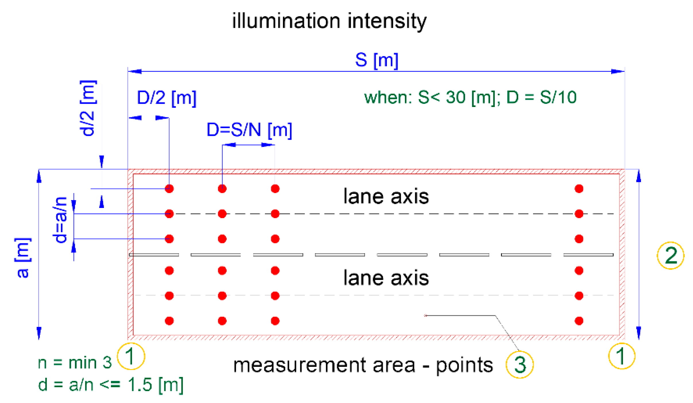
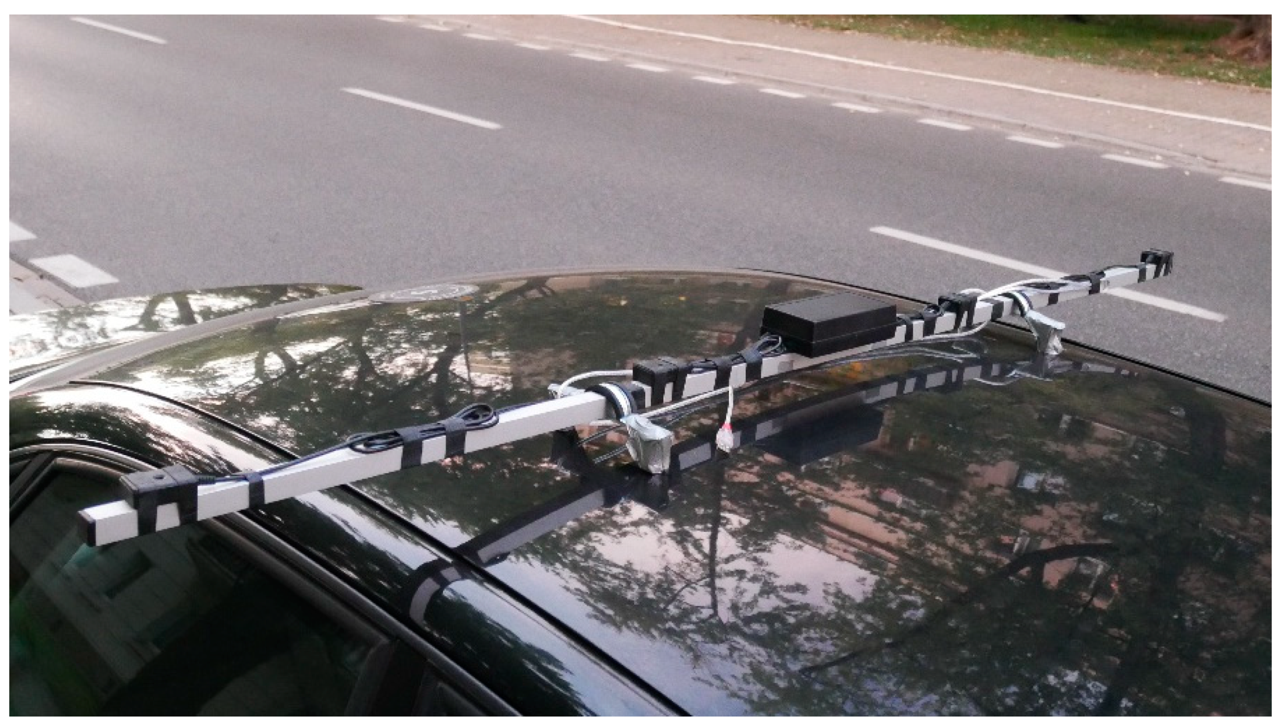
A mobile system for street lighting illuminance measurements has been built at the Faculty of Transport of the Warsaw University of Technology. The main elements of the designed system are three illumination sensors, GNSS and a microcontroller with a PC for recording and visualisation of the measurement data (Figure 3 and Figure 4).

Figure 4.
View of the proprietary measurement system on the vehicle roof.
The parallel measurement system realises the measurement by means of three (or if necessary four) illuminance sensors (Figure 4) distributed in geometry according to the instructions of the standard perpendicularly to the axis of the road lane. The use of three sensors allows to obtain the normative value of the rows and number of points of the measurement grid for one road lane in the transverse direction compliant with the requirements of the standard. The spacing between the illuminance sensors is adjusted to the width of the carriageway (in article b = 1 m, Figure 2). The designed system uses OPT3001 illuminance sensors with a spectral sensitivity close to the characteristics of human eyes and a postmeasurement frequency of 10 Hz. The measuring range is from 0.01 to 83 k (lx). The spectral match of the OPT3001 is 99%. The use of a GNSS receiver enables the location of measurement points on the road with a frequency of 10 Hz, while the microcontroller aggregates the measurement values and saves the data to a computer.
3.2. Description of the Measurement Field
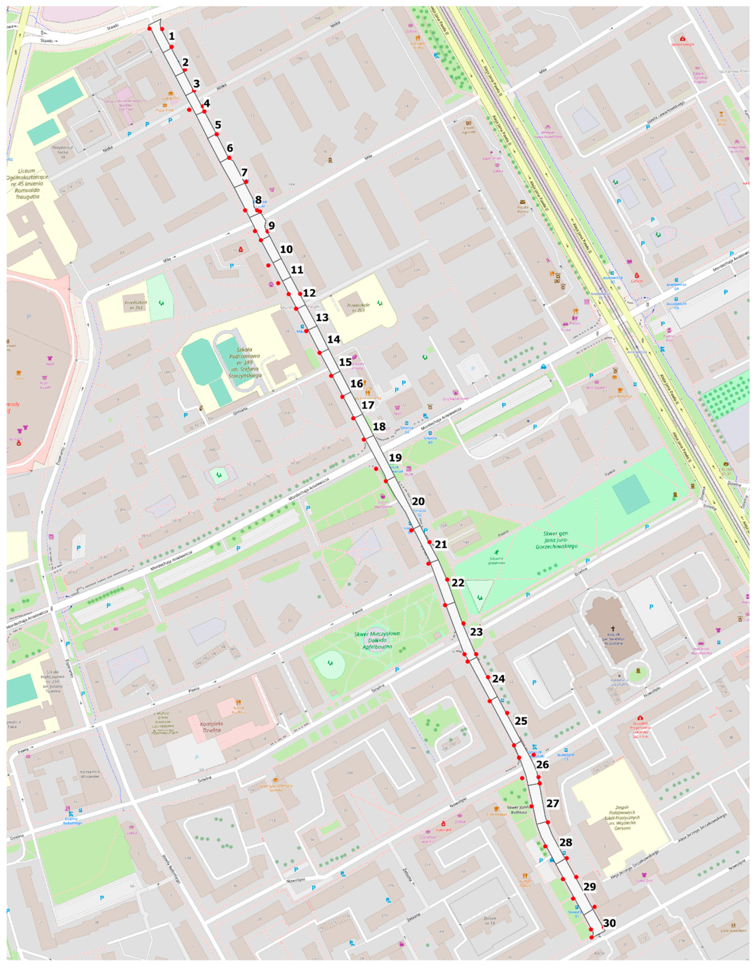
Tests on lighting parameters using a measurement system installed on a vehicle at a height of 1.5 m above the road surface, were carried out on the entire route of Smocza Street in Warsaw (Poland). The length of the street is 1025 m. The street was divided into 30 sections with the shape adapted to the road profile and with the length adjusted to the placement of poles specified in the requirements of the standard [40] (Figure 5). Geodetic data acquired in the open source geographic information system (QGIS environment) [51] was used to determine the surface area of the assessed areas. The measurement was carried out at a variable speed depending on road traffic conditions in the range of 10–50 km/h. In order to obtain a dense and even distribution of measuring points, constant and low speed driving should be implemented. However, this is not always possible in road traffic. Despite driving at variable speeds, the number of measurement points acquired in each measurement area exceeds the requirements of the standard. Data related to the location of luminaires and their technical parameters, including power was obtained on the basis of information provided by the road infrastructure manager ZDM in Warsaw in a digital file.
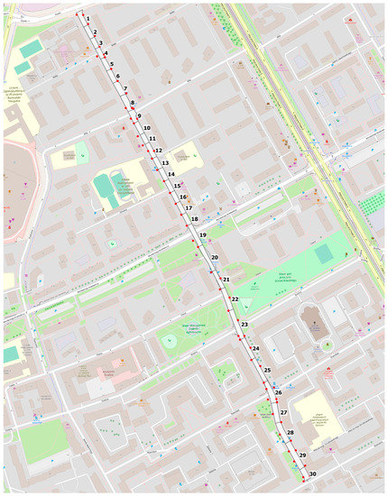
Figure 5.
Arrangement of measuring sections and luminaire locations.
Smocza Street in Warsaw is illuminated by a new lighting system with LED luminaires in one-sided and alternating settings. In a certain section, there is a change of setting of single-sided luminaires. There are nine pedestrian crossings illuminated with a system with two luminaires dedicated to lighting pedestrian crossings with asymmetrical light flux distribution.
4. Results
4.1. Empirical measurements
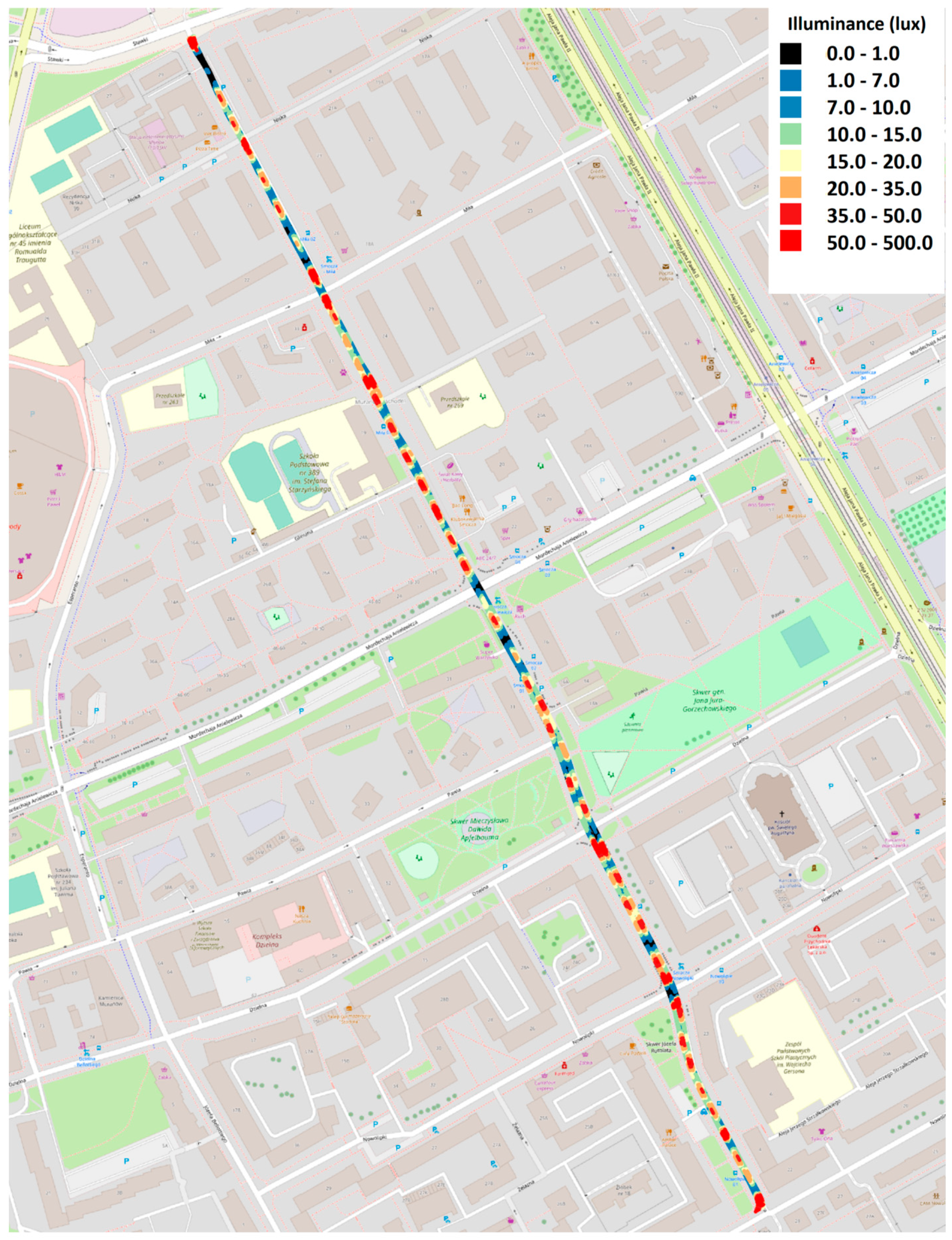
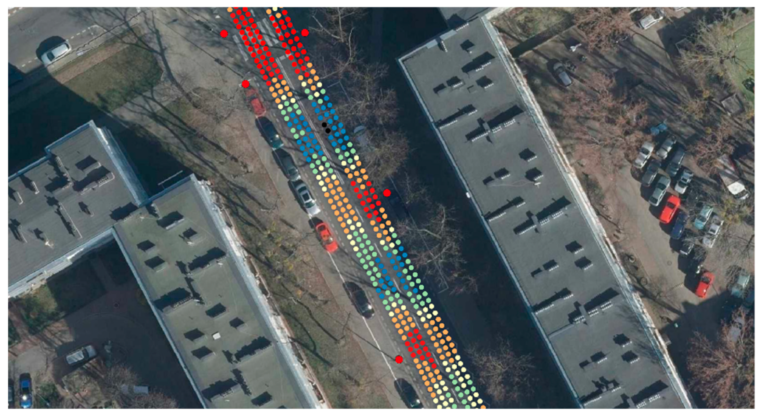
The illuminance measurements were carried out using the author’s system in two directions of traffic, with three rows of points in each lane. The distribution of illuminance throughout the street is shown in Figure 6.
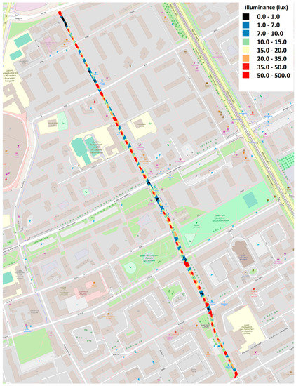
Figure 6.
Map of illumination measurements in the entire section of Smocza Street.
To relate the results of the tests carried out with the use of tools for measurements of motion, the results were related to static measurements carried out on a representative section marked with the number 24 in Figure 7. The results obtained do not indicate that a uniform and reproducible elongation distribution is obtained for the entire street. The non-uniformity of the distribution can be due to many factors such as: wear of the light source, incorrect positioning of the luminaire, dirty luminaire shade, etc. In this case, low illuminance levels are due to the presence of obstacles to light, tree crowns obscuring the lanterns, whereas very high illuminance levels are produced by auxiliary luminaires illuminating pedestrian crossings (Figure 7).
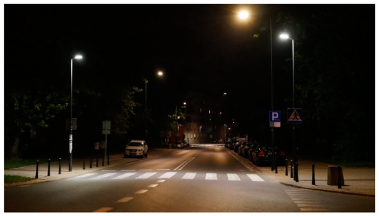
Figure 7.
View of a representative section, Section 24.
4.2. Selection of a Typical Representative Section
The measurement plane of the illuminance realised on the vehicle was at a height of 1.5 m. The standard plane of illuminance should be at the road height of 0.0 m. Therefore, the average values of illuminance should be recalculated. Based on manual comparative measurements made on a representative section, an attempt was made to determine a simplified correction factor on a representative section of the street.
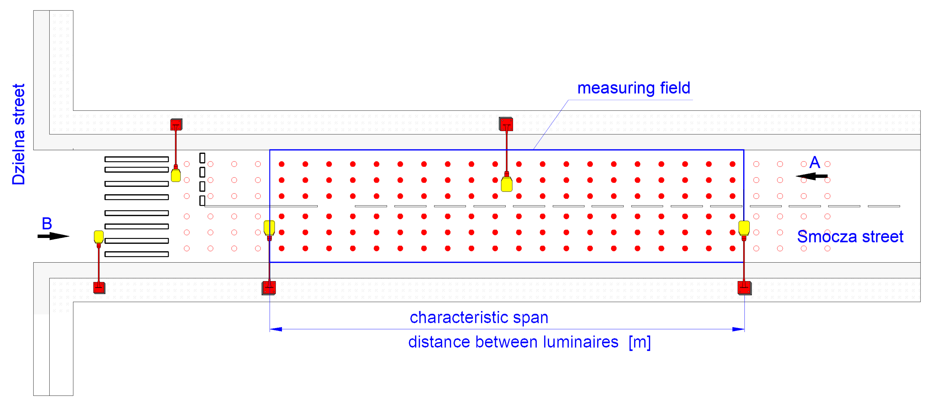
At the initial stage of works, a typical section of the street was selected. The representative measurement section was a one-lane two-way street with alternating street lighting system (Figure 8). The measurement area was 47 × 8 m. For such a defined area, 16 measurement points in the longitudinal direction and six in the transverse direction (three points per one traffic lane on the carriageway) can be assumed according to the recommendations of the standard. Obtaining a measurement for the entire carriageway surface means making passes in both directions. For the purposes of this study, direction A in the direction of Smocza St. towards Dzielna St. and the opposite direction B were assumed. For the purposes of the analysis, the research field was divided into two directions: A towards Dzielna St. and B as the opposite.
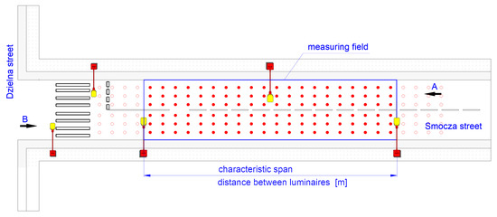
Figure 8.
Measurement field in Section 24.
First, two lanes of traffic were passed and the illuminance values were recorded using the measurement system Figure 9.

Figure 9.
Illuminance measurements on representative Section 24.
In the analysed representative area numbered 24, 264 measurement points were registered during driving measurements vehicle (plane 1.5 m) and the result of the average illuminance value was 18.718 lx with a standard deviation of 1.258 lx.
4.3. Stationary Measurements on a Representative Section
Stationary measurements of illuminance values on 1.5 m and 0.0 m planes were made with a classic A-class illuminance meter, in the grids of measurement points presented in Figure 10.
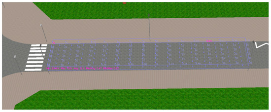
Figure 10.
Visualisation of representative Section 24 and the planes.
Table 2.
Measurements on the road surface 0.0 m.
Table 3.
Measurements on the road surface 1.5 m.
Podsumowanie calculations of illuminance parameters were performed for two planes 0.0 m and 1.5 m (Table 4).
Table 4.
Summary of calculation results of illuminance and energy indices of road lighting installation for 30 fields of Smocza street.
For the plane placed on the carriageway at a height of 0.0 m, an average illuminance value of 18.55 lx was obtained. For the plane located at the height of 1.5 m above the roadway, the average illuminance value of 22.259 lx was obtained. On the basis of the simplified lighting calculations performed for the analysed representative area number 24, a correction index j = 0.833 was established. It should be noted that this is a simplified calculation which does not take into account all aspects and may be subject to significant conversion errors, but for analysis of the energy intensity of the installation it is sufficient.
4.4. Results
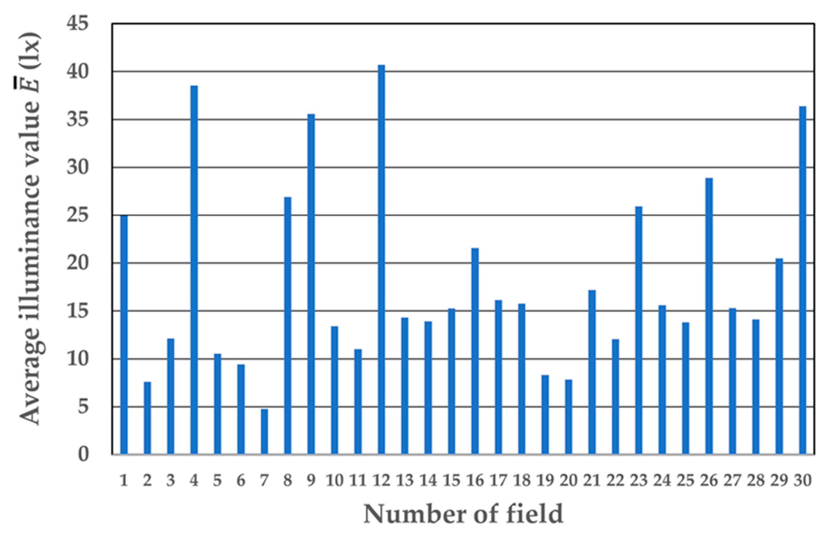
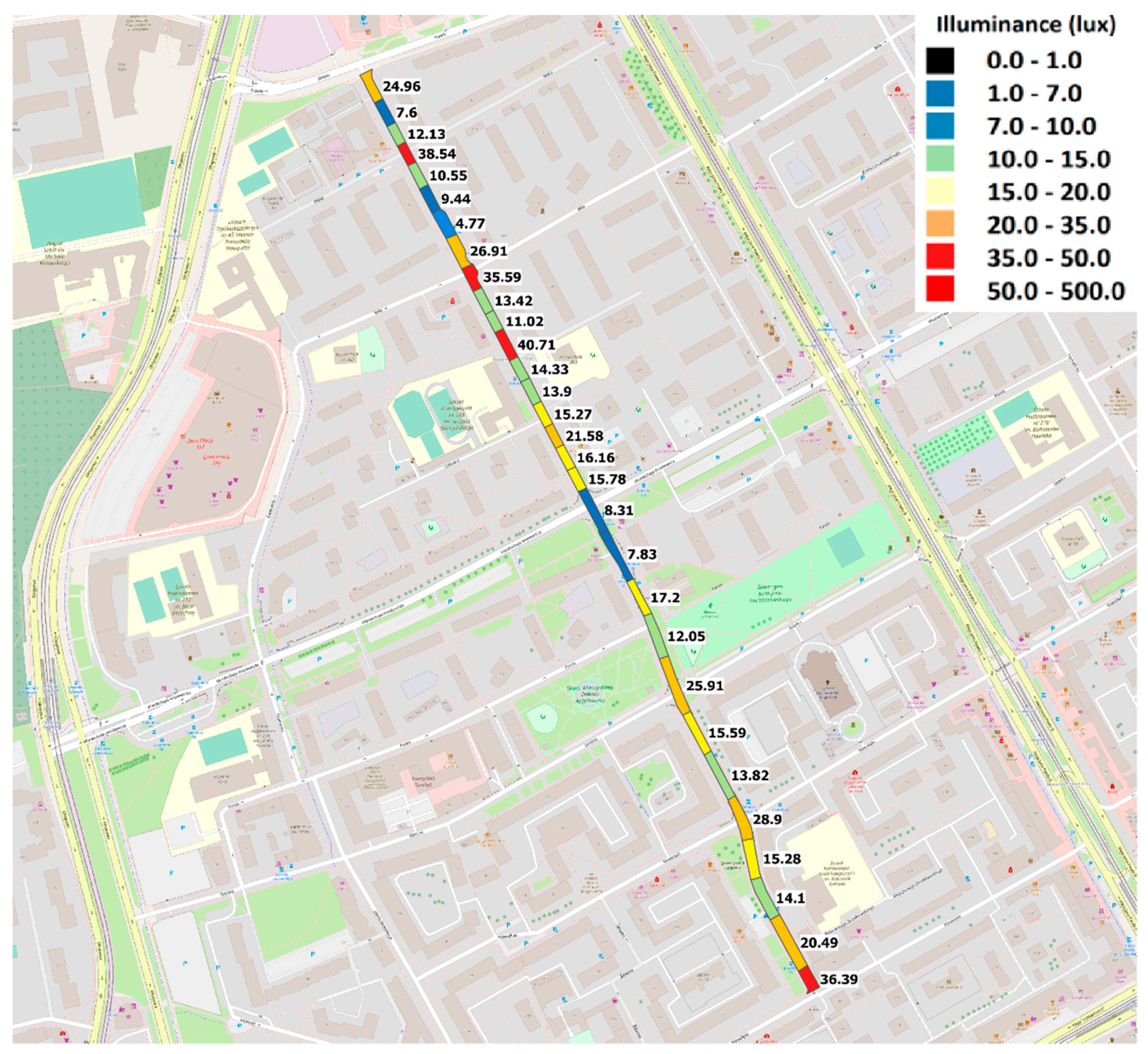
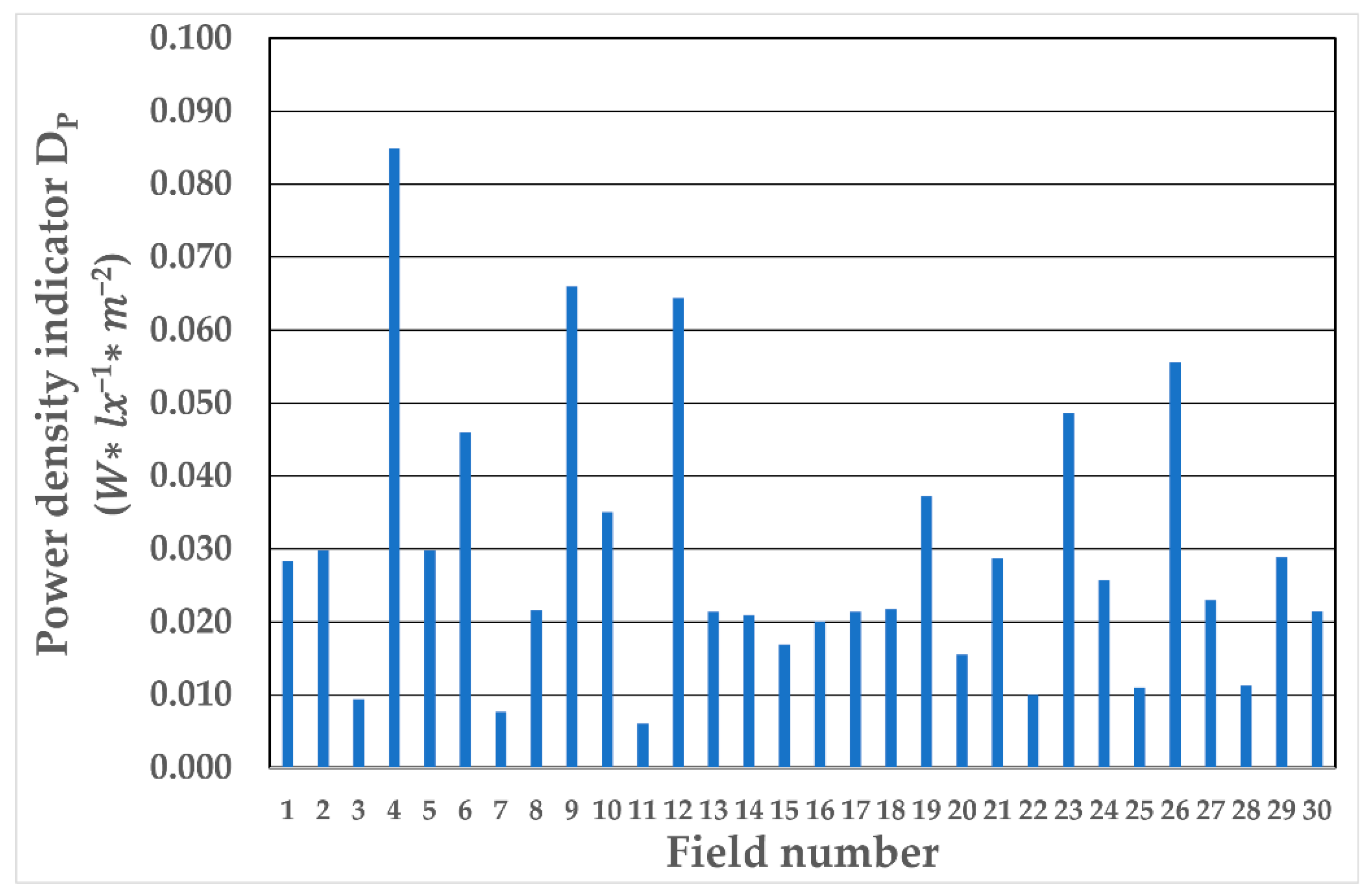
Table 4 presents the calculated values of the indicators of energy characteristics for individual measurement fields for the time of 4000 h of operation of the lighting installation per year, with the full power of luminaires (100%). On Figure 11, Figure 12, Figure 13, Figure 14, Figure 15 and Figure 16, the data have been plotted on Figure 11, Figure 13 and Figure 15 and on the map of the location of measuring fields Figure 12, Figure 14 and Figure 16.

Figure 11.
Mean illuminance values (lx) in the design fields.
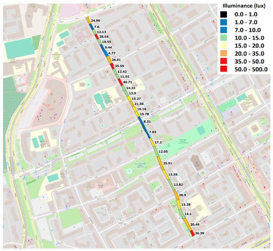
Figure 12.
Mean illuminance values (lx) in the calculation fields on the map.
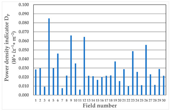
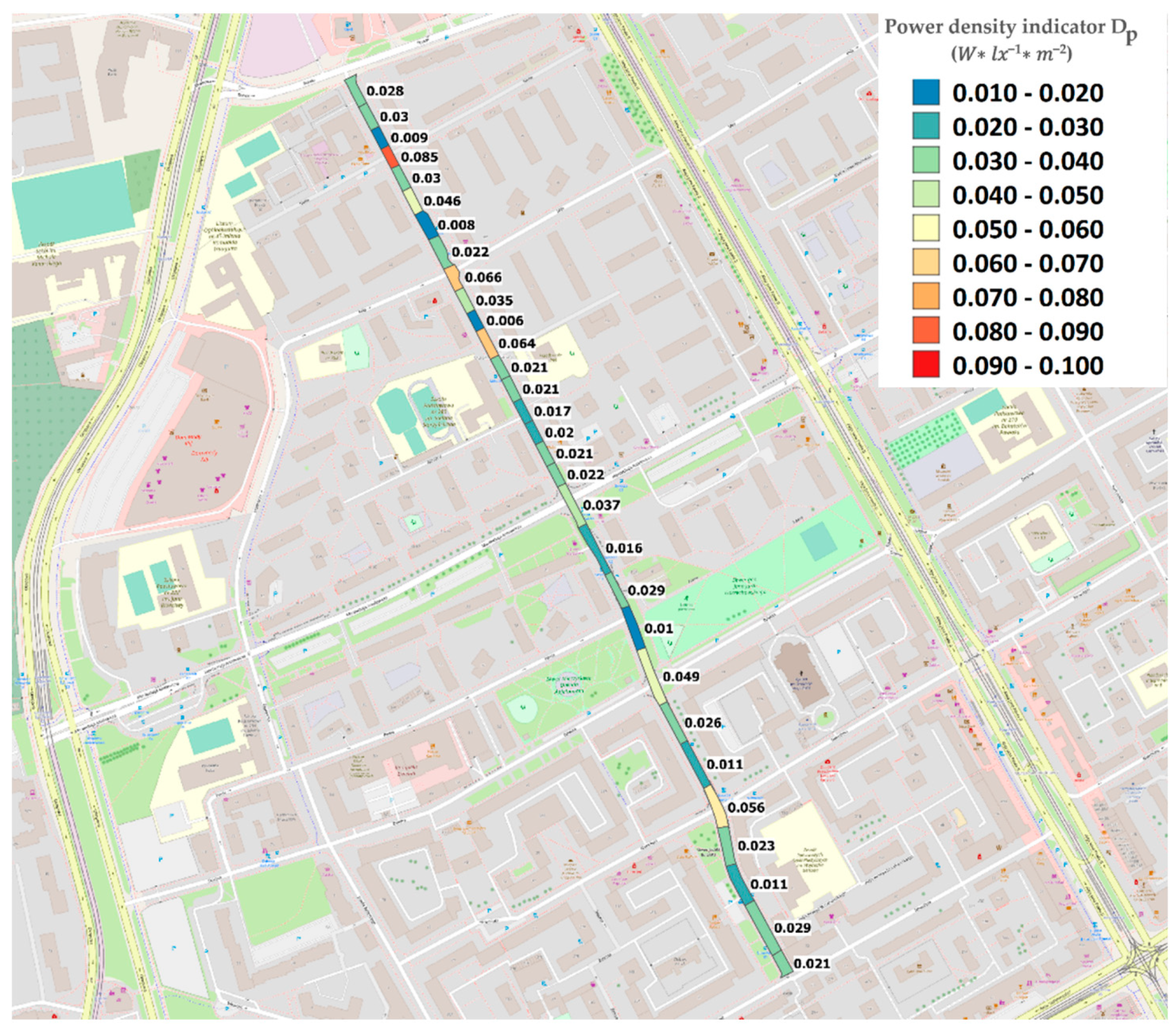
Figure 13.
Power density indicator DP () in the calculation field.
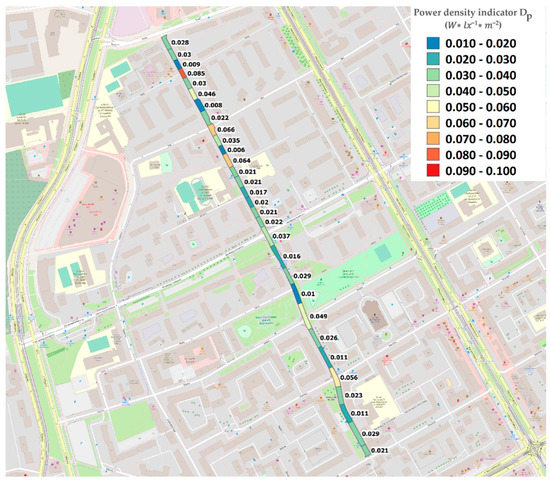
Figure 14.
Power density indicator DP () of calculated fields on the map.

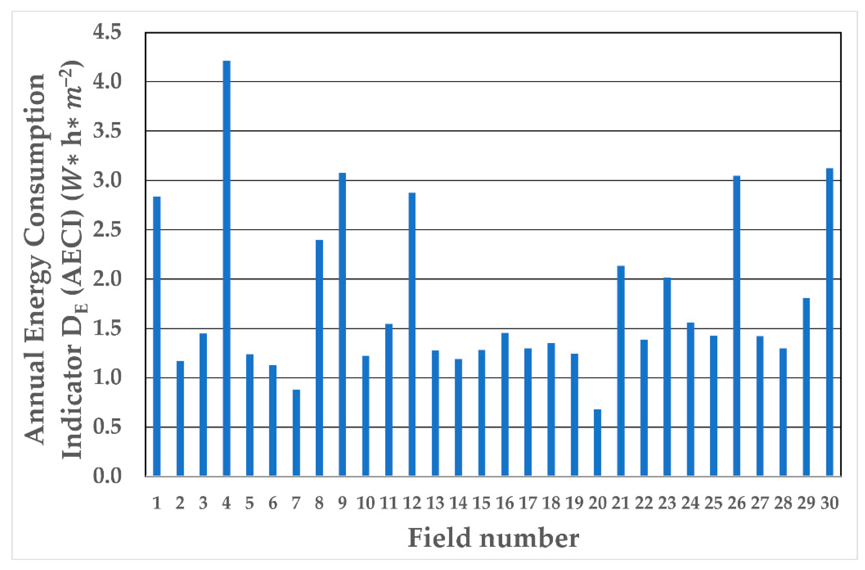
Figure 15.
DE (AECI) Annual Energy Consumption Indicator (W ∗ h ∗ m−2) in calculation fields.
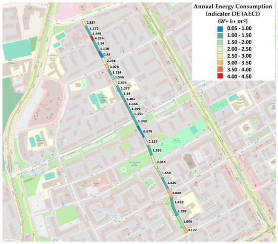
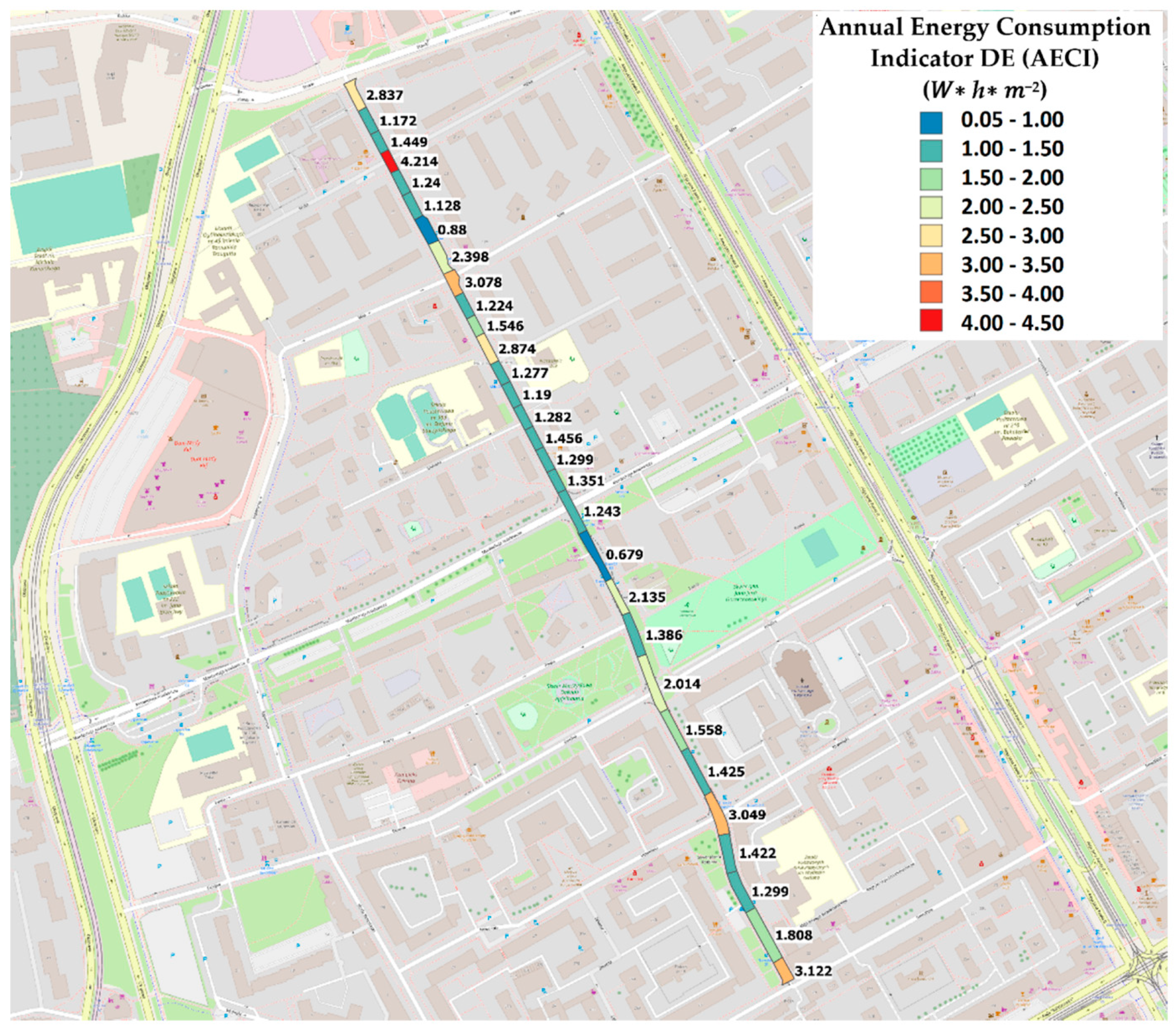
Figure 16.
DE (AECI) Annual Energy Consumption Indicator (W ∗ h ∗ m−2) in the calculation field on the map.
5. Discussion
As indicated in [52] and the [40] standard, road lighting installations should be designed and assessed for electricity consumption in a detailed and comprehensive manner. As demonstrated in the paper, conducting such an analysis is possible based on data acquired while driving a vehicle equipped with an appropriate metering system.
Mobile measurement systems can be used to acquire data on the condition of street lighting. The key in such systems is the unambiguous determination of the GPS position (standard geolocation solutions may be insufficient to obtain reliable information about the measurement point, so it is worth considering the use of RTK corrections [53]), appropriately fast measurement sensors and their optimal mounting on the vehicle. The choice of street lighting illuminance as the evaluation parameter makes it possible to use it in complex road systems where luminance measurement is impossible.
As shown on the street example given in the article, the choice of the representative field is difficult or even impossible for already operated installations with different configurations of columns and luminaires. In each of the analysed areas, different lighting conditions were obtained (Figure 11 and Figure 12), which fundamentally affects the determination of the efficiency parameters (Table 1, Figure 13, Figure 14, Figure 15 and Figure 16). Therefore, only testing of several areas of the whole street can give a reliable result of the lighting and energy parameters of the entire lighting installation. Using a simplified method consisting in taking one average value for the analysed instance, it can be shown that the obtained result differs from the values obtained as a sum of partial results for individual areas. For the street in question, the average illuminance value is 18.289 lux, the total illuminated area is 9825 m2, and the total power of the lighting installation is 4324 W. Therefore, assuming the final index was calculated as an average for the entire measured section, the result was DP = 0.024 (W ∗ lx−1 ∗ m−2), and it would be lower than the value obtained for the sum of the index Dp obtained for individual fields DP = 0.029 (W ∗ lx−1 ∗ m−2) (Table 4). The standard requirement [12] in terms of power density for the tested street with a width of up to 7 m of illuminated LED luminaires in class 3 is DP = 0.024 (W ∗ lx−1 ∗ m−2) and the typical value of the annual energy consumption index is DE = 1.5–1.6 (kWh·m−2). For the analysis of the street in 16 of the examined areas fulfilling the role of the DP indicator, and in 20 areas serving DE, analysing the value for this street and at the level of the 29th limit value DP = 0.02, the value of exceeding DP ∗ W ∗ lx−1 and 1.768 (kWh·m−2) (Table 2) normative values exceeded significantly, which will improve the results, and which follow from the completed lighting accessories for lighting. It almost lifts the binding power. The payment terms are based on the emission of light. The treetops obscured the light distribution to the road and reduced the value of the declining travel of lighting.
The recorded illuminance values allow to indicate the areas in which the lighting installation should be inspected (areas 2, 7, 19, 20). In this case, the reason for the poor illumination of the roadway surface is the presence of obstacles to the light, i.e., tree crowns adjacent to the roadway.
The j coefficient was determined on the basis of stationary illuminance measurements for a representative section, and the obtained value was adopted for the entire installation. The authors are aware of the use of a simplified approach, and this index will be the subject of further research. Further work will focus on improving the positioning and automatic determination of the measurement field, e.g., through lidar measurements. An additional aspect of the work requiring extension is the determination of the measurement error and determination of the influence of intrusive light, e.g., from other vehicles, advertisements, etc.
Determining the illumination level on the carriageway required changing the measuring plane. This issue is currently the subject of detailed study by the primary author’s team.
6. Conclusions
This paper presents preliminary research performed by a rapid method for evaluating the energy efficiency of a street lighting installation using geospatial information (GIS) and the results of illuminance measurements taken while a vehicle is driving in traffic.
The preliminary research presented in this paper allows the following final conclusions:
- -
- The lighting installations in operation vary significantly depending on the road geometry and terrain. Therefore, the whole road route cannot always be treated as a repeatable geometric system.
- -
- Use of classical methods of measurement of lighting parameters according to the standard [39,40] excludes the verification and determination of the energy parameters of the road in a short time.
- -
- Illumination measurement can be disturbed by lanterns from neighboring streets or traffic lights; placing the sensor on the roof of the car partially eliminates this problem.
- -
- It is necessary to continue research work on converting the measurement planes for different geometries of lighting installations (e.g., from 1.5 m to 0.0 m).
- -
- It is possible to measure lighting parameters and calculate energy indices both for the entire road system and for individual measurement sections, which is important from the point of view of selecting places where the assumed levels were not achieved.
- -
- It is possible to measure the illuminance level of the road while the vehicle is driving. Such measurements significantly accelerate the assessment of the state of illumination and determination of lighting class in accordance with the standard and allow to indicate the sections of underexposed or overexposed.
- -
- Obtained results of illuminance may be the basis for determining the average value of illuminance in a given area of the illuminated road.
- -
- Creation and sharing by infrastructure managers of geodetic data of lighting installations along with the power of installed luminaires (GIS) allows for quick identification of the power of luminaires installed in different sections of the road.
- -
- Based on the acquired data, it is possible to develop lighting maps and maps of energy indicators for entire roads or areas.
Determining the energy efficiency parameters of existing installations can be the basis for decisions on lighting upgrades or maintenance. Measurements on large urban areas or long road sections can be carried out by means of measurements in traffic. The results obtained confirm the usefulness of such systems, without detriment to the quality of the obtained results. These surveys should be carried out systematically over large areas. Lighting maps containing considerable amounts of measurement data may be created. Hence, the need to use IT tools supported by digital maps and GIS spatial data.
Additional benefits of conducting measurements of lighting parameters in road traffic besides electricity savings are: creation of area maps of lighting, cost savings associated with regular maintenance of equipment, regular inspection of equipment and flexible operational interventions, reduction of installation failure rate, possibility of effective lighting regulation and adjustment to current needs, increase in road traffic safety and improvement of safety of residents moving around the roads.
Author Contributions
Conceptualization, P.T., P.J., M.C.; methodology, P.T., P.J., M.C. and M.B.; software, P.T., P.J.; validation, P.T., P.J., M.C. and M.B.; formal analysis P.J. and P.T., investigation, P.T., P.J. and M.C.; resources, P.T., P.J., M.C. and M.B.; data curation, P.J. and P.T., writing—original draft preparation, P.T., P.J., M.C. and M.B.; writing—review and editing, P.T., P.J., M.C. and M.B.; visualization, P.T., P.J., M.C.; supervision, P.J. and P.T. All authors have read and agreed to the published version of the manuscript.
Funding
This research received no external funding.
Conflicts of Interest
The authors declare no conflict of interest.
References
- Bullough, J.D.; Donnell, E.T.; Rea, M.S. To Illuminate or Not to Illuminate: Roadway Lighting as it Affects Traffic Safety at Intersections. Accid. Anal. Prev. 2013, 53, 65–77. [Google Scholar] [CrossRef]
- Yannis, G.; Kondyli, A.; Mitzalis, N. Effect of Lighting on Frequency and Severity of Road Accidents. Proc. Inst. Civ. Eng.-Transp. 2013, 166, 271–281. [Google Scholar] [CrossRef]
- Jackett, M.; Consulting, J.; Frith, W. How Does the Level of Road Lighting Affect Crashes in New Zealand–A Pilot Study; Opus International Consultants: Lower Hutt, New Zealand, 2012. [Google Scholar]
- Kotulski, L. Smart Lighting–Nowe Spojrzenie na Oświetlenie Uliczne ... Systemy Dynamicznego Oświetlenia ulic–Przykład Rozwiązań Smart City. Available online: https://docplayer.pl/192892698-Smart-ligh-ng-nowe-spojrzenie-na-oswietlenie-uliczne-systemy-dynamicznego-oswietlenia-ulic-przyklad-rozwiazan-smart-city.html (accessed on 12 May 2021).
- Zissis, G.; Bertoldi, P.; Serrenho, T. Update on the Status of LED-Lighting World Market Since 2018; Publications Office of the European Union: Luxembourg, 2021; ISBN 978-92-76-27244-1. [Google Scholar]
- Traverso, M.; Donatello, S.; Moons, H.; Rodriguez Quintero, R.; Gama Caldas, M.; Wolf, O.; Van Tichelen, P.; Van Hoof, V.; Geerken, T. Revision of the EU Green Public Procurement Criteria for Street Lighting and Traffic Signals-Preliminary Report; Final Version EUR 28622 EN; Publications Office of the European Union: Luxembourg, 2017; ISBN 9789279690976. [Google Scholar]
- Quintero, R.R.; Garrido, C.V.-A.; Moons, H.; Caldas, M.G.; Wolf, O.; Skinner, I.; Van Grinsven, A.; ‘t Hoen, M.; van Essen, H. Revision of the EU Green Public Procurement Criteria for Transport; Publications Office of the European Union: Luxembourg, 2019; Volume 32, ISBN 9789279469640. [Google Scholar]
- EC Commission Regulation (EC) No 245/2009. Of 18 March 2009 Implementing Directive 2005/32/EC of the European Parliament and of the Council with Regard to Ecodesign Requirements for Fluorescent Lamps without Integrated Ballast, for High Intensity Discharge La. Off. J. Eur. Union 2009, 65, 60–87. [Google Scholar]
- EC Commission Regulation (EC) No 357/2010. Of 23 April 2010 Amending Regulation (EU) No 185/2010 of 4 March 2010 Laying Down Detailed Measures for the Implementation of the Common Basic Standards on Aviation Security. Off. J. Eur. Union 2010, 72, 10–11. [Google Scholar]
- Parliament, T.H.E.E.; Council, T.H.E.; The, O.F.; Union, E. Directive 2011/83/EU of the European Parliament and of the Council. Off. J. Eur. Union 2011, 8, 260–284. [Google Scholar]
- Oświetlenie Uliczne-Sektor Efektywności Energetycznej. Dobre Praktyki PPP. Available online: https://www.ppp.gov.pl/dobre-praktyki/ (accessed on 12 May 2021).
- EN 13201-5:2015-Road Lighting-Part 5: Energy Performance Indicators. 2015. Available online: https://infostore.saiglobal.com/preview/is/en/2015/i.s.en13201-5-2015.pdf?sku=1843914 (accessed on 12 May 2021).
- Ernst, S.; Kotulski, L.; Lerch, T.; Rad, M.; Sȩdziwy, A.; Wojnicki, I. Calculating Reactive Power Compensation for Large-Scale Street Lighting. Int. Conf. Comput. Sci. 2020, 12138, 538–550. [Google Scholar] [CrossRef]
- Pracki, P.; Wiśniewski, A.; Czyżewski, D.; Krupiński, R.; Skarżyński, K.; Wesołowski, M.; Czaplicki, A. Strategies Influencing Energy Efficiency of Lighting Solutions. Bull. Polish Acad. Sci. Tech. Sci. 2020, 68, 711–719. [Google Scholar] [CrossRef]
- Doulos, L.T.; Sioutis, I.; Kontaxis, P.; Zissis, G.; Faidas, K. A Decision Support System for Assessment of Street Lighting Tenders Based on Energy Performance Indicators and Environmental Criteria: Overview, Methodology and Case Study. Sustain. Cities Soc. 2019, 51, 101759. [Google Scholar] [CrossRef]
- Culver, S. Energy Efficiency in Ironing. Text. Rent. 2009, 92, 46–47. [Google Scholar]
- Light Naturally. Energy Efficiency Performance Requirements for Road Lighting Designs and Luminaires. Available online: https://www.energyrating.gov.au/sites/default/files/documents/StreetlightEEreport2014FINAL_0.pdf (accessed on 12 May 2021).
- Sȩdziwy, A.; Kotulski, L. Towards Highly Energy-Efficient Roadway Lighting. Energies 2016, 9, 263. [Google Scholar] [CrossRef]
- Wojnicki, I.; Kotulski, L. Improving Control Efficiency of Dynamic Street Lighting by Utilizing the Dual Graph Grammar Concept. Energies 2018, 11, 402. [Google Scholar] [CrossRef] [Green Version]
- Wojnicki, I.; Kotulski, L.; Sędziwy, A.; Ernst, S. Application of Distributed Graph Transformations to Automated Generation of Control Patterns for Intelligent Lighting Systems. J. Comput. Sci. 2017, 23, 20–30. [Google Scholar] [CrossRef]
- Jägerbrand, A.K. Synergies and Trade-Offs Between Sustainable Development and Energy Performance of Exterior Lighting. Energies 2020, 13, 2245. [Google Scholar] [CrossRef]
- Klaassen, N.; Scheepens, A.; Flipsen, B.; Vogtlander, J. Eco-Efficient Value Creation of Residential Street Lighting Systems by Simultaneously Analysing the Value, the Costs and the Eco-Costs during the Design and Engineering Phase. Energies 2020, 13, 3351. [Google Scholar] [CrossRef]
- Hermoso-Orzáez, M.J.; Lozano-Miralles, J.A.; Lopez-Garcia, R.; Brito, P. Environmental Criteria for Assessing the Competitiveness of Public Tenders with the Replacement of Large-Scale LEDs in the Outdoor Lighting of Cities as a Key Element for Sustainable Development: Case Study Applied with PROMETHEE methodology. Sustainability 2019, 11, 5982. [Google Scholar] [CrossRef] [Green Version]
- Doulos, L.; Tsangrassoulis, A.; Topalis, F.V. Multi-Criteria Decision Analysis To Select The Optimum Position and Proper Field of View of a Photosensor. Energy Convers. Manag. 2014, 86, 1069–1077. [Google Scholar] [CrossRef]
- Benito, B.; Guillamón, M.D.; Martínez-Córdoba, P.J. Determinants of Efficiency Improvement in the Spanish Public Lighting Sector. Util. Policy 2020, 64, 101026. [Google Scholar] [CrossRef]
- Lobão, J.A.; Devezas, T.; Catalão, J.P.S. Energy Efficiency of Lighting Installations: Software Application and Experimental Validation. Energy Rep. 2015, 1, 110–115. [Google Scholar] [CrossRef] [Green Version]
- Jägerbrand, A.K. LED (Light-Emitting Diode) Road Lighting in Practice: An Evaluation of Compliance with Regulations and Improvements for Further Energy Savings. Energies 2016, 9, 357. [Google Scholar] [CrossRef] [Green Version]
- Lipnicky, L.; Gasparovsky, D.; Dubnicka, R. Influence of the Calculation Grid Density to the Selected Photometric Parameters for Road Lighting. In Proceedings of the 2016 IEEE Lighting Conference of the Visegrad Countries (Lumen V4), Karpacz, Poland, 13–16 September 2016; pp. 1–4. [Google Scholar] [CrossRef]
- Leśko, M.; Różowicz, A.; Wachta, H.; Różowicz, S. Adaptive Luminaire with Variable Luminous Intensity Distribution. Energies 2020, 13, 721. [Google Scholar] [CrossRef] [Green Version]
- Martirano, L.; Ruvio, A.; Manganelli, M.; Lettina, F.; Venditti, A.; Zori, G. High Efficiency Lighting Systems with advanced Controls. IEEE Trans. Ind. Appl. 2021. [Google Scholar] [CrossRef]
- Maksimainen, M.; Vaaja, M.T.; Kurkela, M.; Virtanen, J.P.; Julin, A.; Jaalama, K.; Hyyppä, H. Nighttime Mobile Laser Scanning and 3D Luminance Measurement: Verifying the Outcome of Roadside Tree Pruning with Mobile Measurement of the road Environment. ISPRS Int. J. Geo-Inf. 2020, 9, 455. [Google Scholar] [CrossRef]
- Boyce, P.R. Light, lighting and human health. Light. Res. Technol. 2021. [Google Scholar] [CrossRef]
- Kyuchukov, T. Light Pollution-’Borders’ of Lighting Design. In Proceedings of the 2019 Second Balkan Junior Conference on Lighting (Balkan Light Junior), Plovdiv, Bulgaria, 19–21 September 2019; pp. 1–5. [Google Scholar] [CrossRef]
- Lim, H.S.; Ngarambe, J.; Kim, J.T.; Kim, G. The Reality of Light Pollution: A Field Survey for the Determination of Lighting Environmental Management Zones in South Korea. Sustainability 2018, 10, 374. [Google Scholar] [CrossRef] [Green Version]
- Jägerbrand, A.K. Effects of LED lighting on Animals and in the Natural Environment and Recommendations to Minimize the Impact. In Proceedings of the 8th Professional Lighting Design Convention, Rotterdam, The Netherlands, 23–26 October 2019; pp. 98–99. [Google Scholar]
- McNaughton, E.J.; Beggs, J.R.; Gaston, K.J.; Jones, D.N.; Stanley, M.C. Retrofitting Streetlights with LEDs has Limited Impacts on Urban Wildlife. Biol. Conserv. 2021, 254, 108944. [Google Scholar] [CrossRef]
- Commission Internationale de L’éclairage. Lighting of Roads for Motor and Pedestrian Traffic; International Commission on Illumination: Vienna, Austria, 2010; pp. 1–8. [Google Scholar]
- CEN/TR 13201-1:2014—Road lighting—Part 1: Guidelines on Selection of Lighting. 2014. Available online: https://standards.iteh.ai/catalog/standards/cen/69d92ac3-b17c-4208-bb2b-fab9175bb2a4/cen-tr-13201-1-2014 (accessed on 12 May 2021).
- EN 13201-2:2015-Road lighting—Part 2: Performance Requirements. 2015. Available online: https://standards.iteh.ai/catalog/standards/cen/af4239ad-70ec-48d2-bf4c-fba1a373d3ba/en-13201-2-2015 (accessed on 12 May 2021).
- EN 13201-3:2015-Road lighting—Part 3: Calculation of Performance. 2015. Available online: https://standards.iteh.ai/catalog/standards/cen/3b3f153c-192f-486e-ba81-d0a6dbb114c4/en-13201-3-2015 (accessed on 12 May 2021).
- EN 13201-4:2015-Road lighting—Part 4: Methods of Measuring Lighting Performance. 2015. Available online: https://standards.iteh.ai/catalog/standards/cen/7f260a69-7e63-4bdd-9282-39f4cc21a815/en-13201-4-2015 (accessed on 12 May 2021).
- Jes, M.; Gago-calder, A. Energy Efficiency and Sustainable Lighting-a Bet for the Future; IntechOpen: London, UK, 2020; ISBN 9781789859591. [Google Scholar]
- Sánchez Sutil, F.; Cano-Ortega, A. Smart Public Lighting Control and Measurement System Using Lora Network. Electronics 2020, 9, 124. [Google Scholar] [CrossRef] [Green Version]
- Torzewicz, T.; Baran, K.; Raszkowski, T.; Samson, A.; Wachta, H.; Napieralski, A. Compact Thermal Modelling of Power LED Light Sources. In Proceedings of the 2017 IEEE 30th International Conference on Microelectronics (MIEL), Nis, Serbia, 9–11 October 2017; pp. 157–160. [Google Scholar] [CrossRef]
- Baran, K.; Rózowicz, A.; Wachta, H.; Rózowicz, S. Modeling of selected lighting parameters of LED panel. Energies 2020, 13, 3583. [Google Scholar] [CrossRef]
- Zimmer, R.A. A mobile illumination evaluation system. Transp. Res. Rec. J. Transp. Res. Board 1988, 68–73. Available online: http://onlinepubs.trb.org/Onlinepubs/trr/1988/1172/1172-008.pdf (accessed on 12 May 2021).
- Johnson, M.; Fabregas, A.; Wang, Z.; Katkoori, S.; Lin, P.S. Embedded system design of an advanced illumination measurement system for highways. In Proceedings of the 2014 IEEE International Systems Conference Proceedings, Ottawa, ON, Canada, 31 March–3 April 2014; pp. 579–586. [Google Scholar] [CrossRef]
- Gibbons, R.B.; Meyer, J. Development of a Mobile Measurement System for Roadway Lighting. 2018. Available online: https://vtechworks.lib.vt.edu/bitstream/handle/10919/81535/NSTSCE_RLMMS_Final.pdf?sequence=1#:~:text=This%20system%2C%20the%20Roadway%20Lighting,and%20mounted%20on%20any%20vehicle.&text=The%20system%20also%20uses%20two,color%20camera%20for%20scene%20evaluation. (accessed on 12 May 2021).
- Zhou, H.; Pirinccioglu, F.; Hsu, P. A new Roadway Lighting Measurement System. Transp. Res. Part C Emerg. Technol. 2009, 17, 274–284. [Google Scholar] [CrossRef]
- Zhou, H.; Hsu, P.; Lin, P. A New Method to Evaluate Roadway Lighting Systems and Its Safety Effects. In Proceedings of the ITE 2010 Annual Meeting and Exhibit, Vancouver, Canada, 8–11 August 2010; p. AB10H283. [Google Scholar]
- QGIS A Free and Open Source Geographic Information System. Available online: https://www.qgis.org/en/site/ (accessed on 12 May 2021).
- Commission Staff Working Documen Commission Staff Working Document Eu Gpp Green Public Procurement Criteria for Road Lighting and Traffic Signals. Available online: https://ec.europa.eu/environment/gpp/pdf/toolkit/181210_EU_GPP_criteria_road_lighting.pdf (accessed on 12 May 2021).
- Rychlicki, M.; Kasprzyk, Z.; Rosiński, A. Analysis of Accuracy and Reliability of Different Types of GPS Receivers. Sensors 2020, 20, 6498. [Google Scholar] [CrossRef] [PubMed]


Publisher’s Note: MDPI stays neutral with regard to jurisdictional claims in published maps and institutional affiliations. |
© 2021 by the authors. Licensee MDPI, Basel, Switzerland. This article is an open access article distributed under the terms and conditions of the Creative Commons Attribution (CC BY) license (https://creativecommons.org/licenses/by/4.0/).