
Dual-Band RF Wireless Power Transfer System with a Shared-Aperture Dual-Band Tx Array Antenna


Abstract
:1. Introduction
2. Implementation of a Dual-Band RF Wireless Power Transfer (WPT) System
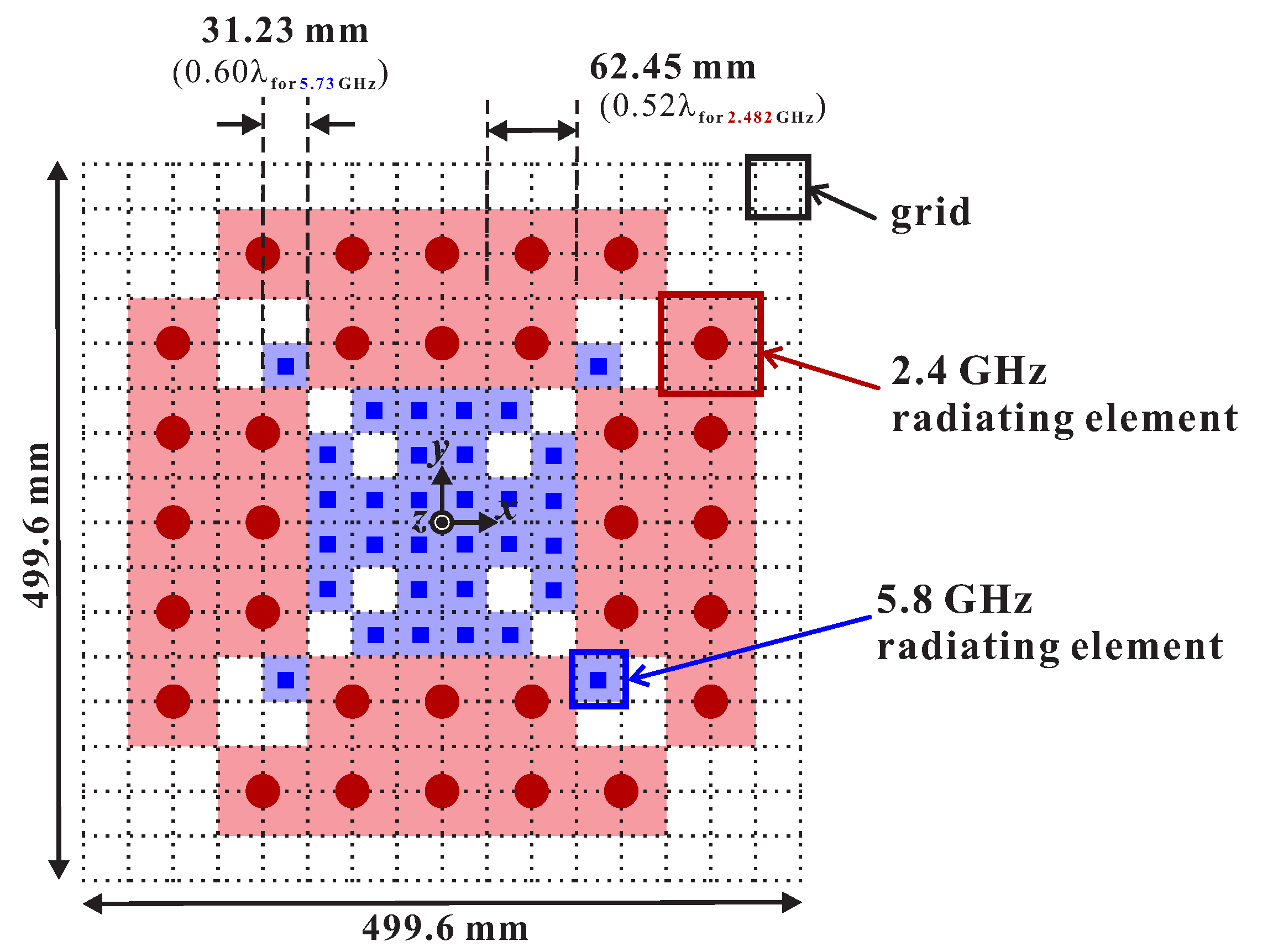
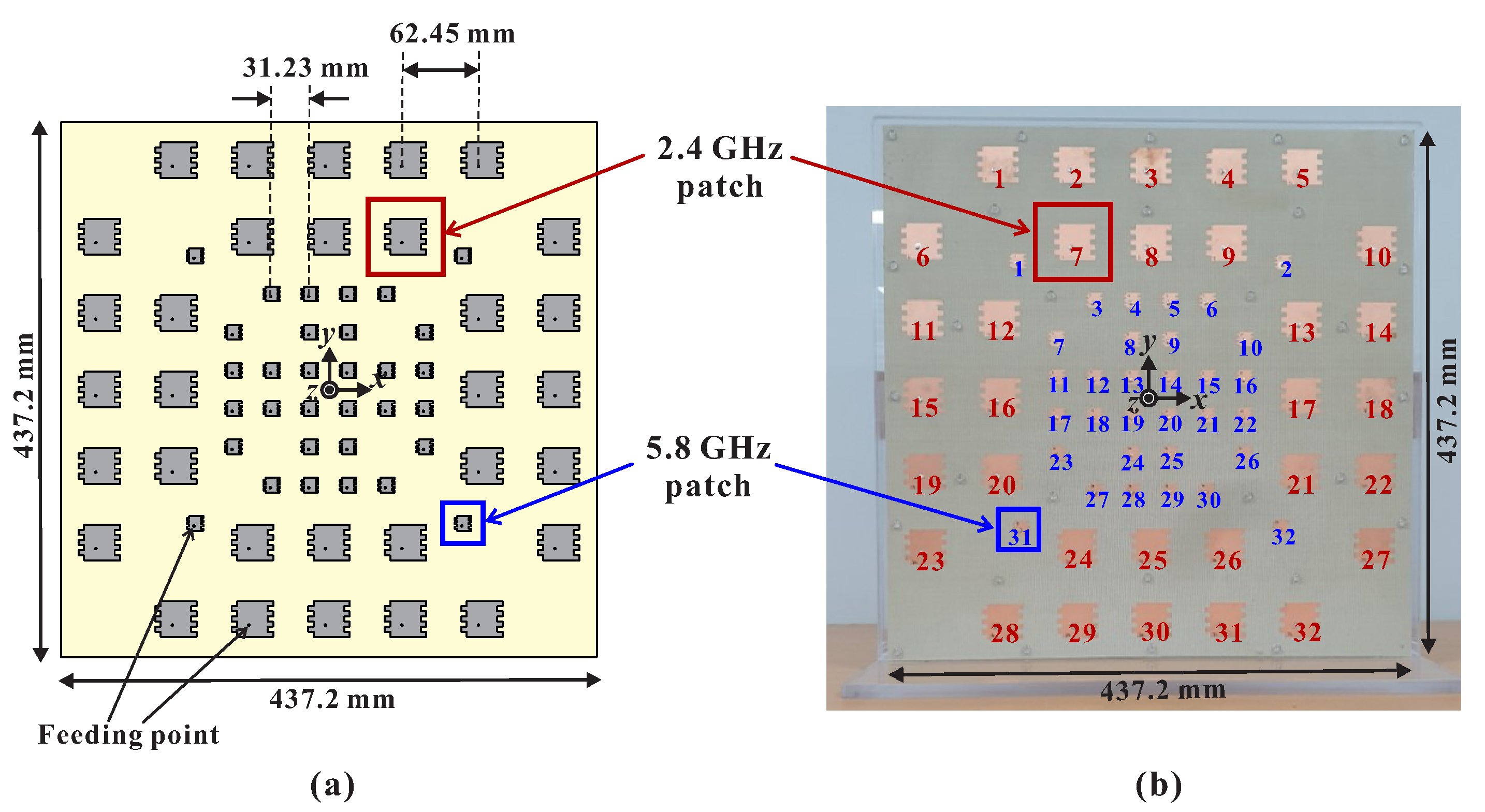
2.1. Design of a Shared-Aperture Dual-Band Tx Array Antenna
2.2. Implementation of the Dual-Band Tx System
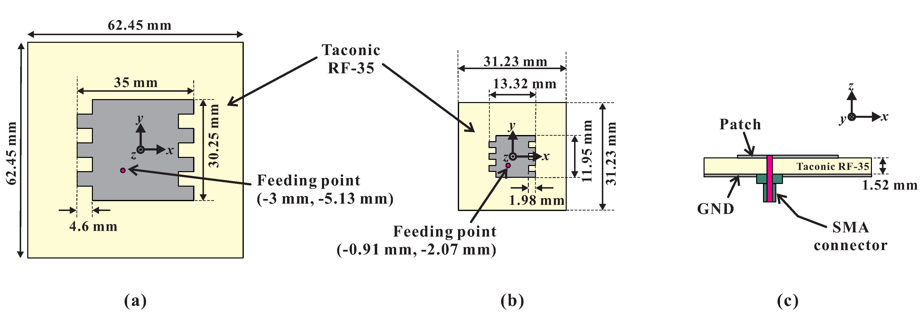
2.3. Design of the Rx Antennas
2.3.1. 2.4 GHz Patch
2.3.2. 5.8 GHz Patch
2.3.3. Dual-Band (2.4 and 5.8 GHz) Patch
3. Experimental Results of RF Wireless Power Transmission
3.1. Single-Band RF WPT Experiment
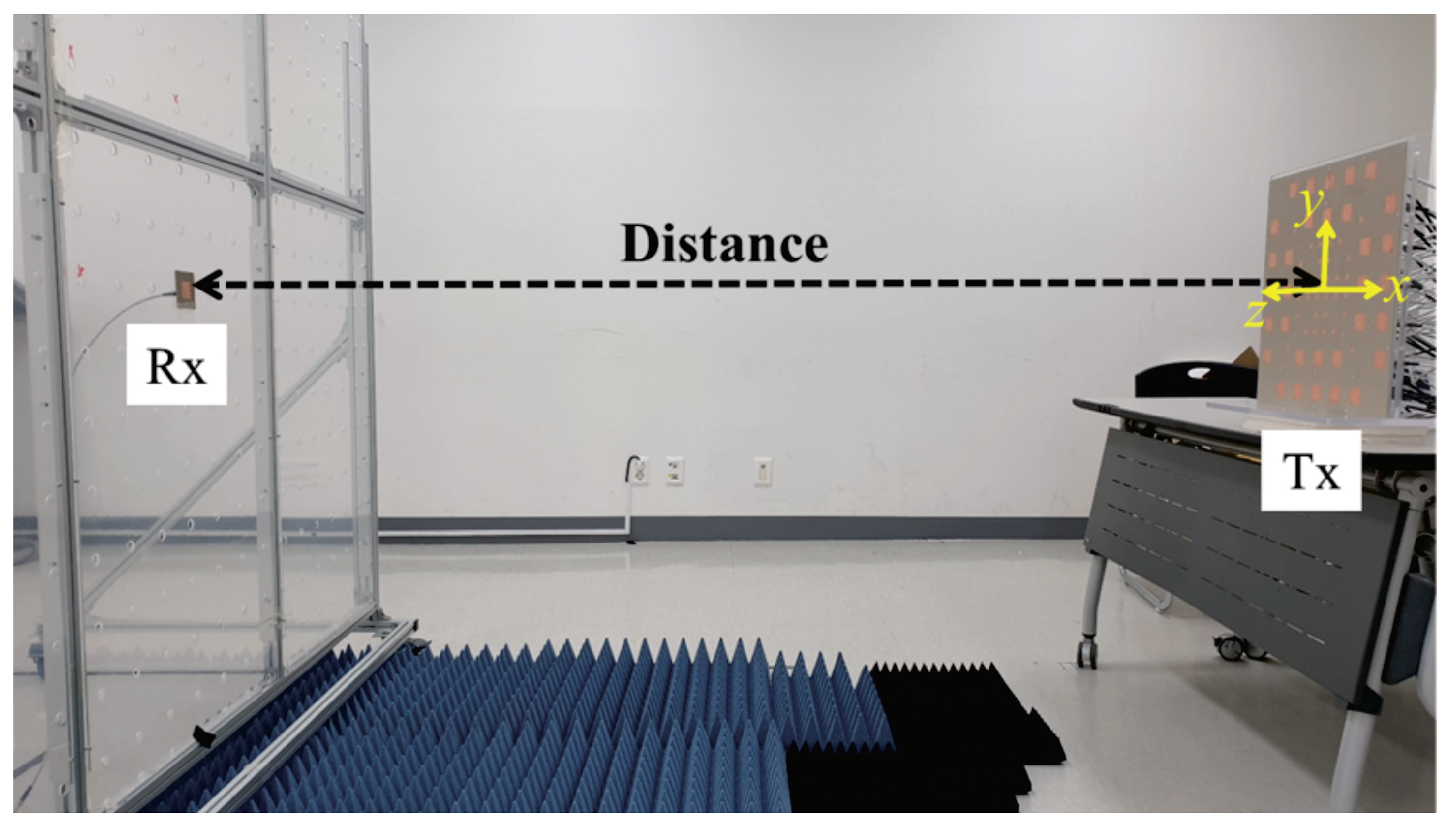
3.1.1. WPT Experiment (1): Varying the Transmission Distance
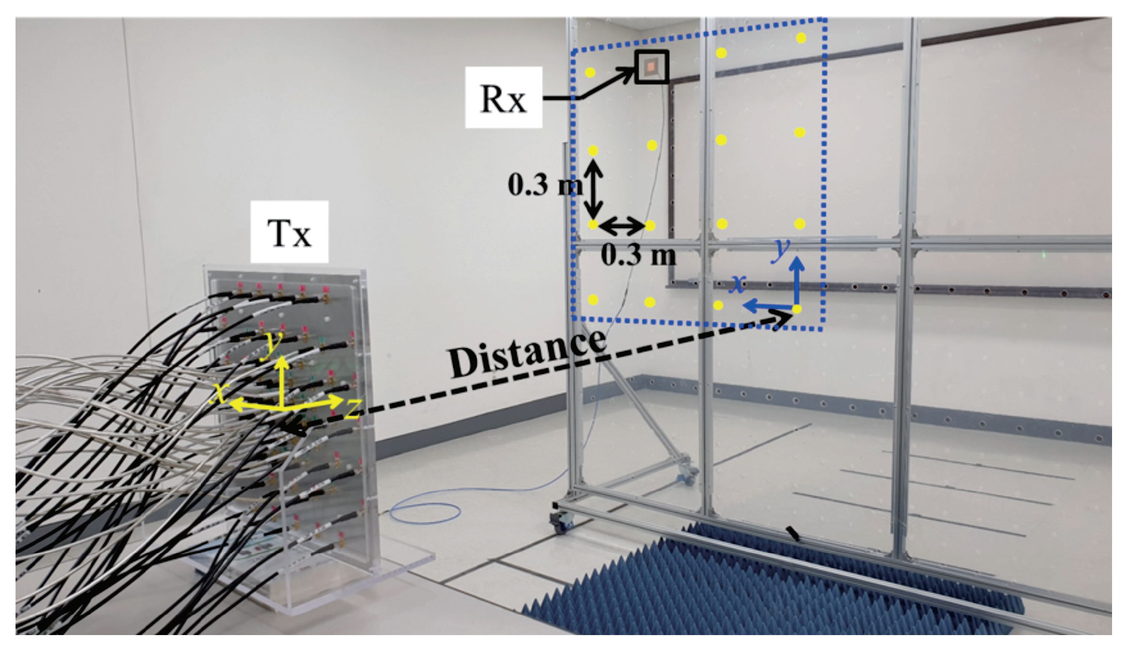
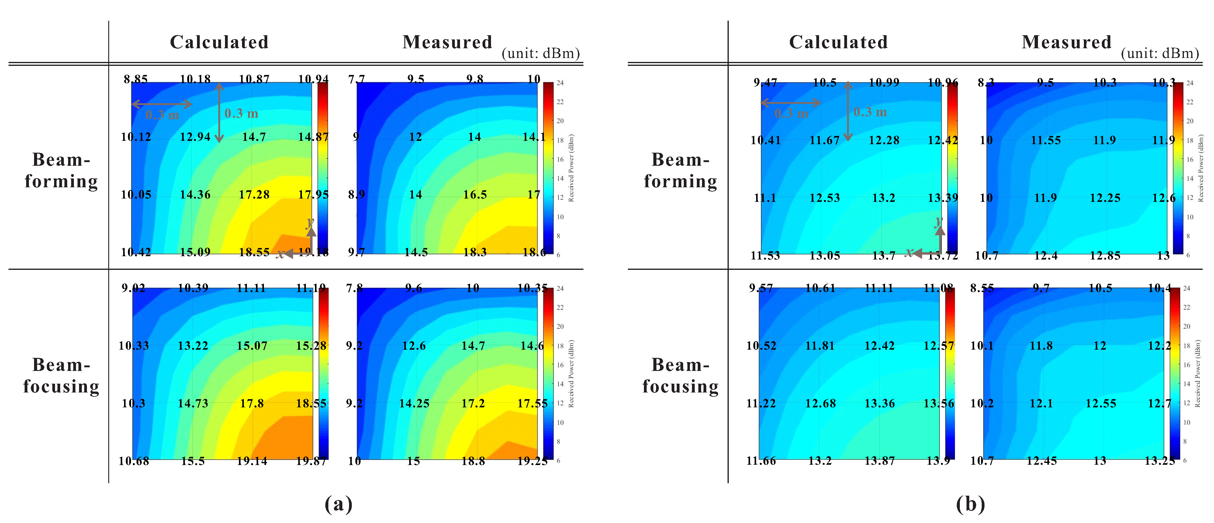
3.1.2. WPT Experiment (2): Varying the Rx Position and the Direction of Beam-Forming
3.2. Dual-Band (2.4 and 5.8 GHz) RF WPT Experiment
3.2.1. WPT Experiment (3): With a Dual-Band Rx Antenna
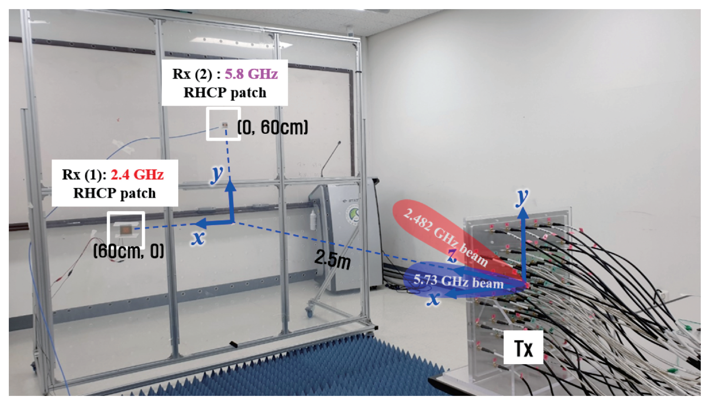
3.2.2. WPT Experiment (4): With Two Rx Antennas Operating at Two Different Frequencies
4. Conclusions
Author Contributions
Funding
Institutional Review Board Statement
Informed Consent Statement
Data Availability Statement
Conflicts of Interest
References
- Ciccia, S.; Scionti, A.; Franco, G.; Giordanengo, G.; Terzo, O.; Vecchi, G. A Multi-Tone Rectenna System for Wireless Power Transfer. Energies 2020, 13, 2374. [Google Scholar] [CrossRef]
- Choi, K.W.; Ginting, L.; Aziz, A.A.; Setiawan, D.; Park, J.H.; Hwang, S.I.; Kang, D.S.; Chung, M.Y.; Kim, D.I. Toward Realization of Long-Range Wireless-Powered Sensor Networks. IEEE Wireless Commun. 2019, 26, 184–192. [Google Scholar] [CrossRef]
- Tran, N.M.; Amri, M.M.; Park, J.H.; Hwang, S.I.; Kim, D.I.; Choi, K.W. A Novel Coding Metasurface for Wireless Power Transfer Applications. Energies 2019, 12, 4488. [Google Scholar] [CrossRef] [Green Version]
- Kim, Y.; Boo, S.; Kim, G.; Kim, N.; Lee, B. Wireless Power Transfer Efficiency Formula Applicable in Near and Far Fields. J. Electromagn. Eng. Sci. 2019, 19, 239–244. [Google Scholar] [CrossRef]
- Malik, B.T.; Doychinov, V.; Hayajneh, A.M.; Zaidi, S.A.R.; Robertson, I.D.; Somjit, N. Wireless Power Transfer System for Battery-Less Sensor Nodes. IEEE Access 2020, 8, 95878–95887. [Google Scholar] [CrossRef]
- Xie, L.; Shi, Y.; Hou, Y.T.; Lou, A. Wireless Power Transfer and Applications to Sensor Networks. IEEE Wirel. Commun. 2013, 20, 140–145. [Google Scholar]
- Yi, X.; Chen, X.; Zhou, L.; Hao, S.; Zhang, B.; Duan, X. A Microwave Power Transmission Experiment Based on the Near-Field Focused Transmitter. IEEE Antennas Wirel. Propag. Lett. 2019, 18, 1105–1108. [Google Scholar] [CrossRef]
- Khang, S.-T.; Lee, D.-J.; Hwang, I.-J.; Yeo, T.-D.; Yu, J.-W. Microwave Power Transfer With Optimal Number of Rectenna Arrays for Midrange Applications. IEEE Antennas Wirel. Propag. Lett. 2018, 17, 155–159. [Google Scholar] [CrossRef]
- Kang, E.; Hur, J.; Seo, C.; Lee, H.; Choo, H. High Aperture Efficiency Array Antenna for Wireless Power Transfer Applications. Energies 2020, 13, 2241. [Google Scholar] [CrossRef]
- Naji, D.K. Miniature Slotted Semi-Circular Dual-Band Antenna for WiMAX and WLAN Applications. J. Electromagn. Eng. Sci. 2020, 20, 115–124. [Google Scholar] [CrossRef]
- Sasikala, T.; Arunchandar, R.; Bhagyaveni, M.A.; Shanmuga Priya, M. Design of Dual-Band Antenna for 2.45 and 5.8 GHz ISM Band. Nation Acad. Sci. Lett. 2019, 42, 221–226. [Google Scholar] [CrossRef]
- Fereshtian, A.; Ghalibafan, J. Impedance Matching and Efficiency Improvement of a Dual-Band Wireless Power Transfer System Using Variable Inductance and Coupling Method. AEUE Trans. Int. J. Electron. Commun. 2020, 116, 116. [Google Scholar] [CrossRef]
- Kung, M.-L.; Lin, K.-H. Dual-Band Coil Module With Repeaters for Diverse Wireless Power Transfer Applications. IEEE Trans. Microw. Theory Techn. 2018, 66, 332–345. [Google Scholar] [CrossRef]
- Liu, M.; Chen, M. Dual-Band Wireless Power Transfer With Reactance Steering Network and Reconfigurable Receivers. IEEE Trans. Power Electron. 2020, 35, 496–507. [Google Scholar] [CrossRef]
- Ahn, D.; Mercier, P.P. Wireless Power Transfer With Concurrent 200-kHz and 6.78-MHz Operation in a Single-Transmitter Device. IEEE Trans. Power Electron. 2016, 31, 5018–5029. [Google Scholar] [CrossRef]
- Haerinia, M.; Noghanian, S. A Printed Wearable Dual-Band Antenna for Wireless Power Transfer. Sensors 2019, 19, 1732. [Google Scholar] [CrossRef] [PubMed] [Green Version]
- Shrestha, S.; Lee, S.R.; Choi, D.Y. A New Fractal-Based Miniaturized Dual Band Patch Antenna for RF Energy Harvesting. Int. J. Antennas Propag. 2014, 2014, 1–9. [Google Scholar] [CrossRef]
- Niotaki, K.; Cañavate-Sánchez, M.J.; Collado, A.; Goussetis, G.; Georgiadis, A.; Brazil, T. 2.45/5.8 GHz Dual-Band Power Amplifier for Wireless Power Transfer in Space Applications. In Proceedings of the Active and Passive RF Devices, London, UK, 8 May 2017; pp. 1–4. [Google Scholar]
- Bergès, R.; Fadel, L.; Oyhenart, L.; Vigneras, V.; Taris, T. A Dual Band 915MHz/2.44GHz RF Energy Harvester. In Proceedings of the 2015 European Microwave Conference (EuMC), Paris, France, 7–10 September 2015; pp. 307–310. [Google Scholar]
- Wang, H.; Deng, L.; Luo, H.; Du, J.; Zhou, D.; Huang, S. Microwave Wireless Power Transfer System Based on a Frequency Reconfigurable Microstrip Patch Antenna Array. Energies 2021, 14, 415. [Google Scholar] [CrossRef]
- Miller, T.; Oyewobi, S.S.; Abu-Mahfouz, A.M.; Hancke, G.P. Enabling a Battery-Less Sensor Node Using Dedicated Radio Frequency Energy Harvesting for Complete Off-Grid Applications. Energies 2020, 13, 5402. [Google Scholar] [CrossRef]
- Trinh-Van, S.; Lee, J.M.; Yang, Y.; Lee, K.-Y.; Hwang, K.C. Improvement of RF Wireless Power Transmission Using a Circularly Polarized Retrodirective Antenna Array With EBG Structures. Appl. Sci. 2018, 8, 324. [Google Scholar] [CrossRef] [Green Version]
- Fairouz, M.; Saed, M.A. A Complete System of Wireless Power Transfer Using a Circularly Polarized Retrodirective Array. J. Electromagn. Eng. Sci. 2020, 20, 139–144. [Google Scholar] [CrossRef]
- Kwon, G.; Park, J.Y.; Kim, D.H.; Hwang, K.C. Optimization of a Shared-Aperture Dual-Band Transmitting/Receiving Array Antenna for Radar Applications. IEEE Trans. Antennas Propag. 2017, 65, 7038–7051. [Google Scholar] [CrossRef]
- Gal, R.; Shavit, R. Thinning Satellite Communication Antenna Arrays for Dual Band Operation. In Proceedings of the IEEE International Conference on the Science of Electrical Engineering (ICSEE), Eilat, Israel, 12–14 December 2018; pp. 1–5. [Google Scholar]
- Liu, C.; Wu, H.-N. Synthesis of Thinned Array With Side Lobe Levels Reduction Using Improved Binary Invasive Weed Optimization. Prog. Electromagn. Res. M 2014, 37, 21–30. [Google Scholar] [CrossRef] [Green Version]
- Brahma, P.; Nandi, P.; Senapati, A.; Roy, J.S. Reduction of Side-Lobe Level of Thinned Phased Array Antenna Using Genetic Algorithm. Int. J. Comput. Appl. 2015, 112, 13–15. [Google Scholar]
- Gangwar, V.S.; Samminga, R.K.; Singh, A.K.; Jijenth, M.; Suman, K.K.; Singh, S.P. A Novel Strategy for the Synthesis of Thinned Planar Antenna Array Which Furnishes Lowest Possible Peak Side Lobe Level Without Appearance of Grating Lobes Over Wide Steering Angles. J. Electromagn. Waves Appl. 2018, 32, 842–857. [Google Scholar] [CrossRef]
- Razavi, A.; Forooraghi, K. Thinned Arrays Using Pattern Search Algorithms. Prog. Electromagn. Res. 2008, 78, 61–71. [Google Scholar] [CrossRef] [Green Version]
- Jain, R.; Mani, G.S. Solving “Antenna Array Thinning Problem” Using Genetic Algorithm. Appl. Comput. Intell. Soft Comput. 2012, 24, 946398. [Google Scholar] [CrossRef] [Green Version]
- Balanis, C.A. Antenna Theory: Analysis and Design, 3rd ed.; John Wiley & Sons: Hoboken, NJ, USA, 2005. [Google Scholar]
- Buffi, A.; Nepa, P.; Manara, G. Design Criteria for Near-Field-Focused Planar Arrays. IEEE Antennas Propag. Mag. 2012, 54, 40–50. [Google Scholar] [CrossRef]
- Bae, J.; Yi, S.; Koo, H.; Oh, S.; Oh, H.; Choi, W.; Shin, J.; Song, C.M.; Hwang, K.; Lee, K.; et al. LUT-Based Focal Beamforming System Using 2-D Adaptive Sequential Searching Algorithm for Microwave Power Transfer. IEEE Access 2020, 8, 196024–196033. [Google Scholar] [CrossRef]
- Li, P.F.; Qu, S.W.; Yang, S.; Nie, Z.P. Microstrip Array Antenna With 2-D Steerable Focus in Near-Field Region. IEEE Trans. Antennas Propag. 2017, 65, 4607–4617. [Google Scholar] [CrossRef]
- Song, C.M.; Trinh-Van, S.; Lee, S.-H.; Bae, J.; Yang, Y.; Lee, K.-Y.; Hwang, K.C. Analysis of Received Power in RF Wireless Power Transfer System With Array Antennas. IEEE Access 2021, 9, 76315–76324. [Google Scholar] [CrossRef]
- Geary, K.; Schaffner, J.H.; Hsu, H.-P.; Song, H.J.; Colburn, J.S.; Yasan, E. Single-Feed Dual-Band Stacked Patch Antenna for Orthogonal Circularly Polarized GPS and SDARS Applications. In Proceedings of the 2008 IEEE 68th Vehicular Technology Conference, Calgary, AB, Canada, 24 October 2008; pp. 1–5. [Google Scholar]
- Wang, X.; Sha, S.; He, J.; Guo, L.; Lu, M. Wireless Power Delivery to Low-Power Mobile Devices Based on Retro-Reflective Beamforming. IEEE Antennas Propag. Mag. 2014, 13, 919–922. [Google Scholar] [CrossRef]
- Gowda, V.R.; Yurduseven, O.; Lipworth, G.; Zupan, T.; Reynolds, M.S.; Smith, D.R. Wireless Power Transfer in the Radiative Near Field. IEEE Antennas Wirel. Propag. Lett. 2016, 15, 1865–1868. [Google Scholar] [CrossRef]


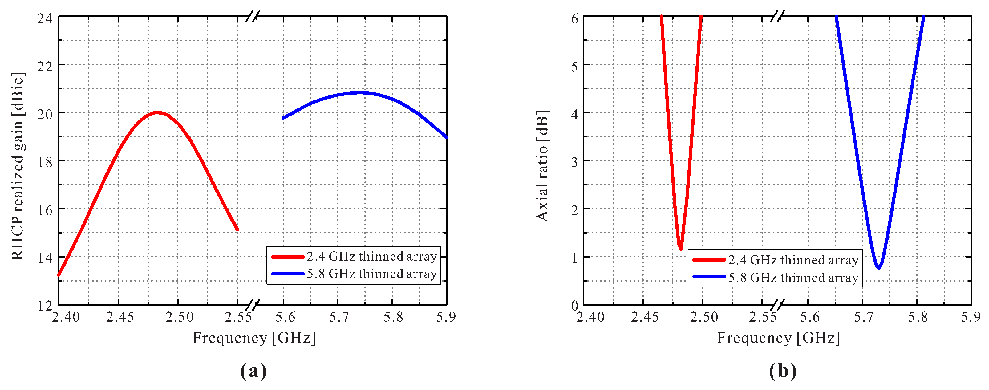
| 2.4 GHz Array (Figure 8a) | 5.8 GHz Array (Figure 8b) | Proposed Dual-Band Array (Figure 5) | ||
|---|---|---|---|---|
| Operating frequency | 2.482 GHz | 5.73 GHz | 2.482 GHz | 5.73 GHz |
| Radiating elements | 32 | 32 | 32 | 32 |
| Realized gain | 20 dBic | 20.8 dBic | 20 dBic | 20.8 dBic |
| Aperture area | 39 × 39 cm2 | 18.3 × 18.3 cm2 | 43.7 × 43.7 cm2 | |
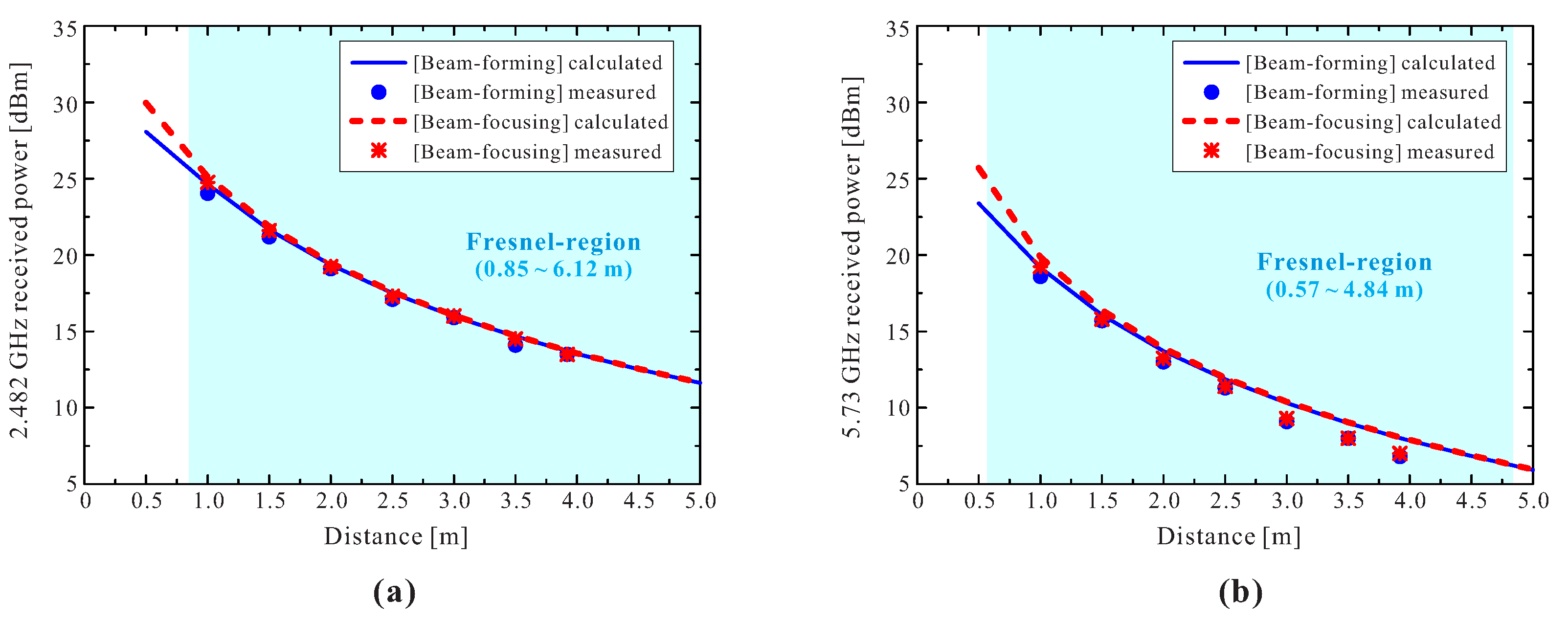
| Distance | Beam-Forming (In-Phase) | Beam-Focusing | ||
|---|---|---|---|---|
| Calculated | Measured | Calculated | Measured | |
| 1 m | 24.63 dBm (0.2904 W) | 24.05 dBm (0.2541 W) | 25.13 dBm (0.3258 W) | 24.75 dBm (0.2985 W) |
| 1.5 m | 21.65 dBm (0.1462 W) | 21.20 dBm (0.1318 W) | 21.87 dBm (0.1538 W) | 21.60 dBm (0.1445 W) |
| 2 m | 19.36 dBm (0.0863 W) | 19.10 dBm (0.0813 W) | 19.49 dBm (0.0889 W) | 19.25 dBm (0.0841 W) |
| 2.5 m | 17.51 dBm (0.0564 W) | 17.10 dBm (0.0513 W) | 17.59 dBm (0.0574 W) | 17.30 dBm (0.0537 W) |
| 3 m | 15.98 dBm (0.0396 W) | 15.90 dBm (0.0389 W) | 16.04 dBm (0.0402 W) | 16.00 dBm (0.0398 W) |
| 3.5 m | 14.67 dBm (0.0293 W) | 14.10 dBm (0.0257 W) | 14.72 dBm (0.0296 W) | 14.50 dBm (0.0282 W) |
| 3.92 m | 13.71 dBm (0.0235 W) | 13.50 dBm (0.0224 W) | 13.74 dBm (0.0237 W) | 13.50 dBm (0.0224 W) |
| Distance | Beam-Forming (In-Phase) | Beam-Focusing | ||
|---|---|---|---|---|
| Calculated | Measured | Calculated | Measured | |
| 1 m | 19.18 dBm (0.0828 W) | 18.60 dBm (0.0724 W) | 19.87 dBm (0.0971 W) | 19.25 dBm (0.0841 W) |
| 1.5 m | 16.07 dBm (0.0405 W) | 15.70 dBm (0.0372 W) | 16.39 dBm (0.0436 W) | 15.80 dBm (0.0380 W) |
| 2 m | 13.72 dBm (0.0236 W) | 13.00 dBm (0.0200 W) | 13.90 dBm (0.0245 W) | 13.25 dBm (0.0211 W) |
| 2.5 m | 11.85 dBm (0.0153 W) | 11.30 dBm (0.0135 W) | 11.97 dBm (0.0157 W) | 11.40 dBm (0.0138 W) |
| 3 m | 10.31 dBm (0.0107 W) | 9.10 dBm (0.0081 W) | 10.39 dBm (0.0109 W) | 9.30 dBm (0.0085 W) |
| 3.5 m | 8.99 dBm (0.0079 W) | 8.00 dBm (0.0063 W) | 9.05 dBm (0.0080 W) | 8.00 dBm (0.0063 W) |
| 3.92 m | 8.02 dBm (0.0063 W) | 6.80 dBm (0.0048 W) | 8.07 dBm (0.0064 W) | 7.00 dBm (0.0050 W) |
| Received Power | Rx: Dual-Band Antenna | |||
|---|---|---|---|---|
| 2.482 GHz | 5.73 GHz | |||
| Calculated | Measured | Calculated | Measured | |
| Beam-forming (in-phase) | 23.13 dBm | 22.3 dBm | 12.92 dBm | 12.6 dBm |
| Beam-focusing | 23.55 dBm | 22.45 dBm | 13.46 dBm | 13.15 dBm |
| Beam-Focusing | Rx(1): 2.4 GHz Patch | Rx(2): 5.8 GHz Patch | ||
|---|---|---|---|---|
| 2.482 GHz | 5.73 GHz | |||
| Calculated | Measured | Calculated | Measured | |
| Received power | 16.57 dBm | 15.57 dBm | 11.47 dBm | 10.58 dBm |
| (WPT efficiency) | (0.454%) | (0.361%) | (0.140%) | (0.114%) |
| Frequency | Polarization | Size of Tx Antenna | Distance | Size of Rx Antenna | (WPT Efficiency) | ||
|---|---|---|---|---|---|---|---|
| [7] | 5.8 GHz | LP (linear polarization) | 1 × 1 m2 | 500 W | 10 m | 1 × 1 m2 | 209.26 W (41.85%) |
| [8] | 2.45 GHz | LP | 1 × 0.122 m2 | 0.25 W | 1 m | 0.5 × 0.122 m | 0.0125 W (5.01%) |
| [37] | 2.08 GHz | LP | 0.28 × 0.1 m2 (guess) | 1 W | 0.5 m | 0.07 × 0.1 m2 (guess) | 0.014 W (1.4%) |
| [38] | 5.8 GHz | LP | 0.217 × 0.217 m2 | 0.1 W | 0.4 m | 0.16 × 0.16 m2 | 0.0332 W (0.332%) |
| This study | 2.482 GHz | CP (circular polarization) | 0.44 × 0.44 m2 | 10 W | 1–3.92 m | 0.063 × 0.063 m2 | 0.2985 W–0.0224 W (2.985–0.224%) |
| 5.73 GHz | 10 W | 0.031 × 0.031 m2 | 0.0841 W–0.005 W (0.841–0.05%) |
Publisher’s Note: MDPI stays neutral with regard to jurisdictional claims in published maps and institutional affiliations. |
© 2021 by the authors. Licensee MDPI, Basel, Switzerland. This article is an open access article distributed under the terms and conditions of the Creative Commons Attribution (CC BY) license (https://creativecommons.org/licenses/by/4.0/).
Share and Cite
Song, C.-M.; Lim, H.-J.; Trinh-Van, S.; Lee, K.-Y.; Yang, Y.; Hwang, K.-C. Dual-Band RF Wireless Power Transfer System with a Shared-Aperture Dual-Band Tx Array Antenna. Energies 2021, 14, 3803. https://doi.org/10.3390/en14133803
Song C-M, Lim H-J, Trinh-Van S, Lee K-Y, Yang Y, Hwang K-C. Dual-Band RF Wireless Power Transfer System with a Shared-Aperture Dual-Band Tx Array Antenna. Energies. 2021; 14(13):3803. https://doi.org/10.3390/en14133803
Chicago/Turabian StyleSong, Chan-Mi, Hong-Jun Lim, Son Trinh-Van, Kang-Yoon Lee, Youngoo Yang, and Keum-Cheol Hwang. 2021. "Dual-Band RF Wireless Power Transfer System with a Shared-Aperture Dual-Band Tx Array Antenna" Energies 14, no. 13: 3803. https://doi.org/10.3390/en14133803
APA StyleSong, C.-M., Lim, H.-J., Trinh-Van, S., Lee, K.-Y., Yang, Y., & Hwang, K.-C. (2021). Dual-Band RF Wireless Power Transfer System with a Shared-Aperture Dual-Band Tx Array Antenna. Energies, 14(13), 3803. https://doi.org/10.3390/en14133803