Article

The Interconnection and Damping Assignment Passivity-Based Control Synthesis via the Optimal Control Method for Electric Vehicle Subsystems

1
Institute of Power Engineering and Control Systems, Lviv Polytechnic National University, 12 Bandera Street, 79013 Lviv, Ukraine
2
Faculty of Transport, Electrical Engineering and Computer Science, University of Technology and Humanities in Radom, 29 Malczewskiego Street, 26-600 Radom, Poland
*
Author to whom correspondence should be addressed.
Energies 2021, 14(12), 3711; https://doi.org/10.3390/en14123711
Submission received: 5 May 2021 / Revised: 27 May 2021 / Accepted: 16 June 2021 / Published: 21 June 2021
(This article belongs to the Special Issue Power Processing Systems for Electric Vehicles)

Abstract

:
The interconnection between optimal control theory and the theory of energy-shaping control is described in our paper. For linear and nonlinear systems, the application of the theory of optimal control for the synthesis of parameters of energy-shaping control matrices is demonstrated in detail. The use of a Riccati equation allows us to form an optimality criterion and to synthesize the energy-shaping control system that provides the desired transient processes. The proposed approach was applied to the synthesis of control influences for electric vehicle subsystems, such as a two-mass system and a permanent magnets synchronous motor. The results of computer simulation studies, as well as those conducted on real experimental installations, are given in this paper.

1. Introduction

In recent decades, there has been a significant gap between the development of the theory of automatic control and the practical application of the established methods of the synthesis of control influences in technical systems. Modern systems, including electromechanical ones, are complex nonlinear objects. The use of nonlinear control theory [1,2,3] methods in such systems (especially feedback linearization, backstepping, and passivity-based control, as shown in [4,5,6]) creates new opportunities to synthesize effective control algorithms and to improve the dynamic and static characteristics of the systems themselves. At the same time, the mentioned methods of control systems synthesis are quite complex from a mathematical point of view, requiring specialist knowledge for their understanding and application; thus, their widespread use has declined for the time being. A common feature of the above-mentioned methods is the formation of control influences based on state variables [1,7], which will ensure the stability of the synthesized system. In the first case, the control coefficients based on the full state vector are in the new coordinate basis where the system is linear, and then there is a transition to the main coordinate basis. In the other two, the control synthesis is based on the iterative process [8,9]. In the backstepping method, synthesis occurs by increasing the complexity of the system and using a special type of Lyapunov function. In the passivity-based control method, synthesis is performed by splitting the trajectory into individual sections and finding optimal control over this time interval based on the application of the Fréchet derivative [10]. Unlike the methods of feedback linearization and backstepping, the method of passivity-based control, as a representative of energy-based approaches, is based on the physical laws of energy transfer and conversion [11]. This makes its application promising in electromechanical systems, particularly in electric vehicles [12,13], where the energy flow control system is at the core. As noted in [14] the main difficulties in the application of energy-shaping control are both the structure selection of the matrices of interconnections between subsystems and damping and the synthesis of the parameters of these matrices. For a linear system, as described in [15], the relationship between the theory of optimal control and interconnection and damping assignment passivity-based control (IDA-PBC) is shown, and the problems that need to be solved are formulated. In [11], for the synthesis of the control influence, the Ricatti equation for a single point in the state space was applied to form the control as a combination of the control influences obtained at individual points. The formulation of the problem of energy-shaping control synthesis, based on the theory of optimal control for a linear system, is caused primarily by the fact that the nonlinear theory of optimal control for the synthesis of control influence requires solving the Hamilton–Jacobi–Bellman equation [16], which is also difficult in complex systems. The linear theory of optimal control makes it possible to obtain a solution to the problem in the form of a matrix of feedback on state variables. These variables correspond to the principles of energy-shaping control. At the same time, the application of fuzzy set theory makes it possible to consider certain classes of nonlinear systems, including electromechanical systems, as a family of dynamic linear systems, and to synthesize a fuzzy controller based on the methods of classical control theory [17]. Thus, the synthesis of IDA-PBC via the linear theory of optimal control and its extension to nonlinear systems is an important task, especially for electric vehicles.
Due to the permanent development of electric vehicles in recent years [18], electric vehicles can be chosen as an example onto which we can apply the proposed ideas. In a modern electric car, the most crucial factor is an effective use of the battery charge [19,20,21], which is an energy management challenge that can be correctly formulated and solved with energy-based approaches. An electric vehicle is a complex electromechanical system which consists of different types of subsystems, and each of them is important, particularly the wheels, shaft, electric motor, inverter, traction battery, internal combustion engine, generator, etc. [22]. The mechanical parts of the whole powertrain (whether they be wheels, hubs, motors, or shafts), can be considered constitutive of a two-mass subsystem [23]. Despite the use of different types of motors in electrical vehicles (Direct Current Motor, Brushless Direct Current Motor, Alternating Current Motor, and Switched Reluctance Motor) [24], the most popular is a Permanent Magnet Synchronous Motor (PMSM). This is because of its high power rating and efficiency. The PMSM is a nonlinear system that requires a more complex control system design [25].
Considering the feasibility of passivity-based control in electromechanical systems, where providing optimal energy efficiency and energy flow management are key issues, this article aims to solve the problem of synthesis for control system interconnection and damping matrices with the use of the classical theory of optimal control.

2. Synthesis of Energy-Shaping Control in the Case of a Linear System

A linear system in well-known state-space representation is the following:
d x d t = A x + B u ,
and, when moving to a desired state, it transforms to:
A x z + B u z = 0 ,
where xz—desired state vector and uz—desired input vector.
In this case, for the integral quality criterion, we obtain the following expression:
= 0 t 1 [ ( x x z ) T R 1 ( x x z ) + ( u u z ) T R 2 ( u u z ) λ ( t ) ( A x + B u x ˙ A x z B u z ) ] d t ,
where R 1 and R 2 are positive definite matrixes and λ ( t ) —indefinite Lagrange multiplier.
Taking that x * = x x z and u * = u u z , and also given that d x z ( t ) d t = 0 , the formed criterion (2) can be written as follows:
= 0 t 1 [ x * T R 1 x * + u * T R 2 u * λ ( t ) ( A x * + B u * x ˙ * ) ] d t .
When t1 → ∞, an optimal control of the object can be formulated in the form of a linear law u * = K x * , where the matrix of feedback coefficients K is determined by the formula K = R 2 ( 1 ) B T P , where P is the only non-negative symmetric solution of the algebraic Riccati equation:
A T P + P A + R 1 P B R 2 1 B T P = 0
Then, the optimal control, which transits the system from any arbitrary state to a desired state, is determined as follows:
u = u z K x + K x z .
In the case of energy-shaping control (in particular IDA-PBC), when considering the system as port-controlled Hamiltonian (PCH), the model of the linear system will look like:
{ x 1 ˙ = [ J R ] H x 1 + G u y = G T H x 1 ,
where J = J T —skew-symmetric matrix that reflects the interconnections in the controlled object; R = R T 0 —symmetric positive matrix that reflects the loss (damping) in the controlled object; H = 1 / 2 x 1 T D 1 x 1 —total energy function (Hamiltonian); x 1 —a state vector in PCH representation, the elements of which are various energy impulses; D—diagonal matrix of inertia coefficients; G—port matrix in PCH representation.
According to the IDA-PBC procedure, the control system synthesis is reduced to determining the structures of the new internal energy interconnections Ja and damping Ra that provide the necessary behavior of the system [26]. The introduction of additional interconnections is carried out in order to change the flow of energy between the subsystems. It will lead to new forces that will move the system to a given point of equilibrium. The introduction of damping is carried out for the purpose of natural redistribution of energy, which leads to the damping of oscillations in the system and ensures its asymptotic stability. The model of the desired asymptotically stable closed-loop Hamiltonian control system is described by the following equation:
x 1 ˙ = [ J d R d ] H d x 1 ,
where J d = J + J a = J d T —matrix that reflects the interconnections in the desired system; R d = R + R a = R d T 0 —matrix that reflects the loss (damping) in the desired system; H d = 1 / 2 x 1 0 T D 1 x 1 0 + 1 / 2 ( x 1 x 1 0 ) T D 1 ( x 1 x 1 0 ) —the energy function of the desired closed-loop control system for the equilibrium point x 1 0 .
Then, the equation for the control influences of the control system of partial derivatives will look like:
G u = [ J d R d ] H d x 1 [ J R ] H x 1
or
G u = [ { J + J a } { R + R a } ] H d x 1 [ J R ] H x 1 .
Given that x1 = D·x and x10 = D·xz, while H x 1 = x and H d x 1 = x x z , we will receive:
D x ˙ = [ J R ] x + G u   or   x ˙ = D 1 [ J R ] x + D 1 G u = A x + B u
and
G u = [ { J + J a } { R + R a } ] ( x x z ) [ J R ] x = [ J a R a ] ( x x z ) [ J R ] x z .
In order to find the control according to the energy-shaping approach, the expression should be multiplied by D 1 :
D 1 G u = D 1 [ J a R a ] ( x x z ) D 1 [ J R ] x z
or
u = G 1 [ J a R a ] ( x x z ) B 1 A x z .
Taking into account that u z = B 1 A x z by analogy with the system of optimal control, the control influence, which transits the system from any arbitrary state to a desired state, can be written as follows:
u = u z K 1 ( x x z )
where K 1 = G 1 [ J a R a ] . It should be noted that the state of the system with optimal control and energy-shaping control is determined by different state vectors: in the first case, the coordinates of the state, and in the second, energy pulses. Given the relationship between the vector of energy pulses and the coordinates of the state, it can be written as K = D 1 K 1 , and then:
K = R 2 1 B T P = D 1 G 1 [ J a R a ] .
Let W = J a R a = G D R 2 1 B T P . Then, taking into account that J a = J a T —skew-symmetric matrix and R a = R a T 0 —symmetric matrix, we will receive:
{ J a = 1 2 ( W W T ) = 1 2 ( G D R 2 1 B T P ( G D R 2 1 B T P ) T ) R a = 1 2 ( W + W T ) = 1 2 ( G D R 2 1 B T P + ( G D R 2 1 B T P ) T ) .
In energy-shaping control, the matrix J a forms energy flows between individual subsystems. If we were to take for a linear system that J a = 0 , then the damping matrix is defined as follows:
R a = G D R 2 1 B T P = G D R 2 1 ( D 1 G ) T P .
Thus, IDA-PBC provides the formation of optimal control influences. In the case of the control object being a linear system, it could be synthesized using the theory of optimal control.

3. Study of the Efficiency of Synthesized Control in a Two-Mass System

Consider the application of the proposed approach to the synthesis of a control system for a two-mass subsystem for the electrical vehicle. The traditional model of a two-mass system looks like this [6]:
{ J 1 d ω 1 d t = M M c 1 b 1 ω 1 c Δ ϕ β ( ω 1 ω 2 ) J 2 d ω 2 d t = c Δ ϕ + β ( ω 1 ω 2 ) M c 2 b 2 ω 2 c d Δ ϕ d t = c ( ω 1 ω 2 )
where J1 and J2—moments of inertia of the motor’s rotor and the mechanism, respectively; ω1 and ω2—angular velocities of the engine and mechanism, respectively; M—torque of the drive mechanism (electromagnetic moment of the motor); Mc1 and Mc2—static moments acting on the motor itself and the mechanism, respectively; b1 and b2—coefficients of external viscous friction of the motor and mechanism; c—transmission stiffness factor; Δϕ—twist angle; β—coefficient of internal viscous friction.
There is a more accurate representation of the last equation in (9) using the Caputo–Fabrizio operator, where elastic moment is formed in the following way:
M 12 = c Δ φ = c ( ω 1 ω 2 ) d t ,
then s M 12 = c α ( ω 1 ω 2 ) 1 α α M 12 .
From another hand, our system is not a positional system which, according to [27], allows us to use the traditional representation of a two-mass system (9). As follows, in vector-matrix form (1), the model of a two-mass system (9) will take the form:
d d t [ ω 1 ω 2 Δ φ ] = [ b 1 β J 1 β J 1 c J 1 β J 2 b 2 β J 2 c J 2 1 1 0 ] [ ω 1 ω 2 Δ φ ] + [ 1 J 1 1 J 1 0 0 0 1 J 2 0 0 0 ] [ M M c 1 M c 2 ] .
When writing a controlled object as a PCH (5), the system model will look like:
{ d x 1 d t = d d t [ J 1 ω 1 J 2 ω 2 c Δ φ ] = D d d t [ ω 1 ω 2 Δ φ ] = { [ 0 0 c 0 0 c c c 0 ] [ b 1 + β β 0 β b 2 + β 0 0 0 0 ] } H x 1 + [ 1 0 0 0 1 0 0 0 1 ] [ M M c 1 M c 2 0 ] y = [ 1 0 0 0 1 0 0 0 1 ] H x 1
where D = d i a g [ J 1 J 2 c ] .
The Hamiltonian of the system will be as follows:
H ( x 1 ) = 1 2 x 1 T D 1 x 1 = 1 2 ( 1 J 1 x 1 1 2 + 1 J 2 x 1 2 2 + 1 c x 1 3 2 ) .
Then given H x 1 = [ ω 1 ω 2 Δ φ ] T :
D d d t [ ω 1 ω 2 Δ φ ] = { [ 0 0 c 0 0 c c c 0 ] [ b 1 + β β 0 β b 2 + β 0 0 0 0 ] } [ ω 1 ω 2 Δ φ ] + [ 1 0 0 0 1 0 0 0 1 ] [ M M c 1 M c 2 0 ]
and accordingly, based on (6), the following matrices can be found:
A = [ J 1 0 0 0 J 2 0 0 0 c ] 1 { [ 0 0 c 0 0 c c c 0 ] [ b 1 + β β 0 β b 2 + β 0 0 0 0 ] } = [ b 1 β J 1 β J 1 c J 1 β J 2 b 2 β J 2 c J 2 1 1 0 ] , B = [ J 1 0 0 0 J 2 0 0 0 c ] 1 [ 1 0 0 0 1 0 0 0 1 ] = [ 1 J 1 0 0 0 1 J 2 0 0 0 1 c ] [ 1 J 1 1 J 1 0 0 0 1 J 2 0 0 0 ] .
Thus, the matrix of control influences B (9), which is obtained from the model in PCH representation, differs from the traditional one obtained from the representation of the system in the state-space form. The presence of fictitious control influence 1 c 0 allows, unlike writing the system in the form of state variables, for the finding of uz as the solution of the system A x z + B u z = 0 . It is also worth noting that, in the energy-based approach, the control influence is formed as the sum of all influences that operate at a given point in the system, taking into account the sign. Given the above, a model of the system (9) in the form of state variables can be written as:
d d t [ ω 1 ω 2 Δ φ ] = [ b 1 β J 1 β J 1 c J 1 β J 2 b 2 β J 2 c J 2 1 1 0 ] [ ω 1 ω 2 Δ φ ] + [ 1 J 1 0 0 0 1 J 2 0 0 0 1 c ] [ M M c 1 M c 2 0 ]
or, separating the control and perturbing influences traditionally used in the synthesis of control systems, this model can be represented as:
d d t [ ω 1 ω 2 Δ φ ] = [ b 1 β J 1 β J 1 c J 1 β J 2 b 2 β J 2 c J 2 1 1 0 ] [ ω 1 ω 2 Δ φ ] + [ 1 J 1 0 0 0 1 J 2 0 0 0 1 c ] [ M 0 0 ] + [ 1 J 1 0 0 0 1 J 2 0 0 0 1 c ] [ M c 1 M c 2 0 ]
or
d d t [ ω 1 ω 2 Δ φ ] = [ b 1 β J 1 β J 1 c J 1 β J 2 b 2 β J 2 c J 2 1 1 0 ] [ ω 1 ω 2 Δ φ ] + [ 1 J 1 0 0 0 0 0 0 0 0 ] [ M ] + [ 1 J 1 0 0 0 1 J 2 0 0 0 1 c ] [ M c 1 M c 2 0 ] .
Given that the system has only one control influence, the quality criterion (3) will take the following form:
= 0 [ ( x x z ) T R 1 ( x x z ) + α ( u u z ) 2 ] d t
Assume that R1—identity matrix. Then, Riccati’s Equation (4) will take the form:
[ b 1 β J 1 β J 2 1 β J 1 b 2 β J 2 1 c J 1 c J 2 0 ] [ p 11 p 12 p 13 p 21 p 22 p 23 p 31 p 32 p 33 ] + [ p 11 p 12 p 13 p 21 p 22 p 23 p 31 p 32 p 33 ] [ b 1 β J 1 β J 1 c J 1 β J 2 b 2 β J 2 c J 2 1 1 0 ] α 1 [ p 11 p 12 p 13 p 21 p 22 p 23 p 31 p 32 p 33 ] [ 1 J 1 0 0 0 0 0 0 0 0 ] [ 1 J 1 0 0 0 0 0 0 0 0 ] [ p 11 p 12 p 13 p 21 p 22 p 23 p 31 p 32 p 33 ] = [ 1 0 0 0 1 0 0 0 1 ] .
The matrix of feedback coefficients, based on (7), will have the form:
K = α 1 [ 1 J 1 0 0 0 0 0 0 0 0 ] [ p 11 p 12 p 13 p 21 p 22 p 23 p 31 p 32 p 33 ] = α 1 [ p 11 J 1 p 12 J 1 p 13 J 1 0 0 0 0 0 0 ] .
Let the investigated two-mass system have the parameters [28]: J1 = 1 kg·m2, J2 = 3 kg·m2, c = 20,000 N·m, b1 = 0.25 N·m·s, b2 = 0.25 N·m·s, and β = 10 N·m·s. Then, based on (11), the matrix P for α = 0.5 will be the following:
P = [ 0.3320866 0.9039824 0.081817 0.9039824 2.804211 0.2455256 0.081817 0.2455256 615.1483 ] ,
and the matrix of synthesized coefficients based on state variables (12) will appear accordingly as:
K = [ 0.6641732 1.807965 0.1636339 0 0 0 0 0 0 ] .
Given that x z = A 1 B u z , the synthesized control influence will be equal:
u = ( I K A 1 B ) u z K x = [ 5.944 u z 0.6642 ω 1 1.808 ω 2 + 0.1636 Δ φ 0 0 ] .
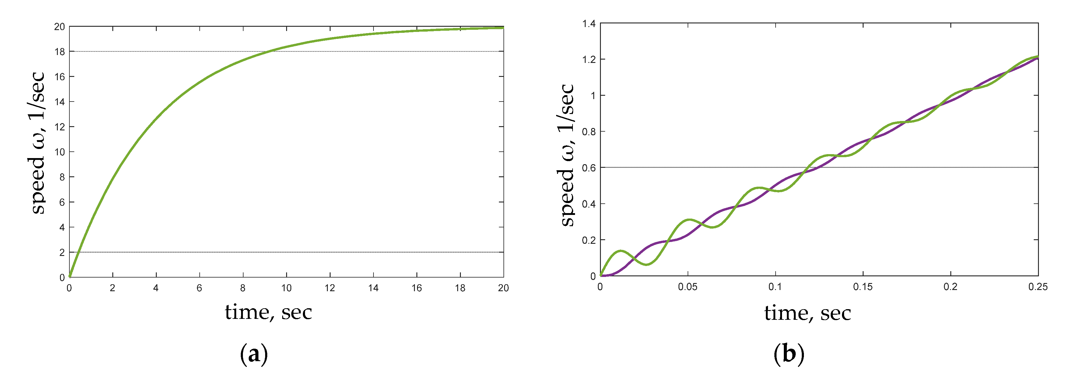
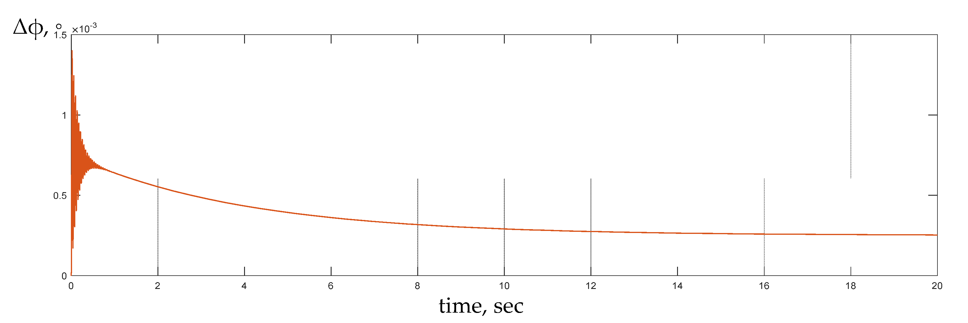
Figure 1 and Figure 2 show the change of system state coordinates for uz = 10 and coefficients, synthesized based on system state variables via optimal control theory.
In the case of energy-shaping control, based on (8), we obtain the following matrices of the control system:
J a = [ 0 0.9039824 0.08181695 0.9039824 0 0 0.08181695 0 0 ] , R a = [ 0.6641732 0.9039824 0.08181695 0.9039824 0 0 0.08181695 0 0 ]
and general control system, synthesized using the general IDA-PBC approach [26] with the selected structure of matrices Ja and Ra, will have the form:
u = [ R a 11 ( ω 01 ω 1 ) + 2 J a 12 ( ω 02 ω 2 ) + 2 J a 13 ( Δ φ 0 Δ φ ) + M c 1 + M c 2 + b 1 ω 01 + b 2 ω 02 0 0 ]
Received energy-shaping control (13) provides the same behavior, as shown in Figure 1 and Figure 2.

4. Synthesis of Optimal Control Based on the Riccati Equation Written in Terms of Energy-Shaping Control

The main problems in the synthesis of optimal control are related to the selection of matrices R1 and R2 and finding the solution to the algebraic Riccati equation—matrix P. In the case of energy-shaping control, the algebraic Riccati equation for finding the matrix P can be represented as follows:
[ D 1 [ J R ] ] T P + P D 1 [ J R ] + R 1 P D 1 G R 2 1 [ D 1 G ] T P = 0
Given the transposition properties of the matrices, the Riccati equation can be written as:
[ J R ] T D 1 P + P D 1 [ J R ] + R 1 P D 1 G R 2 1 G T D 1 P = 0
If taken as a partial case, P = γ D , Riccatti’s equation will take the form:
2 γ R + R 1 γ 2 G R 2 1 G T = 0
and, accordingly:
R 1 = γ 2 G R 2 1 G T + 2 γ R
At the same time:
{ J a = 1 2 ( G D R 2 1 ( D 1 G ) T γ D ( G D R 2 1 ( D 1 G ) T γ D ) T ) = 1 2 γ ( G D R 2 1 G T ( G D R 2 1 G T ) T ) R a = 1 2 ( G D R 2 1 ( D 1 G ) T γ D + ( G D R 2 1 ( D 1 G ) T γ D ) T ) = 1 2 γ ( G D R 2 1 G T + ( G D R 2 1 G T ) T )
and, accordingly:
K = R 2 1 G T γ .
Taking into account the fact that the control signal is supplied to only one port, then:
G U = [ 1 0 0 0 1 0 0 0 1 ] [ u 0 0 ] = [ 1 0 0 0 0 0 0 0 0 ] [ u 0 0 ] .
Let R2—identity matrix, and R1- for the studied two-mass system has the following form:
R 1 = γ 2 G R 2 1 G T + 2 γ R = [ γ 2 + 2 γ ( b 1 + β ) 2 γ β 0 2 γ β γ 2 + 2 γ ( b 1 + β ) 0 0 0 0 ] .
Then, the solution of the algebraic Riccati equation is:
P = [ γ J 1 0 0 0 γ J 2 0 0 0 γ c ] .
In the case of energy-shaping control, the matrix of new internal energy interconnection J2 = 0 and the matrix of formed damping is equal to:
R a = [ γ J 1 0 0 0 0 0 0 0 0 ] .
In this case, energy-shaping control (13) transforms to the form:
u = [ γ J 1 ( ω 01 ω 1 ) + M c 1 + M c 2 + b 1 ω 01 + b 2 ω 02 0 0 ] .
For a traditional system of optimal control, a feedback matrix based on state variables:
K = R 2 1 G T γ = [ γ 0 0 0 0 0 0 0 0 ] .
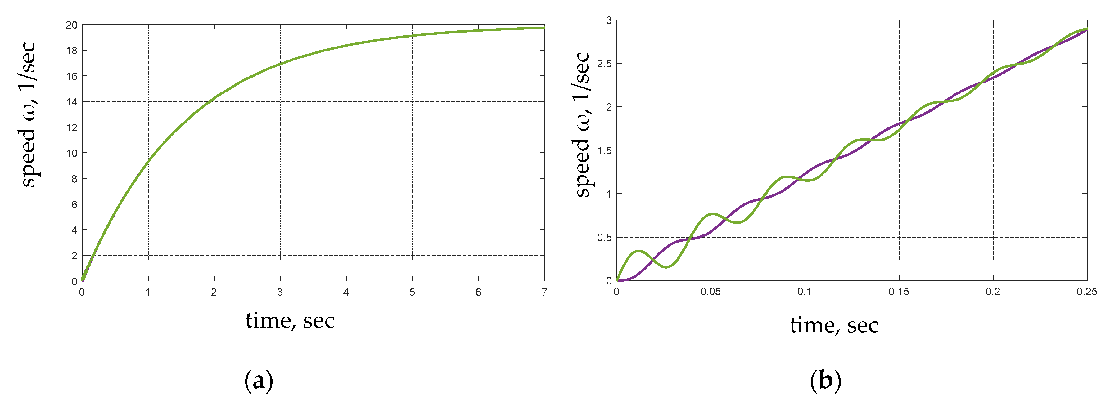
Figure 3, Figure 4, Figure 5 and Figure 6 show the change in the state coordinates of the studied system at uz = 10 and feedback coefficients for the speed of the first mass, synthesized for different values of γ.
The conducted studies confirmed that systems received from both optimal control and IDA-PBC approaches provide the same behavior in the controlled object.

5. Synthesis of Energy-Shaping Control Parameters in the Case of a Nonlinear Electromechanical System

In the case of a nonlinear system, the system model is given in the form:
x ˙ = f ( x ( t ) , u ( t ) , t )   and   x ˙ = f ( x ) + g ( x ) u
The optimal control is based on the solution of the Hamilton–Jacobi–Bellman equation which, under the condition V = V T , has the form:
y x V ( x , t ) t + min u ( V ( x , t ) x f ( x , u ) + 0 t 1 S 1 ( x ( t ) , u ( t ) ) d t )
for the condition V ( x , T ) = S 2 ( x ) , where S 1 and S 2 —formed objective function.
The solution of the Hamilton–Jacobi–Bellman Equation (14) is quite complex due to its nonlinear nature. In the case of a linear system, the Hamilton–Jacobi–Bellman equation is transformed into the well-known Riccati Equation (4).
When using energy-shaping control, the nonlinear system can also be represented in PCH form:
{ x 1 ˙ = [ J ( x 1 ) R ( x 1 ) ] H x 1 + G ( x 1 ) u y = G T ( x 1 ) H x 1
Skew-symmetric matrix J(x1) = −JT(x1) in the case of an electromechanical system can contain both elements that depend on state variables and elements that do not depend on state variables of system x1, and can be written as: J(x1) = J*+ J**(x1). Similarly, a symmetric matrix R(x1) = R*+ R**(x1) can be written. If matrix G does not depend on state variables, the model of the nonlinear system (15) can be written as follows:
{ x 1 ˙ = [ J * R * ] H x 1 + G ( u + G 1 [ J * * ( x 1 ) R * * ( x 1 ) ] H x 1 ) = [ J * R * ] H x 1 + G u * y = G T H x 1
The model of the desired asymptotically stable closed-loop PCH is described by the following equation:
x 1 ˙ = [ J d ( x 1 ) R d ( x 1 ) ] H d x 1
and, taking into account the desired equilibrium point, can be written as:
x 1 ˙ = [ J d * R d * ] H d x 1 .
where J d * = J d ( x 1 0 ) and R d * = R d ( x 1 0 ) —values of the matrices at the point of the state space, which is determined by the state vector of the system x 1 0 .
With forms such as (16) and (17), we come to the synthesis of optimal control for linear systems. Synthesized control influence u* for energy-shaping control, as shown above, is equal to u * = u z K 1 ( x x z ) .
Then
u = u z + G 1 [ J a R a ] ( x x z ) G 1 [ J * * ( x 1 ) R * * ( x 1 ) ] x = u z G 1 [ J a R a ] x z + G 1 [ ( J a J * * ( x 1 ) ) ( R a R * * ( x 1 ) ) ] x .
In the case of control based on the full state vector of the system, we obtain:
u = ( D 1 K ( D 1 [ J * R * ] ) 1 D 1 G ) u z + D 1 G 1 [ J a R a ] x G 1 [ J * * ( x 1 ) R * * ( x 1 ) ] x = ( D 1 K ( D 1 [ J * R * ] ) 1 D 1 G ) u z ( K K * ( x 1 ) ) x
where K * ( x 1 ) = G 1 [ J * * ( x 1 ) R * * ( x 1 ) ] —control influence, which compensates nonlinearities in the electromechanical system.

6. Studies of the Efficiency of the Proposed Approach in the Example of a Permanent Magnet Synchronous Motor Control System

Consider the application of the proposed approach on the example of PMSM control. The model of PMSM in an orthogonal rotating coordinate system d-q, where the d axis is oriented along the rotor flow vector, has the form [14]:
{ L d d i d d t = u d R s i d + p p ω L q i q L q d i q d t = u q R s i q p p ω L d i d p p ω Φ J m d ω d t = 3 2 p p ( ( L d L q ) i d i q + Φ i q ) M L b ω
where Ld and Lq—the inductances of the armature winding (stator) at the axes d and q, respectively; Rs—active resistance of the armature phase winding; pp—number of pole pairs; ω—angular speed of the rotor; Φ—the amplitude of the flux linkage of the armature winding with a pair of poles of the rotor permanent magnets; Im—total moment of inertia; b—coefficients of external viscous friction; ML—moment of static load.
In energy-shaping control, the state vector is x 1 = [ L d i d L q i q 2 3 J m ω ] T , and taking into account the next equations
J ( x 1 ) = J * + J * * ( x 1 ) = [ 0 0 0 0 0 p p Φ 0 p p Φ 0 ] + [ 0 0 p p L q i q 0 0 p p L d i d p p L q i q p p L d i d 0 ] ,
R ( x 1 ) = R * + R * * ( x 1 ) = [ R s 0 0 0 R s 0 0 0 2 3 b ] + [ 0 0 0 0 0 0 0 0 0 ]   and   G = [ 1 0 0 0 1 0 0 0 1 ] ,
the system model will look like:
[ L d 0 0 0 L q 0 0 0 2 3 J m ] d d t [ i d i q ω ] = ( [ 0 0 0 0 0 p p Φ 0 p p Φ 0 ] [ R s 0 0 0 R s 0 0 0 2 3 b ] ) d H ( x 1 ) d x 1 + [ L d 0 0 0 L q 0 0 0 2 3 J m ] d d t [ i d i q ω ] = ( [ 0 0 0 0 0 p p Φ 0 p p Φ 0 ] [ R s 0 0 0 R s 0 0 0 2 3 b ] ) d H ( x 1 ) d x 1 +
+ [ 1 0 0 0 1 0 0 0 1 ] ( [ u d u q M L ] + [ 1 0 0 0 1 0 0 0 1 ] 1 [ 0 0 p p L q i q 0 0 p p L d i d p p L q i q p p L d i d 0 ] d H ( x 1 ) d x 1 )
where H ( x 1 ) = 1 2 [ L d i d L q i q 2 3 J m ω ] [ L d 0 0 0 L q 0 0 0 2 3 J m ] 1 [ L d i d L q i q 2 3 J m ω ] —Hamiltonian of the system.
Dividing the system control and disturbing influences and considering that:
G u * = [ 1 0 0 0 1 0 0 0 1 ] [ u d * u q * 0 ] = [ 1 0 0 0 1 0 0 0 0 ] [ u d * u q * 0 ] = G * u * ,
we will receive
K = R 2 1 ( D 1 G * ) T P ,
where P—solution of the Riccati equation
[ D 1 [ J * R * ] ] T P + P D 1 [ J * R * ] + R 1 P D 1 G * R 2 1 [ D 1 G * ] T P = 0
As a result of solving the Riccati Equation (18), the resulting matrix K has the following form
K = [ k 11 0 0 0 k 22 k 23 0 0 0 ] ,
where
k 11 = R s 2 + 1 R s ,
k 22 = J m 2 ( 1 + R s 2 ) + L q 2 b 2 + J m L q F 3 J m L q Φ 2 p p 2 J m R s L q b J m ,
k 23 = F 3 Φ p p Φ p p 2 b J m 2 ( 1 + R s 2 ) + L q 2 b 2 + J m L q F 3 J m L q Φ 2 p p 2 3 Φ p p J m + 2 L q b 2 3 Φ p p J m ,
F = 9 Φ 4 p p 4 + 12 Φ 2 p p 2 R s b + 9 Φ 2 p p 2 + 4 R s 2 b 2 + 4 b 2 .
The searched matrices of interconnections and damping, in this case, will look like:
[ J a J * * ( x 1 ) ] = [ 0 0 p p L q i q 0 0 p p L d i d L q k 23 2 p p L q i q L q k 23 2 p p L d i d 0 ]
[ R a R * * ( x 1 ) ] = [ L d k 11 0 0 0 L q k 22 L q k 23 2 0 L q k 23 2 0 ]
For the control system based on the full state vector we obtain:
[ u d u q 0 ] = [ ( k 11 R s + 1 ) u d 0 k 11 i d p p L q i q ω ( 2 b k 22 + 3 Φ p p k 23 3 Φ 2 p p 2 + 2 b R s + 1 ) u q 0 k 22 i q k 23 ω + p p L d i d ω p p ( L q L d ) i q i d     w h e n     L q = L d     o b t a i n   0 ]
Control influence p p ( L q L d ) i q i d compensates for fluctuations in the electromagnetic torque when L q L d . However, in real systems, it cannot be implemented.
After substituting the synthesized control influences (20) in the model of PMSM, we obtain:
{ L d d i d d t = ( k 11 R s + 1 ) u d 0 R s i d k 11 i d L q d i q d t = ( 2 b k 22 + 3 Φ p p k 23 3 Φ 2 p p 2 + 2 b R s + 1 ) u q 0 R s i q k 22 i q k 23 ω p p ω Φ J m d ω d t = 3 2 p p ( ( L d L q ) i d i q + Φ i q ) M L b ω .
For the control system of PMSM with permanent magnets placed on the rotor surface and with the following parameters: nH = 500 r/min, MH = 500 N∙M, Rs = 0.25 Ohm, Φ = 0.4 Wb, Jm = 4 kg·m2, pp = 8, Ld = Lq = 2 mH, b = 0.1, the solution of the Riccati Equation (18) and the control matrix (19) will look like this:
P = [ 0.001562 0 0 0 0.001562 0.0002986 0 0.0002986 0 ] ,           K = [ 0.781 0 0 0 0.781 0.149 0 0 0 ] .
The synthesized matrices of interconnection and damping are equal to:
[ J a J * * ( x 1 ) ] = [ 0 0 0.016 i q 0 0 0.016 i d 0.0001493 0.016 i q 0.0001493 0.016 i d 0 ]
[ R a R * * ( x 1 ) ] = [ 0.001562 0 0 0 0.001562 0.0001493 0 0.0001493 0 ]
The obtained dependences of rotation speed change and stator current projection on the q axis are shown in Figure 7.
Combining this and regular IDA-PBC approaches, the following energy-shaping control can be obtained:
[ u d u q M ] = [ R s i d 0 J a 11 ( i d i d 0 ) p p L q i q ω R s i q 0 R a 22 ( i q i q 0 ) 2 R a 23 ( ω ω 0 ) + Φ p p ω 0 + p p L d i d ω 2 3 b ω 0 Φ i q 0 p p p p ( L q L d ) i q i d ] ,
which results in the same control influences.
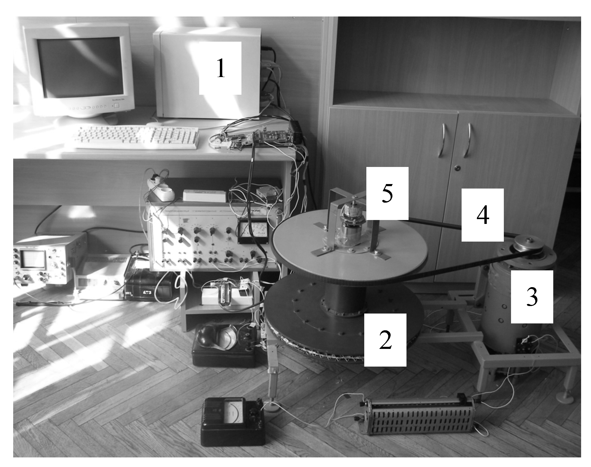
In order to confirm the efficiency of the proposed approach, studies were conducted on the validated simulation model and the real experimental installation (Figure 8); these are described in [6]. The approach consists of a computer control system (1), PMSM (2) and DC-machine load (3) connected through the belt (4).
Motor (2) is a multipolar SPMSM, where Ld ≈ Lq. It receives power from a custom inverter, built on ATmega 128, which is the core of a low-level control system that forms control signals to transistors drivers. The high-level control system was implemented on the PC (1), which allows us to dynamically change the regulator’s structure and parameters.
To provide speed feedback-loop, an absolute 12-bit Kübler 5862 rotary encoder was used. After processing position in Grey-code, this allowed us to calculate the motor’s speed. For the currents feedback loops, ABB EH050AP current sensors were used.
The parameters of the main SPMSM are the following: nH = 80 r/min, MH = 80 N∙M, Rs = 1.7143 Ohm, Φ = 0.1825 Wb, Jm = 2.43 kg·m2, pp = 38, Ld = 6.228 mH Lq = 6.468 mH, b = 0.1. As such, the respective control matrix (19) will look like this:
K = [ 0.27 0 0 0 0.271 0.072 0 0 0 ] .
The obtained dependences of rotation speed change and stator current projection on the q axis are shown in Figure 9.
Figure 9 shows results from the simulation model and the experimental installation. Due to limitations in experimental installation, particularly the limited power source, most studies were conducted on a low speed, which resulted in additional fluctuations in Figure 9.

7. Conclusions

The conducted analysis of literature sources allows us to assert that, in electric vehicle systems, the application of the theory of passive control is especially promising, as passive control is based on the physical laws of energy transfer and conversion; however, providing energy efficiency and energy flow management is a key challenge in electric vehicle systems.
The complexity of the synthesis of control system parameters inhibits the widespread application of the theory of passive control in electromechanical systems, which, in turn, creates a necessity to find new approaches capable of solving this problem.
The application of the classical theory of optimal control provides a way to synthesize parameter values of interconnection and damping matrices for energy-shaping control of linear and nonlinear electromechanical systems.
In contrast to many of the existing approaches, the application of the proposed approach for the synthesis of parameters of interconnections and damping matrices drives the transient characteristics of the system to be as desired, the appearance of which is determined by the given quality criterion of the system.
The results of the performed studies confirm the efficiency of the applied approach to the synthesis of control influences in both linear and nonlinear electromechanical systems.
The view of Riccati’s equation in terms of energy-shaping control has made it possible to form an optimality criterion that corresponds to the synthesized energy-shaping control.

Author Contributions

Conceptualization, A.L., Y.B., T.P. and J.K.; methodology, A.L., J.K., T.P. and L.K.; software, A.L. and Y.B., validation, A.L., J.K., T.P. and L.K.; formal analysis, A.L., J.K., T.P. and L.K.; investigation, A.L., J.K., T.P., Y.B. and L.K.; data curation, J.K. and L.K.; writing—original draft preparation, A.L. and Y.B.; writing—review and editing, T.P., J.K. and L.K.; visualization, T.P., J.K. and L.K.; supervision, A.L. and J.K.; project administration, T.P., J.K. and L.K. All authors have read and agreed to the published version of the manuscript.

Funding

This research received no external funding.

Institutional Review Board Statement

Not applicable.

Informed Consent Statement

Informed consent was obtained from all subjects involved in the study.

Data Availability Statement

Not applicable.

Conflicts of Interest

The authors declare no conflict of interest.

References

  1. Hassan, K. Khalil, Nonlinear Systems; Prentice Hall: New York, NY, USA, 2002; p. 768. [Google Scholar]
  2. Isidori, A. Nonlinear Control Systems; Springer: Berlin/Heidelberg, Germany, 1995; p. 550. [Google Scholar]
  3. Ortega, R.; Garcı’a-Canseco, E. Interconnection and damping assignment passivity-based control: A Survey. Eur. J. Control. 2004, 10, 432–450. [Google Scholar] [CrossRef]
  4. Morawiec, M.; Strankowski, P.; Lewicki, A.; Guziński, J.; Wilczyński, F. Feedback Control of Multiphase Induction Machines with Backstepping Technique. IEEE Trans. Ind. Electron. 2019, 67, 4305–4314. [Google Scholar] [CrossRef]
  5. Lascu, C.; Jafarzadeh, S.; Fadali, S.; Blaabjerg, F. Direct Torque Control with Feedback Linearization for Induction Motor Drives, IEEE Trans. Power Electron. 2017, 32, 2072–2080. [Google Scholar] [CrossRef]
  6. Hosseinzadeh, M.; Yazdanpanah, M. Robust adaptive passivity-based control of open-loop unstable affine non-linear systems subject to actuator saturation. IET Control Theory Appl. 2017, 11, 2731–2742. [Google Scholar] [CrossRef]
  7. Cheng, D.; Astolfi, A.; Ortega, R. On feedback equivalence to port controlled Hamiltonian systems. Syst. Control Lett. 2005, 54, 911–917. [Google Scholar] [CrossRef]
  8. Fossen, T.I.; Strand, J.P. Tutorial on nonlinear backstepping: Applications to ship control. Modeling Identif. Control 1999, 20, 83–135. [Google Scholar] [CrossRef] [Green Version]
  9. Fujimoto, K.; Sugie, T. Iterative learning control of Hamiltonian systems: I/O based optimal control approach. IEEE Trans. Autom. Control 2003, 48, 1756–1761. [Google Scholar] [CrossRef]
  10. Nguyen, L.V.; Thu, N.T. Fréchet Analysis and Sensitivity Relations for the Optimal Time Problem. IEEE Access 2020, 8, 46596–46604. [Google Scholar] [CrossRef]
  11. Ryalat, M.; Salim Damiri, H.; ElMoaqet, H.; AlRabadi, I. An Improved Passivity-based Control of Electrostatic MEMS Device. Micromachines 2020, 11, 688. [Google Scholar] [CrossRef] [PubMed]
  12. Pei, W.; Zhang, C. Port-controlled Hamiltonian optimal control and its application on electric vehicle drives. Chin. Autom. Congr. (CAC) 2017, 1831–1837. [Google Scholar] [CrossRef]
  13. Wen-hui, P.; Cheng-hui, Z.; Yan-jun, M. Feedback Hamilton realization and control of induction motor for electric vehicles. In Proceedings of the 32nd Chinese Control Conference, Xi’an, China, 26–28 July 2013; pp. 718–722. [Google Scholar]
  14. Shchur, I.; Rusek, A.; Biletskyi, Y. Energy-shaping optimal load control of PMSG in a stand-alone wind turbine as a port-controlled Hamiltonian system. Przegląd Elektrotechniczny (Electr. Rev.) 2014, 5, 50–55. [Google Scholar]
  15. Trang Vu, N.M.; Lefèvre, L. A connection between optimal control and IDA-PBC design. IFAC-PapersOnLine 2018, 51, 205–210. [Google Scholar]
  16. Chilan, C.M.; Conway, B.A. Optimal nonlinear control using Hamilton-Jacobi-Bellman viscosity solutions on unstructured grids. J. Guid. Control Dyn. 2020, 43, 30–38. [Google Scholar] [CrossRef]
  17. Lozynskyy, A.; Demkiv, L. Application of dynamic systems family for synthesis of fuzzy control for electromechanical systems. Adv. Electr. Electron. Eng. 2016, 14, 543–550. [Google Scholar]
  18. Zakaria, H.; Hamid, M.; Abdellatif, E.M.; Imane, A. Recent Advancements and Developments for Electric Vehicle Technology. In Proceedings of the 2019 International Conference of Computer Science and Renewable Energies (ICCSRE), Agadir, Morocco, 22–24 July 2019; pp. 1–6. [Google Scholar]
  19. Chellaswamy, C.; Ramesh, R. An intelligent energy management and control system for electric vehicle. In Proceedings of the 2014 IEEE International Conference on Advanced Communications, Control and Computing Technologies, Ramanathapuram, India, 8–10 May 2014; pp. 180–184. [Google Scholar]
  20. Veysi, M.; Aghaei, J.; Shasadeghi, M.; Razzaghi, R.; Bahrani, B.; Ryan, D.J. Energy-Efficient Speed Control of Electric Vehicles: Linear Matrix Inequality Approach. IEEE Trans. Veh. Technol. 2020, 69, 10469–10483. [Google Scholar] [CrossRef]
  21. Wicaksono, A.; Prihatmanto, A.S. Optimal control system design for electric vehicle. In Proceedings of the 2015 4th International Conference on Interactive Digital Media (ICIDM), Bandung, Indonesia, 1–5 December 2015; pp. 1–6. [Google Scholar]
  22. Vantsevich, V.; Lozynskyy, A.; Demkiv, L. A Wheel Rotational Velocity Control Strategy for An open-Link Locomotion Module. In Proceedings of the 19th International and 14th European-African Regional Conference of the ISTVS, Budapest, Hungary, 25–27 September 2017; pp. 1–18. [Google Scholar]
  23. Tiwari, A.; Jaga, O.P. Component selection for an electric vehicle: A review. In Proceedings of the International Conference on Computation of Power, Energy Information and Commuincation (ICCPEIC), Melmaruvathur, India, 22–23 March 2017; pp. 492–499. [Google Scholar]
  24. Cheng, K.W.E. Recent development on electric vehicles. In Proceedings of the 3rd International Conference on Power Electronics Systems and Applications (PESA), Hong Kong, China, 20–22 May 2009; pp. 1–5. [Google Scholar]
  25. Hu, D.; Hu, L.; Yan, Y. Optimization methodology for control strategy of parallel hybrid electric vehicle based on chaos prediction. AIP Adv. 2018, 8, 115305. [Google Scholar] [CrossRef] [Green Version]
  26. Shchur, I.; Biletskyi, Y. Battery Currents Limitation in Passivity Based Controlled Battery/Supercapacitor Hybrid Energy Storage System. In Proceedings of the 38th International Conference on Electronics and Nanotechnology, ELNANO, Kyiv, Ukraine, 24–26 April 2018; pp. 504–510. [Google Scholar]
  27. Lozynskyy, A.; Chaban, A.; Perzyński, T.; Szafraniec, A.; Kasha, L. Application of Fractional-Order Calculus to Improve the Mathematical Model of a Two-Mass System with a Long Shaft. Energies 2021, 14, 1854. [Google Scholar] [CrossRef]
  28. Shchur, I.; Biletskyi, Y. Energy-shaping control of two-mass electromechanical system in Hamilton representation. In Problems of Automatic Electric Drives. Theory and Application; Publishing House of Kremenchuk Mykhailo Ostohradskyi National University: Kremenchuk, Ukraine, 2012; pp. 435–438. (In Ukrainian) [Google Scholar]
Figure 1. Dependences of change in speeds of the first (green) and second (purple) masses during acceleration: (a) acceleration to the desired value; (b) the beginning of the acceleration process.
Energies 14 03711 g001
Figure 2. Dependence of the change in the twist angle Δϕ during the acceleration process.
Energies 14 03711 g002
Figure 3. Dependences of speed change in the first (green) and second (purple) masses during acceleration for γ = 0.5: (a) acceleration to the desired value; (b) the beginning of the acceleration.
Energies 14 03711 g003
Figure 4. Dependence of the twist angle change Δϕ during acceleration for γ = 0.5.
Energies 14 03711 g004
Figure 5. Dependences of speed change in the first (green) and second (purple) masses during acceleration for γ = 2: (a) acceleration to the desired value; (b) the beginning of the acceleration.
Energies 14 03711 g005
Figure 6. Dependence of the twist angle change Δϕ during acceleration for γ = 2.
Energies 14 03711 g006
Figure 7. Dependences of current iq (…) and speed of rotation ω (__) changes in the synthesized PMSM control system.
Energies 14 03711 g007
Figure 8. Experimental installation (1) computer control system; (2) SPMSM; (3) DC-machine load; (4) belt connection; (5) encoder.
Energies 14 03711 g008
Figure 9. Dependences of current i q (…) and speed of rotation ω (__) changes in the model and experimental installation.
Energies 14 03711 g009
Publisher’s Note: MDPI stays neutral with regard to jurisdictional claims in published maps and institutional affiliations.