Article

Dynamic Loads and Response of a Spar Buoy Wind Turbine with Pitch-Controlled Rotating Blades: An Experimental Study

1
Department of Engineering, University of Campania “Luigi Vanvitelli”, Via Roma, 29, 81031 Aversa, Italy
2
Inter-University National Consortium for Marine Sciences (CoNISMa), Piazzale Flaminio, 00144 Rome, Italy
3
Department of Engineering for Innovation, EUMER Campus Ecotekne, University of Salento, Via Monteroni, 73100 Lecce, Italy
4
School of Engineering, University College Cork, College Road, T12 K8AF Cork, Ireland
5
Marine Building, School of Engineering, University of Plymouth, Drake Circus, Plymouth PL4 8AA, UK
6
CNR-INM, Institute of Marine Engineering, Via di Vallerano 139, 00128 Rome, Italy
*
Author to whom correspondence should be addressed.
Energies 2021, 14(12), 3598; https://doi.org/10.3390/en14123598
Submission received: 22 May 2021 / Revised: 10 June 2021 / Accepted: 11 June 2021 / Published: 17 June 2021

Abstract

:
New large-scale laboratory data are presented on a physical model of a spar buoy wind turbine with angular motion of control surfaces implemented (pitch control). The peculiarity of this type of rotating blade represents an essential aspect when studying floating offshore wind structures. Experiments were designed specifically to compare different operational environmental conditions in terms of wave steepness and wind speed. Results discussed here were derived from an analysis of only a part of the whole dataset. Consistent with recent small-scale experiments, data clearly show that the waves contributed to most of the model motions and mooring loads. A significant nonlinear behavior for sway, roll and yaw has been detected, whereas an increase in the wave period makes the wind speed less influential for surge, heave and pitch. In general, as the steepness increases, the oscillations decrease. However, higher wind speed does not mean greater platform motions. Data also indicate a significant role of the blade rotation in the turbine thrust, nacelle dynamic forces and power in six degrees of freedom. Certain pairs of wind speed-wave steepness are particularly unfavorable, since the first harmonic of the rotor (coupled to the first wave harmonic) causes the thrust force to be larger than that in more energetic sea states. The experiments suggest that the inclusion of pitch-controlled, variable-speed blades in physical (and numerical) tests on such types of structures is crucial, highlighting the importance of pitch motion as an important design factor.

1. Introduction

The European SET-Plan (European Strategic Energy Technology Plan) has stated the necessity of diverting its energy supply towards the use of an energy system that reduces carbon emissions, developing competitive technologies that exploit renewable sources [1].
Subsequently, through the Green Deal Plan, the European Community is committed to achieving climate neutrality by 2050, transforming Europe into a sustainable society [2]. In these plans, particular importance is given to marine renewable energies, derived from wind, wave and solar resources, currents and tides, which have become essential for a complete energy transition towards clean energy. Among these, offshore renewable energies could potentially increase future power generation in a massive and affordable way [3].
Wind energy plays a key role in the offshore sector. Currently, the most widespread technology is that of a fixed foundation [4], mainly the monopile type. The choice of this technology is linked to the depth of the seabed; it is typically used in “shallow waters” of 0–25 m. As the depth of the seabed increases, needing tripod and jacket foundations, it is necessary to switch to floating technology. To fully exploit the resources, it is necessary to move further offshore; however, in many cases, the depths are too deep at even a few kilometers from the coast, so the need for a reliable floating technology is very important [5]. For this reason, research and industry are striving to develop new floating technologies and consolidate existing ones. Europe’s floating wind fleet is the largest worldwide (70%) producing a total of 45 MW by the end of 2019 [4]. Demonstration projects have tested different floating concepts [6], sometimes associating wind turbines with wave energy converters [7,8,9] with the objective to reducing costs or upscaling previous model-scale devices. However, in other countries, the feasibility of this type of device has been evaluated [10,11].
FOWT are usually classified into three categories based on the static stability mechanism. Semi-submersible structures achieve stability by balancing weight and buoyancy of the floater in operational conditions; tension leg platforms are stable due to a tensioned tendon mooring system; and spar buoy platforms are stable depending on the relative location between the center of buoyancy and the center of gravity. However, the last of these are relatively easy to build if compared them to TLPs and semi-submersibles and they are known for a lower dynamic response per displacement [12].
To date, the design of FOWTs is founded on three basic tools: semi-empirical formulations, physical modeling and numerical modeling. In particular, a combination of physical and numerical models to analyze the complexity in the hydrodynamics, aerodynamics and structural stresses it is being increasingly used. Nevertheless, physical modeling in a laboratory is still the worldwide accepted standard for the design of a FOWT structure, especially when the “proof of concept” or a very detailed study on the FOWT’s behavior is required. It is worth considering that the use of small-scale models is not always sufficient to obtain an accurate structural response of such complex structures. A clear understanding of scaling laws applied to FOWT design remain a setback [13,14,15,16,17,18]. However, simplified Froude-scaled experiments represent a necessary path to large or full-scale prototypes, and are essential to have complete knowledge of the overall wind/wave-structure interaction phenomena.
The first FOWT pilot, the Hywind Demo, was installed almost 12 years ago, 10 km away from the southwest coastline of Norway in 2009 by Statoil (now Equinor) [19]. Although it only has a capacity of 2.3 MW, it achieved a historic breakthrough in the operation of FOWTs.
Since then, large efforts to better understand the phenomena involved in the dynamic behavior of the spar buoy FOWT have been made by researchers and industries [20].
Based on the Hywind platform prototype, a reference model with a NREL 5 MW wind turbine installed, was developed [21]. Through this model, it has been possible to summarize the main differences between the existing numerical codes and to define shared procedures for designing FOWTs [22,23]. Moreover, experimental tests carried out on the basin at the Maritime Research Institute Netherlands (MARIN) with a 1:50 Froude-scaled model [24,25] allowed to calibrate and validate the FAST offshore floating simulation tool [26].
Results obtained from numerical models needed to be further validated with laboratory tests. For this reason, since 2006, various campaigns have been carried out. The first experiments were performed at MARINTEK in Trondheim, by means of a 1:47 Froude-scaled model subjected to coupled wind and wave loads [27,28]. The tests were focused on the dynamic behavior of the system in a 100-year wave condition, in an above-rated wind speed and in average wave conditions, with a below-rated wind speed. The comparison between numerical models showed similar induced wave motions; however, the responses around natural frequencies were overestimated in simulations.
With a larger model scale, 1:22.5, other tests were carried out in Japan by Utsunomiya et al. [29]. The spar buoy was invested using regular and irregular waves; however, the distribution of the wind load on the rotor was simplified by a constant horizontal force on the tower.
After performing free decay, regular and irregular wave tests on a 1:100 scaled OC3-Hywind concept, experimental results were shown to be in accordance with the numerical ones derived from 3Dfloat and ANSYS by Myhr et al. [30]; however, smaller motions were obtained during experiments.
Another comparison between experimental tests and numerical model (trough OrcaFlex) was performed on a 1:100 scale wind turbine mounted on a stepped spar with four mooring lines [31]. In particular, the hydrodynamic response under regular and irregular waves was investigated, and a good agreement in terms of natural frequencies and motion response was obtained.
Nallayarasu and Saravanapriya [32,33] investigated the response of a 1:75 model in 250 m deep water under regular and irregular waves, with different mooring systems and angle. They focused on the optimization of the mooring lines configuration in operational conditions and verified data numerically (through Ansys AQWA).
More recently, Grupee et al. (2014), Duan et al. (2016), Ahn e Shin (2019) and Tomasicchio et al. (2018) tested scaled OC3-Spar FOWTs under wind and wave loads. In [34], wave basin tests were conducted, generating wave and wind conditions, however, the misalignment between the two was not studied. In [35], a study on the RAOs of a 1:50 OC3 model was carried out, showing that, in yaw, it was strongly influenced by the rotor rotation. Though, the tower was not properly modeled, and the rotor was wind-driven.
In two studies [36,37], the capture of the spar platform motions allowed to evaluate the RAOs. In particular, in [37] the downscaling of the model (1:128) disabled the full matching of the blades with the prototype ones; however, the numerical simulation showed a slight agreement with the experimental tests in regular and irregular waves.
A considerable amount of sea states was tested on a 1:40 model of OC3-Hywind spar in 2014, as part of Hydralab IV. Experimental results are reported in [38], however in this campaign the wind loads were simulated through a static weight. These tests, carried out in the DHI Offshore Wave Basin in Hørsholm (Denmark), were preliminarily compared with the responses obtained through the FAST code [39].
In order to investigate the behavior of an OC3-Spar in a real environment, Ruzzo et al. [40] installed a 1:30 scale model at sea at the Natural Ocean Engineering Laboratory (NOEL) in Reggio Calabria (Italy).
When designing a spar buoy wind turbine, the limitation of pitch motion is crucial. Large pitch motions could undermine the gyroscopic stability of the hull because of the instantaneous change in the relative wind direction on the rotor [24]. For this reason, the use of pitch control becomes of primary importance [12].
The effect of a collective pitch control under a wind generator with rotating blades is investigated in this article. Laboratory tests are related to a 1:40 OC3-spar buoy scaled model. Experimental campaign was carried out at the Danish Hydraulic Institute -DHI in Hørsholm (Denmark) within the framework of the EU-Hydralab+ project, in March–April 2019. Its main aim was to compare the dynamic and hydrodynamic responses of the FOWT under different combined action of wind and wave loads in the presence of a wind generator. The data provides a comprehensive and controlled series of test for calibration and validation of numerical models.
This paper extends the preliminary results obtained in [41]. Special attention has been paid on the response under different wind loads of the structure subjected to waves having increasing steepness. It is organized as follows: in Section 2, details of experimental instrumentation, set-up and test program are described. Section 3 reports the results and discussion obtained through examining the natural frequencies of the structure and its response under regular waves in the frequency domain.
In particular, results are focused on the DoFs of the structure, on the forces and acceleration on the nacelle, on the thrust force, and on the mooring line response. Finally, in Section 4, some conclusions and remarks are drawn.

2. Experimental Set-Up and Procedures

In Section 2.1, the test facility, the instrumentation equipping the structure and the configuration used during tests are described. The floating wind turbine investigated in this work was composed of three main parts, discussed in detail in Section 2.2:
  • the wind turbine,
  • the floater (spar buoy),
  • the mooring system.
In Section 2.3, the overall test program is discussed, focusing on the analyzed test in Section 2.4.

2.1. Test Facility and Instrumentation

The DHI wave basin was 20 m long, 30 m wide and 3 m deep. In the center of the wave basin, a 3 m × 3 m pit with a depth of 6 m was installed. By placing the tested floating structure in the middle of this pit, deep water conditions occurred, allowing to simulate real scale behavior.
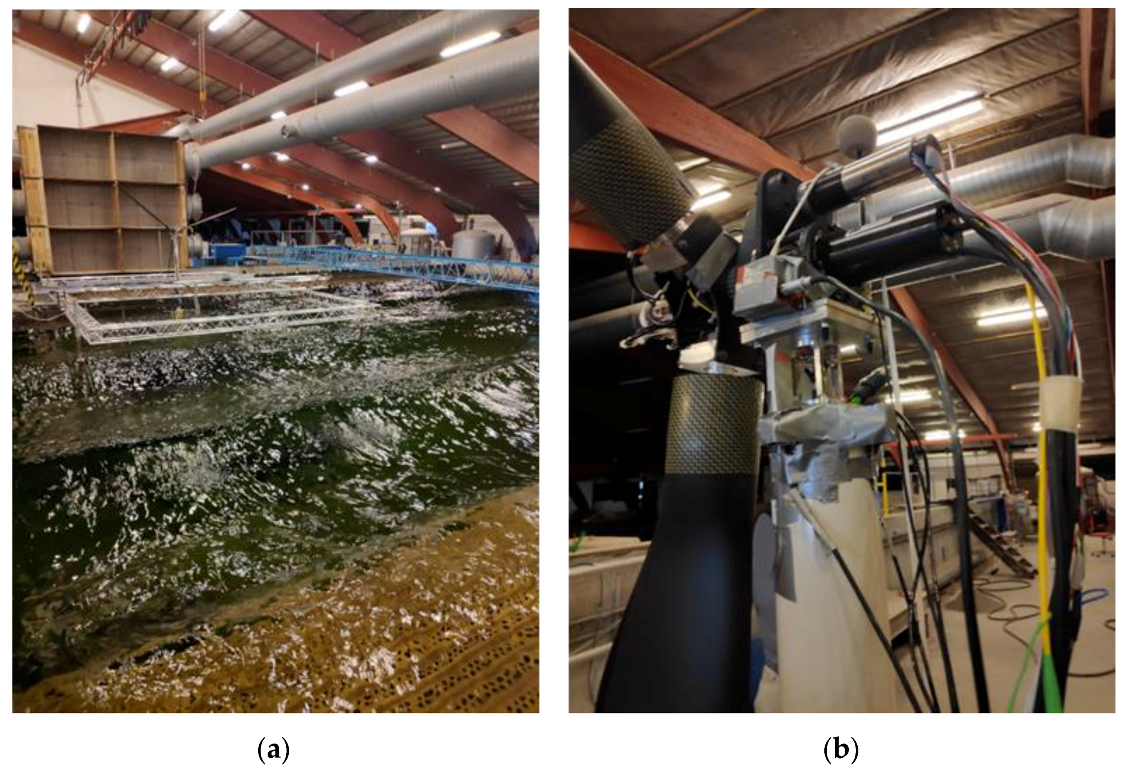
Regular and irregular waves, both unidirectional and directional, were generated by sixty individually controlled flaps equipping the wave maker. To minimize reflection, a 6.5 m long sloping wave absorber was located opposite to the wave maker. Wind loads instead, were ensured by six wind generators placed in front of the model (Figure 1a).
The origin of the global coordinate system was chosen to be on the right corner of the basin in correspondence with the first flap, with a positive x-axis according to the wave propagation direction.
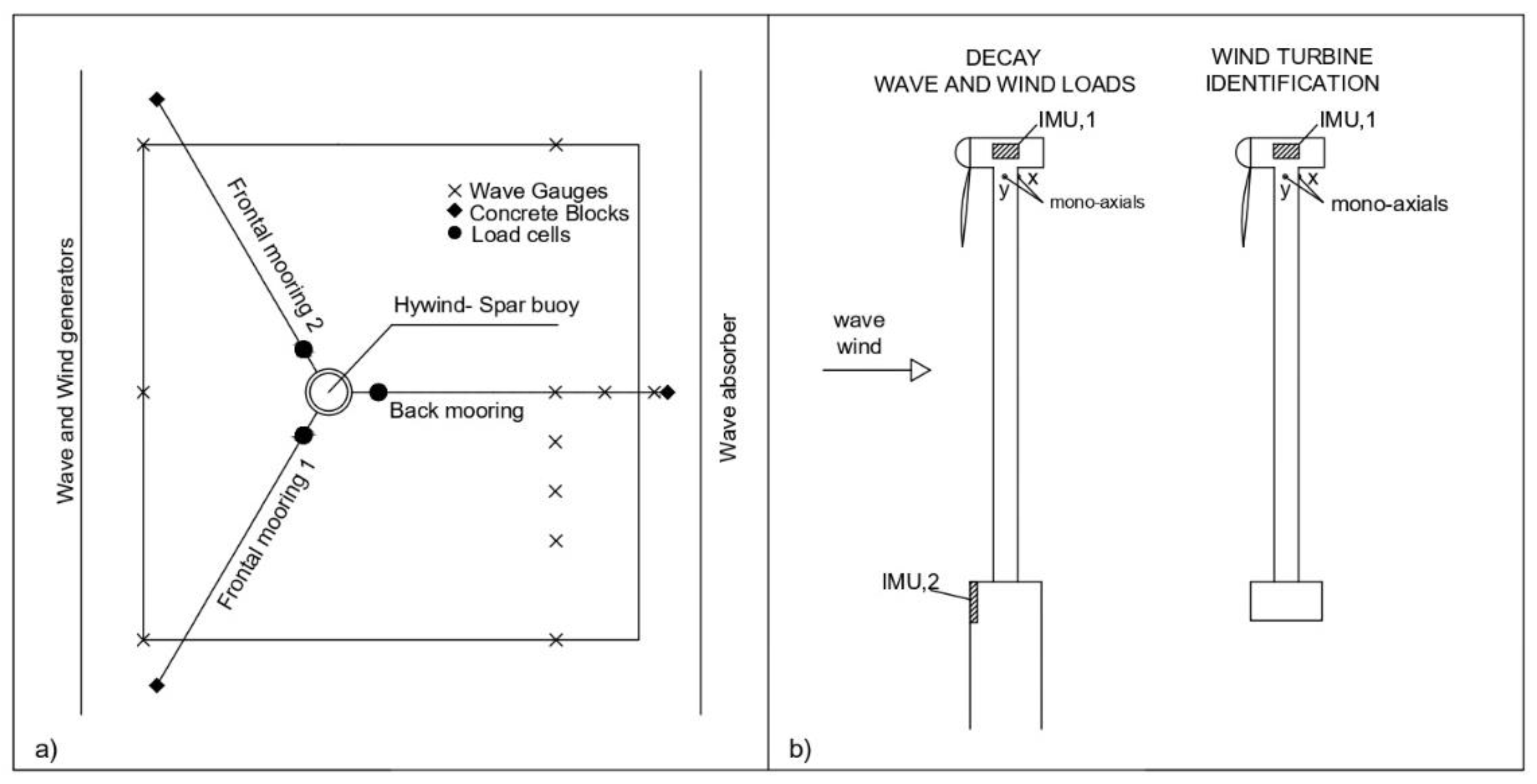
The free surface elevation was captured by eleven wave gauges placed around the structure (Figure 2a). Three of these were placed in row, perpendicular to the wave direction, 1.5 m before the structure. A row of six gauges was placed 1 m behind it. Moreover, two additional wave gauges were placed behind the model in order to estimate the incident and reflected waves [42]. An anemometer measuring wind speed was placed 1.5 m before the structure. Concerning the floating structure, a very large number of sensors was used to measure its behavior (Figure 1b).
In the wind turbine rotor, an encoder allowed the measurement of the angular velocity of the generator, and, beside it, enabled to track the reference for the blade’s pitch. An inertial platform unit (IMU), measuring translational and angular acceleration along the three main axes, was placed in correspondence with the nacelle. The RNA (rotor–nacelle-assembly) system was connected to the tower by means of a four-component force gauge, measuring force and moments along the x (orthogonal to rotor) and y (parallel to rotor) directions. Immediately below the tower, two mono-axial accelerometers were placed, capturing accelerations along the global x and y axes.
The upper part of the tower was directly connected to the spar buoy platform, where another inertial platform captured the accelerations along the axes.
The spar buoy was kept in position by the mooring system, which was mainly composed of three mooring lines; on each of these, a load cell measuring tension due to the spar motion was placed (Figure 2a).
Translations and rotations of the overall structure were recorded through a Qualisys tracking system, consisting of two cameras emitting infrared light, reflected by 40 mm diameter spherical markers. The markers were mounted both at the connection between tower and the spar buoy, and in correspondence with the RNA. All observed data were synchronized by the DHI Wave Synthesizer.
When studying the behavior of the upper part (tower and RNA) as a separate body (i.e., when wind turbine identification and hammer tests were carried out), IMUs and mono-axials accelerometers were differently positioned, as shown in Figure 2b.

2.2. Model Design

In this subsection the three components of the floating structure are discussed in detail.

2.2.1. Wind Turbine

The wind turbine was designed, downscaling (1:40) the reference model NREL 5 MW [43], in accordance with Froude similarity rule. Nevertheless, in order to match the reference thrust and torque, the rotor was defined as a geometrical upscale of the wind turbine model developed by Politecnico di Milano [44], a wind turbine model of the DTU10MW reference wind turbine [45]. The scaled characteristics are reported in Table 1.
Concerning the airfoils, SD7032s were chosen, allowing to have better performance at lower Reynolds number characterizing the airfoil aerodynamic.
Starting from NREL 5 MW control system, the Hydralab+ wind turbine was based on variable speed-collective pitch control strategy, allowing the turbine to operate in different conditions. The blade pitch actuator operated the rotation of the rotor blades about their pitch axis. With the blade pitch angle set at the full-power angle, maximum power is extracted from the incident wind flow field. As the blade pitch angle is rotated toward the full feather position, the blades become less efficient at converting the power in the wind flow field to shaft power. In particular, the operating area of the wind turbine can be divided in three regions depending on the wind speed value. These are:
  • Region 1, below the cut-in wind speed, used for the start-up of the wind turbine.
  • Region 2, between cut-in and rated wind speed, where the turbine worked at partial load. The blade pitch was fixed at minimum, while the turbine was regulated at variable speed through the torque controller, in order to optimize the power extraction.
  • Region 3, extending from rated wind speed to cut-off, in which the turbine worked at full load. The generator torque was kept at the rated value, the turbine operation was regulated by blade pitch-to-feather controller, in order to regulate rotor speed and power.

2.2.2. Floating Platform

The floating platform supporting the wind turbine was a Froude 1:40 downscaled version of the OC3-Hywind spar buoy designed in 2010 by Jonkman [21].
The spar buoy, as used in the previous experimental campaign [39], was composed of three main sections:
  • the upper cylinder, with a length of 400 mm and an outer diameter of 162.5 mm;
  • the lower cylinder, comprehending most of the height of the spar, 2.6 m, and an outer diameter of 235 mm;
  • the tapered transition part, connecting the upper and the lower cylinder and developing for 200 mm.
Furthermore, a 100 mm removable bottom filled with lead grains was added to the lower cylinder. Its main function was to reach the draft of 3 m and the center of gravity of 2.25 m below the still water level (SWL hereinafter).
A removable bottom of 100 mm in height was used to place an additional ballast. The downscaled properties of the spar buoy are listed in Table 2.

2.2.3. Mooring System

The mooring system was composed of three mooring lines, two in front of and one behind the model, forming a horizontal angle of 120° each other. As already simplified in the OC3-project [21], the original delta connections provided for Statoil’s Hywind catenary system were eliminated and each mooring line was connected to the floater through a collar at a vertical distance of 1.75 m from the SWL.
The limited water depth of the basin led to an additional simplification, reducing each mooring line in a series of seven springs. These springs adequately pretensioned, allowed to obtain the same surge and sway behavior and the same center of gravity of the OC3-Project mooring system. Following the springs, a rope composed of Dyneema fiber connected each mooring line to an anchor (concrete block) resting on the basin floor 3 m below the SWL. The properties of the mooring system are summarized in Table 3.

2.3. Test Program

The experimental tests were carried out considering different wind and wave conditions. In the following subsections, for each type of test, the motivation and experimental procedure are explained; moreover, tables containing the test program are presented.

2.3.1. Wave Calibration and Wind Turbine Set-Up

Before performing tests under wind and wave loads, calibration of the exciting forces was needed. Concerning the calibration of the basin, both regular and irregular waves that would have been tested later were run. Clearly, in this phase, the structure was not present in the basin. It is worth noting that, for regular waves, tests had a duration from 2 to 4 min (time necessary to have around 100 waves). The time duration for the irregular tests was instead determined to fit a number of waves of around 1000. For instance, extreme conditions duration time was between 20 and 30 min [46,47].
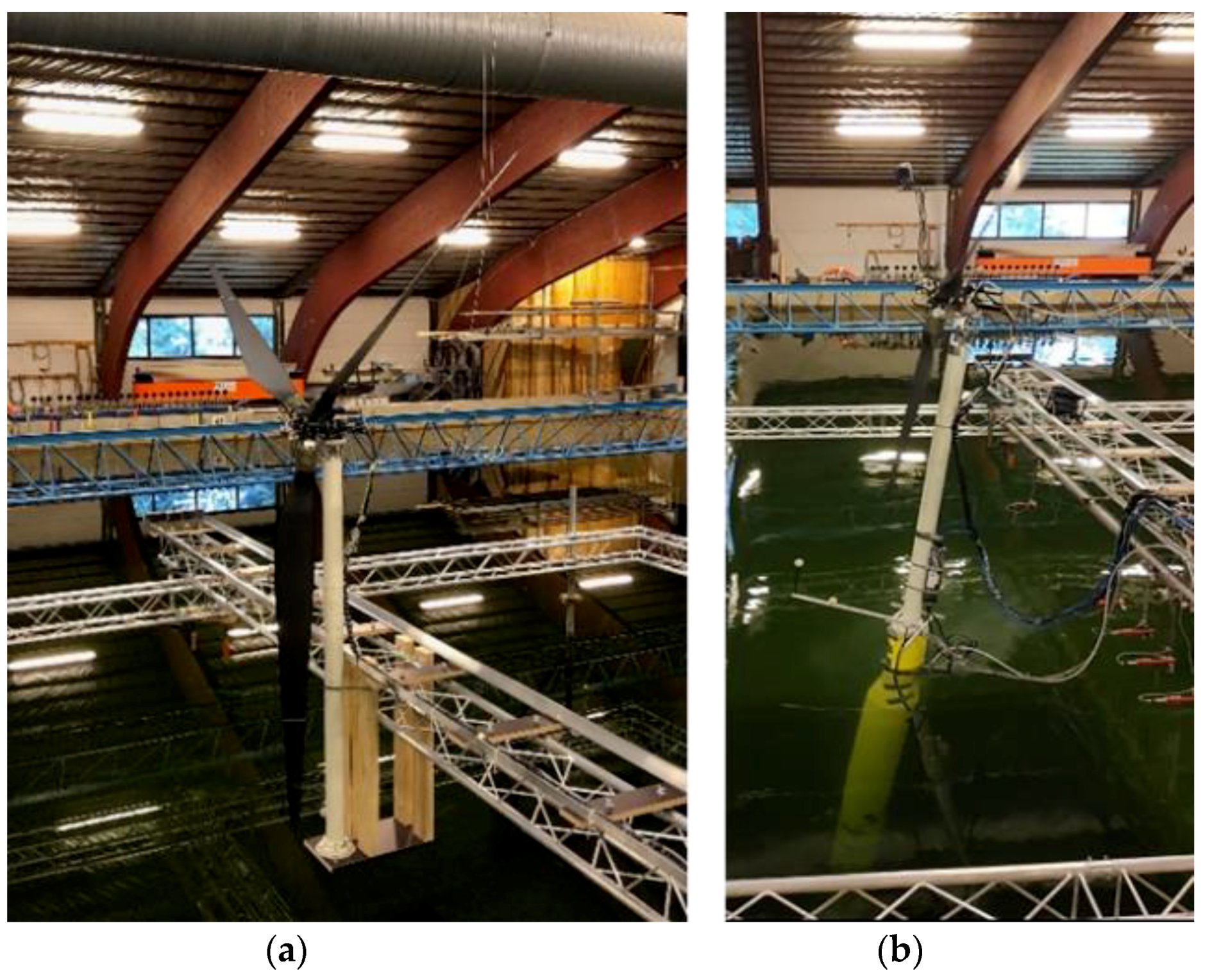
To evaluate the contribution of the wind turbine in the whole structure response, two sets of tests were conducted. As first, the turbine was tested outside of the water, by linking the upper structure to the aluminum cage placed in front of the wind generator (defined as wind turbine set-up test, as in Figure 3a. Secondly, the upper structure was mounted on the spar buoy and only wind impacted on it (referred as only wind tests, as in Figure 3b. In both this configuration all the wind conditions, without generating waves, were tested. Changes in wind condition allowed to evaluate the different controlling behavior of the turbine.

2.3.2. Decay Test

Decay tests were carried out to define the natural frequencies and total system damping for each degree of freedom (hereinafter DoF or DoFs when plural). These were run with and without the mooring lines, where possible. In addition, different wind speeds were applied while performing tests, underlying the contribution of wind damping (Table 4).
The time duration for each test depended on the number of representative cycles to obtain the damping and the average period of the oscillations. For this reason, they were repeated several times.

2.3.3. Wind Turbine Natural Frequency and Damping Identification

Natural frequency and damping ratios of the wind turbine were evaluated considering the right-side configuration of Figure 2. (a) Plan view of the instruments around the structure. (b) Sketch of the inertial platforms and mono-axials accelerometers distribution during tests.
For both the x and y directions, the wind turbine was pulled at the tower top, then released, and oscillations were recorded through accelerometers. These tests are reported in Table 5.

2.4. Wind and Wave Conditions

Among all the tests generated during the experimental campaign, the present work focuses on a particular set of regular wave conditions (characterized by significant wave height H, mean wave period T and wave direction DD) as reported in Table 6. First, the structure was only subjected to waves without generation of wind (referred as Regular no-wind in the following). Then, two wind conditions were added: with a wind speed (WS) of 1.45 m/s (Regular Below rated condition) and with a speed of 1.85 m/s (indicated as Regular Above rated).
Keeping the wave height constant, three period were considered: T = 1.1 s, T = 1.6 s and T = 2.2 s, resulting in three different steepnesses kA (being k the angular wave number and A the first-order wave amplitude): kA = 0.43, kA = 0.20 and kA = 0.11, respectively. The response of the structure under these loads were analyzed in terms of displacement, acceleration, forces and loads.

3. Results and Discussion

This section aims to illustrate and comment on the results obtained by elaborating data derived from instruments positioned on the structure. In the first subsection, natural frequencies associated with the structure are evaluated; in the second one, a frequency domain analysis is performed, subjecting the structure to the abovementioned set of regular wave tests.

3.1. Natural Frequency Identification

For a full comprehension of the dynamic behavior of the examined structure, all the natural frequencies need to be identified. In this subsection, wind turbine oscillation and hammer tests are analyzed through the mono-axials accelerometers positioned on the structure. Free decay tests instead are evaluated by considering the registered Qualisys tracking system motion and rotation.

3.1.1. Wind Turbine

Wind turbine natural frequency identification tests results are shown in Figure 4, where the time history of free oscillations in terms of accelerations (m/s2) along the x and y axes, along with the relative spectra, are reported. As previously described, these tests were carried out considering the right-side configuration of Figure 2b, consisting of the tower equipped with a nacelle, rotor and blades.
Defining Tm as the average value of periods between two succeeding zero down crossing along the decaying curve, the natural frequency is found by inverting this value. StdTm, instead, represents the standard deviation of the average period Tm.
In Table 7 the natural frequency along the x and y directions are reported. In the first direction, fn = 2.136 Hz; along y, instead the natural frequency is slightly higher, resulting in 2.209 Hz.

3.1.2. Free Decay

An analysis of free decay was conducted for all the DoFs, evaluating both the influence of mooring lines and the influence of wind speed, through the variation on natural frequency. Results are, respectively, reported in Table 8 and Table 9.
Starting from the evaluation of mooring lines influence, it is worth noting that the comparison on results can be achieved only for the DoFs presenting a hydrodynamic restoring, i.e., heave, roll and pitch, where it was possible to perform free decay tests in absence of mooring lines. Clearly, these tests were in absence of wind. As expected, the presence of the mooring slightly increases the natural frequency (fn) of the system in all evaluated directions. Defining Δfn as the difference in percentage between the natural frequency of moored system and un-moored one (Equation (1)), the highest variation was registered in pitch and the lowest in roll.
Δ f n = ( f n , moored f n , unmoored ) f n , moored · 100
Regarding the influence of the wind speed, the results in terms of natural frequency are reported in Table 9. In surge, starting with a value of 0.085 Hz for the first condition (no wind acting on the structure), the natural frequency decreases to 0.079 Hz with a nominal wind speed of 1.25 m/s. However, increasing the wind speed, the natural frequency continues to decrease slightly.
A similar behavior was found in pitch where the highest natural frequency of 0.21 Hz was reached in absence of wind. The rotation of the blades under all the wind speeds leads to a decreasing in natural frequency to an average value of 0.183 Hz.
In sway and roll instead, decay tests were not performed in presence of wind because its influence on the natural frequency was expected to be not significant. For the translational DoF, the measured natural frequency is of 0.067 Hz, in roll instead it has a value of 0.185 Hz.
In heave, in absence of wind and whichever its speed, the natural frequency is assessed on the same value of 0.22 Hz.
In yaw, already at the lower nominal wind speed of 1.25 m/s, the structure is unable to oscillate, reaching the critical damping. Further details on damping coefficient can be found in [41].

3.2. Frequency Domain Analysis Results

In this subsection frequency domain analysis of wind-wave-structure interaction is performed. In particular, the thrust forces, the motion of the structure in the six DoFs, the dynamic forces and the associated accelerations on the nacelle along the x and y axes are evaluated. Moreover, the tension of the mooring lines is investigated.
The analysis of the frequency response was carried out with the structure subjected to regular waves with different steepnesses and subjected to an increasing wind speed (as described in Section 2.4).

3.2.1. Thrust Force

The thrust force FThrust (Equation (2)) has been evaluated as the difference of the Force acting on the Nacelle along x-direction, defined as Fx, and the acceleration multiplying the nacelle mass, defined as m. It is mathematically expressed as:
F Thrust = F x m · a x
In particular, on the left-hand side of Figure 5, the thrust force for the three wave conditions is associated with a wind of 1.45 m/s, on the right-hand side instead, the wind speed assumes a value of 1.85 m/s.
For both wind speeds, the frequency domain analysis highlighted that the main component of the overall response is associated with the first wave harmonic. In Table 10 the measured frequencies associated with the first, second and third harmonics of the three different wave conditions are reported. It is worth noting that, the increasing of the wind speeds leads to an increasing of the energy content, which, however, assumes the major value with the highest wave period and gradually decrease with it.
Frequency domain analysis, moreover, allowed to identify other frequencies on the spectra. In fact, it is clearly highlighted as the frequency response is significantly affected from the rotor velocity. As reported in Table 11 first and third harmonic of the rotor velocity are excited. It is interesting to point out how in the above-rated condition the energy content of the first rotor harmonic associated with the intermediate sea state (red line) is relatively higher than in the more energetic sea state—this behavior should be attributable to the coupling between both the first wave harmonic of the wave and of the rotor.

3.2.2. Motion of the Structure

The motions of the structure in terms of displacements and rotations as analyzed here, were obtained by elaborating Qualisys tracking system’s data recorded on the floater.
In Figure 6, Figure 7 and Figure 8 are respectively reported the motions of the structure in the six DoFs under no wind condition (WS = 0 m/s), below-rated condition (WS = 1.45 m/s) and above-rated condition (WS = 1.85 m/s).
When the structure was subjected only to wave loads, in surge, pitch and heave, the first wave harmonics were clearly identified for all the wave steepnesses, showing the greatest power content with the lowest value of the steepness kA = 0.11. The power content then decreased with the increasing steepness. In heave, the minimum power content was registered. In surge, a slight contribution of surge and pitch natural frequency is detected for kA = 0.11.
In sway and roll, the first wave harmonics were still identified, although for the case of kA = 0.43 it was imperceptible. It is worth noting that for the three values of the steepness, in the translational DoF, sway and roll natural frequencies were detected, while, in roll only, the natural frequency associated with the same DoF was found.
Additionally, in yaw the main power content may be attributable to the first wave harmonics; however, the steepness influence was more significant. Indeed, from the greatest value in the case of kA = 0.11, the power content became negligible when kA = 0.43.
In Figure 7, wind with a speed of 1.45 m/s was added to the regular waves. Substantially, the structural behavior was the same as for the case of no wind; however, although the wave harmonics still were found in all the DoFs and for all the wave steepnesses, several differences were highlighted. In pitch, a low contribution of the same natural frequency occurred, in roll instead, the power content associated with the same DoF became more pronounced respect to the first wave harmonic in the case of kA = 0.11. In translation along the z-axis, all the waves evidenced a contribution of the heave natural frequency. In sway and yaw, when the structure was subject to all the wave steepnesses, a power content at 1.12 Hz was measured, having a higher value with kA = 0.11 and the lowest with kA = 0.43.
Figure 8 shows the motion of the structure under regular waves associated with the above-rated wind speed. The coupling between surge and pitch results in low power content associated with their natural frequency. In particular, in surge, both natural frequencies were found, while in pitch only its natural frequency was identified. In heave, besides the wave harmonics and the heave natural frequency, the three wave steepnesses presented a slight peak at a frequency of 1.25 Hz. The same peak was found in sway, roll and yaw. In the last DoF, the natural yaw frequency was identified, although with a small power content; a slighter one was associated with roll natural frequency.

3.2.3. Dynamic Forces and Accelerations on Nacelle

In this subsection dynamic forces, recorded by the force gauge, in correspondence of the nacelle and the relative acceleration, deriving from the mono-axials accelerometers, are analyzed. In Figure 9, Figure 10 and Figure 11, forces and acceleration along x and y axes, named Fx, Fy, ax, ay, are reported, respectively, for no wind condition, below and above-rated wind speed.
In the first figure, looking at the x-direction, which corresponds to the wave propagation direction, both for Fx and ax the structure is almost excited exclusively by the first wave harmonic. It is interesting to note that the energy content is higher in the intermediate sea state, characterized by kA = 0.20. However, a low amount of power may be attributable to the second and the third frequency.
Comparing the obtained response along the x direction with the one along y, it can be noticed how the power on the second one is considerably lower. This, as expected, can be ascribed to the wave direction propagation.
However, focusing on the response along y-direction when kA = 0.43 and kA = 0.11, a similar behavior is found, both for forces and accelerations. Indeed, although they are always dominated by the first wave frequency, after a minimum response at the second wave harmonic, the energy associated with third one is relevant.
Nevertheless, when the structure is invested by a kA = 0.20 wave, the highest percentage of contribution is associated with the first and the second wave harmonic; the third one still contributes, but in a minor way. Furthermore, in both Fy and ay, this condition presents a frequency response at the value of 0.185 Hz, corresponding to the roll natural frequency.
If one would study the potential wind influence on the structure behavior, Figure 10 and Figure 11 needs to be commented.
Starting from the below-rated wind speed of 1.45 m/s, along the x direction both the force and acceleration major component in terms of power are represented by the first wave harmonic corresponding to each of the three wave conditions analyzed. However, the intermediate sea state shows a greater contribution respect to the other wave loads. Furthermore, in the force case, the components at 1.12 Hz and 3.36 Hz are found for all the wave conditions.
Along y-axis instead, the behavior completely changes. Indeed, the major contribution appears, for all wave loads, at a frequency of 1.12 Hz, presenting a minor effect in correspondence of 2.24 Hz and 3.36 Hz. In this case, the first wave contribution assumes minimum relevance if one considers forces. Accelerations instead presents a comparable wave energy component, that excite the structure in first, second and third harmonic, in all the conditions. Furthermore, roll natural frequency is found in both forces and accelerations.
A similar behavior is found in the above-rated wind speed (Figure 11). However, along x-direction, the frequency components common to each wave conditions are found at 1.25 Hz, 2.5 Hz and 3.75 Hz. The first two are also found in force and acceleration along y-direction, becoming definitively dominant in the force case. Second and third wave harmonic contributions are found for each wave loads in the acceleration along y-axis, although being smaller than the rotor frequency. Additionally, in this case, along y, the natural roll frequency is identified.
Considering the difference between the three wind conditions, for each wave associated, it can be noticed that an increasing in the wind speeds leads to a massive increase in the force along y-direction; in particular, the energy content more than doubles when the wind passes from the below to the above-rated condition. Acceleration growth along the same direction instead, doubles when the wind impact on the structure respect to the no-wind condition; despite this, it is not influenced by the value of the wind speed.

3.2.4. Mooring Response

In Figure 12 mooring lines tension response for all the load conditions is reported both for the mooring line placed in front of the spar (front mooring) and for the one placed on its back (back mooring).
It is clearly visible that the most powerful response is obtained at the first wave frequency for all the wind speeds, for both moorings. Moreover, it is worth noting that, the higher the wave period, the higher the response, determining a proportionality between wave period and dynamic loads. This behavior, although observed for both mooring lines, is characterized by a more powerful response in the case of the back one.
In no-wind condition, for the frontal mooring, the surge natural frequency is identified. It becomes more evident when considering the intermediate sea state, presenting a power content three times higher than the first wave frequency component.
The same natural frequency is identified in the response of the frontal line in below-rated conditions, although presenting a low power content. In this case, the back mooring shows a slight contribution in the overall response of the second wave frequency component for all the evaluated cases.
When increasing the wind speed to the above-rated condition, in the frontal mooring is once again identified the surge natural frequency. In the back mooring, instead, although remaining the first wave harmonic the principal component, the surge natural frequency becomes more evident with the increasing wave period. The intermediate sea state shows a behavior quite unexpected, reinforcing the understanding that under certain wave steepness the nonlinear effects could be more evident.

4. Conclusions and Recommendations

The research describes the experimental tests conducted at the Danish Hydraulic Institute in Hørsholm (Denmark). The test program was designed to investigate the difference in dynamic response of a spar buoy wind turbine under no wind, below and above-rated wind speed, and three values of wave steepness. The peculiarity of the experimental campaign is that the 1:40 Froude-scaled physical model was equipped with pitch-controlled, variable-speed blades. The control effectors (actuators) execute motion in response to commands from the control computer. Three different setups of pitch were selected, according to wind conditions. The observations of the model response enable some general conclusions to be drawn.
As expected, the waves contributed to the majority of the model motions, and their power decreases with increasing steepness.
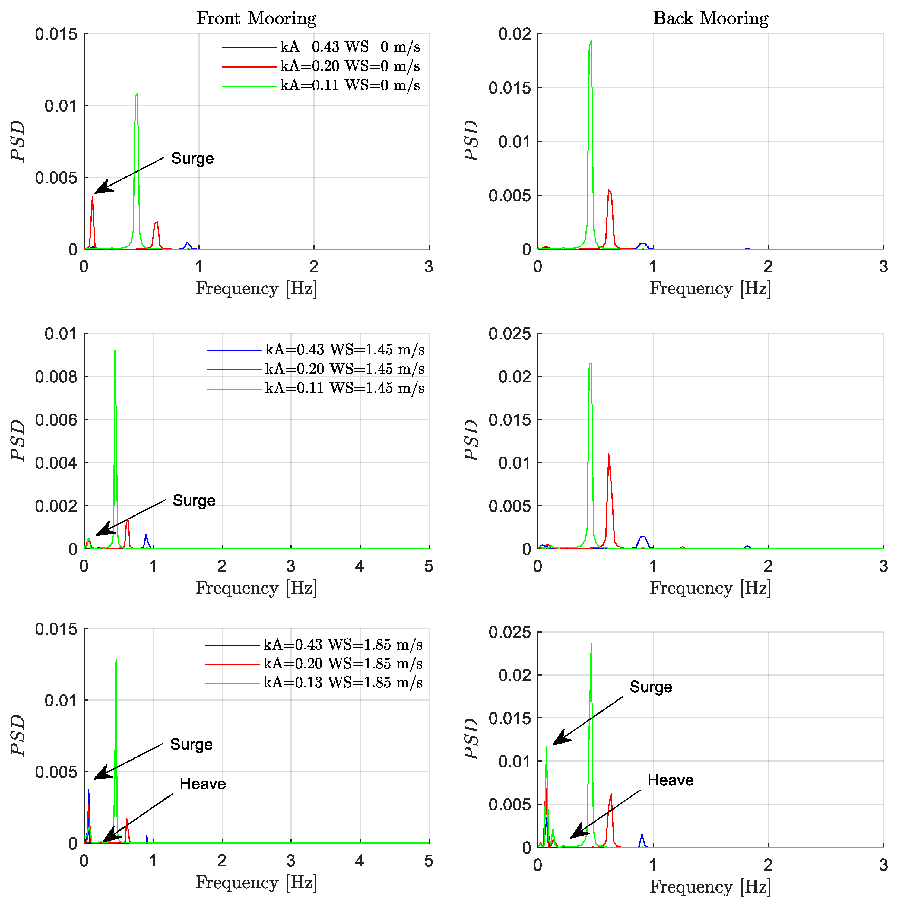
The presence of the mooring increases the natural frequency of the system in heave, roll and pitch of about 6, 3 and 10%, respectively. The majority of the tension in the mooring is related to the first harmonic of the waves. The power content is more pronounced in the back mooring for all the wind condition and for all the wave steepnesses. The surge natural frequency is identified to have nonlinear correlation with wind speed in the front mooring lines while, in the back mooring, it appears only in the above-rated condition.
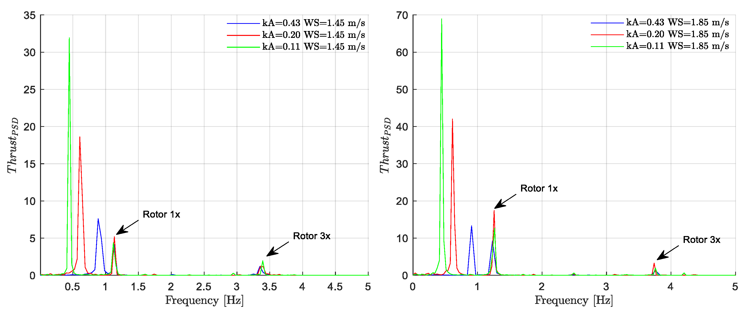
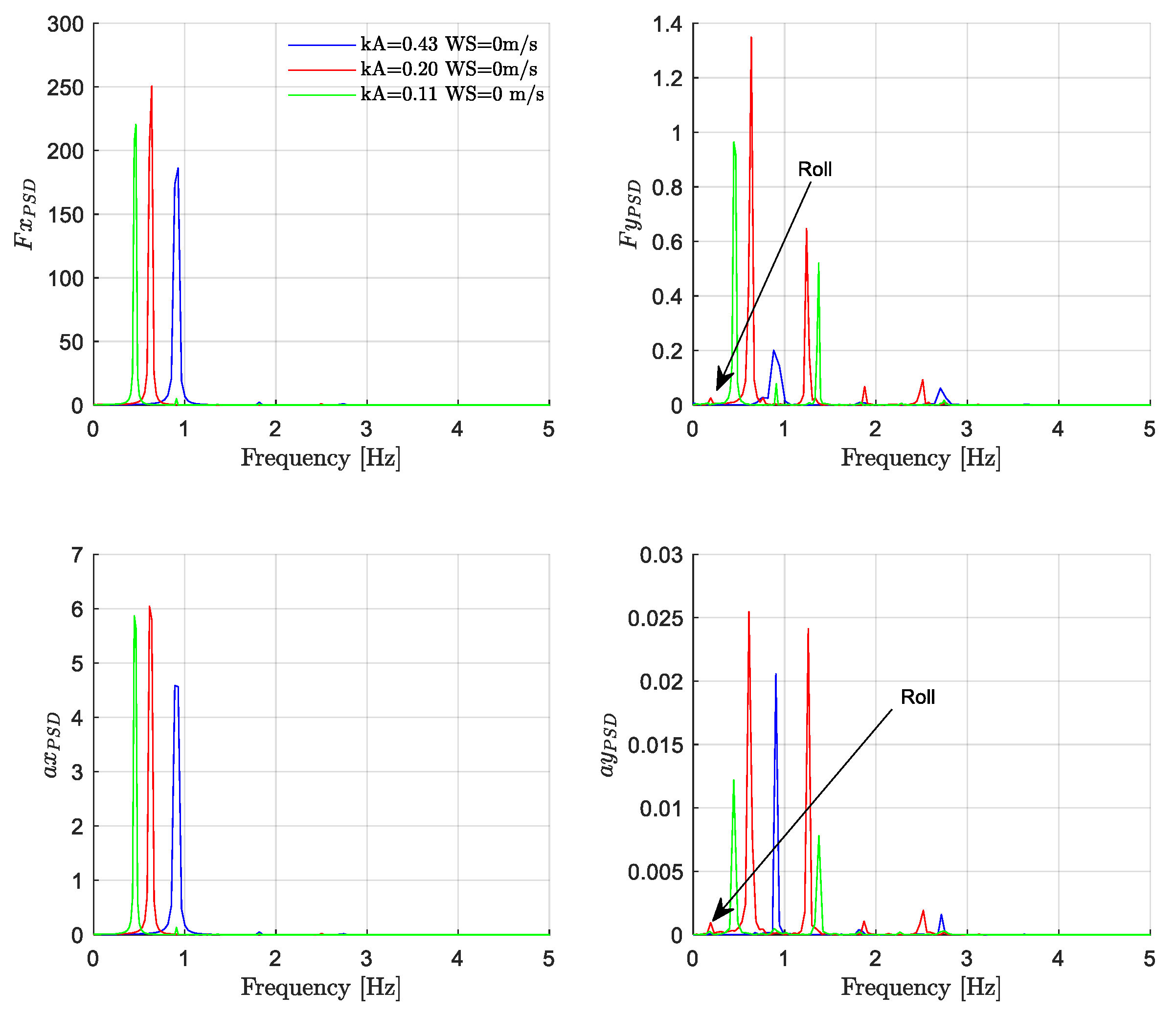
One of the most important result of the present work it is the assessment of the blade rotation role in several aspects. The rotor speed affects the dynamic of the overall structure being the thrust force, the forces and accelerations on the nacelle and the motion of the structure, excited by its harmonics. Concerning the thrust force, the increasing in the wind speed of about 27%, almost doubling the force along y-direction. Forces and accelerations on the nacelle instead, are excited at the first and third harmonic of the rotor speed in y-direction; however, in above-rated condition, also the second harmonic is excited.
The first three harmonics of rotor speed are clearly detected in the along y accelerations of the nacelle. However, the major contribution in terms of excitation is related to the first and third harmonics in below-rated condition, while becoming the power content associated to the second harmonic 1.5 times higher than the third harmonic in above-rated condition.
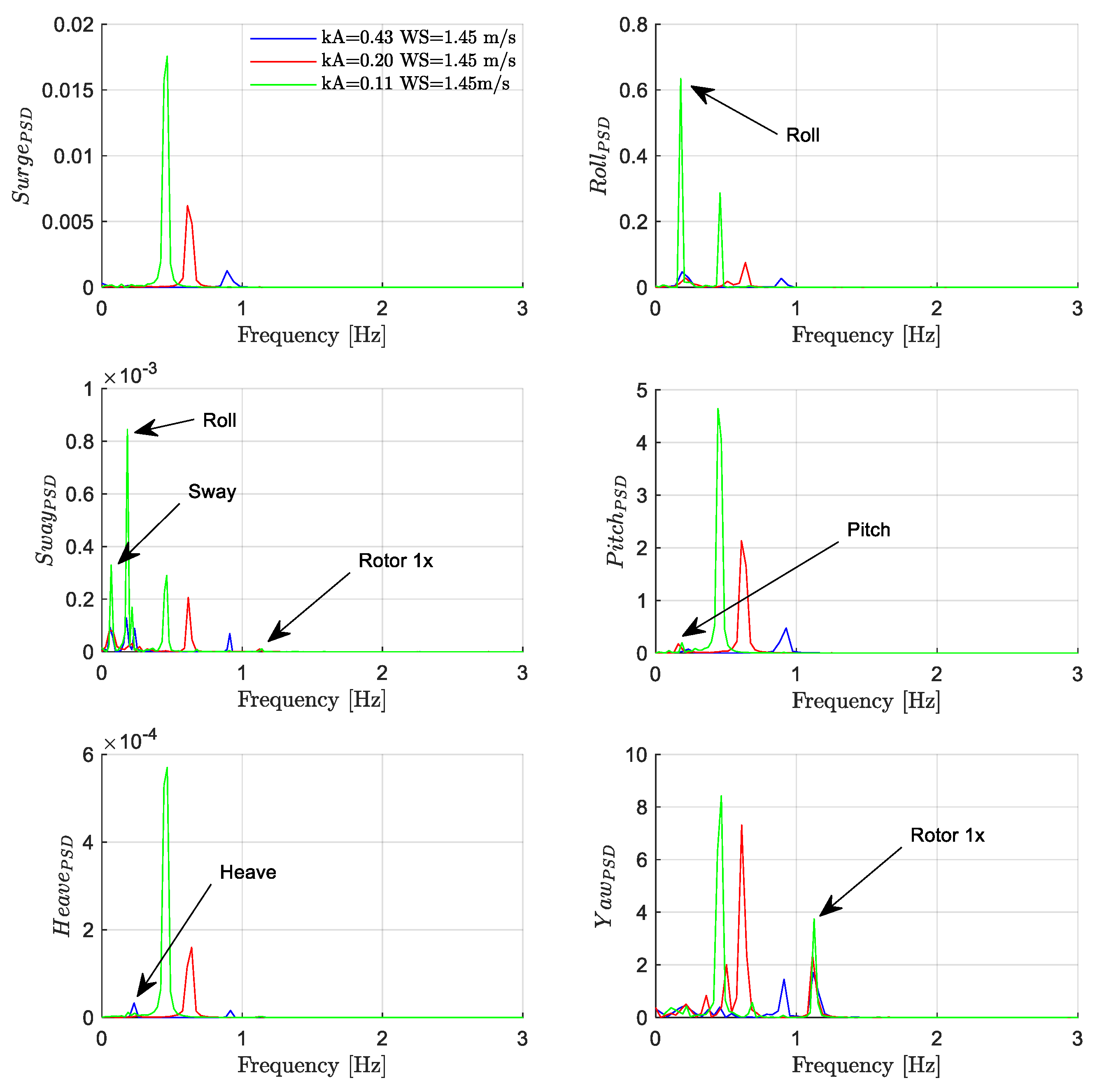
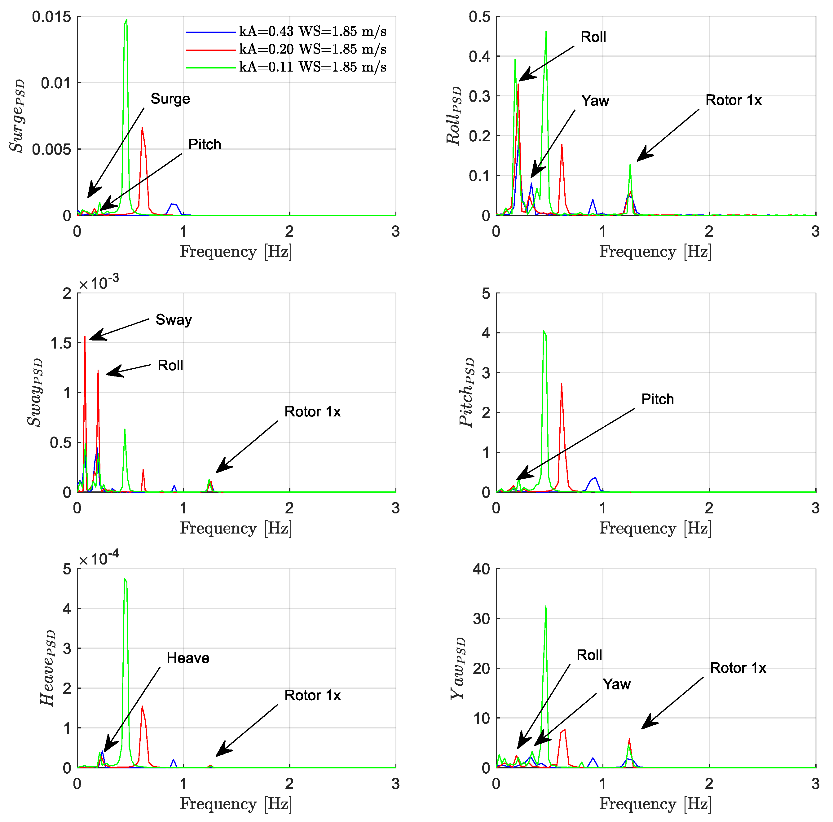
In addition, the three wave steepnesses presented a slight peak at the rotor frequency in sway and roll in below-rated condition; these peaks are detected also in above-rated condition where, they also occur in heave and roll.
What is surprising is that certain pairs of wind speed-wave steepness become particularly unfavorable, despite the wave energy content. In fact, in the above-rated condition, the energy content of the first rotor harmonic associated with the intermediate sea state is relatively higher than that in the lowest wave steepness (i.e., more energetic sea state). A heuristic explanation for this behavior should be attributable to the coupling between the first harmonics of the wave and the rotor, evidently promoting the generation of some nonlinear behavior.
The basically nontrivial feature of the described results is that the neglect of pitch-controlled, variable-speed blades within physical tests of a spar wind structure could lead to misleading results as to its dynamic behavior. For instance, the definition of extreme forces and fatigue stresses is complicated by a number of factors and motions of different time scales, and confusion can easily be generated when the rotor speed is empirically approximated.
The new dataset provided by this work might represents a comprehensive and controlled series of tests for evaluating and improve currently used numerical models.

Author Contributions

Conceptualization, S.R. and P.C.; methodology, S.R., E.L., A.B. and P.C.; software, S.R. and A.B.; validation, G.R.T., D.V. and G.I.; formal analysis, S.R., A.B. and P.C.; laboratory experiments, S.R., E.L.; data curation G.R.T., G.I., E.L. and D.V.; writing—original draft preparation, S.R.; writing—review and editing, S.R., A.B. and P.C.; supervision D.V., G.I. and G.R.T. All authors have read and agreed to the published version of the manuscript.

Funding

This research was funded by European Union in Horizon 2020 research and innovation program, under the grant No 654110, HYDRALAB+ (https://hydralab.eu/ (accessed on 17 June 2021)).

Data Availability Statement

The raw data analysed in this article are available online at: https://hydralab.eu/research--results/ta-projects/project/hydralab-plus/41/ (accessed on 17 June 2021).

Acknowledgments

For the original DHI tests, the authors would like record their appreciation for all the people involved: Marco Belloli, Federico Taruffi, Alessandro Fontanella, Simone Di Carlo, Sara Muggiasca (Polytechnic University of Milan), Claudio Lugni (INM-CNR),Antonio Francone (University of Salento), Luca Pustina (Roma Tre University), Vincenzo Ferrante (University of Campania “Luigi Vanvitelli”), Abel Martínez Díaz (University College Cork), John-Paul Latham, Lluis Via-Estrem, Jiansheng Xiang (University College London), Jaak Monbaliu, Griet Decorte (Catholic University of Leuven), Raùl Guanche Garcìa, Tommaso Battistella (University of Cantabria), Morten Thøtt Andersen, Jens Peter Kofoed, Morten Bech Kramer (Aalborg University), Axelle Vire, Irene Rivera-Arreba (Delft University of Technology). A special thanks is addressed to Bjarne Jensen, Björn Elsässer and the wider DHI team for design, construction, and support of testing.

Conflicts of Interest

The authors declare no conflict of interest.

References

  1. European Commission. European Strategic Energy Technology Plan. 2018. Available online: https://ec.europa.eu/energy/topics/technology-and-innovation/strategic-energy-technology-plan_en (accessed on 23 December 2020).
  2. European Commission. A European Green Deal: Striving to Be the First Climate-Neutral Continent. 2019. Available online: https://ec.europa.eu/info/strategy/priorities-2019-2024/european-green-deal_en (accessed on 22 January 2021).
  3. European Commission. An EU Strategy to Harness the Potential of Offshore Renewable Energy for a Climate Neutral Future. 2020. Available online: https://ec.europa.eu/energy/topics/renewable-energy/eu-strategy-offshore-renewable-energy_en (accessed on 30 January 2021).
  4. Wind Europe. Offshore Wind in Europe. Key Trends and Statistics 2019. Available online: https://windeurope.org/wp-content/uploads/files/about-wind/statistics/WindEurope-Annual-Offshore-Statistics-2019.pdf (accessed on 28 December 2020).
  5. Jeffrey, H.; Sedgwick, J. ORECCA European Offshore Renewable Energy Roadmap; University of Edinburgh: Edinburgh, UK, 2011. [Google Scholar]
  6. Borg, M.; Jensen, M.W.; Urquhart, S.; Andersen, M.T.; Thomsen, J.B.; Stiesdal, H. Technical definition of the tetraspar demonstrator floating wind turbine foundation. Energies 2020, 13, 4911. [Google Scholar] [CrossRef]
  7. Pantusa, D.; Francone, A.; Tomasicchio, G.R. Floating offshore renewable energy farms. A life-cycle cost analysis at Brindisi, Italy. Energies 2020, 13, 6150. [Google Scholar]
  8. Astariz, S.; Perez-Collazo, C.; Abanades, J.; Iglesias, G. Hybrid wave and offshore wind farms: A comparative case study of co-located layouts. Int. J. Mar. Energy 2016, 15, 2–16. [Google Scholar] [CrossRef] [Green Version]
  9. Perez-Collazo, C.; Greaves, D.; Iglesias, G. Hydrodynamic response of the WEC sub-system of a novel hybrid wind-wave energy converter. Energy Convers. Manag. 2018, 171, 307–325. [Google Scholar] [CrossRef]
  10. Wen, Y.; Kamranzad, B.; Lin, P. Assessment of long-term offshore wind energy potential in the south and southeast coasts of China based on a 55-year dataset. Energy 2021, 224, 120225. [Google Scholar] [CrossRef]
  11. Kamrazad, B.; Lavidas, G. Change of nearshore extreme wind and wave climate in Southeast Africa. In Proceedings of the SCACR19: 9th Short Course/Conference on Applied Coastal Research, Bari, Italy, 26 April 2019; EdiBios: Budesti, Romania, 2019; pp. 115–119. [Google Scholar]
  12. Uzunoglu, E.; Karmakar, D.; Soares, C.G. Floating offshore wind platforms. In Floating Offshore Wind Farms; Springer: Cham, Switzerland, 2016; pp. 53–76. [Google Scholar]
  13. Petersen, H. The scaling laws applied to wind turbine design. Wind Eng. 1984, 8, 99–108. [Google Scholar]
  14. Gasch, R.; Twele, J. Scaling wind turbines and rules of similarity. In Wind Power Plants; Springer: Berlin/Heidelberg, Germany, 2012; pp. 257–271. [Google Scholar]
  15. Canet, H.; Bortolotti, P.; Bottasso, C.L. On the scaling of wind turbine rotors. Wind Energy Sci. 2021, 6, 601–626. [Google Scholar] [CrossRef]
  16. Bayati, I.; Belloli, M.; Bernini, L.; Zasso, A. Aerodynamic design methodology for wind tunnel tests of wind turbine rotors. J. Wind Eng. Ind. Aerodyn. 2017, 167, 217–227. [Google Scholar] [CrossRef] [Green Version]
  17. Asl, M.E.; Niezrecki, C.; Sherwood, J.; Avitabile, P. Design of scaled-down composite I-beams for dynamic characterization in subcomponent testing of a wind turbine blade. In Shock & Vibration, Aircraft/Aerospace, Energy Harvesting, Acoustics & Optics; Springer: Cham, Switzerland, 2016; Volume 9, pp. 197–209. [Google Scholar]
  18. Bottasso, C.L.; Campagnolo, F.; Petrović, V. Wind tunnel testing of scaled wind turbine models: Beyond aerodynamics. J. Wind Eng. Ind. Aerodyn. 2014, 127, 11–28. [Google Scholar] [CrossRef]
  19. Stiesdal, H. Hywind: The world’s first floating MW-scale wind turbine. Wind Dir. 2009, 31, 52–53. [Google Scholar]
  20. Bento, N.; Fontes, M. Emergence of floating offshore wind energy: Technology and industry. Renewa. Sustain. Energy Rev. 2019, 99, 66–82. [Google Scholar] [CrossRef]
  21. Jonkman, J. Definition of the Floating System for Phase IV of OC3; No. NREL/TP-500-47535; National Renewable Energy Laboratory (NREL): Golden, CO, USA, 2010.
  22. Jonkman, J.; Larsen, T.; Hansen, A.; Nygaard, T.; Maus, K.; Karimirad, M.; Fylling, I. Offshore Code Comparison Collaboration within IEA Wind Task 23: Phase IV Results Regarding Floating Wind Turbine Modeling; National Renewable Energy Laboratory (NREL): Golden, CO, USA, 2010.
  23. Jonkman, J. Dynamics of offshore floating wind turbines-model development and verification. Wind Energy 2009, 12, 459–492. [Google Scholar] [CrossRef]
  24. Martin, H.R.; Kimball, R.W.; Viselli, A.M.; Goupee, A.J. Methodology for wind/wave basing testing of floating offshore wind Turbines. In Proceedings of the 31st International Conference on Ocean, Offshore and Arctic Engineering, Rio de Janeiro, Brazil, 10–15 June 2012. [Google Scholar]
  25. Koo, B.J.; Goupee, A.J.; Kimball, K.W.; Lambrakos, K.F. Model tests for a floating wind turbine on three different floaters. J. Offshore Mech. Arct. Eng. 2014, 136, 021904. [Google Scholar] [CrossRef]
  26. Jonkman, J.M.; Buhl, M.L., Jr. FAST User’s Guide; NREL/EL-500-38230 (Previously NREL/EL-500-29798); National Renewable Energy Laboratory: Golden, CO, USA, 2005.
  27. Nielsen, F.G.; Hanson, T.D.; Skaare, B. Integrated dynamic analysis of floating offshore wind turbine. In Proceedings of the International Conference on Ocean, Offshore and Arctic Engineering, Hamburg, Germany, 4–9 June 2006; ASME: New York, NY, USA, 2006. [Google Scholar]
  28. Skaare, B. Development of the Hywind concept. In Proceedings of the ASME 36th International Conference on Ocean, Offshore and Arctic Engineering, Trondheim, Norway, 25–30 June 2017. [Google Scholar]
  29. Utsunomiya, T.; Sato, T.; Matsukuma, H.; Yago, K. Experimental validation or motion of a SPAR-type floating offshore wind turbin using 1/22.5 scale model. In Proceedings of the ASME 28th International Conference on Ocean, Offshore and Arctic Engineering, Honolulu, HI, USA, 31 May–5 June 2009; pp. 951–959. [Google Scholar]
  30. Myhr, A.; Maus, K.J.; Nygaard, T.A. Experimental and computational comparisons of the OC3-Hywind and tension-leg-buoy (TLB) floating wind turbine conceptual designs. In Proceedings of the International Society of Offshore and Polar Engineering Conference, Hawaii, HI, USA, 19–24 June 2011. [Google Scholar]
  31. Sethuraman, L.; Venugopal, V. Hydrodynamic response of a stepped-spar floating wind turbine: Numerical modeling and tank testing. Renew. Energy 2013, 52, 160–174. [Google Scholar] [CrossRef]
  32. Nallayarasu, S.; Saravanapriya, S. Experimental and numerical investigation on hydrodynamic response of spar with wind turbine under regular waves (Part I). Int. J. Ocean Clim. Syst. 2013, 4, 239–260. [Google Scholar] [CrossRef] [Green Version]
  33. Nallayarasu, S.; Saravanapriya, S. Experimental and numerical investigation on hydrodynamic response of spar with wind turbine under random waves (Part II). Int. J. Ocean Clim. Syst. 2013, 3, 261–282. [Google Scholar] [CrossRef]
  34. Goupee, A.J.; Koo, B.J.; Kimball, R.W.; Lambrakos, K.F.; Dagher, H.J. Experimental comparison of three floating wind turbine concepts. J. Offshore Mech. Arct. Eng. 2014, 136, 020906. [Google Scholar] [CrossRef]
  35. Duan, F.; Hu, Z.; Niedzwecki, J.M. Model test investigation of a spar floating wind turbine. Mar. Struct. 2016, 49, 76–96. [Google Scholar] [CrossRef] [Green Version]
  36. Shin, H. Model test of the OC3-Hywind floating offshore wind turbine. In Proceedings of the 21st ISOPE, Maui, HI, USA, 19–24 June 2011. [Google Scholar]
  37. Ahn, H.J.; Shin, H. Model test and numerical simulation of OC3 spar type floating offshore wind turbine. Int. J. Nav. Archit. Ocean Eng. 2019, 11, 1–10. [Google Scholar] [CrossRef]
  38. Tomasicchio, G.R.; D’alessandro, F.; Avossa, A.M.; Riefolo, L.; Musci, E.; Ricciardelli, F.; Vicinanza, D. Experimental modelling of the dynamic behaviour of a spar buoy wind turbine. Renew. Energy 2018, 127, 412–432. [Google Scholar] [CrossRef]
  39. Tomasicchio, G.R.; Avossa, A.M.; Riefolo, L.; Ricciardelli, F.; Musci, E.; D’Alessandro, F.; Vicinanza, D. Dynamic modelling of a spar buoy wind turbine. In Proceedings of the 36th International Conference on Ocean, Offshore and Arctic Engineering, Trondheim, Norway, 25–30 June 2017; ASME: New York, NY, USA, 2017. [Google Scholar]
  40. Ruzzo, C.; Fiamma, V.; Nava, V.; Collu, M.; Failla, G.; Arena, F. Progress on the experimental set-up for the testing of a floating offshore wind turbine scaled model in a field site. Wind Eng. 2016, 40, 455–467. [Google Scholar] [CrossRef] [Green Version]
  41. Tomasicchio, G.R.; Vicinanza, D.; Belloli, M.; Lugli, C.; Latham, J.; Jensen, B.; Vire, A.; Monbaliu, J.; Taruffi, F.; Pustina, L.; et al. Physical model tests on spar buoy for offshore floating wind energy conversion. Ital. J. Eng. Geol. Environ. 2020, 1, 129–143. [Google Scholar] [CrossRef]
  42. Mansard, E.P.D.; Funke, E.R. The measurement of incident and reflected spectra using a least squares method. Coast. Eng. 1980, 1980, 154–172. [Google Scholar]
  43. Jonkman, J.; Butterfield, S.; Musial, W.; Scott, G. Definition of a 5-MW Reference Wind Turbine for Offshore System Development; No. NREL/TP-500-38060; National Renewable Energy Laboratory (NREL): Golden, CO, USA, 2009.
  44. Lifes50+. Deliverable 3.1. Available online: http://lifes50plus.eu/results/ (accessed on 3 March 2021).
  45. Bak, C. The DTU 10-MW Reference Wind Turbine; Technical University of Denmark, DTU Wind Energy: Copenhagen, Denmark, 2013. [Google Scholar]
  46. DNVGL. DNV-OS-E301. 2015. Position Mooring. Available online: https://rules.dnv.com/docs/pdf/DNV/os/2015-07/DNVGL-OS-E301.pdf (accessed on 15 July 2020).
  47. DNVGL. DNVGL-ST-0119.2018. Floating Wind Turbine Structures. Available online: https://rules.dnv.com/docs/pdf/DNV/ST/2018-07/DNVGL-ST-0119.pdf (accessed on 9 June 2020).
Figure 1. (a) Test facility during a test (b) tower and rotor–nacelle-assembly instruments.
Energies 14 03598 g001
Figure 2. (a) Plan view of the instruments around the structure. (b) Sketch of the inertial platforms and mono-axials accelerometers distribution during tests.
Energies 14 03598 g002
Figure 3. (a) Wind turbine set-up and (b) only wind.
Energies 14 03598 g003
Figure 4. Response of the wind turbine to free decay tests in time and frequency domain along the x direction (top) and y direction (bottom).
Energies 14 03598 g004
Figure 5. PSD of thrust forces in below (left) and above (right) rated conditions.
Energies 14 03598 g005
Figure 6. PSDs of motion, WS = 0 m/s.
Energies 14 03598 g006
Figure 7. PSDs of motion, WS = 1.45 m/s.
Energies 14 03598 g007
Figure 8. PSDs of motion, WS = 1.85 m/s.
Energies 14 03598 g008
Figure 9. Dynamic forces and accelerations on the nacelle in no-wind condition: on the left side, in the x-direction, on the right side, in the y-direction.
Energies 14 03598 g009
Figure 10. Dynamic forces and accelerations on the nacelle in the below-rated condition.
Energies 14 03598 g010
Figure 11. Dynamic forces and accelerations on the nacelle in above-rated condition.
Energies 14 03598 g011
Figure 12. PSDs of mooring lines tension response, front and back respectively in left and right column. Top to bottom: no wind condition, below-rated condition, above-rated condition.
Energies 14 03598 g012
Table 1. Wind turbine properties.
Wind Turbine PropertiesModel ScaleFactor (*)Full Scale
Rotor orientationClockwise, Upwind
ControlVariable speed, Collective Pitch
Number of blades3-3
Rotor diameter [m]3.15λ126
Hub diameter [m]0.075λ3
Tower diameter [m]0.08λ3.2
Elevation to tower base above SWL [m]0.25λ10
Elevation to tower top above SWL [m]2.19λ87.6
Single blade mass [kg]0.21λ313,440
Hub height [m]2.25λ90
Rotor mass [kg]1.72λ3110,000
Nacelle mass [kg]3.75λ3240,000
Cut-in, rated, cut-out wind speed [m/s]0.5–1.8–4λ1/23–11.4–25
Cut-in, rated rotor speed [rpm]43.7–76.5λ−1/26.9–12.1
Ideal power [W]12.35λ7/25.00 × 106
Gearbox ratio42-97
(*) In this table and in the following the term, “Factor” indicates the scale factor, according to Froude similarity rule, for which the model scale values need to be multiplied in order to obtain the full-scale quantities. In particular, λ = 40.
Table 2. Platform properties.
Spar Buoy PropertiesModel ScaleFactorFull Scale
Diameter, upper and lower cylinders [m]0.163–0.235λ6.5–9.4
Total draft [m]3λ120
Depth to top of taper below SWL [m]0.1λ4
Depth to bottom of taper below SWL [m]0.3λ12
Center of gravity below SWL [m]2.25λ90
Mass, including ballast [kg]116.66λ37,466,240
Roll and pitch inertia [kg·m2]41.30λ54.23 × 10⁹
Yaw inertia [kg·m2]1.60λ51.64 × 10⁸
Table 3. Mooring system properties.
Mooring Lines PropertiesModel ScaleFactorFull Scale
Number of mooring lines3
Horizontal angle between adjacent lines [°]120
Vertical angle between floater and lines [°]32.6
Depth to anchors below SWL [m]3λ120
Depth to fairleads below SWL [m]1.75λ70
Radius to anchors from platform centerline [m]2.05λ82
Spring pretension [kg]1.5λ396,000
Unstretched spring length [m]1.21λ48.4
Stretched spring length [m]1.75λ70
Equivalent springs extensional stiffness [N/m]27.25λ243,600
Stretched mooring line length [m]2.25λ90
Table 4. Decay tests.
DoFMoored PlatformWS [m/s]
Heave
RollNo0
Pitch
Surge 0 1.25 1.45 1.65 1.85 1.95
SwayYes0
Heave 0 1.25 1.45 1.65 1.85 1.95
Roll 0
PitchYes0 1.25 1.45 1.65 1.85 1.95
Yaw 0 1.25 1.45 1.65 1.85 1.95
Table 5. Wind turbine natural frequency identification.
ConfigurationForce PositionDirection
Wind TurbineIdentificationTower Topx-y
Table 6. Analyzed tests.
H [m]T [s]kA [–]WS [m/s]DD [°]Test Type
0.131.10.43 0Regular
No wind
1.60.200
2.20.11
1.10.43 0Regular
Below rated
1.60.201.45
2.20.11
1.10.43 0Regular
Above rated
1.60.201.85
2.20.11
Table 7. Wind turbine natural frequency identification.
DirectionTm [s]fn [Hz]StdTm [s]
x0.4682.1360.003
y0.4532.2090.004
Table 8. Mooring influence on natural frequency.
DoFfn [Hz]Δfn [%]
fn,unmooredfn, moored
Heave0.2100.2235.83
Roll0.1790.1853.24
Pitch0.1890.21010.00
Table 9. Wind influence on natural frequency.
Natural Frequency fn [Hz]
Wind Speed [m/s]SurgeSwayHeaveRollPitchYaw
00.0850.0670.2230.1850.2100.397
1.250.079/0.225/0.183(*)
1.450.078/0.226/0.183
1.650.077/0.227/0.183
1.850.077/0.227/0.183
1.950.077/0.228/0.183
(*) No natural frequency was derived from decay tests with wind in yaw DoF. Its presence highlighted the inability of the structure to oscillate because kept in position by the wind force.
Table 10. First, second and third harmonic frequencies of the waves.
kA (–)Frequency 1x (Hz)Frequency 2x (Hz)Frequency 3x (Hz)
0.430.9091.8182.727
0.200.6251.251.875
0.110.4540.9091.363
Table 11. Rotor frequencies.
Wind Speed (m/s)Rotor Frequency 1x (Hz)Rotor Frequency 3x (Hz)
1.451.123.39
1.851.253.75
Publisher’s Note: MDPI stays neutral with regard to jurisdictional claims in published maps and institutional affiliations.

