1. Introduction
Nowadays, environmental issues are a worldwide concern. States and companies aim at limiting their environmental impact by reducing their fossil energy consumption and pollution. This meets customers’ demand for greener products while being an advantage from an economical point of view considering the continuously rising taxation on gas.
The process of spirit production currently used in the industry guarantees the taste and the quality of the product, nevertheless it is not satisfyingly enough optimized from an energetical point of view. The distillation process is based on two energy sources: Gas accounts for 95% and electricity for only 5%. A large quantity of water is also used in the process. For the pot still considered in this study, around 1.5 m3 of water distillation is used for each distillation cycle and a part is released into the atmosphere as the top water layer of the water condensing tank evaporates.
The brandy considered in the study is a spirit at 70%
v/
v of ethanol, obtained by a white wine double distillation in a gas-powered copper pot still. It differs from other types of brandy, rum or vodka, which are generally distilled continuously. The low wine is the condensate subsequent to a wine distillation. The pot still used is described in
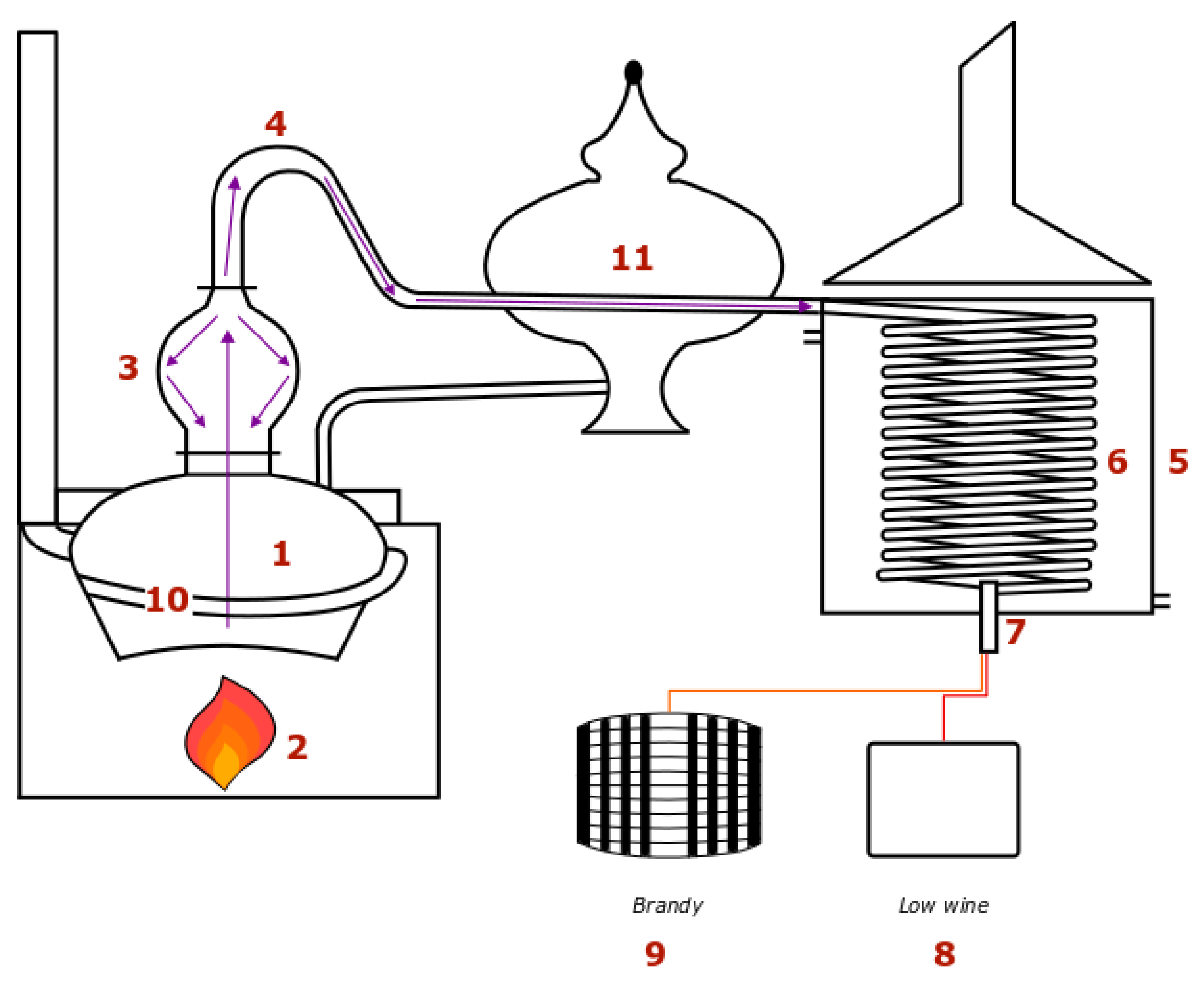
Figure 1.
The distillation apparatus is composed of a boiler (1) in which the liquid is heated up by an open flame (2). Components evaporate and go up through the still head (3), then the swan neck (4) before reaching the condenser (5) which is an open system. Part of the vapor condensates on the walls of the still head and flows down back into the boiler. The vapors subsequently obtained are thus richer in ethanol. The condenser is an open system. It is a tank filled with cold water in which a coil (6) is immerged. Vapors inside the coil condense and cool down. The distillate runs down the coil and goes through an alcoholmeter (7) when coming out. It is separated into different fractions. Some are recycled in the wine or in the low wine (8) reception tank, the rest is the brandy, which is put into barrels for ageing (9). Separation of the different fractions is carried out by tasting. This delicate operation has an impact on the quality of the product. As far as the condenser is considered, most of the time, the water in the tank is stagnant. When the distillate temperature gets too high, cold water is added through a valve at the bottom of the tank, while hot water in excess is discharged at the top. It is cooled in a refrigeration unit to be used in the tank again. Refrigerating hot water consumes electricity.
Finally, it is important to note that energy saving and revalorization systems already exist on copper pot stills. A first system consists of preheating the wine prior to distillation using the vapor heat of the preceding distillation. The wine preheater (11) is set between the swan neck and the condenser. It is crossed by the pipe in which the hot distillate vapor flows. This enables heating up the wine before transferring it into the boiler. Some distillers use a multitubular or a plate exchanger instead. The wine is directly taken from a tank and heated up while it goes through the exchanger. It then goes into the boiler or is held aside in a storage tank. For these two systems, the calorific fluid is the hot water of the condenser tank. Its temperature is between 70 and 80 °C and the volume available is largely sufficient to preheat the wine from around 12 °C up to the required temperature. Essential aromatic compounds are extremely volatile, they vaporize at low temperatures, so usually the wine is not preheated above 35–40 °C to avoid degradation of the flavor. The low wine is not preheated at all for flavor reasons, as well. Another system is the smoke exchanger (10). It is a pipe encircling the lower part of the boiler so as to remain below the liquid level even when it is at its lowest at the end of the distillation. Thus, the combustion fumes flowing through the pipe give some of their energy to the liquid in the boiler.
Thermal efficiency of alcohol distillations has been largely studied for continuous regime and for column distillation apparatus [
1,
2,
3,
4,
5,
6]. Batch distillation of wine to produce Cachaça or Pisco, for instance, has also been studied, though essentially from a chemical point of view [
1,
7,
8,
9,
10,
11,
12]. However, only few thermal studies have been led on a wine batch distillation in a gas-heated copper pot still.
As previously mentioned, a large number of chemical models have been tested to describe the liquid-vapor equilibrium taking into account other components of the water-ethanol mixture. Equilibrium conditions are essential to simulate batch distillations insofar as the force flow, which separates the components and is correlated to the varying concentrations. In the wine, there is a multiplicity of secondary components, whose concentration varies between 10
−4 and 10
−6 mg/L [
10,
11]. Models only consider 6 to 8 components in addition to water and ethanol. The components depend on the distillate which is produced. Fundamental equations of mass and energy are resolved using fugacity expressions to describe the liquid-vapor equilibrium, as well as vapor composition. Raoult and Antoine laws can also be used to understand the theorical composition and the vapor pressure [
8]. These models are complex but accurate, hence ideal for a chemical analysis. Nevertheless, they are unnecessarily elaborate for a thermal study even if the values of the ethanol-water liquid-vapor equilibrium is required.
Batch distillation processes are difficult to optimize since they do not just come down to a plate number or a reflux problem as they do, for instance, for column distillations, which can be optimized by algorithms [
13]. Nonetheless, few articles deal with thermal fluxes in batch distillations. Two strategies can be found in the literature. The system can be enhanced either by modifying the process or via automation.
Scanavini et al. have considered a copper pot still and studied the losses by natural convection for a wine batch distillation [
14]. The experimental pot still is loaded with 0.008 m
3 of wine and heated by an open flame. A natural reflux occurs at the level of the swan neck walls. The pot still is shown in
Figure 2. It must be noticed that its shape slightly differs from the shape of the pot still considered in the present study. To resolve energy balances, the liquid-vapor equilibrium along the swan neck is modelled. Partial vapor pressions, activity factors, and binary interaction parameters are respectively determined by empirical equations, an NRTL model, and Aspen Plus software database. Thermal losses by natural convection are calculated. To determine the exchange surface, the system is discretized into a rectangle, a semi-sphere, and two vertical cylinders. Results show that the losses by natural convection are insignificant and can be neglected. However, it must be reminded that the considered pot still is a small size.
Cavaletto has led experiments on a micro-scale pot still to study thermal efficiency [
15]. Numerous factors such as the burner efficiency, radiant heat losses, and energy losses of the cooling water are not considered. The pot still is fitted with a metal jacket which enables reducing energy needs by 31% and distillation duration by 32%. It finally improves the overall efficiency of the system by 13%. To conclude, insulating of the boiler proves to be of great importance.
Distillers’ concern for gas consumption and heat waste dates back from a long time [
16,
17]. Two different experiments were led by Lafon et al. [
17] in 1973. The first one is an attempt to produce brandy by continuous distillation in a plate column. Even if a continuous process requires less energy and is more efficient, it evinces drawbacks when applied to brandy distillation. First, the impurities are not properly separated from the rest of the distillate due to the reflux. Second, as the wine only stays from 10 to 15 min in the column, some components in particular some esters and essential oils are not produced [
16]. Third, copper is a catalyst for a number of chemical reactions which will not occur here since there is generally no copper in a plate column. Then, the plates get fouled up which gives an inappropriate flavor to the brandy. Finally, the speed of the distillation is more difficult to control. This is a major drawback since control upon the different fractions is critical. Therefore, modifiying the system to reduce energy consumption has to be thoroughly considered as the quality of the spirit can be affected.
The energy source has changed over years. At one time, coal was employed. In a second experiment, a thermal analysis of the influence of wine preheating on coal consumption is conducted with a wine at 15 °C [
17]. The wine is preheated up to 45 °C in the wine preheater, 11% of energy is saved. Then, another test is carried out. The wine is preheated to 65 °C which enables gaining 18% of energy. However, the flavor of the final product is not evoked.
An idea to diminish energy consumption and to improve efficiency is to replace the current system by a column pot still, for instance. García-Llobodanin et al. have compared reproducibility and product composition in the case of a pear spirit first obtained when performing a double distillation with a traditional copper pot still and then a batch distillation in a stainless-steel boiler topped with a copper rectifying column [
7]. Results show that the first system is the most repeatable, the composition of the two spirits is radically different, and column distillation allows extracting more ethanol. These conclusions echo Lafon et al. [
16] and confirm that upgrading the distillation process can affect the quality of the spirit.
Industrials also care about energy consumption, therefore they often decide in favor of automation. The main advantage is convenience, then it enables optimizing the efficiency to a certain extent. Automation aims at producing the largest possible quantity of brandy free from any contamination by other distillate fractions [
18]. Boucher et al. and Saco et al. have tried to monitor effectors automatically [
18,
19].
A system is developed to control a wine copper pot still whose heat source is steam and which includes a rectifier [
18]. The monitored parameters are the output valves of the rectifier, the condenser, the storage tanks receiving the different distillate fractions, and the vapor feed. It is concluded that the system thermal efficiency and the flavor of the product are improved.
A similar system has been tested by industrials in partnership with Gaz de France and Supélec [
19]. The varying parameters that are adjusted are the temperature and the flow rate of the distillate, hence the gas pressure and the water flow rate of the cooling system are controlled in real-time. This system enables saving more than 20% of energy. The impact on the flavor is not evoked.
In a patent, Pruhlo describes a monitoring system to be set on a brandy pot still [
20]. It includes controlled inputs by Boucher et al. [
19]. Pruhlo adds controls on the chimney damper and on the distillate tanks to separate the different fractions. A vapor temperature sensor is set at the output of the still head. The temperature is correlated to the ethanol fraction of the distillate. The collected data enable selecting the appropriate reception tank, controlling the opening of the water valve, and adjusting the gas power. Additional sensors are also set in the chimney to measure CO, CO
2, and O
2 quantities in order to determine the appropriate opening for the damper.
Potential energy saving solutions have been studied by Newbert [
3]. A system based on automatic monitoring has been tested on whisky pot stills at Bell’s Dufftown Distillery, with vapor as energy source. The steam supply is automatically stopped when the value of the alcohol produced equals the cost of the steam required to produce it.
Automation is often used in industrial distilleries as previously mentioned [
2,
18,
19,
20]. Nevertheless, as far as brandy is concerned, the distillate fractions are traditionally separated by tasting. Partial automation is often implemented but the energy gain is limited. None of the studies quoted consider the flavor of the brandy, while it is a prime constraint. Apart from natural convection on walls which proves minor, energy fluxes in a copper pot still have never been accurately studied [
14,
15]. No transient thermal analysis has ever been led, although it is specific to batch distillation, therefore the present study focuses on how parameters and energy fluxes evolve with time. Moreover, even if revalorization systems have largely been studied for continuous and column batch distillations, none exist for traditional pot stills.
The present study focuses of the heating part of a copper pot still since it is the main site of energy expenditures. The first objective is to achieve a thermal diagnosis of the system to identify and quantify the major sites of energy losses, energy consumption, and potential recovery. The study is led in transient regime to determine the evolution of energy fluxes during distillation and to find out when the process is most efficient. The nodal method is used to solve mass and energy balances. Finally, prospective enhancements of the process are suggested.
2. Materials and Methods
A measurement campaign has been led over 3 months on an industrial scale pot still instrumented in order to calculate energy balances. The system studied is composed of the combustion chamber, the boiler, the smoke exchanger, the ground, and the boiler insulating shell.
The boiler is loaded with 1.2 m
3 of wine at 35 °C or low wine around 15 °C. It is heated by a natural gas flame. Insulation around the boiler is ensured by an octagonal stainless-steel shell lined up with glass wool. When the boiling point is reached, part of the vapor goes up through the still head then along the swan neck, while the rest condensates on the walls which produces a natural reflux. The flow rate and the composition of the vapor evolve over time, while the mixture inside the boiler gets ethanol-depleted. Instrumentation is detailed in
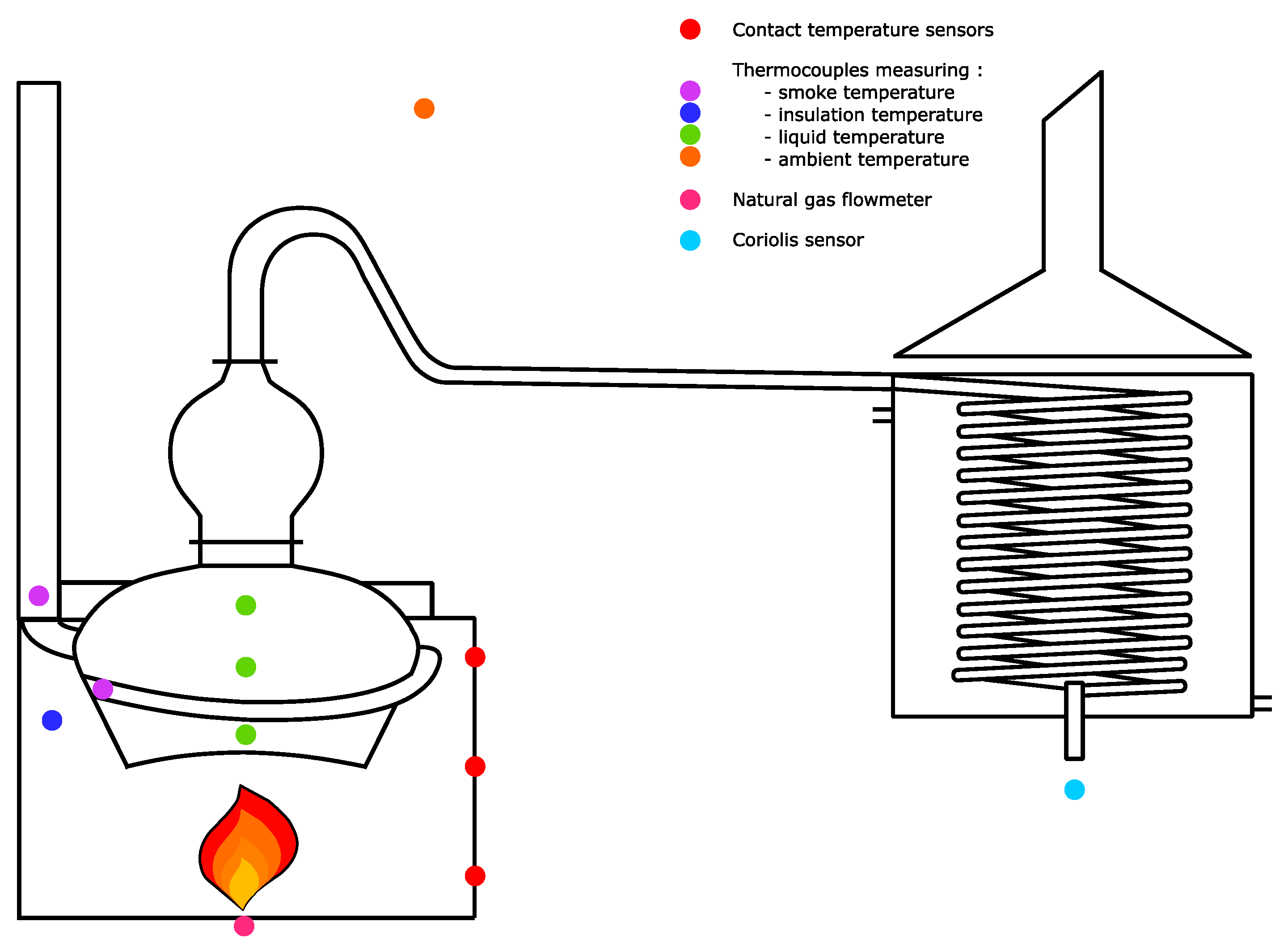
Figure 3.
A SLA5800 series volumetric flow sensor (Serv’ Instrumentation) is set at the entry of the burner to measure the gas flow rate. Its accuracy varies between and . Two types of burners can be used, the main difference between them is the oxidizer feed. As far as forced-draft burners are concerned, a fan forces the air into the burner. These burners are usually chosen since they are more efficient and easier to control. However, a forced-draft burner would be too powerful considering the small scale of the present setup. Therefore, an atmospheric burner is set, even if the excess of air is less finely adjusted. The pot still is also fitted with PT100 thermocouples (Corema). Their accuracy depends on the temperature, it varies between 0.3 and 0.8 °C. Two thermocouples measure the smoke temperature at the input and output of the smoke exchanger. Another one measures the temperature in the insulating layer, a fourth one the ambient air temperature, and the last three ones record the temperature of the liquid at various heights inside the boiler. These three thermocouples allow checking the homogeneity of the liquid temperature. In fact, it proves to be homogeneous which can be explained by convection movements. Three outer faces of the insulating shell are fitted with nine PT100 temperature contact sensors (Prosensor) at different heights. The volumetric flow rate of the distillate is measured at the output of the tank by a Proline Promass E100 Coriolis sensor (Endress + Hauser), whose accuracy is . It measures the temperature, the mass density, the flow rate, and the ethanol fraction. Measurements are taken every 20 s, which is a very short time step considering the precision of the different sensors. Data are smoothed for 1 min to reduce the noise while keeping an acceptable precision. The time step is thus kept short enough. Moreover, as the physical parameters change slowly, the regime can be considered as quasi-stationary during a time step.
The system model is based on the nodal method in order to define a system of equations of mass and energy balances. This is a numerical method, which discretizes the studied system into several nodes. Each node is described by its heat capacity, thermal power, and temperature [
21]. The mean value of these parameters is considered [
22]. This method is often used to simulate thermal fluxes in buildings or study complex geometries. Discretization and resolution methods already exist for distillation systems but no thermal model has been found in literature for a traditional batch distillation apparatus. Tools such as Aspen Plus or Prosim allow simulating batch distillations but the objective of the present study is to develop a model for a thermal diagnosis [
1]. The present experimental setup can easily be discretized into several nodes and the equation system is resolvable numerically.
Heat transfers between nodes are assessed by the nodal model and Kirchoff law is applied [
23]. The thermal conductance G
ij is used to describe connections between nodes i and j. The heat exchange between these two nodes is thus written:
A specific study is required to determine the different conductances. They depend on the type of transfer, the shape of the node, and the temperature [
24]. The convection, conduction, and radiation transfer conductances of the experimental setup are calculated. The conductive thermal conductance highly depends on the geometry of the control elements. Planar and cylindrical geometries are mainly used. Their parameters are presented in
Figure 4. and their respective formulae [
24] are:
and
The distance between the nodes and conductivity of the materials always impact the heat transfer. In the present case, the planar element conductance is used.
The thermal conductance for a convection transfer is:
A lot of empirical equations exist to describe the convection coefficient in function of the geometry, the type of medium, the flow regime, and the temperature range. In the present setup, there are only natural convection movements. Therefore, the convection coefficient ranges from 5 to 10 W/m2/K.
Thermal radiation transfers are generally negligible. This assumption has to be validated, so the conductance is calculated. Conductance of the heat lost by radiation from a grey surface to ambient air in a transparent medium without multiple reflection [
22] is described in Equation (5):
Simultaneously, the internal energy variation and mass balances have to be calculated. Software such as ESATAN or GAETAN allow a numerical resolution by the nodal method. Nevertheless, MATLAB can also be used [
24].
The system is discretized into nodes as required by the nodal method. It is composed of the boiler, the smoke exchanger, the ground, and the insulating shell. These four nodes interact as shown in
Figure 5 and
Figure 6.
The first node is the boiler plus its load of liquid. The energy is received from the combustion chamber and the exchanger is used to heat the water-ethanol mixture and vaporize the distillate .
The second node is the smoke exchanger. The energy entering this node comes from gas combustion and is partially transferred to the boiler while the rest is lost into the chimney .
The third node is the ground underneath the fireplace. As there is no insulation, part of the combustion chamber heat is lost by conduction .
The last node is the glass wool-lined shell around the boiler and the exchanger. It stores part of the energy supplied by the boiler , combustion chamber, and especially by the smoke. There are also losses by natural convection and radiation on the shell walls.
The boundary condition of the system is defined by the energy source . Initial conditions are the temperature, ethanol mass fraction, and volume of the wine, which are respectively 1174 kg, 35 °C and 0.078 kg/kg for the distillation presented here.
The thermal diagnosis is realized thanks to the experimental data and energy balance equations. As the process is a batch distillation, the regime is transient and all equations have to be written in function of time. Temperatures, flow rates, and distillate composition are provided by the sensors. Thermophysical parameters are calculated by correlations taken from scientific literature. Regarding recorded data values, approximations are made to simplify energy balance equations. Hypotheses are also made to simplify calculations.
Concerning the boiler node, the wine and low wine are considered as a water-ethanol mixture. From a thermal perspective, the other components can be neglected as they are in low concentrations. Indeed, the second most important secondary component reaches a maximal concentration value of 2 mg/m
3 only, which is extremely low compared to ethanol and water quantities [
11].
A distillation can be divided into two phases. During phase 1, the liquid is heated to a boiling temperature. During phase 2, it vaporizes and gets ethanol-depleted (cf.
Figure 7). Consequently, the boiling temperature continues to increase though more slowly. The liquid and vapor phases are considered to be at thermodynamic equilibrium. Hence, ethanol fractions for a given temperature are determined with the equilibrium diagram. It must be reminded that thermophysical parameters vary with the temperature and also depend on the composition of the fluid considered (cf.
Appendix A).
The natural reflux is difficult to assess with accuracy. It depends on the ambient temperature and the composition of the vapor. The condensing temperature of water is higher than that of ethanol. Therefore, there is proportionally less ethanol in the reflux than in the distillate, which gets enriched in ethanol. For more convenience, the reflux rate is empirically set at 5% and it is considered that only water condenses.
As far as gas combustion is concerned, different samples of the natural gas used are analyzed by gas chromatography for 1 month. The mean composition, is deduced (see
Table 1). Considering the gas as perfect allows determining its lower caloric value (PCI) based on the PCI of each component, which equals 37.5 MJ/Nm
3.
The injected gas flow rate varies according to the following parameters:
Flow rate curves are not the same for night and day-time distillations. Night distillations are shorter for practical reasons.
The gas flow rate also varies in function of time. An example of a standard curve for a wine distillation is presented in
Figure 8. The gas flow rate reaches a peak (0.038 Nm
3/min) during the first phase of the distillation and then at the beginning of phase 2, it gradually decreases down to a minimum value of 0.012 Nm
3/min. As for the flow rate of the low wine, it first equals 0.024 Nm
3/min before increasing to 0.0245 Nm
3/min.
Finally, the gas flow rate has to be adjusted to the initial ethanol concentration of the wine or that of the low wine. It has to be higher when there is more alcohol to extract in order to keep the distillation duration constant.
The composition and quantity of the combustion smoke are determined with the characteristics of the natural gas and combustion Equation (6) [
25]:
It is assumed that the combustion air is composed of 79%
v/v dinitrogen and 21%
v/v dioxygen. As carbon monoxide is dangerous for human health, it is essential to adjust the atmospheric burner so that it does not produce any, which means the combustion has to be complete. Therefore, the oxidizer, i.e., dioxygen, has to be in excess that is to say above the stoichiometric quantity. For similar burners excess air λ
air is difficult to adjust, so the air factor varies. It is measured with an ECOM J2KN PRO gas analyzer for different gas flow rates. Statements are taken when no distillation is in progress, i.e., with only hot water in the boiler. Results show that the air factor varies from 1.47 to 1.58, which is relatively close. Indeed, the burner and the chimney damper are set so that the percentage of dioxygen in the fumes remains around 7% regardless of the gas flow rate. Nitrogen oxides in the smoke are not taken into account for calculations since they are an insignificant amount. There are only 48 to 60 ppm (0.05%) NO and 2–3 ppm (almost 0%) NOx. Moreover, the smoke is considered as an ideal gas. Its mean heat capacity
is calculated with the heat capacity of its components. The formulae are in
Appendix A.
Figure 9 is a sectional view of the insulating shell. The 252.5 kg glass wool is used to insulate the burner, the boiler, and the smoke exchanger. The top of the boiler is not insulated to allow the natural reflux to occur. The uncovered surface is 0.7 m
2, which represents only 2% of the global area, so it is negligible.
The time between two successive distillations does not exceed 45 min. The boiler is emptied as late as possible, then washed and loaded with preheated new wine or low wine. The glass wool and the boiler do not have time to cool down since the insulation is very performing. As a matter of fact, the glass wool and residual mash temperature do not vary. When distillation is over, the smoke exchanger is filled with exterior air. The boiler walls and the glass wool being still hot, they transfer part of their heat to this air. When a new distillation starts, combustion smoke pushes it out while heating the smoke exchanger walls. This phenomenon is not taken into account for calculations. The initial temperature of the smoke in the chimney is recorded by sensors at the exchanger input and output.
The energy supplied to the combustion chamber varies with time, it is calculated by the following equation:
The combustion reaction occurs with excess air so that oxidation is complete and there are no uncombusted residues. The combustion performance is 100%, which means combustion energy equals the energy provided to the burner:
This energy is then split into different fluxes:
The main part of the heat goes to the boiler, the rest goes into the fumes, which is lost by conduction into the ground and into the glass wool:
The combustion smoke goes up through the exchanger, transfers part of its heat to the boiler and the glass wool before being rejected through the chimney. The energy balance of this node is written as follows:
First, as the fluid is continuously moving, the chimney damper has to be correctly set. For this reason, there is no accumulation term in this equation. The smoke exchanger is in contact with the boiler and wrapped in the glass wool, whose temperature does not vary much. Moreover, the exchanger smoke walls are thin. Thus, it is assumed that the inertia of the walls is insignificant compared to the energy transferred from the exchanger node to the boiler node. The energy contained in the smoke when entering the exchanger, is calculated as follows:
The smoke temperature is directly linked to the adiabatic flame temperature. This is the temperature of products resulting from a combustion without heat exchange, work, potential energy or kinetic energy variation. It depends on the PCI, heat capacity, and mole number. It is essential to note that an excess of air increases mole quantity, which subsequently decreases the adiabatic flame temperature and the smoke temperature at the entry of the smoke exchanger. Therefore, an important excess of air reduces the efficiency of the system.
The energy contained in the smoke at the output of the exchanger is calculated by Equation (13):
The energy transferred from the smoke to the boiler is obtained by Equations (11)–(13).
Distillations are conducted consecutively and the insulating shell does not lose much heat between two distillations. However, as the node inertia can have an impact on the system efficiency, the energy variation in the glass wool is determined as follows:
and
The heat capacity of the glass wool is considered as constant, it equals 1030 J/kg/K. Losses by natural convection occur despite insulation. In the present case, the convection coefficient usually ranges from 5 to 10 W/m
2/K. The value considered for calculations is 10 W/m
2/K.
The hot shell walls emit thermal radiations as follows:
Emissivity depends on the wall material. For copper, it equals 0.04 within the considered temperature range.
Recorded data show that ambient temperature is around 35 °C. It is higher than the insulating shell wall temperature, which is around 32 °C. Indeed, distillery pot stills losses to ambient air make the temperature of the system environment rise. Convection and radiation transfers at the wall level are neglected. In fact, the insulation node gains 10,000–15,000 kJ (less than 1%) from the ambient air, which is not considered since it is within the error interval.
Equation (14) becomes Equation (18). The internal energy variation of the insulation corresponds to the energy provided by the boiler, the smoke exchanger, and the combustion chamber nodes:
Recorded data show that the glass wool temperature is around 100 °C at the beginning of a distillation. Liquid temperature never exceeds 100 °C, so the heat the insulation node receives is only provided by the smoke (400–600 °C) and the combustion chamber. The glass wool temperature varies between 100 and 120 °C. Calculations show that the internal energy variation is inferior to 7200 kJ for a wine distillation, i.e., less than 1% of the total energy consumption. Therefore, the energy provided to the insulation node is negligible. The heat flux to the boiler node is more important than the energy flux transmitted to the insulation node for different reasons. Concerning the boiler node, the temperature difference between the boiler liquid and the smoke is more important since the liquid is the coldest element of the process. Then, copper thermal conductivity is 380 versus 0.04 W/m/K for glass wool. Finally, additional convection movements in the liquid favor heat transfer to the boiler rather than to the insulating shell. Thus, Equations (9) and (11) can be simplified and reduced to the equations below:
The final node is the water-ethanol mixture in the boiler. The heat provided to this node can be split as follows into sensible energy
used to heat the liquid and latent energy
used to vaporize it:
These energies are determined with the following Equations [
16]:
and
Simultaneously, mass balances are used to determine liquid and vapor masses in Equations (22) and (23). Indeed, as the distillation is discontinuous, the composition of the two phases inside the boiler evolves, so does the mass. The global mass balance of the water-ethanol mixture in the boiler is:
Partial mass balance equations are also required:
As the regime is transient, the system efficiency changes during distillation:
Part of the useful energy is used to heat the residual mash
, which is thrown away at the end of the distillation. The energy of interest is the energy used to heat and vaporize the distillate. Therefore, the useful energy can also be written:
and the thermal efficiency is defined as follows:
The initial nodal scheme (
Figure 6) is adapted to take into account simplifications as displayed in
Figure 10.
Equations are resolved numerically and the simplified equation system is reduced to Equations (29) and (30). For a given time step
, the energy balances become:
and
Sensible and latent energies are directly calculated thanks to the recorded data and with physical parameters formulae (
Appendix A).
The energy provided to the burner is obtained thanks to the gas flow rate statements.
The energy contained in the smoke at the exchanger input is determined with the gas flow rate and the smoke temperature.
Equation (27) allows determining the energy, which is directly transmitted from the combustion chamber to the boiler.
Equation (28) allows determining losses at the combustion chamber level Elosses. It is the energy lost into the ground by conduction and includes uncertainties due to approximations, hypotheses, as well as uncertainties of sensor measurements.
3. Results and Discussion
3.1. Global Diagnosis
Given that no distillation is identical, all energy fluxes are divided by the corresponding combustion energy to obtain dimensionless values. Ten wine distillations are compared to each other to confirm the repeatability of the calculations. Then, 10 low wine distillations are studied alike.
The Sankey diagram in
Figure 11 displays a global view of all energy values for a representative wine distillation.
The margin of error for these dimensionless energy values is calculated to confirm the results. Means, standard deviations, and confidence intervals at 95% are reported below for wine and low wine distillations, respectively in
Table 2 and
Table 3.
See
Appendix B for a complete list of absolute values.
Consumptions and losses are analyzed. Wine distillations use between 430 and 450 kWh energy compared with 500 to 520 kWh energy for low wine distillations. Indeed, the energy to provide varies in function of the ethanol-mixture concentration. It also depends on the time of the day the distillation is led, i.e., whether it is led at night or during the day. Only daytime wine distillations are studied here. Low wine distillations are always performed during the day. Low wine contains more ethanol than wine (30 vs. 10%), hence much more energy is needed to extract it. Moreover, gas flow rate curves are not identical (cf
Figure 12). The distribution of fluxes is nevertheless similar.
The system global efficiency is 66%, which is lower than the continuous and column distillations efficiencies. Losses at the chamber combustion level are high (24%). This value takes into account calculation and measurement uncertainties. The main bias certainly is smoke temperatures. Indeed, as the chimney walls are cold, sensors loose energy by radiation, so the energy lost in smoke is probably underestimated, while losses at the combustion chamber level are overestimated. However, the process efficiency is correctly assessed. Only 52% of the energy provided by combustion is transmitted to the boiler. The smoke exchanger enables raising this figure up to 66%, which is significant. Nevertheless, 10–12% of the energy provided is still lost into the chimney. In conclusion, there are two levels of energetic losses: At the combustion chamber level and at the smoke exchanger level. Given that combustion chamber losses are obtained by deduction, the value contains uncertainties, it is difficult to determine the sites of major losses. However, they seem to occur at the combustion chamber level, which is the hottest and the less insulated spot.
Heating up a liquid requires less energy than for a phase change, therefore latent energy, which accounts for 72% of the useful energy, is much more important than sensible energy.
When the distillation is over, a large part of the liquid loaded remains in the boiler, which amounts to 2/3 of the initial volume for a wine distillation and half of it for a low wine distillation. In addition, 89% of the sensible energy has been used to heat it during distillation. From a thermal point of view, it is wasted: 16% of the energy provided to the system is lost that way. The system thermal efficiency is only 49%.
Some optimizations based on the global analysis can be suggested. They are detailed in
Section 3.3.
3.2. Transient Thermal Analysis
The second step of the analysis is to study energy fluxes in function of time to understand how they vary. Then, the parameters which affect the efficiency are determined and their impact on it is assessed. An example of a wine distillation is presented.
The fluxes of the boiler node shown in
Figure 13 are compared with one another and also with the flux of energy provided to the system. The proportion of energy directly transmitted to the boiler is constant for the entire duration of the distillation. Around 50% of the combustion energy is transferred that way at any time. During phase 1 of the distillation, energy losses represent between 16 and 23% of the combustion energy. When the liquid begins to evaporate at 100 min, the losses proportion increases up to 36%. It then drops and stabilizes around 18% for most of phase 2. As for the combustion chamber node, the efficiency does not vary. Yet, as some smoke heat is recovered with the smoke exchanger, the system efficiency is impacted by the proportion of energy entering in the smoke exchanger. Another point to underline is that the energy consumption during phase 1 of the distillation represents 25% of global energy expenditure.
The evolution of the accumulation term
of the boiler node (cf. Equation (21)) is described in
Figure 14. As expected, sensible energy equals useful energy until the boiling temperature is reached, after approximately 120 min. Then, sensible energy is minor since the ebullition temperature increases very slowly. The distillate mass flow rate tends to diminish during distillation. As the quantity of ethanol in the liquid decreases, the enthalpy of vaporization increases, which accounts for the gradual rise of latent energy during phase 2 of the distillation.
The energy fluxes of the boiler node are studied in
Figure 15.Although the smoke exchanger provides little energy to the boiler compared to the energy provided by the combustion chamber, it is essential to improve the performance of the system.
An interesting point to note is that during phase 1, heat transfer between the smoke exchanger and the liquid
is constant, whereas the liquid temperature increases. Indeed, although the gas flow rate is constant, the smoke temperature also increases at the beginning of the distillation, as shown in
Figure 16. This phenomenon can be explained by the inertia of the chimney node. Even if the boiler and the glass wool stay hot, the chimney pipe is cooled by the outer air. Some energy is then lost for heating the chimney walls and the air inside it. During phase 2, the heat exchange varies in function of the gas flow rate. The liquid and smoke temperatures remain virtually unchanged. The heat exchanged between the smoke and the liquid is proportionally less important during phase 1 than during phase 2. Several phenomena occur. First, the gas flow rate is high, it requires a wide opening of the damper, which increases smoke circulation. In this particular case, it means that the residence time impacts the heat transfer more than the turbulence regime. Second, the liquid convection movements are slow at the beginning of the distillation, which limits the heat exchange, as well.
Recovering heat from the smoke decisively improves the efficiency of the system as shown in
Figure 17. The efficiency of the sole combustion chamber does not take into account the smoke exchanger:
The efficiency of the global system is calculated by Equation (26).
Efficiencies increase during phase 1 of the distillation as the energy lost in the ground diminishes. Both efficiency curves are parallel, that means the smoke exchanger and the process efficiencies increase correspondingly. Recovering part of the smoke heat increases the overall efficiency by 20%. There are three different gas regimes during phase 2 of the distillation. To start, at 100 min, the gas flow rate is low and the process is not very effective (0.4). For a higher gas flow rate, the efficiency improves to 0.7. The sudden drop at the beginning of phase 1 is correlated to the gas regime. The gas flow rate is extremely low but the chimney damper is too widely open, which simultaneously impacts the smoke temperature entering the exchanger and the heat exchange between the smoke and the boiler.
3.3. Perspectives
The efficiency of the process is 66%. Part of the energy provided is lost at the combustion chamber level due to the imperfect insulation, the rest is lost in the chimney smoke. No energy is lost by natural convection on the fireplace walls since the experimental environment ambient air temperature is high. In fact, in most distilleries this temperature is submitted to seasonal changes. It can be low, especially in winter. The impact of ambient air temperature on the process efficiency could be assessed by simulation. As for the burner settings (excess of air, chimney damper), they have already been optimized. The safety constraint due to carbon monoxide limits the scope of action. Atmospheric burners are sometimes replaced by forced-air burners, which are more efficient due to a more accurate control. This type of burner cannot be installed on the current experimental setup due to its size.
A first suggestion to optimize the system is, for instance, insulating the ground with glass wool. This would easily reduce Elosses, enabling to save around 23% of the energy provided. Such insulation would first increase the temperature of the combustion chamber node and so certainly increase the smoke temperature at the input of the smoke exchanger. Heat transfer between the smoke and the liquid would consequently improve. The burner and the damper settings would have to be adjusted to these new conditions to optimize heat exchange. Then, the energy directly transmitted to the boiler would also increase since the flame temperature would be higher.
Second, as far as the smoke exchanger is considered, it would be difficult to increase heat transfer from the smoke to the liquid. Indeed, the smoke exchanger has to remain below the liquid level at all times, which induces strict limitations regarding its shape and its sizing. However, some industrial condensing boilers already exist. They enable recovering much energy since the enthalpy of phase change is always higher than the sensible energy. With this type of boiler, the efficiency can even exceed 100%. Thus, at least 11% of the provided energy could be saved. The main drawback is that each pot still has to be fitted with its own appropriate chimney system. Moreover, smoke is dirty and condensation can impact the draught. Such setups turn out to be not only expensive but also inconvenient. An analysis of returns on investment should be led before implementing such a system.
The third point also concerns revalorization and has two advantages. Between 0.5 and 0.8 m3 of hot residual mash remains in the boiler at the end of a distillation at 100 °C. Its heat could be partially recovered and used as a source of energy.
The current preheating process reduces gas consumption, yet phase 1 still consumes 25% of the useful energy. On the one hand, the wine is usually not preheated above 35–40 °C. On the other hand, preheating the low wine is not recommended to avoid the degradation of the product. However, a different and much faster process such as a heat exchanger might allow preheating the wine at a higher temperature without degrading the liquid. This hypothesis obviously requires experimental testing to be validated. For the considered gas flow rate, preheating the wine by 10 °C allows saving 5% of the provided energy in order to diminish gas consumption. Moreover, the process performance is lower during phase 1 than during phase 2. On the contrary, heat exchanger efficiency can approach 100%. Such a system would improve the overall efficiency of the process.


