Article

Designing a Smart Gateway for Data Fusion Implementation in a Distributed Electronic System Used in Automotive Industry

1
Department of Computer Science and Engineering, Faculty of Exact Sciences and Engineering, “1 Decembrie 1918” University of Alba Iulia, Gabriel Bethlen, 510009 Alba-Iulia, Romania
2
“Alexandru Darabont” National Research and Development Institute of Occupational Safety (INCDPM), Ghencea 35, 061692 Bucharest, Romania
3
Department of Electrical Engineering and Information Technologies, University of Naples Federico II, 80138 Naples, Italy
4
Department of Electrical Engineering, Technical University of Cluj-Napoca, 400114 Cluj-Napoca, Romania
*
Author to whom correspondence should be addressed.
Energies 2021, 14(11), 3300; https://doi.org/10.3390/en14113300
Submission received: 6 April 2021 / Revised: 26 May 2021 / Accepted: 31 May 2021 / Published: 4 June 2021
(This article belongs to the Collection Women in Electric Vehicles)

Abstract

:
This paper focuses on the interdisciplinary research on the design of a smart gateway for managing the dynamic error code testing collected and generated by the Electronic Control Unit (ECU) from the automotive industry. The techniques used to exchange information between the ECU code errors and knowledge bases, based on data fusion methods, allowed us to consolidate and ensure data reliability, and then to optimize processed data in our distributed electronic systems, as the basic state for Industry 4.0 standards. At the same time, they offered optimized data packets when the gateway was tested as a service integrator for ECU maintenance. The embedded programming solutions offered us safe, reliable, and flexible data packet management results on both communication systems (Transmission Control Protocol/Internet Provider (TCP/IP) and Controller Area Network (CAN) Bus) on the Electronic Control Unit (ECU) tested for diesel, high-pressure common rail engines. The main goal of this paper is to provide a solution for a smart, hardware–software, Industry-4.0-ready gateway applicable in the automotive industry.

1. Introduction

One of the biggest data sources in our life is the automotive industry. Our judgment is based on many topics, such as customer behaviors, marketing speed, and manufacturing reaction. Now, everything is transformed by global supply demands. Many other industries reacted similarly [1,2].
It does not matter the order in which we look at the surrounding things—from the Internet, or designing vehicles—the interconnection and mutual influence are clear and visible at all times [2]. Big data began to be present with the first entertainment applications in cars. Gradually, on-board diagnostics turned to the main online databases, offering real-time assistance, then creating knowledge transfer opportunities. Thus, the basic conditions for the interconnection of electronic systems in vehicles were achieved, especially through the support of the Internet. Next, we will briefly describe the main concepts we will refer to in the paper, clarifying how we will propose the integration of our work in “digital transformation” stated in [2].
Big data assistance. Big data is a concept referring to the substantial volume of both data generation support and processing results, together with structuring and software techniques. Its architecture migrated from centralized computing centers for distributed processing as a consequence of exploding high performance computing devices that generate data. Unexpected consequences include structured and unstructured data, linking large databases, and needs for intelligent indexing. Variety and velocity are two other parameters influencing the information and knowledge availability and consistency. In other words, today’s searches on web databases for specific maintenance procedures are followed by next-day updates, completed with variants or even removed action. Here, a new experience is needed, and new assistance is required.
Opportunities for analytics in the automotive industry by using Industry 4.0. This Industry 4.0 concept is similar to big data. Similarly, improvements and rapid changes in information technologies have emerged. This concept is also based on intelligent service demands on coordination and connection with structured and unstructured available data. Some known keywords are linked with this concept [3]: embedded systems, adaptive robotics, cyber security, data analytics, artificial intelligence, and additive manufacturing—all to ensure acceptable design, production, and maintenance principles in different industries. What does this mean: big data smartly connected to products. Or, in simpler words, if we are looking for a car fault diagnosis procedure, the returned assisting result will avoid us from being flooded with useless information. Therefore, the returned result is a featured model of our search.
On-board diagnostics (OBD)—the bridge between large consumers and big data. According to electrical and electronic systems diagnosis term standards (SAE J1930) [4], OBD is a framework composed by a computer-based self-diagnostic, monitoring, and reporting system designed to test sets of specifications and services based on the ISO 15031 standard, related to the automotive industry. The goal of OBD is to query particular information in a variety of parameters that describe a car system’s status and a knowledge-based database. The challenge of today’s OBD is to manage connections to specific and continuously updated diagnostic trouble code databases.
Connected cars. To conclude, different information and communication technologies are developing within their own “world”. However, a very brief analysis shows us similar demands in terms of the accessibility and reliability of the information. In this context, bringing experiences from one domain to another creates shortcuts for faster implementation. The current research intends to improve the link between automotive services and its knowledge base of the field, and the management of vehicles can be realized within a distributed smart grid [5,6] which allows an optimized power flow management [7].

Related Work

To focus on on-board diagnostics implementation, first we start from a yearly report (2017) of trends in the automotive industry [8]. The cars should be electrified, autonomous, shared, connected, and updated yearly. On the other hand, self-driven and autonomous cars will become significant by 2025 (25% of cars). The big data experience became extremely important and a substantial opportunity for automotive companies to meet the demands of their more challenging customers to drive smart cars will arise. According to the technical literature [9], the main focus of big data analytics in the automotive industry is related to driver behavior, car exploitation efficiency, and maintenance. The simplest example related to consumers’ behavior is given in [9], where two major items are listed in the top five issues of automotive key markets: connected infotainment and service integration—a concern related to predictive maintenance and automated service scheduling.
In this paragraph, we will not give analysis space for “connected infotainment”, because although the functions “search in YouTube” or “Network Play” are relevant, they are not the object of our work. Service integration began when the subscription update once a month could no longer meet the requirements for diagnosis and repair, when case studies failed to cover the diversity of problems in increasingly complex cars. A connection was required to query the databases with the defects and the real-time repair methods. Radio technologies have provided the quick and easy solution to access these databases in real time.
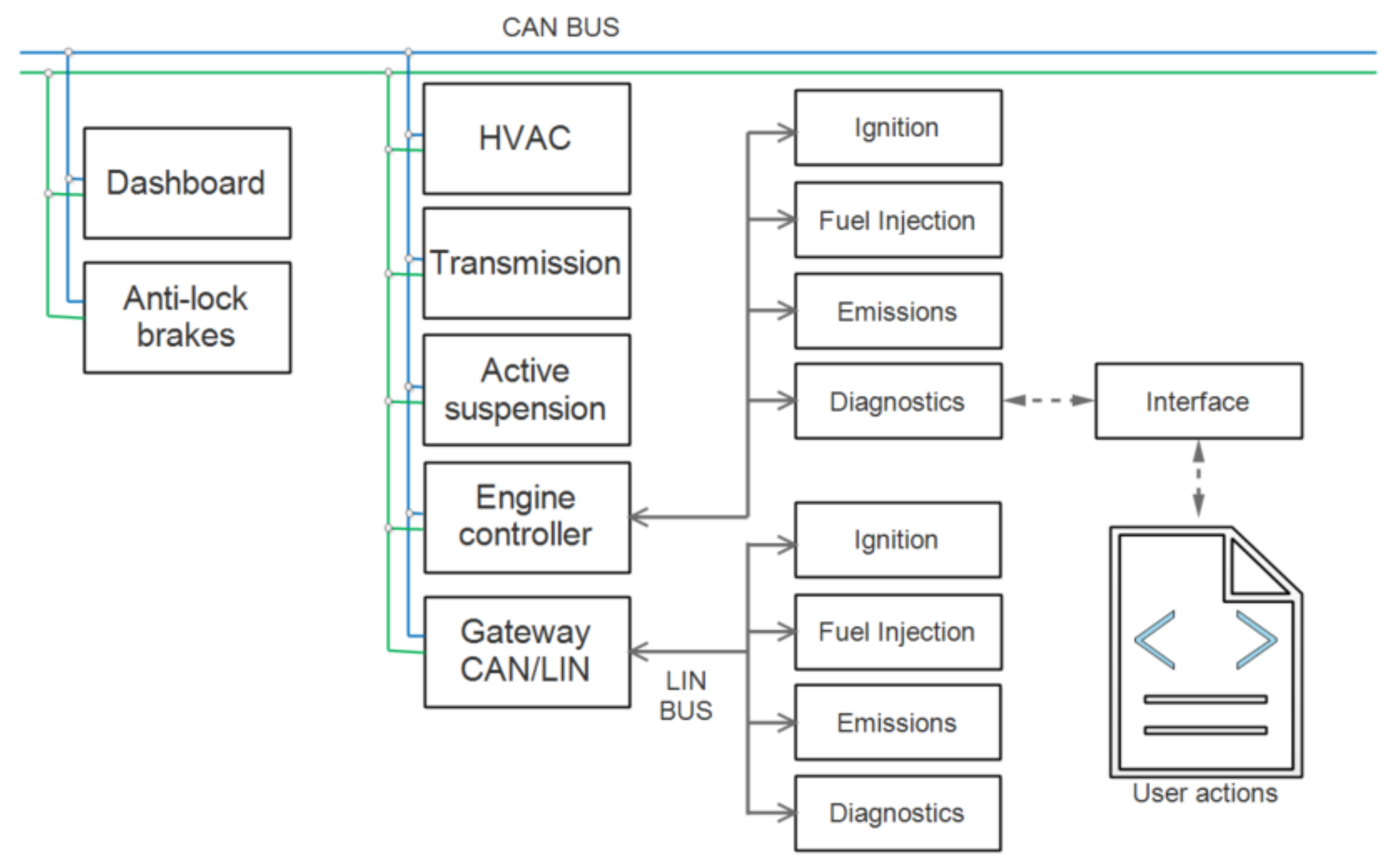
Wireless OBD. Small steps ahead are also implemented in the fault diagnosis area. Interesting research was developed in [10], where a wireless hardware solution, for sending the main parameters read by OBD to a server database, was implemented. It was developed as a local database management system (DBMS) connected wirelessly to the car’s OBD. In [10], the legislation is well documented and summarized according to future trends. In this idea, the authors’ approach is based on three main subsystems (see Figure 1), and software-designed architecture is based on functional units.
The functional units are similar to web services in terms of tasks, but much simpler, with the possibility of being invoked only by the local DBMS. The data flow starts from the protocol interface, which is the first functional unit from the second sub-system (processing unit), it then passes the processing functional unit, and it is prepared for the communication functional unit. In the third subsystem, data are stored and delivered to the user interface. Based on the authors’ conclusion that “the results demonstrate that the system is capable of reading the various parameters, and can successfully process, transmit, and display the readings” [10], this is the starting point of developing our implementation.
On the other hand, as we could see, in the implemented standardized system, data are taken and used locally, without the possibility of making them available for big data or Industry 4.0 solutions. Neither OBD nor DBMS offer a standardized wireless solution for new connectivity trends. Another possible solution has been used in [11] from the data heterogeneity and processing chain point of view.
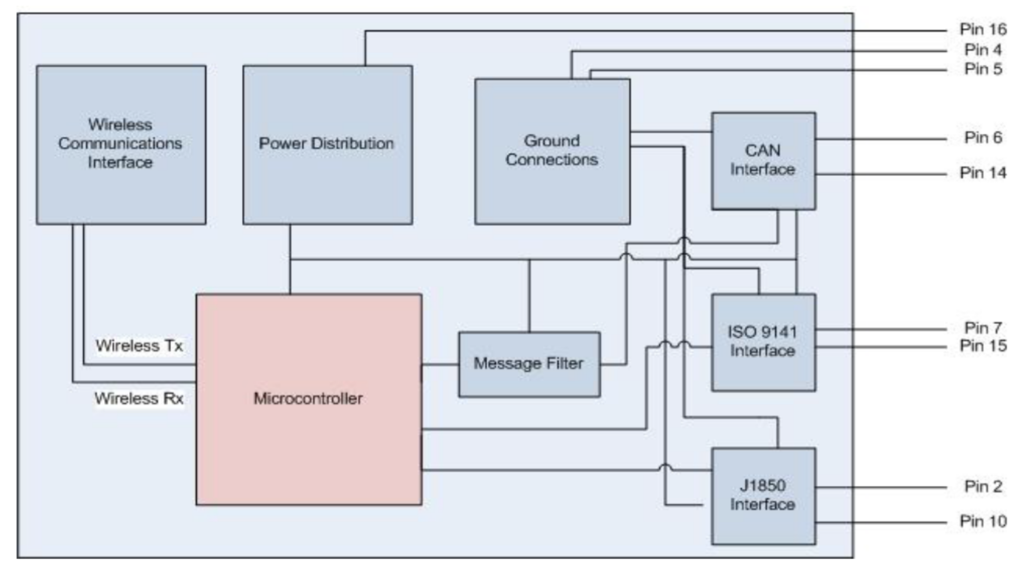
Wireless OBD scanner. Another interesting project was developed by a group of researchers at the Worcester Polytechnic Institute [11]; this group started from the standard specifications (SAEJ1850, responsible for medium transmissions and signal modulation, and ISO 9141-2, responsible for data transfer and its security) and proposed a wireless “dialog” between an electronic control unit (ECU) and OBD, considering that every Controller Area Network (CAN)-based component is an application node. We reproduce their architecture here because it shows the core idea of their approach (see Figure 2).
The main reason for developing a wireless OBD scanner was to ensure the mobility of the car during tests against the processing unit for tester codes. From the list of customer requirements, we reproduce here the most important items as a road map for our implementation: durable and sturdy, informative, having parking-lot-distance wireless capability, easy to use, having a comparable price to wired units, and having a fit current architecture [11]. The proposed architecture looks similar to the first implementation described in this section (see Figure 3). This figure is important because it underlines the necessity of having multiple interface protocols for communication with users’ interfaces. This architecture looks like a gateway between CAN, ISO 9141, and J1850 on one side and remote communication on the other. There is still no possibility of offering compatible data for interconnection with other cars, as mentioned in [2,8].
OBD study management of the common rail engine. This is a specialized application of the OBD system. However, it is very relevant for our work, offering us a clear, stable and unanimously accepted solution for what embedded systems mean for testing and diagnosing this critical component in vehicle operation. In [12], the authors focus on designing an embedded system that is able to more deeply explore the behavior of the diesel-engine common rail. We proved the possibility of acquiring data related to common rail parameters and sending the allowed command to it, through the car’s ECU, all in the local architecture.
Real-time communication for IoT. There are many papers focused on Internet of Things implementation and real-time concepts. We are only interested in research that unifies both topics. In this part of the paper, we will not show technologies used to fit the mentioned purpose. However, we conclude that, with few exceptions, most applications are grouped in the IEEE Digital Library, under the section “Engineering of Computer Based Systems” [13,14]. Being the most relevant database, we have explored it and we want to apply the experience gained here in terms of establishing the relevant framework of the concept of real time in the diagnosis and repair of vehicles.

2. Process Representation—Conceptual Framework

Being a subject that requires hardware and software implementation, the conceptual framework will have to include both the process (by its rigorous definition) and the compatible controller models. As will be seen, the process will be defined by the real-time support function, and will then be tested for compatibility with specific databases. In the analysis of the compatible controller, we will start from the huge Open-Source support existing on the Internet, in terms of implementations. As will be seen, the specialized literature also presents excellent implementations.

2.1. Process Definition

In order to implement a management system for “error codes diagnostic” with high compatibility with new trends, we have formulated a few process requirements. The main requirements are as follows: real-time work and assistance; compatibility with external database sources; and the possibility of receiving updates with a minimum of user intervention.
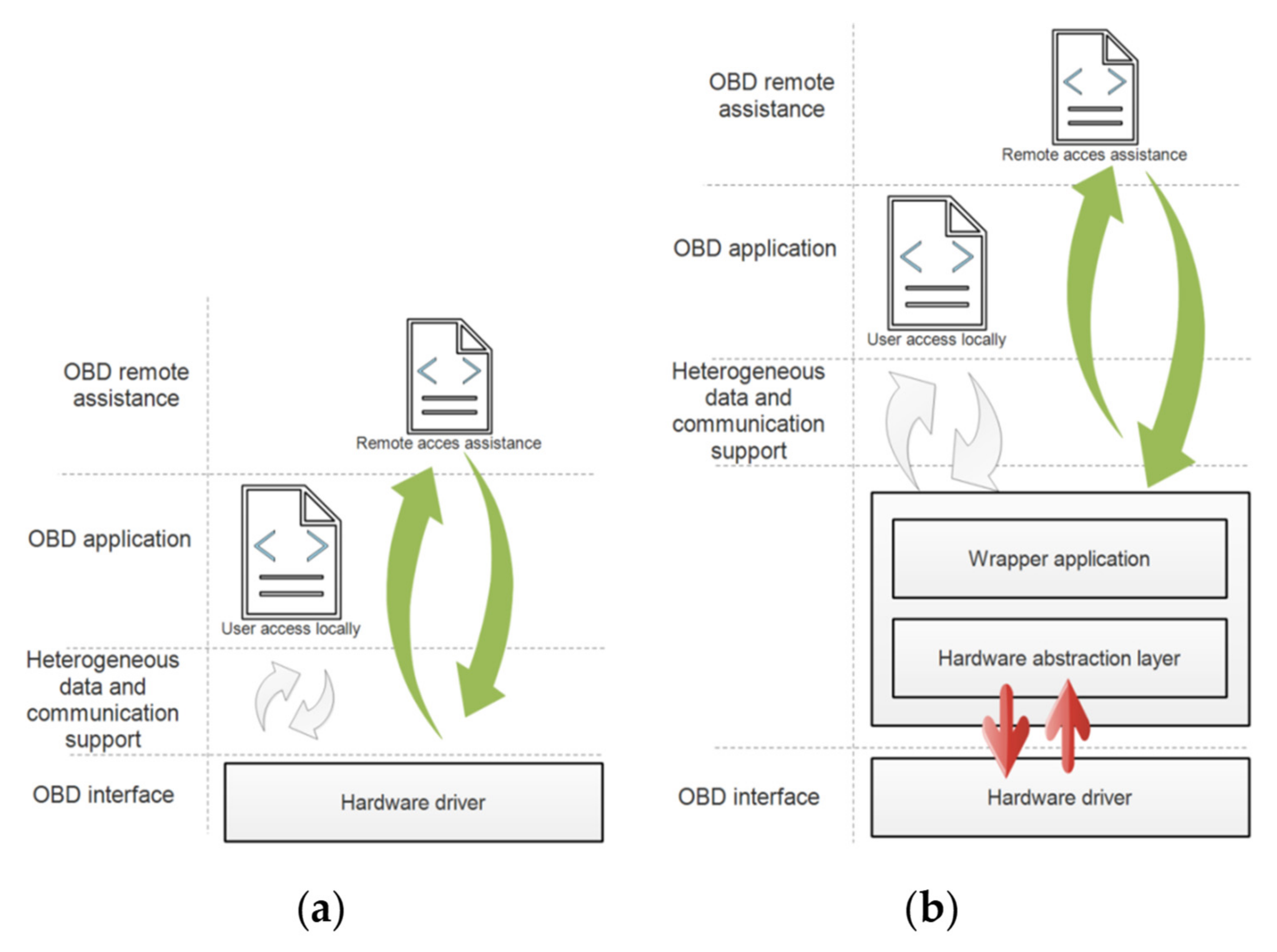
Real-time work and assistance. We have defined this requirement for two issues extracted from [1]. Most of the current developments are based on two-layer architectures (consisting of a server and a client browser) communicating trough Transmission Control Protocol (TCP) in asynchronous mode. On the other hand, through the current programming technologies (Flash, Comet, and Ajax long polling [15]), one cannot create data transfers because many customizations are required on the client side. In [15], this important demand was partially solved in web-based applications using Web Sockets with HTML5. The previous implementations of web applications allowed for the sharing of resources to several clients and access to the object databases. In addition, using both web pooling and socket technologies, reusable connections with real-time transmission were obtained, with specific limitations: restrictions on peer-to-peer connections, validating some redundant data. The application architecture tends to resemble that of the centralized applications. This means that it is moving further from the concept of big data and loses its processing speed. The second part of this requirement is based on the fact that the on-board diagnostics device must manage both local and web-based data exchange. In order to share its resources and data, we designed a representation of a combined applications model (see Figure 4). Based on a three-layer model of the web, and in reference to another researcher [16], we have proposed to add an intermediate layer for mediating between services and data, first of all, and for creating a gateway between protocols (see Figure 4b). For sharing resources in multiple applications, the hardware driver must manage heterogeneous data and communication supports directly (a) or through a “mediator” (b). The abstraction layer provides main descriptors for a special module—called wrapper application—that would be responsible for exchanging data between different applications and services. As we could see, we added specific functions to a latter invoked socket. Moreover, adding an abstraction layer for the hardware will increase the portability of the drivers. At the moment of first research on managing codes returned by the OBD, the driver was very simple, and it responded to a minimum set of commands. It was an excellent idea to keep this limited set of commands for ensuring the highest speed for scanning and returning test codes and, for hardware updates, to implement this abstraction layer. The author of [16] was able to maintain a high speed through this intermediate layer. The creation of six types of services for this abstraction layer was proposed, named as follows: Clock, Tasks, Synchronization, Interrupt Management, Non-Real-Time Signaling, and Utility. In our implementation, we have five of them because, for further development, we consider that we do not have non-real-time events. With a CAN open protocol, we operated in high-speed tests.
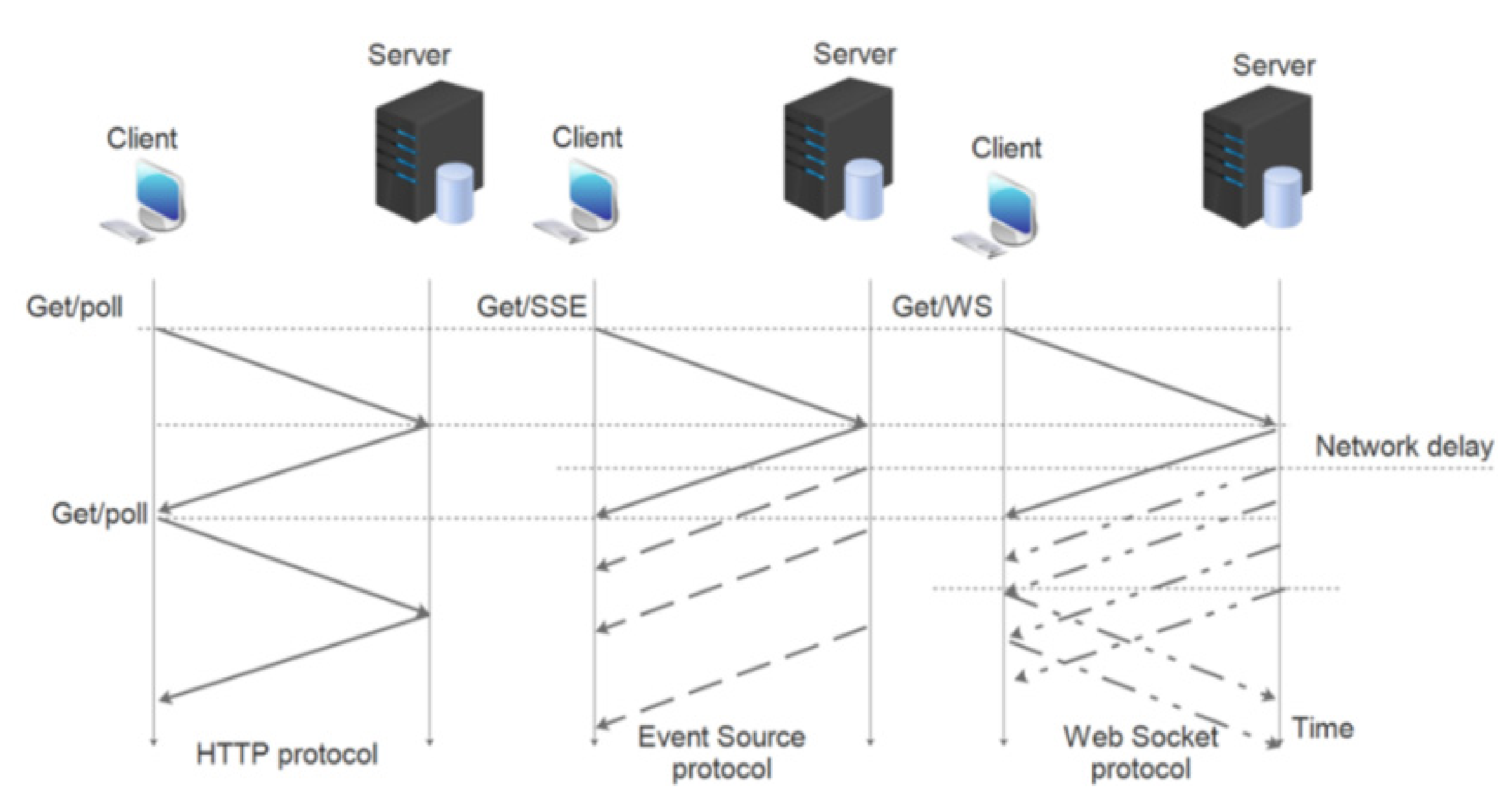
It is possible to receive updates with a minimum of user intervention. Even so, there are many accepted applications that are using such real-time sockets. In [17], there is a fine and clear figure showing differences in these implementations (see Figure 5).
In Server-Sent Event (SSE) architecture, a client sends long-lived requests and, after the server’s reply, switches to a stream receiver. Here, the client does not need to send messages back to the server. In the cases of socket implementation, after the HTTP sequence, streaming from both parts is allowed. Through this implementation, there is an easy way to obtain real-time assistance with a minimum of user intervention. According to the architecture below, the web socket provides a “stream channel wrapper for the WebSocket connections”. It provides a cross-platform WebSocket channel API, a cross-platform implementation of that API that communicates over an underlying channel. It is this experience we are using in our current implementation. Here are the main methods used [18]: socket(), bind(), listen(), accept(), connect(), connect_ex(), send(), recv(), and close(). The pseudo code associated with the socket is very intuitive and easy to implement.
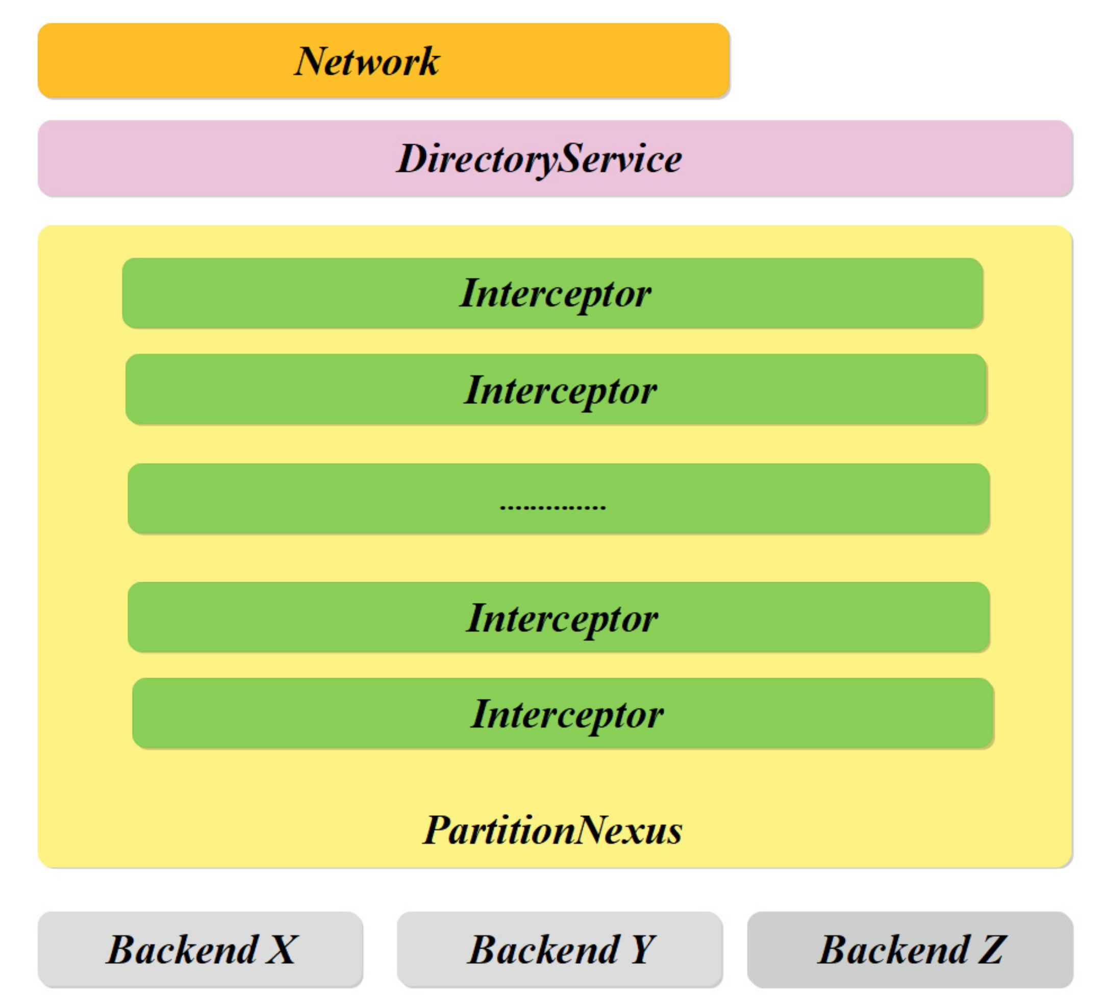
Compatibility with external database sources. In order to exchange information with external sources, following the big data model, first, a local network-based database should be designed. From many open source solutions, we used as support a couple of Apache-MySQL platforms. The architecture of Apache, as a server, is shown in Figure 6. The proposed architecture is using standard interceptor methods at the Network and Directory services layer: Kerberos, Network Time Protocol (NTP), Dynamic Host Configuration Protocol (DHCP), Domain Name System (DNS).
We used this implementation because it has connections to Apache Hadoop, according to the International Business Machines Corporation (IBM) Community’s definition [19]. It is practically the simplest and the most reused definition of big data. Data content is obtained by one or backend servers (Backend X, Y, Z). The client request is sent to one of these backend servers, which then handles the request, generates the content and then prepares the actual response back to the client [20].
As we can see, the network layer might not be a mandatory part of the server. For this reason, we added our solution, which allows for a Python connector to the MySQL server (see Figure 7). One important advantage of using MySQL in our research project is the fact that the same connectors might be used for both Windows day-by-day work and ARM Cortex implementation.

2.2. Process Model Design on ARM Cortex Controller

In order to fit the proposed implementation shown in Figure 4b, where the mediator would run independently of other tasks and interruptions, a processor architecture would have a Direct Memory Access interface. For this reason, from many available open platforms, we decided to use a Broadcom BCM2835 system-on-chip. Its architecture is summarized in Figure 8 and embeds Trust Zone technology [21,22] to execute only secure codes. The SoC based on an ARM Cortex processor has at the hardware level two simultaneously running environments for creating a secure execution channel and a non-secure execution channel. For instance, the SoC BCM2835, equipped with an ARM11J6JZF-S processor, ensures high performance processing according to [18] (Rpi architecture). The SoC BCM2835 is equipped with ARM11J6JZF-S; Arm1176JZ(F)-S is the highest-performance single-core processor in the Classic Arm family [21]. Some additional advantages of using this architecture are based on the fact that its peripheral architecture [21] allows for the addition of external devices through implemented interfaces: Ethernet, USB Ports, HDMI, Display Port, SD card, WiFi, BLE, and GPIO Ports.

3. Software Design—Study Case

The first step in our development was to test the possibilities for optimizing the algorithms presented in [21,22] in the context of our application. Thus, in the framework defined by Berkeley Software Distribution (BSD) Licensing rules, we accessed the application level components of the Raspbian operating system, testing the response of the system created to a diagnosis query based on the connection between its own communication interfaces with the Electronic Control Unit of vehicles. Based on the data obtained, we proceeded to hardware optimization (using only the communication resource with the best results in terms of connection stability and delays), after which, naturally, we proceeded to software optimization (protocols used, how to manipulate work variables, scheduling).

3.1. Algorithm Optimization

Our software implementation uses an architecture typical of Raspberry compatible software (see Figure 8).
This software architecture is compatible with the hardware shown in Figure 8 and Figure 9, supports a wide list of applications through its SPI, UART, I2C, and USB interfaces [23] or networking protocols, and supports an open source library for LTE wireless protocols.

3.2. Hardware-Based Software Optimization

Typical hardware dialog is performed through a typical architecture (see Figure 9).
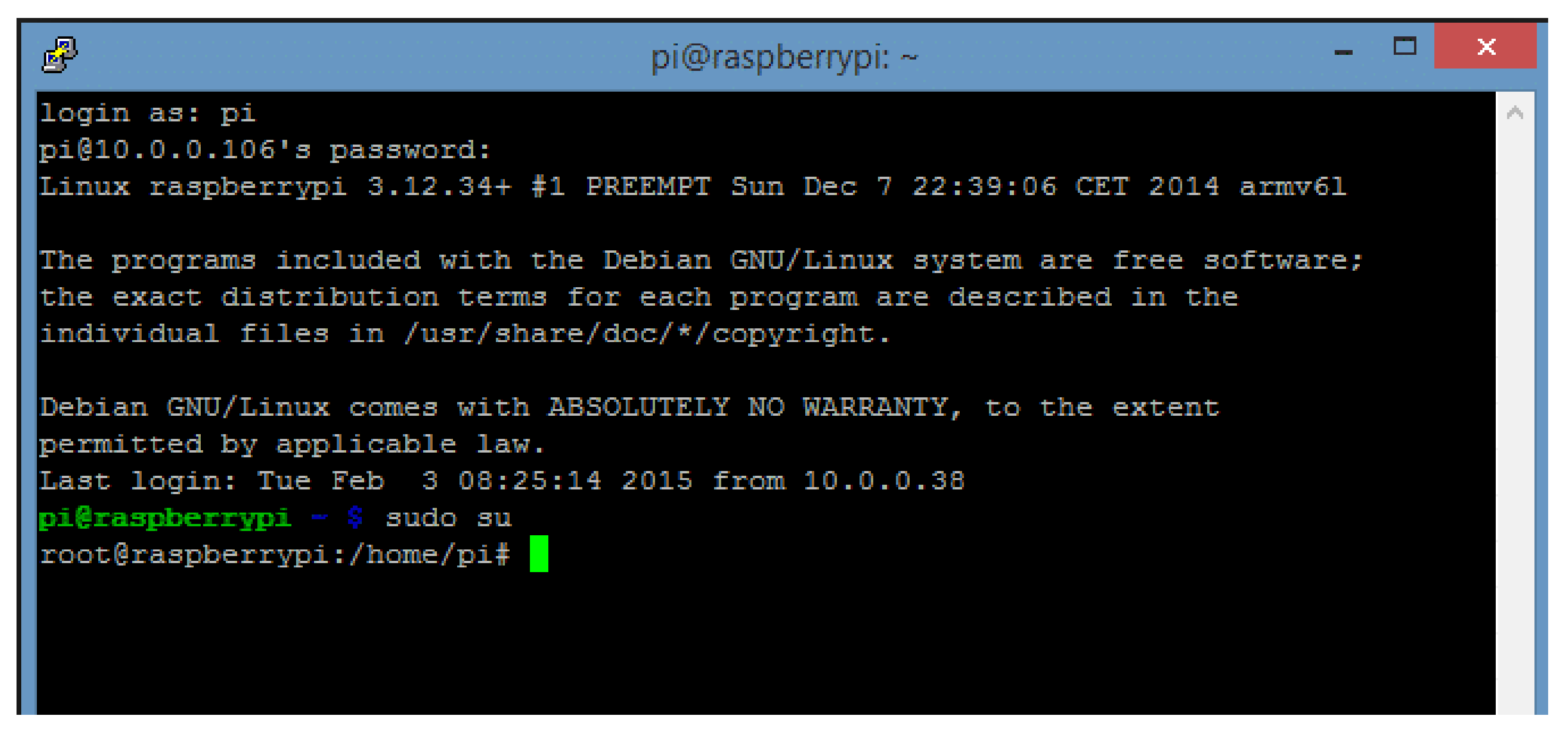
The application from Raspbian invokes the communication driver from its software path (with its Windows OS equivalent) to dialog with the ECU. Three communication environments were tested: using an FTDI device for communication on RS232, Bluetooth and UART, and ELM327 with WiFi. The SSH connection and its interaction with the ARM Cortex controller under Raspbian are shown in Figure 10—a standard command window for logging into the software system.
Some other commands from this interface might be sent to the ECU, e.g., read ECU information, read engine parameters, read error codes, and delete error codes. For a Baud Rate below 115,200, there are no packet losses, nor a necessity to re-interrogate the ECU. When we have replaced the RS232 with Bluetooth, the BLE-to-Serial situation has been changed, and about 20% of the data packets have to be re-interrogated. Through the WiFi environment, because the TCP stack is designed for secure transmission, there were no packet losses, nor any significant delay.

3.3. Software Optimization

To the architecture shown in Figure 11, we added our contribution to adapt the software for communication support for big data. From the excellent presentation of typical IoT architecture [24,25] using Raspbian OS [23], we extracted the part used in our project (see Figure 11). In this figure, we added (in grey blocks) apps to the virtual machine kernel model (because we wanted to run our apps in both Windows and Raspbian Oss simultaneously), we added only preemptive components to the Scheduling model because the OBD now runs rather slowly (keeping in mind that, when we read the CAN, we must also add non-preemptive attributes for the scheduling model), and the user interface or connection to the database are also running with a low refresh rate.
A quite similar approach has been used in [26,27] for adapting the variety of smart grid implementations to the most used IoT protocols, where preemptive and non-preemptive attributes are met according with the differences in communication protocol packets. As the project is in a testing process, the main issue was to maintain the integrity of the shared data. We declared only configuration parameters as static variables (the static allocation of the memory). For the rest of the application parameters, we left them as dynamic variables, because most variables handle complex data (an array of values, also with a variable size).
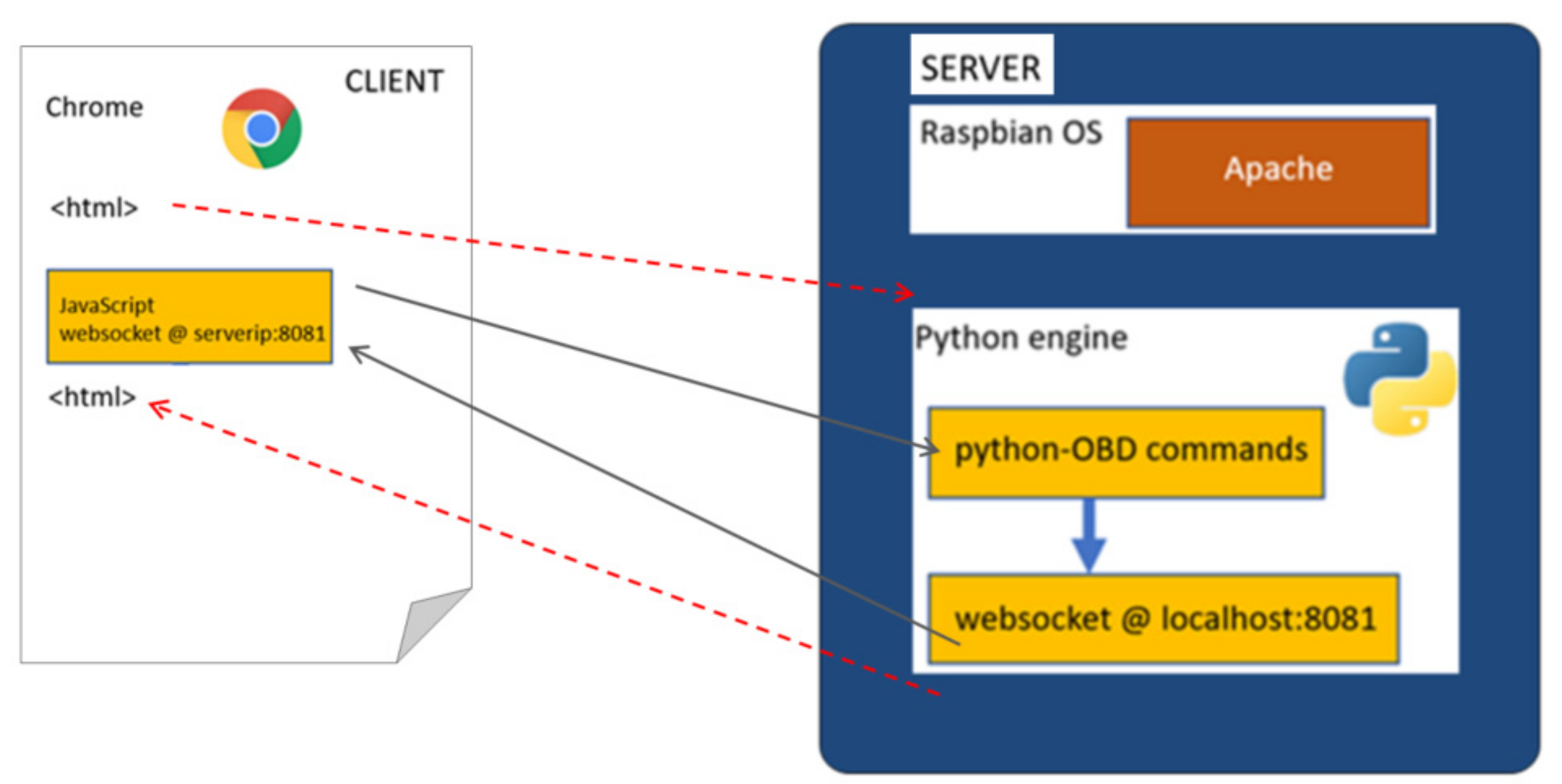
The back-end application—Python-OBD script. The back-end application was made using the Python programming language, the Python interpreter being supported “out-of-the-box” by most Linux-based operating systems. Figure 12 represents the overall structure of the application. For the server side, we used Apache.
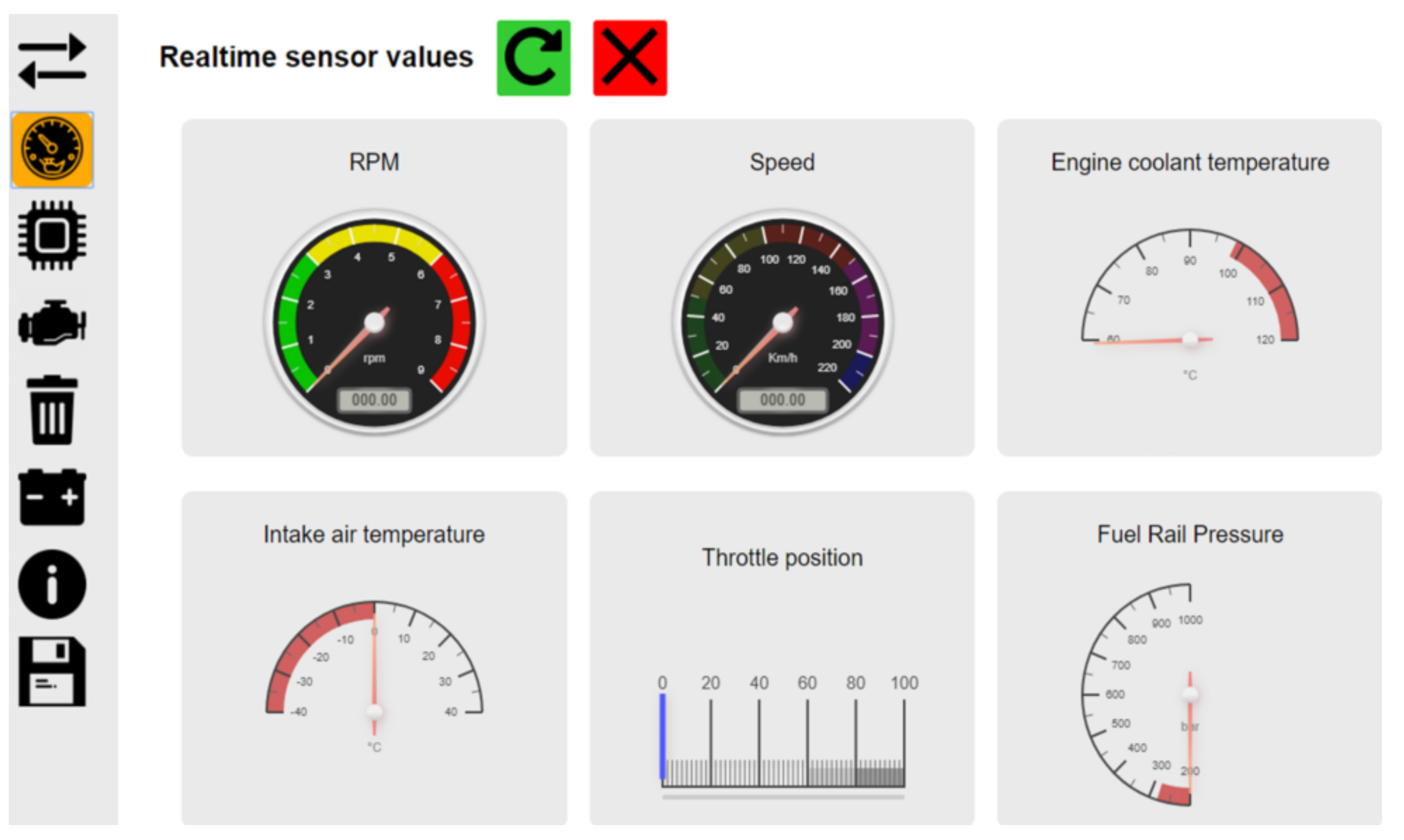
To communicate with the ELM327 interface, we use the Python-OBD library, where the following functions are implemented: obd.OBD, obd.Async, obd.commands, obd.Unit, obd.OBDStatus, obd.scan_serial, obd.OBDCommand, obd.ECU, and obd.logger. Next, we show an example of a function designed for reading in loop data from the ECU. The function below—realtime_data()—extracts real-time values using the diagnostic service “01” from the following sensors: engine speed, vehicle speed, coolant temperature, air intake temperature, acceleration position, and fuel ramp pressure (see Figure 13).
Front-end WEB application. This is a web application with the classic structure of HTML, CSS, and Java script, which can run in most browsers, preferably Chrome or Firefox. The HTML interface is an intuitive one with a menu bar on the left side, containing the main function buttons.

4. Tests Results

According to the previous development and in order to prove the reliability of our work, we have defined a testing procedure for user interaction, connection stability, and delaying. During programming development, we inserted a debugging facility to return into the user’s interface a debugging message every time when there is a communication loss, or when the delay occurs longer than a standard delay of 150 milliseconds.

4.1. User Defined Standard-Based Tests

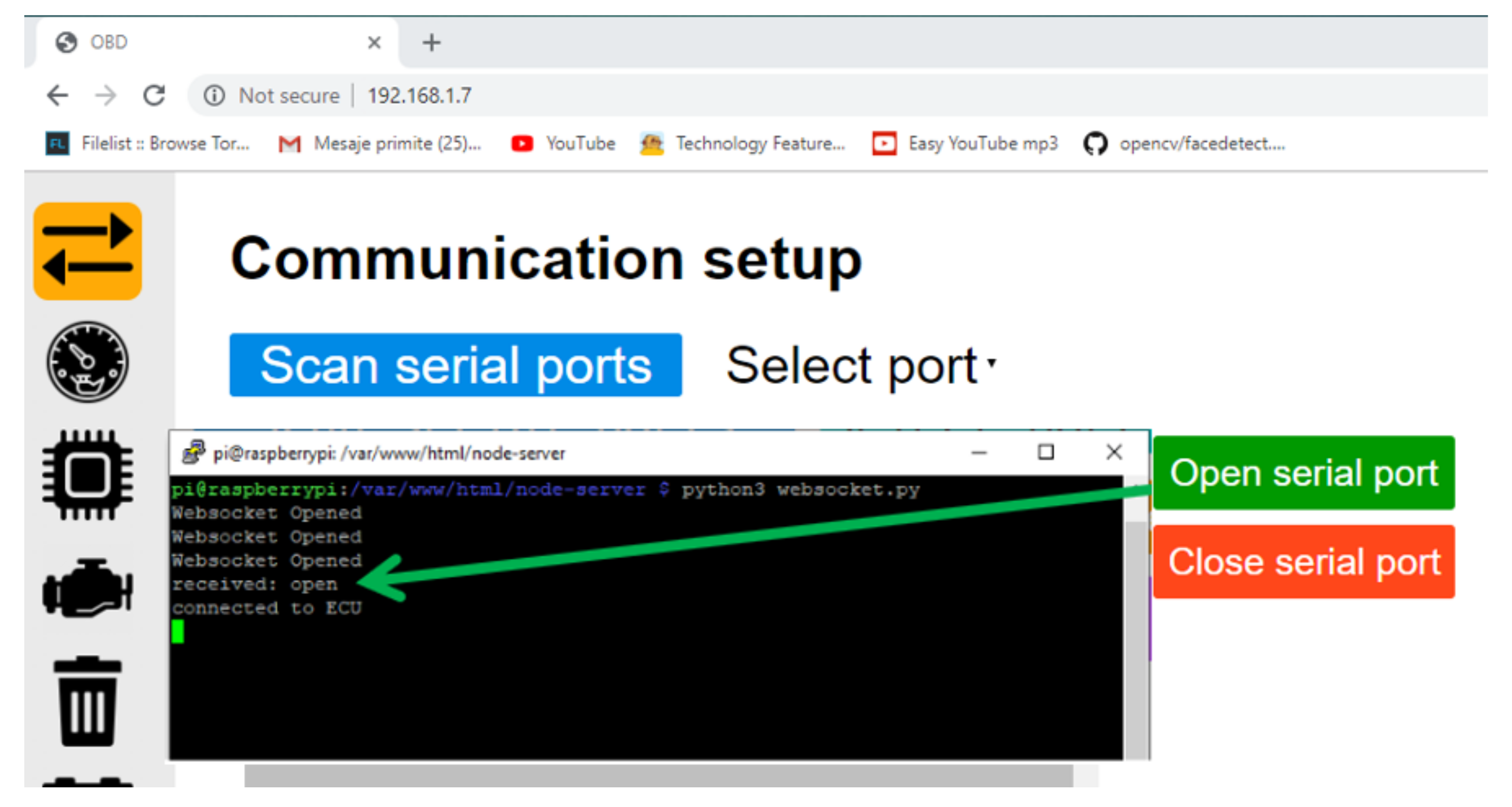
An example of an executed command to the ECU is shown in Figure 14. The connection page with the machine unit contains the buttons that open and close the port. There is also a small window, where a log of each order is recorded.
The Python connection’s function, after connection is established, returns in the status window the clear message. For simplifying the interaction with the user, we decided to simplify the dialog messages, with only interesting information from the user’s point of view.
The test has also been performed for restarting conditions of the ARM Cortex-based hardware, and/or software re-starting. We made this possible by first executing the back-end application—Python OBD script (described in Section 3.3), immediately after the operating system became stable and operable on the ARM Cortex-based architecture. We decided to implement this, as invisibly executable from the user’s point of view, similar to web-based applications.
For real-time reading, after the Python function is executed, it returns values to the JavaScript code, where the messages containing values are retrieved and interpreted. The message is a string, where the values are separated by the “,” character. The specific instructions are used to update the indicators on the page with real-time values (see Figure 15).
When no delays occur (signaling with an associated message in the status window), the Python application returns the parameters’ values required by the groups of indicators. For stability reasons, the method of reading these values is via standard OBD’s implementation.
If an indicator is not updating its parameters in 150 milliseconds, it becomes disabled for inviting the user to switch to the status window to see the returned message. We proved this simply by switching the car key position to “Accessory/Acc-Second Position”, when the Fuel Rail Pressure (RFP) and Engine Coolant Temperature (ECT) gauges became disabled, with the message into the status window (updates FRP exceed 150 ms, updates ECT exceed 150 ms).

4.2. Compatibility Issue Test

The second major part of the test is focused on error treating, according to the error codes database. Our local DBMS is designed with standard indexes, and is open to querying algorithms (to return and diagnose the resulting message) and code library updates (from the web database).
The data transfer is performed wirelessly, in asynchronous mode between the ECU and the Arm Cortex computing system via OBD.
If the code is not contained in our local database, the computing system is connecting to the web databases for checking it and returning into the local system a clear message to the user. Packets carried by the TCP/IP protocol are safe, reliable, and without delays in test code diagnoses and interpretations—no messages in the status window.
If an emerging error code is returned, running error code tests must be performed directly from the CAN interface for complex parameter scanning. In order to separate tasks based on security levels, this will require the addition of non-preemptive attributes for a scheduling model, as described in Section 3.3, and to be in accordance with [22,23]. At this level of implementation, we obtained a clear message at CAN interface level.

5. Conclusions

The ARM Cortex-based hardware, with its dedicated software architecture, is an instrument that allow users to communicate with the computing system for auto vehicles, for parameter querying and on-board diagnostics. It uses its own DBMS, and by executing library updating, the error code’s list and meanings are updated. It is an intelligent gateway that synthesizes web databases with local parameters’ status into the local DBMS by running a back-end set of applications (OBD scripts, library updates, specific SQL conversion scripts).
The wireless system using the TCP-IP protocol is reliable, safe, and easily implemented using ARM Cortex-based architecture. It allows multiple connections, on multipoint systems (wireless OBD and LAN).
The emerging treating situation development needs to be implemented at the front-end user by adding the CAN interface querying into the front-end application, keeping non-pre-emptive attributes as is represented into the scheduling model.
The compact-sized hardware–software implementation does not intend to interfere with the Electronic Control Units or Distributed Control Units from the car. We recommend this implementation to be a processing node, a contributing node to the knowledge base in “connected cars”.
Like all developed technologies under the concept of big data, our prototype is scalable, robust and safe based on the big data standard.
Being an open source prototype, it uses all advantages of this concept including the low cost of implementation (compared with industrial solutions). It is updated according to the desired tasks (including paid error code treating, if needed). There is no need for huge computational resources because error code treating management is supported by big data infrastructure—an optimized querying algorithm allows fast error code treating both locally and remotely.

Author Contributions

Conceptualization, M.R.; Formal analysis, A.A.; Investigation, M.R., R.D. and F.S.; Methodology, R.D. and G.B.; Software, M.R., R.D. and F.S.; Supervision, M.R., R.R. and D.D.M.; Validation, F.S., R.R. and D.D.M.; Visualization, G.B., R.R. and D.D.M.; Writing—original draft, G.B.; Writing—review and editing, A.A., R.R. and D.D.M. All authors have read and agreed to the published version of the manuscript.

Funding

This research received no external funding.

Institutional Review Board Statement

Not applicable.

Informed Consent Statement

Not applicable.

Data Availability Statement

Not applicable.

Conflicts of Interest

The authors declare no conflict of interest.

References

  1. Deloitte. Big Data and Analytics in the Automotive Industry. Automotive Analytics through Piece Report. Available online: https://www2.deloitte.com/content/dam/Deloitte/uk/Documents/manufacturing/deloitte-uk-automotive-analytics.pdf (accessed on 10 March 2019).
  2. Ustundag, A.; Cevikcan, E. Industry 4.0: Managing The Digital Transformation; Springer: Berlin/Heidelberg, Germany, 2018; ISBN 978-3-319-57869-9. [Google Scholar]
  3. Douaioui, K.; Fri, M.; Mabroukki, C.; Semma, E.A. The interaction between industry 4.0 and smart logistics: Concepts and perspectives. In Proceedings of the 2018 International Colloquium on Logistics and Supply Chain Management (LOGISTIQUA), Tangier, Morocco, 26–27 April 2018; pp. 128–132. [Google Scholar] [CrossRef]
  4. SAE J1930. Available online: https://law.resource.org/pub/us/cfr/ibr/005/sae.j1930.2002.pdf (accessed on 12 July 2019).
  5. Brando, G.; Dannier, A.; del Pizzo, A.; Rizzo, R. Power Electronic Transformer for advanced grid management in presence of distributed generation. Int. Rev. Electr. Eng. 2011, 6, 3009–3015. [Google Scholar]
  6. Rizzo, R.; Tricoli, P.; Spina, I. An innovative reconfigurable integrated converter topology suitable for distributed generation. Energies 2012, 5, 3640–3654. [Google Scholar] [CrossRef]
  7. Di Noia, L.P.; Genduso, F.; Miceli, R.; Rizzo, R. Optimal integration of hybrid supercapacitor and IPT system for a free-catenary tramway. IEEE Transa. Ind. Appl. 2019, 55, 794–801. [Google Scholar] [CrossRef]
  8. Eascy, Five Trends Transforming the Automotive Industry. Available online: www.pwc.com/auto (accessed on 22 July 2019).
  9. Morimoto, T. Connectivity and Big Data Analytics in Automotive; ICT Outlook Executive Briefing; Frost & Sullivan: New York, NY, USA, 2015. [Google Scholar]
  10. Malekian, R.; Moloisane, N.R.; Nair, L. Design and Implementation of a Wireless OBD II Fleet Management System. IEEE Sens. J. 2017, 17, 1154–1164. [Google Scholar] [CrossRef] [Green Version]
  11. Keenan, J. Creating A Wireless OBDII Scanner, Project Number: MQP-SJB-4C09. Available online: https://web.wpi.edu/Pubs/E-project/Available/E-project-043009-154526/unrestricted/JOHNKEENANIIIMQP2009.pdf (accessed on 15 February 2020).
  12. Risteiu, M.; Dobra, R. Designing Dedicated Electronic Systems—Mechatronics Embedded System; Universitas Publishing House: Petrosani, Romania, 2019; ISBN 978-973-741-618-6. [Google Scholar]
  13. Darwish, A.; Lakhtaria, K.I. The Impact of the New Web 2.0 Technologies in Communication, Development, and Revolutions of Societies. J. Adv. Inf. Technol. 2011, 2, 204–216. [Google Scholar] [CrossRef] [Green Version]
  14. Hayes, B. Cloud Computing. Commun. ACM 2008, 51, 9–11. [Google Scholar] [CrossRef] [Green Version]
  15. Liu, Q.; Sun, X. Research of Web Real-Time Communication Based on Web Socket. Int. J. Commun. Netw. Syst. Sci. 2012, 5, 797–801. [Google Scholar] [CrossRef] [Green Version]
  16. Kiszka, J. The Real-Time Driver Model and First Applications. Available online: http://www.cs.ru.nl/lab/xenomai/RTDM-and-Applications.pdf (accessed on 22 July 2019).
  17. Grigorik, I. High Performance Browser Networking; O’Reilly Media, Inc.: Sevastopol, CA, USA, 2013; Available online: https://hpbn.co/ (accessed on 22 July 2019).
  18. Jennings, N. Socket Programming in Python (Guide). Available online: https://realpython.com/python-sockets/ (accessed on 23 July 2019).
  19. Nakamura, G. Why Hadoop Only Solves a Third of the Growing Pains for Big Data. Available online: https://www.wired.com/insights/2014/01/hadoop-solves-third-growing-pains-big-data/ (accessed on 23 July 2019).
  20. Apache Directory. Available online: https://directory.apache.org/apacheds/advanced-ug/1.5-backend.html (accessed on 20 May 2019).
  21. Raspberry Pi Architecture. Available online: https://www.macs.hw.ac.uk/~hwloidl/Courses/F28HS/slides_RPi_arch.pdf (accessed on 22 May 2019).
  22. BCM2835 Documentation. Available online: https://www.raspberrypi.org/documentation/hardware/raspberrypi/bcm2835/README.md (accessed on 20 May 2019).
  23. The MagPi Magazine. Available online: https://www.raspberrypi.org/magpi/tutorials/ (accessed on 2 September 2019).
  24. Nayyar, A.; Puri, V. Raspberry Pi-A Small, Powerful, Cost Effective and Efficient Form Factor Computer: A Review. Int. J. Adv. Res. Comput. Sci. Softw. Eng. 2015, 5, 720–737. [Google Scholar]
  25. Qutqut, M.H.; Al-Sakran, A. Comprehensive survey of the IoT open source Oss. IET Wirel. Sens. Syst. 2018, 8, 323–339. [Google Scholar] [CrossRef]
  26. Tuan, C.C.; Lu, C.H.; Wu, Y.C.; Yeh, W.L.; Chen, M.C.; Lee, T.F.; Chen, Y.-J.; Kao, H.-K. Development of a System for Real-Time Monitoring of Pressure, Temperature, and Humidity in Casts. Sensors 2019, 19, 2417. [Google Scholar] [CrossRef] [Green Version]
  27. Viel, F.; Augusto Silva, L.; Leithardt, V.R.Q.; De Paz Santana, J.F.; Celeste Ghizoni Teive, R.; Albenes Zeferino, C. An Efficient Interface for the Integration of IoT Devices with Smart Grids. Sensors 2020, 20, 2849. [Google Scholar] [CrossRef] [PubMed]
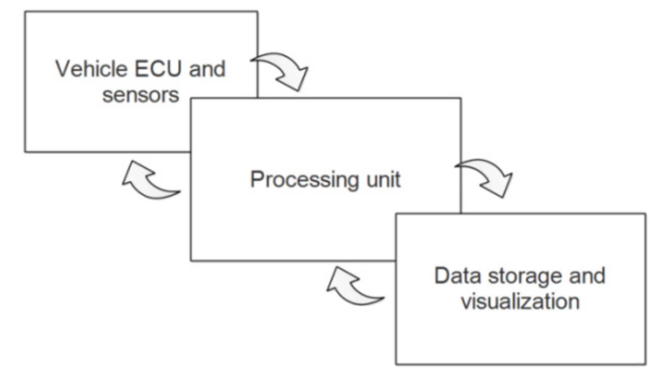
Figure 1. According to [10], all three subsystems are interconnected, and they are exchanging information.
Energies 14 03300 g001
Figure 2. The vehicle nodes and network structure connected to the Controller Area Network (CAN) [10]. The user actions are accessible through the diagnosis interface.
Energies 14 03300 g002
Figure 3. The vehicle data network structure connected to the CAN [11].
Energies 14 03300 g003
Figure 4. Designed architecture of a three-layer model for communications between services and data: managed directly (a) or through a mediator (b) by the hardware driver.
Energies 14 03300 g004
Figure 5. Architecture implementation of the Client Server for duplex communication [16]: Single request and a single reply (HTTP protocol), a Server-Sent Event (SSE), and web socket (WS).
Energies 14 03300 g005
Figure 6. General architecture of the developed Apache Backend.
Energies 14 03300 g006
Figure 7. The logical architecture of the MySQL server [18] allows connection and thread handling by both PHP and Python connectors under many operating systems (main layer accessed by client), including Debyan and Raspbian OS; the bottom layer represents responsible functions for MySQL database querying.
Energies 14 03300 g007
Figure 8. The architecture of the Raspbian OS [23] based on the Berkeley Software Distribution (BSD) Licensing rules.
Energies 14 03300 g008
Figure 9. The hardware architecture composed by the OBD adapter (ELM 327) of the electronic control unit (ECU) of the car, connected through a communication environment to the controller ARM Cortex where Raspbian OS runs.
Energies 14 03300 g009
Figure 10. Logging into the software system through a command window.
Energies 14 03300 g010
Figure 11. The adapted figure from [22] required in our implementation architecture.
Energies 14 03300 g011
Figure 12. The application level architecture of the designed client server architecture.
Energies 14 03300 g012
Figure 13. Part of real-time designed reading function in Python.
Energies 14 03300 g013
Figure 14. When the communication button is hinted, a scan action is executed, and the status result is displayed.
Energies 14 03300 g014
Figure 15. The indicators were made using the canvas-gauges source.
Energies 14 03300 g015
Publisher’s Note: MDPI stays neutral with regard to jurisdictional claims in published maps and institutional affiliations.