Abstract
Many leading companies in the automotive industry have been putting tremendous effort into developing new powertrains and technologies to make their products more energy efficient. Evaluating the fuel economy benefit of a new technology in specific powertrain systems is straightforward; and, in an early concept phase, obtaining a projection of energy efficiency benefits from new technologies is extremely useful. However, when carmakers consider new technology or powertrain configurations, they must deal with a trade-off problem involving factors such as energy efficiency and performance, because of the complexities of sizing a vehicle’s powertrain components, which directly affect its energy efficiency and dynamic performance. As powertrains of modern vehicles become more complicated, even more effort is required to design the size of each component. This study presents a component-sizing process based on the forward-looking vehicle simulator “Autonomie” and the optimization algorithm “POUNDERS”; the supervisory control strategy based on Pontryagin’s Minimum Principle (PMP) assures sufficient computational system efficiency. We tested the process by applying it to a single power-split hybrid electric vehicle to determine optimal values of gear ratios and each component size, where we defined the optimization problem as minimizing energy consumption when the vehicle’s dynamic performance is given as a performance constraint. The suggested sizing process will be helpful in determining optimal component sizes for vehicle powertrain to maximize fuel efficiency while dynamic performance is satisfied. Indeed, this process does not require the engineer’s intuition or rules based on heuristics required in the rule-based process.
1. Introduction
In recent years, automotive powertrains have been rapidly electrified in order to achieve low emissions and high fuel efficiency. Despite the intensive development of electric vehicles (EVs) in the industry, EVs still have limitations due to the decreasing range in cold temperatures [1]. For this reason, the hybrid electric vehicle (HEV) remains one of the most promising candidates for next-generation vehicle powertrains. Hybrid electric vehicles have more than two power sources; typically, an engine and a motor powered by battery [2]. Plug-in hybrid vehicles (PHEV) have the advantages of both HEV and EV, by adopting a power charging unit so that they can operate both modes depending on the situation [3,4,5]. Fuel cell electric vehicles (FCEV) are also one of the promising candidates. Since the FCEV uses hydrogen as fuel, emission is zero except pure water (H2O), and the problem of EV with respect to charging time can be solved [6,7,8]. Although the FCEV is a great powertrain with many advantages, it has limitations in terms of cost and infrastructure [9].
When developing all kinds of powertrains as well as HEVs, carmakers make great efforts to design energy-efficient vehicles while satisfying specific dynamic performance, such as acceleration performance and maximum speed. Component sizing is a very important piece of the design puzzle-process of satisfying performance goals.
Many research efforts have sought to address the component-sizing problem. In [10], a rule-based sizing algorithm is applied for various vehicle types, ranging from a conventional vehicle to an HEV, a plug-in HEV (PHEV), and a battery electric vehicle (BEV). Each sizing philosophy is applied for different powertrain configurations. For example, in conventional vehicles, engine power is sized to meet and pass acceleration performance measures. However, in an HEV, battery power is sized to recuperate 100% of energy on the Urban Dynamometer Driving Schedule (UDDS) cycle. Component sizing on a backward-looking simulation based on dynamic programming (DP) is conducted in [11]. The sizes of an engine, two electric motors, and reduction gear ratios are optimized to maximize fuel economy performance for the drivetrains studied. DP is used to find the best fuel economy performance in specific component size configurations, assuming the use of an optimal energy management strategy (EMS). In [12], drivetrain cost is minimized over three different all-electric-range vehicles and two types of batteries for PHEVs. Parallel chaos optimization is used as the component-sizing algorithm while satisfying driving performance requirements are used as constraints. For plug-in hybrid vehicles in [13], a rule-based fuzzy logic and genetic algorithm was used for optimization of component sizing, minimizing weighted fuel consumption and exhaust gas emissions. In [14], the component-sizing process is conducted for a plug-in hybrid electric bus using a rule-based sizing algorithm and the energy management strategy with a gen-set optimal operating line and a rule-based algorithm. In [15], based on the assumption that the powertrain model represents quadratic losses for powertrain components, the researchers formulate the problem as a convex optimization problem to minimize fuel consumption, electrical energy, and component cost.
In the component-sizing problem for vehicle powertrains, it is hard to obtain the derivative of an objective function because of the complexity of the powertrain structure and its highly nonlinear characteristics. For this reason, most research has applied a rule-based or brute-force algorithm as the component-sizing algorithm. However, some research applied an optimization algorithm under only specific assumptions (e.g., powertrain loss can be represented as a quadratic function).
In the HEV system, the energy management strategy is very important in terms of fuel efficiency. In particular, it is important to apply optimal control logic so that the effect of the EMS on each parameter configuration will be fair. Therefore, many studies have applied mainly backward-looking simulations that enable the application of dynamic programming, which guarantees globally optimal results. However, DP requires a huge amount of computation time because it solves all possible controls. In addition, a backward-looking simulation has the disadvantage that it does not represent the dynamics of the supervisory controller, nor does it represent the sub-controller at the component level of the vehicle.
Two studies perform component sizing using a sizing algorithm called Practical Optimization Using No Derivatives for sums of Squares (POUNDERS), which is also used in this study. One of these studies minimizes ownership cost in fuel cell vehicles [16], and the other applied POUNDERS to the component-sizing problem to minimize fuel consumption while satisfying the dynamic performance as a requirement [17]. The target vehicle powertrains are those of a conventional vehicle and an HEV, and a rule-based energy management strategy was applied. Therefore, for different parameter configurations of vehicle powertrains, one limitation is that the impact of fuel economy of a rule-based EMS may not be fair.
For this reason, in this study, we apply Pontryagin’s Minimum Principle (PMP) to EMS as a real-time control logic that can be applied to a forward-looking simulation while ensuring optimality close to DP results when certain necessary conditions are satisfied in the EMS problem of HEVs. Applying this PMP guarantees a fair comparison, and the dynamics of the vehicle can be considered by constructing a forward-looking simulation. We used the sizing algorithm which is an optimal algorithm called POUNDERS. Existing rule-based algorithms that optimize fuel economy performance while satisfying the constraints require engineer’s intuition or design heuristics, because an appropriate algorithm must be used according to each powertrain structure. However, the POUNDERS algorithm, which is a black-box optimization method, performs optimization using the cost function value, so it can be applied to all types regardless of the powertrain structure.
2. Vehicle Modeling Methodology
The target vehicle in this study is the power-split hybrid system shown in Figure 1. The planetary gear as a power-split device is connected to the engine and motors and drive shaft, respectively. This power-split powertrain has been improved upon from one of the most well-known systems, the Toyota Hybrid System (THS) [18,19]. This version has been improved by the addition of a one-way clutch to the carrier of the planetary gear, which enables the generator to assist the drive force, unlike in the previous version [20]. Table 1 lists the vehicle specification data used in this study. We obtained this data and vehicle model from Autonomie, a simulation tool developed by Argonne National Laboratory(Lemont, United States) [21,22]. Because of the layout of the Autonomie program we used, we call some specific components by abbreviations for general components. For instance, the planetary gear as the power-split device is called GB, which stands for gearbox, because the planetary gear performs the role of a gearbox in that it transmits engine power to the drive shaft. The motor reduction gear is called TC, which stands for torque coupling, and the final drive reduction gear is called FD. In 2019, we tested and validated the vehicle model and controller model with the test data [23].
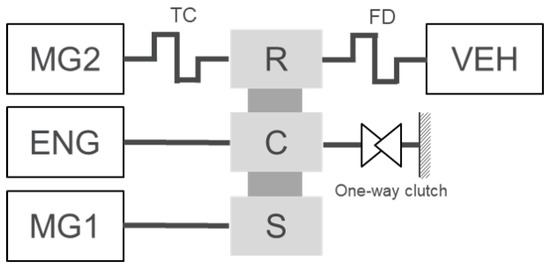
Figure 1.
Schematics of the powertrain.

Table 1.
Vehicle model parameters.
3. Component-Sizing Methodology Using the Optimization Algorithm
In this study, the component-sizing optimization process was developed by applying PMP and POUNDERS to the EMS and component-sizing algorithm, respectively, in a forward-looking simulation framework. For the initial parameter, we calculated the fuel consumption using the forward-looking simulation model to which PMP is applied; and through these results, the POUNDERS algorithm updates the parameter to find the optimum value shown in Figure 2. While repeating this process, the process terminates when the parameter converges or the iteration exceeds the maximum value.
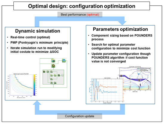
Figure 2.
Component-sizing optimization process with vehicle simulation. The POUNDERS algorithm updates the parameter configuration to minimize the cost function value and vehicle simulation, with PMP runs targeting the driving cycles with updated parameter configurations from POUNDERS.
3.1. Pontryagin’s Minimum Principle
PMP is an optimal control strategy that can be applied to systems that are nonlinear and non-differentiable, such as hybrid electric vehicle powertrains. PMP does not require much calculation time because it provides a simple solution while ensuring optimality when certain conditions are satisfied. It is derived from the Euler–Lagrange equation in Calculus of Variation. Optimality is satisfied only when the necessary conditions are obtained and satisfied [24]. Following are general PMP applications to HEVs [25].
The performance index can be defined as:
where g(Pb,t) is the best fuel consumption rate function, which is a function of Pb and t. Pb and t are battery output power and time, respectively. The Hamiltonian is defined as:
where p is a costate. is state of charge of battery. The state equation and the costate equation are described as:
Researchers should consider Equation (5) as determining optimal control variable at every time step.
As a boundary condition, in the optimal control problem of HEV, initial SOC and final SOC should be the same:
These necessary conditions and boundary conditions must be satisfied for determining the optimal trajectory.
3.2. POUNDERS
In this study, we used the derivative-free optimization algorithm called POUNDERS for component parameter optimization, which has been developed by Argonne National Laboratory [26]. Vehicle simulation models are complex systems and consist of numerous components, and each component has a controller model. Because of the high nonlinearity of the control models and component performance curves, obtaining gradient and hessian information related to component-sizing parameters is very difficult. For a black-box optimization problem such as the component-sizing problem, instead of using finite-difference approximations, the algorithm uses quadratic surrogate models to determine the coarse approximations for the unknown gradient and hessian terms. This approach has been shown to be efficient for minimizing the number of required simulation runs.
In this study, we optimized three gear ratios—final drive, TC and GB—to minimize combined fuel consumption on the Urban Dynamometer Driving Schedule (UDDS) and Highway Fuel Economy Test (HWFET). We calculated combined fuel economy as a harmonic mean of fuel economy on the UDDS and HWFET weighted 55% and 45%, respectively [27,28]. We considered dynamic performance using constraints such as acceleration time from 0 to 100 km per hour (kph) and missing time proportion for tracing each driving cycle within 3.2 kph. We formulated the component-sizing optimization problem as follows [17]:
where is fuel consumption on each driving cycle. It is minimized over whose range is from to , which are the lower limit and upper limit, respectively. represents the dynamic performance constraints, and represents different constraints. represents different components whose parameter is updated by the algorithm. For given Lagrange multipliers and the penalty parameter, a bound-constrained augmented Lagrangian problem can be formulated as follows:
where is a cost function, is an estimate of Lagrangian multipliers, are slack variables, and is the penalty parameter. When the constraints are not satisfied (e.g., acceleration time is above the target value), the slack variables increase the cost function value, , and the point is excluded from the feasible points.
4. Simulation and Results
The POUNDERS optimization process finds a parameter configuration that minimizes the combined fuel economy while satisfying the dynamic performance constraints of an acceleration time of 9.3 s and a driving cycle tracing error of 3.2 kph. Although they are not the target parameters in this study, battery and motors have a great influence on dynamic performance and fuel economy in hybrid electric vehicles. Therefore, we determined their minimum size to satisfy the following conditions and considered the weight change according to the power of the motor and battery based on our previous research [10]. We sized battery power and electric machine MG1 power to recuperate 100% of the energy through regenerative braking on UDDS, and we sized electric machine power to meet the gradeability and performance requirements. We defined vehicle weight as a function of the peak power of electric machine and battery cell number under the assumption that the specific power density of the electric machine is 1440 W/kg and of the battery is 2750 W/kg.
Since the initial costate in PMP has great influence on the final SOC, it is important to find the initial costate that matches the final SOC with the initial SOC in the HEVs. To this end, we iterate the simulation in the parameter set determined by POUNDERS, in order to find the initial costate that makes the SOC deviation close to 0. It is terminated when it converges below a certain tolerance or reaches the maximum number of iterations. If it is terminated due to the maximum iteration number, fuel consumption is estimated through linear approximation, as shown in Figure 3.
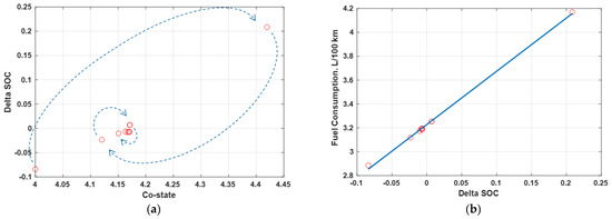
Figure 3.
SOC deviation correction method: (a) co-state correction; and (b) linear approximation method.
First, component-sizing optimization was performed for three cases in which two out of three parameters were paired. The objective is to find the optimal values of a parameter set for the three gear ratios—GB, TC, and FD—that minimizes fuel consumption. Table 2 shows the parameter combinations and ranges of the three cases. For example, in Case 1, the optimal values of GB and TC that minimize fuel consumption are found, and the FD value, which is not a target parameter, is fixed as the original value from Table 1. The two-parameter optimization case was performed as a preliminary task to confirm the optimization performance of the sizing algorithm and to determine the range in the three-parameter optimization case. For this, we set parameter ranges that best show the algorithm’s optimization performance and trend.
Table 2.
Lower and upper ranges of parameters.
The result of component-sizing optimization for Case 1 follows. Figure 4 shows the resulting values of acceleration time and fuel consumption within a given parameter range in the proposed component-sizing optimization process. By dividing each parameter range by seven points, a total of 49 points were obtained. In order to confirm the optimization performance of the POUNDERS algorithm, we obtained fuel consumption and acceleration performance results in all domains for only two parameter cases. As required constraints, points that satisfy the acceleration time and profile speed of the driving cycle speed are indicated as feasible points. As Figure 4a shows, the GB value does not have a significant effect on the acceleration performance, and the larger the TC value, the better the acceleration performance. When the value of the TC ratio acting as the reduction gear ratio of the motor is large, the torque increases during the initial acceleration situation, and the acceleration performance tends to be improved. Figure 5. Cost function value contour and parameter optimization history versus TC and GB. shows the optimization history through the component-sizing process using POUNDERS. In order to confirm the optimality of the POUNDERS result, the value of the cost function h(r, s) is derived in Figure 5 through Equation (8) using the fuel consumption values in Figure 4b and the acceleration time value in Figure 4a. The optimized values are 2.525 and 3.563 for the GB and TC ratios, respectively (Figure 6). Table 3 shows the optimized parameter values for Case 1, and Table 4 summarizes the fuel consumption results, SOC changes, and acceleration performance results for all cases. To adjust the fuel consumption results resulting from the SOC difference, the adjusted fuel consumption was calculated by interpolation using linear approximation as described in Figure 3. The fuel consumption for Case 1 is 3.511 L/100 km for the combined cycle, which is an improvement compared to 3.527 L/100 km for the non-sized case.
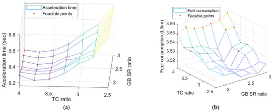
Figure 4.
Results on entire range versus TC and GB and feasible points: (a) acceleration results; and (b) fuel consumption results.
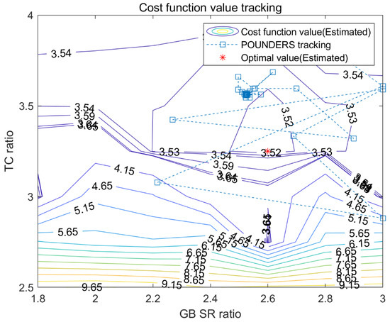
Figure 5.
Cost function value contour and parameter optimization history versus TC and GB.
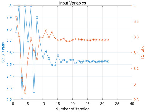
Figure 6.
Optimization results for the TC(orange, asterisk) and GB(blue, cube) ratios.
Table 3.
Component-sizing results and acceleration performance for Case 1.
Table 4.
Fuel consumption and acceleration time results for UDDS and HWFET and combined.
The result of parameter optimization in Case 2 is as follows. As with Case 1, Figure 7 shows the 49 acceleration time (a) and fuel consumption (b) results in the entire parameter range, and Figure 8 shows the cost function value and tracking history of the optimization process in all areas. Similar to Case 1, the GB value does not have a significant effect on the acceleration performance, and the results show that the larger the FD value, the better the acceleration performance. Not only the TC value but also the FD value should be large so that the wheel torque increases during the initial acceleration, and the acceleration performance tends to be improved. The optimized values are 2.838 and 3.028 for the GB and FD ratios, respectively (Figure 9). Table 4 and Table 5 show the optimized parameter values for Case 2 and fuel consumption results for all cases, respectively. The fuel consumption is 3.505 L/100 km for combined cycle, which is an improvement compared to 3.527 L/100 km for the non-sized case.
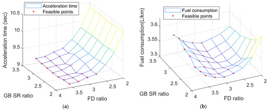
Figure 7.
Results on entire range versus GB and FD and feasible points: (a) acceleration results; and (b) fuel consumption results.
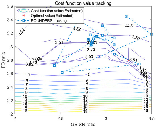
Figure 8.
Cost function value contour and parameter optimization history versus GB and FD.
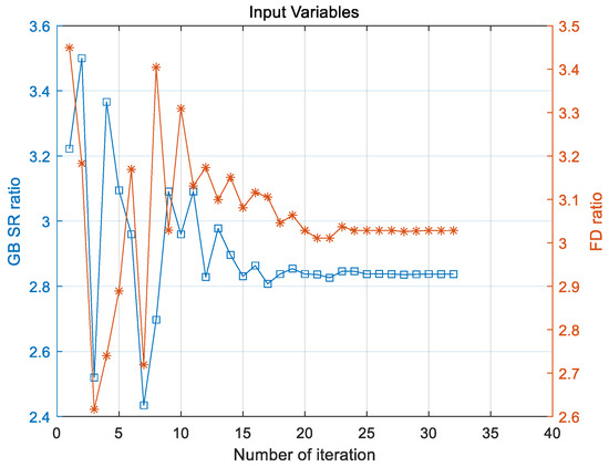
Figure 9.
Optimization results for GB(blue, cube) and FD(orange, asterisk) ratios.
Table 5.
Component-sizing results and acceleration performance for Case 2.
Figure 8 shows that there can be multiple locally optimal solutions for this optimization problem. Moreover, if the grid is set to be denser than 7 by 7, more locally optimal solutions can exist. This result shows that, although the POUNDERS algorithm cannot always guarantee the globally optimal point, it does find a locally optimal point that is quite similar to the globally optimal point.
The result of parameter optimization in Case 3 is as follows. Similar to Cases 1 and 2, the greater the TC and the FD values, the better the acceleration performance (Figure 10 and Figure 11). Table 6 and Table 4 show the optimized parameter values for Case 3 and the fuel consumption results for all cases, respectively. The optimized values are 3.468 and 2.556 for the TC and FD ratios, respectively (Figure 12). The fuel consumption is 3.492 L/100 km for combined cycle, which is an improvement compared to 3.527 L/100 km for the non-sized case.
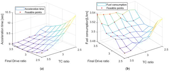
Figure 10.
Results on entire range of versus TC and FD and feasible points: (a) acceleration results; and (b) fuel consumption results.
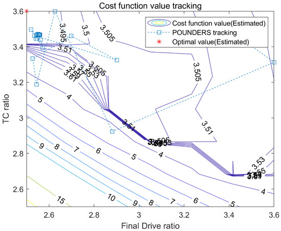
Figure 11.
Cost function value contour and parameter optimization history for FD and TC.
Table 6.
Acceleration performance for Case 3.
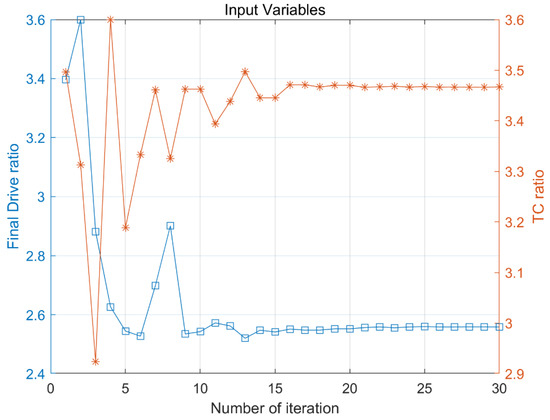
Figure 12.
Optimization results for the FD(blue, cube) and TC(orange, asterisk) ratios.
In the two parameter cases, the GB ratio has no correlation with acceleration performance, and the larger the TC or FD values, the better the acceleration performance. Because the maximum torque is the most important factor in acceleration performance from a standstill position, it is clear that, in general, the higher the gear ratio, the better the acceleration performance. However, if the gear ratio is too large, it may not reach 100 kph because of the maximum speed limit of the engine or motor. On the other hand, the correlation between fuel economy and parameters is not linear because of the nonlinearity of the engine and motor efficiency maps, and the fact that the objective is to minimize the fuel consumption of the two driving cycles, the UDDS and HWFET. However, all three cases showed results that converged close to the optimal point, and based on these results, we were finally able to conduct optimization of the three parameters.
We determined the parameter search range in Case 4, which runs the three-parameter optimizations and performed the following optimization. As shown in Table 7, all three parameters were set as optimization variables, and the proposed optimization process was performed in the same manner as in the previous cases.
Table 7.
Lower and upper ranges of Case 4 parameters.
Figure 13 shows how the parameter value changes during the optimization process. In a three-parameter optimization such as Case 4, the acceleration time, fuel consumption, and cost function value map for all areas is not shown because the computational load increases exponentially as the number of parameters increases.
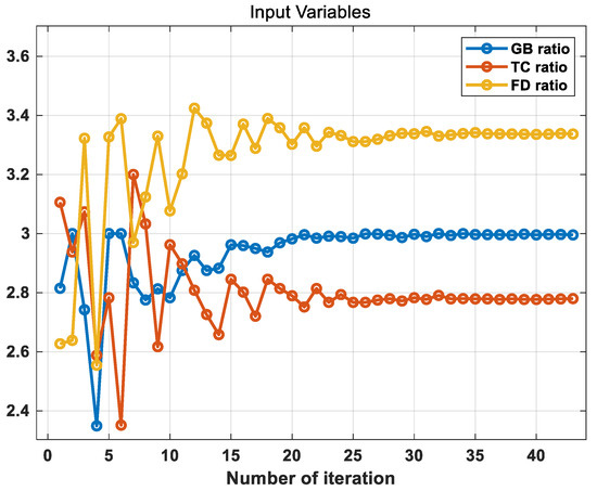
Figure 13.
Optimization results for the GB, FD and TC ratios.
Table 4 and Table 8 show the optimized parameter values and fuel consumption results for all cases, respectively. The fuel consumption is 3.493 L/100 km for combined cycle, which is an improvement compared to 3.527 L/100 km for the non-sized case. The optimized values are 2.995, 3.337 and 2.780 for the GB, TC and FD ratios, respectively.
Table 8.
Component-sizing results and acceleration performance for Case 4.
In this study, the fuel consumption results for three gear ratios of a power-split hybrid vehicle were minimized using the proposed sizing algorithm.
The vehicle specification of the non-sized case is the specification currently released on the market. The optimization result using the proposed sizing algorithm shows better results than that of the non-sized case. Although the proposed sizing algorithm uses an optimization algorithm, there is a limitation that it cannot guarantee global optimization. In addition, the parameters of the non-sized case, which is the base-line case, still use the specifications of the vehicle currently released on the market. This value has already been optimized to some extent by the carmaker, so there is not much room for optimization. For this reason, the result of Case 4, which optimizes three parameters, has higher fuel consumption than the result of Case 3, which optimizes two parameters. On the contrary, in the process of vehicle development, the near optimal value of each parameter can be obtained through the proposed algorithm.
5. Discussion and Conclusions
This paper proposes a component-sizing optimization process using a derivative-free optimization algorithm because of the high nonlinearity and complexity of vehicle powertrain systems. This process finds the component size set to minimize fuel consumption while satisfying dynamic requirements. Applying PMP as an optimal control for the energy management strategy ensures a fair comparison with respect to energy management for different component sizes. Although the algorithm does not guarantee finding the global optimal, it converges to a point that is quite close to the optimum point and shows good optimization performance. In addition, when using a brute-force method, as the number of design parameters increases, the number of cases to be considered increases exponentially, which requires a significant amount of time and effort. In contrast, using the proposed process to find the optimal component sizes can save researchers a significant amount of time and effort. As mentioned in the introduction, POUNDERS, a sizing algorithm, was developed for the black-box optimization problem, so it can be applied to all powertrain structures. It is also applicable to conventional vehicles [17]. In addition, it is possible to optimize not only the gear ratio, but also all parameters for which data can be input, such as engine or motor size. Thanks to this applicability of the algorithm, the methodology presented in this study can be used for almost all types of vehicle.
Author Contributions
Conceptualization, N.K. and J.J.; methodology, N.K.; software, N.K.; validation, N.K., J.J., R.V. and K.K.; resources, S.M. and H.Y.; data curation, N.K.; writing—original draft preparation, K.K.; writing—review and editing, N.K. and S.W.C.; visualization, K.K.; supervision, A.R. and S.W.C.; project administration, A.R.; funding acquisition, A.R. All authors have read and agreed to the published version of the manuscript.
Funding
The submitted manuscript has been created by UChicago Argonne, LLC, Operator of Argonne National Laboratory (“Argonne”). Argonne, a U.S. Department of Energy Office of Science laboratory, is operated under Contract No. DE-AC02-06CH11357. The U.S. Government retains for itself, and others acting on its behalf, a paid-up nonexclusive, irrevocable worldwide license in said article to reproduce, prepare derivative works, distribute copies to the public, and perform publicly and display publicly, by or on behalf of the Government. The Department of Energy will provide public access to these results of federally sponsored research in accordance with the DOE Public Access Plan. http://energy.gov/downloads/doe-public-accessplan (accessed on 10 April 2021). Additionally, this research was funded by Hyundai Motor Group.
Conflicts of Interest
The authors declare no conflict of interest.
Nomenclature
| Acronyms | Description |
| BEV | Battery Electric Vehicle |
| DP | Dynamic Programming |
| EMS | Energy Management strategy |
| FD | Final Drive gear |
| GB | Planetary gear |
| HEV | Hybrid Electric Vehicle |
| HWFET | Highway Fuel Economy Test |
| MG | Motor/Generator |
| PHEV | Plug-in Hybrid Electric Vehicle |
| PMP | Pontryagin’s Minimum Principle |
| POUDERS | Practical Optimization Using NO Derivatives for sums of Squares |
| TC | Motor reduction gear |
| THS system | Toyota Hybrid System |
| UDDS | Urban Dynamometer Driving Schedule |
| Sub-scripts | |
| 0 | Initial value |
| f | Final value |
| Symbols | Description |
| c | Constraint |
| Cd | Drag coefficient |
| h | Cost function |
| H | Hamiltonian |
| l | Lower limit |
| mf | Fuel consumption |
| p | Costate |
| Pb | Battery power |
| r | Design variable |
| s | Slack variable |
| SOC | State of charge |
| t | Time |
| u | Upper limit |
| µ | Penalty parameter |
| λ | Lagrangian multipliers |
References
- Kim, N.; Rousseau, A.; Rask, E. Parameter estimation for a lithium-ion battery from chassis dynamometer tests. IEEE Trans. Veh. Technol. 2016, 65, 4393–4400. [Google Scholar] [CrossRef]
- Zhang, X.; Peng, H.; Sun, J. A Near-Optimal Power Management Strategy for Rapid Component Sizing of Multimode Power Split Hybrid Vehicles. IEEE Trans. Control Syst. Technol. 2015, 23, 609–618. [Google Scholar] [CrossRef]
- Karbowski, D.; Kim, N.; Rousseau, A. Route-Based Online Energy Management of a PHEV and Sensitivity to Trip Prediction. In Proceedings of the 2014 IEEE Vehicle Power and Propulsion Conference, Coimbra, Portugal, 27–30 October 2014. [Google Scholar] [CrossRef]
- Bradley, T.H.; Frank, A.; Design, A. Demonstrations and Sustainability Impact Assessments for Plug-in Hybrid Electric Vehicles. Renew. Sustain. Energy Rev. 2009, 13, 115–128. [Google Scholar] [CrossRef]
- Samaras, C.; Meisterling, K. Life Cycle Assessment of Greenhouse Gas Emissions from Plug-in Hybrid Vehicles: Implications for Policy. Environ. Sci. Technol. 2008, 42, 3170–3176. [Google Scholar] [CrossRef] [PubMed]
- Zheng, C.H.; Kim, N.W.; Cha, S.W. Optimal Control in the Power Management of Fuel Cell Hybrid Vehicles. Int. J. Hydrog. Energy 2012, 37, 655–663. [Google Scholar] [CrossRef]
- Uzunoglu, M.; Alam, M.S. Dynamic Modeling, Design and Simulation of a PEM Fuel Cell/Ultra-Capacitor Hybrid System for Vehicular Applications. Energy Convers. Manag. 2007, 48, 1544–1553. [Google Scholar] [CrossRef]
- Lin, W.; Zheng, C. Energy management of a fuel cell/ultracapacitor hybrid power system using an adaptive optimal-control method. J. Power Sources 2011, 196, 3280–3289. [Google Scholar] [CrossRef]
- Wróblewski, P.; Drożdż, W.; Lewicki, W.; Dowejko, J. Total Cost of Ownership and Its Potential Consequences for the Development of the Hydrogen Fuel Cell Powered Vehicle Market in Poland. Energies 2021, 14, 2131. [Google Scholar] [CrossRef]
- Kim, N.; Moawad, A.; Vijayagopal, R.; Rousseau, A. Validation of sizing algorithm for several vehicle powertrains. In Proceedings of the 2016 FISITA World Automotive Congress, Busan, South Korea, 26–30 September 2016. [Google Scholar]
- Lee, H.; Sung, J.; Kang, C.; Park, Y.I.; Lim, W.; Cha, S.W. Design and analysis of new plug-in hybrid electric vehicle powertrain. In Proceedings of the FISITA World Automotive Congress, Busan, South Korea, 26–30 September 2016. [Google Scholar]
- Zhang, X.; Li, C.T.; Kum, D.; Peng, H. Prius + and Volt -: Configuration analysis of power-split hybrid vehicles with a single planetary gear. IEEE Trans. Veh. Technol. 2012, 61, 3544–3552. [Google Scholar] [CrossRef]
- Madanipour, V.; Montazeri-Gh, M.; Mahmoodi-k, M. Optimization of the component sizing for a plug-in hybrid electric vehicle using a genetic algorithm. Proc. Inst. Mech. Eng. Part D J. Automob. Eng. 2016, 230, 692–708. [Google Scholar] [CrossRef]
- Lee, D.; Kim, N.; Jeong, J.; Park, Y.; Cha, S.W. Component sizing and engine optimal operation line analysis for a plug-in hybrid electric transit bus. Intl. J. Autom. Technol. 2013, 14, 459–469. [Google Scholar] [CrossRef]
- Pourabdollah, M.; Murgovski, N.; Grauers, A.; Egardt, B. Optimal sizing of a parallel PHEV powertrain. IEEE Trans. Veh. Technol. 2013, 62, 2469–2480. [Google Scholar] [CrossRef]
- Sim, K.; Vijayagopal, R.; Kim, N.; Rousseau, A. Optimization of component sizing for a fuel cell-powered truck to minimize ownership cost. Energies 2019, 12, 1125. [Google Scholar] [CrossRef]
- Lee, H.; Cha, S.W.; Kim, N.; Jeong, J.; Vijayagopal, R.; Rousseau, A. Development of vehicle component sizing process using optimization algorithm. In Proceedings of the 2017 IEEE Vehicle Power and Propulsion Conference (VPPC), Belfort, France, 14–17 December 2017. [Google Scholar] [CrossRef]
- Furukawa, T.; Ibaraki, R.; Kimura, H.; Kondo, K.; Watanabe, M.; Mizutani, T.; Hattori, H.; Takasaki, A. Development of new hybrid transaxle for sub-compact-class vehicles. SAE Tech. Pap. 2012. [Google Scholar] [CrossRef]
- Ichikawa, S.; Takeuchi, H.; Fukuda, S.; Kinomura, S.; Tomita, Y.; Suzuki, Y.; Hirasawa, T. Development of new plug-in hybrid system for compact-class vehicle. SAE Int. J. Altern. Powertrains 2017, 6. [Google Scholar] [CrossRef]
- Suzuki, Y.; Nishimine, A.; Baba, S.; Miyasaka, K.; Tsuchida, M.; Endo, H.; Yamamura, N.; Miyazaki, T. Development of new plug-in hybrid transaxle for compact-class vehicles. SAE Tech. Pap. 2017. [Google Scholar] [CrossRef]
- Gopal, R.V.; Rousseau, A.P. System analysis using multiple expert tools. SAE Tech. Pap. 2011. [Google Scholar] [CrossRef]
- Autonomie. Available online: http://www.autonomie.net/ (accessed on 27 May 2021).
- Jeong, J.; Kim, N.; Stutenberg, K.; Rousseau, A. Analysis and model validation of the Toyota Prius Prime. SAE Tech. Pap. 2019, 1–9. [Google Scholar] [CrossRef]
- Kim, N.; Cha, S.; Peng, H. Optimal control of hybrid electric vehicles based on Pontryagin’s Minimum Principle. IEEE Trans. Control Syst. Technol. 2011, 19, 1279–1287. [Google Scholar] [CrossRef]
- Kirk, D.E. Optimal Control Theory. An Introduction; Prentice Hall: Englewood Cliffs, NJ, USA, 1970. [Google Scholar]
- Wild, S.M. Solving Derivative-Free Nonlinear Least Squares Problems with POUNDERS; Argonne National Laboratory: Lemont, IL, USA, 2014. [Google Scholar]
- U.S. Environmental Protection Agency, U.S. Department of Energy. Model Year 2020 Fuel Economy Guide; DOE/EE-1982; EERE Information Center: Gaithersburg, MD, USA, 2020.
- Fuel Economy Home Page. Gasoline Vehicles: Learn More about the Label. Available online: https://www.fueleconomy.gov/feg/label/learn-more-gasoline-label.shtml (accessed on 21 March 2020).
Publisher’s Note: MDPI stays neutral with regard to jurisdictional claims in published maps and institutional affiliations. |
© 2021 by the authors. Licensee MDPI, Basel, Switzerland. This article is an open access article distributed under the terms and conditions of the Creative Commons Attribution (CC BY) license (https://creativecommons.org/licenses/by/4.0/).