Article

Research and Development of the Oxy-Fuel Combustion Power Cycles with CO2 Recirculation

1
Department of Innovative Technologies of High-Tech Industries, National Research University “Moscow Power Engineering Institute”, 111250 Moscow, Russia
2
Department of Thermal Power Plants, National Research University “Moscow Power Engineering Institute”, 111250 Moscow, Russia
*
Author to whom correspondence should be addressed.
Energies 2021, 14(10), 2927; https://doi.org/10.3390/en14102927
Submission received: 16 March 2021 / Revised: 12 May 2021 / Accepted: 14 May 2021 / Published: 18 May 2021
(This article belongs to the Special Issue Energy Complex System Simulation, Design, and Optimisation)

Abstract

:
The transition to oxy-fuel combustion power cycles is a prospective way to decrease carbon dioxide emissions into the atmosphere from the energy sector. To identify which technology has the highest efficiency and the lowest emission level, a thermodynamic analysis of the semiclosed oxy-fuel combustion combined cycle (SCOC-CC), the E-MATIANT cycle, and the Allam cycle was carried out. The modeling methodology has been described in detail, including the approaches to defining the working fluid properties, the mathematical models of the air separation unit, and the cooled gas turbine cycles’ calculation algorithms. The gas turbine inlet parameters were optimized using the developed modeling methodology for the three oxy-fuel combustion power cycles with CO2 recirculation in the inlet temperature at a range of 1000 to 1700 °C. The effect of the coolant flow precooling was evaluated. It was found that a decrease in the coolant temperature could lead to an increase of the net efficiency up to 3.2% for the SCOC-CC cycle and up to 0.8% for the E-MATIANT cycle. The final comparison showed that the Allam cycle’s net efficiency is 5.6% higher compared to the SCOC-CC cycle, and 11.5% higher compared with the E-MATIANT cycle.

1. Introduction

The International Energy Agency expects a 30% increase in power consumption during 2016–2040 [1]. The annular combustion of hydrocarbons will also grow, which increases the toxic and greenhouse gases’ atmospheric emissions. The anthropogenic pressure aggravates the problem of the 21st century’s local and worldwide stable development.
The power production industry produces a remarkable amount of harmful emissions [2], so the mitigation of power facility emissions is a topical direction. Today, thermal power plants successfully reduce nitrogen and sulfur oxide emissions [3,4,5,6,7]. Organic fuel combustion produces huge amounts of carbon dioxide, and its emissions still are a difficult problem [8,9]. Widely known carbon dioxide capturing technology considerably increases the power production expenses [10,11,12]. The creation of environmentally friendly and financially efficient large power facilities is a valid problem. This is emphasized by the introduction of some international agreements, especially the Paris Climate Agreement, which has been signed by nearly 200 countries.
Oxy-fuel combustion technology is a promising method for harmful emission mitigation in the power production industry [13,14,15]. Unlike traditional technology, oxy-fuel combustion power cycles create less atmospheric harm through the application of a closed gas turbine cycle, oxy-fuel combustion, and carbon dioxide capture and storage. The high efficiency of these cycles is due to the thermodynamic separation of the working fluid that allows for the highly efficient separation of carbon dioxide from the water steam through steam condensing in a cooler-separator.
The first modifications of these power facilities appeared at the end of the 20th century, and now, the USA, Japan, and EU countries are actively developing this direction. Research studies are being carried out, test facilities are being built, and foundations for the zero emission pilot facilities are being create using grant funding, active “green technology” backing, and through the creation of legislation bases. Large power corporations cooperate in a buildup of demonstration facilities with power outputs of up to 50 MW [16].
The widely known oxy-fuel combustion power cycles, such as the semiclosed oxy-fuel combustion combined cycle, the E-MATIANT cycle, the Allam cycle, the Graz cycle, AZEP, and ZEITMOP [17], may be classified as such. The semiclosed oxy-fuel combustion combined cycle (SCOC-CC), the E-MATIANT, and the Allam cycles involve carbon dioxide recirculation, which reduces the combustion temperature. In these cycles, the main operating component is carbon dioxide. In the Graz and the “water” cycles, the temperature is reduced with water, which is the main operating component. The AZEP and ZEITMOP cycles use high temperature membranes integrated into the cycle heat flow circuit.
Numerous papers disclose the results of research and development of methods for increasing efficiency of the existing oxy-fuel combustion power cycles. In particular, a possible way to increase efficiency of the SCOC-CC cycle is an application of the additional recuperator in the heat recovery system [18]. The net efficiency of the R-SCOC-CC is higher compared to SCOC-CC by 0.6 and 1.3% in the F- and H-class gas turbines cases, respectively. Another way to increase the SCOC-CC efficiency is an application of liquid oxygen pump supply of oxidizer to the combustion chamber [19]. Using this method cycle efficiency could be increased by 3%.
In turn, the modified layout of the MATIANT cycle is proposed in [20]. The scheme includes three changes to achieve a more balanced thermal match of the recuperator and to lower the compression power: the reheating process is eliminated, stream split and recompression are added, and the compressor is replaced by a seven-stage one. The optimized efficiency of the new cycle can reach 45.3%, which is 0.35% lower than that of the MATIANT cycle. However, an advantage is the layout’s simplicity.
One of the latest modifications of the Allam cycle is the Allam-Z cycle proposed in [21]. The main modifications are that all the working media are pumped to high pressure by pumps instead of compressors, the cold energy of both liquid oxygen and liquefied natural gas is used for degrading the cooling water for carbon dioxide liquefaction, and a set of regenerative heat exchangers are arranged for turbine exhaust heat recovery.
The selection of the most promising power production technology is an integrated problem that involves numerous factors, including efficiency, environmental harm, and production expenses. The influencing factors must be compared with compatible input data and common simulation methods. Most of the available efficiency assessments presented in the literature involve different simulation approaches. The difference may be seen in assessments of the working fluid thermodynamic parameters, the oxygen production power consumption, the cooled gas turbine model, and the flow analysis algorithm. When modeling oxy-fuel combustion cycles, special attention should be paid to the estimation of gas turbine cooling losses because coolant massflow is significant due to the working fluid and cooling agent thermophysical parameters. The development of methods allowing to decrease carbon dioxide gas turbine coolant flow is of special importance.
This investigation is devoted to an efficiency increase of the existing oxy-fuel combustion cycles with the carbon dioxide working fluid (the SCOC-CC cycle, the E-MATIANT cycle, and the Allam cycle). This problem’s solution includes the following steps. The first step includes the development of the analysis and simulation methods for the oxy-fuel combustion power cycles. The second step consists of the structural and parametric optimization devoted to the cycles’ efficiency improvement and environmental risk reduction. The third step is a comparison of the efficiency, environmental friendliness, and production expenses of the most promising oxy-fuel combustion power cycles and the combined cycle with carbon dioxide capture.

2. Basic Schemes and Initial Parameters for Simulation of the Oxy-Fuel Combustion Power Cycles

The first investigation object is the SCOC-CC cycle (Figure 1), first published in 1992 by O. Bolland and S. Saether [14]. It differs from the combined cycle facility prototype with the increase of carbon dioxide partial pressure by the oxy-fuel combustion and the recirculation into the combustor of a large part of flue gas from the heat recovery steam generator. This combination reduces the power consumption for the carbon dioxide separation.
The second investigation object is the E-MATIANT cycle (Figure 2), which is a prospective modification of the MATIANT proposed in 1997 by Mathieu and Yantovsky [22]. It differs from the SCOC-CC cycle in that the compressor and turbine consist of a few cells, with the intermediate cooling for the compressor and the working fluid superheating for the turbine. Instead of the heat recovery steam generator, the exhaust gas is cooled in a regenerative heat exchanger. The intermediate cooling and superheating improve the power production efficiency.
The last investigation object is the Allam cycle (Figure 3). This cycle is free from the two main shortages of the oxy-fuel combustion power plants, which are the large losses of carbon dioxide compression before its storage and the irreversible losses of the hot air low potential heat. R. Allam patented this technology in 2010 [23]. The specific features of this cycle are the high initial and final pressures and the multiflow regenerator.
Table 1 summarizes the main input data used for the computer simulation of three oxy-fuel combustion power plants.

3. Methodology

3.1. Mathematical Model and Calculation Algorithm for the Investigation of the Oxy-Fuel Combustion Power Cycle

The computer simulation models of oxy-fuel combustion power plants (Figure 4) consist of the following three main blocks connected with flow and energy couplings:
  • An air separation unit that produces high purity oxygen (mathematical model of ASU was developed using MATLAB software [24]).
  • A semiclosed gas turbine cycle (SCGTC) producing electricity (mathematical models of cycles were developed using AspenONE [25] and MATLAB software).
  • A multistaged intercooled compressor that compresses carbon dioxide before storage (mathematical model of ICC was developed using AspenONE software).
Figure 5 illustrates the computer simulation algorithm for the SCGTC cycle. The first step is the cycle thermodynamic calculation without gas turbine cooling losses using mathematical models implemented with AspenONE software. Next, the thermodynamic parameter values in the nodes of schemes are used for the gas turbine 1D analysis that determines the turbine flowpath dimensions. The cooled gas turbine model was realized using MATLAB software. The influences of the turbine performance, the working fluid, and coolant thermophysical parameters are taken into account in the coolant massflow and grid cooling loss calculations. The third simulation step is the cycle thermodynamic calculation including the gas turbine cooling losses.
The assessment method for the working fluid thermodynamic parameters remarkably influences the accuracy of the analysis results. The database NIST REFPROP provides the smallest errors of CO2 parameters for pressures of 0.1–30 MPa and temperatures of 30–1400 °C, which is confirmed by the comparison of the available gas state equations [26]. This database was used for the thermodynamic calculations.

3.2. Mathematical Model of the Air Separation Unit

A remarkable part of the cycle internal power consumption lies in the oxidizer production. Its amount is determined by the air separation unit type, the massflow GO2 (kg/s) end, and the oxygen purity CO2 (%).
A 300 MW oxy-fuel combustion power facility requires high purity O2, which may be supplied by a high-pressure cryogenic air separation unit (ASU) with two-stage rectification [27,28,29]. The statistical analysis [30] provides two correlation functions for the O2 with a purity of 85–99%, which describe the oxygen production power consumption and the heat supplied by the compressed air.
The ASU power consumption NeASU (kW) may be calculated as follows:
NeASU = GO2 · eASU = GO2 · [3.45 · (CO2)2 − 591 · CO2 + 26,100],
where eASU is the specific ASU power, kW/(kg/s).
The low potential heat QASU (MW) carried by the ASU exit airflow may be utilized in the multiflow regenerator, and is calculated as follows:
QASU = 1.027 · G.
The correlation functions mentioned above were used for the simulation of the oxy-fuel combustion power cycles.

3.3. Mathematical Model of the Cooled Carbon Dioxide Gas Turbine

Oxy-fuel combustion power cycles reach a high efficiency at working fluid initial temperatures above 1000 °C. The maximal temperature for the available heat resistance alloys used for the gas turbine hot parts is about 870 °C [31], so the carbon dioxide turbine reliable long term operation requires cooling of its flowpath elements.
The thermodynamic studies [32] show that the gas turbine cooling losses remarkably hurt the cycle thermal efficiency. An accurate assessment of these losses involves the influence of the turbine specific structural features and the new heat carrier thermophysical parameters. Therefore the thermodynamic cycle analysis requires a carbon dioxide cooled turbine simulation model that allows the coolant flow to split between the high temperature grids.
The developed turbine performance analysis algorithm involves the influence of the heat carrier and flowpath parameters on the coolant massflow (Figure 6).
The first step of the algorithm is to input the following data:
  • Turbine inlet/exit thermodynamic parameters.
  • The noncooled turbine flowpath specific internal efficiency ηoi.
  • Main fluid massflow at the turbine inlet D0 or the turbine electric power Ne.
Then, the root diameter configuration, reaction degree, velocity ratio, and turbine rotation speed are assumed. This makes the base for the 1D flowpath calculation.
If the last stage blade length lz or the turbine exit Mach number Mz are above the acceptable values of lmax and Mmax, or if the first stage blade length l1 is shorter than acceptable lmin, then the new root diameter and the turbine number of stages are input. Otherwise, the 1D noncooled flowpath calculation is considered as completed.
The next step is the input of following parameters for the evaluation of the airfoil cooling efficiency:
  • Selection of the cooling system scheme.
  • Selection of the cooling system type, open or closed.
  • Maximal acceptable blade surface temperature.
The cooling system type considerably influences the turbine performance. In the open scheme, all of the coolant flow enters the flowpath. This type is used in convective and film cooling systems, and its advantage is its simple flow scheme. In the closed scheme, the coolant circulates in the cooling flow circuit. This type is used only for convective cooling, and its advantage is the absence of losses caused by the main and cooling flows mixing. In closed systems, the convective cooling principle remarkably limits the cooling capability, and the heat taken by the coolant should be utilized in a special heat exchanger. Thus, the cycle simulation involved the open cooling type, where the coolant and working fluid mix downstream every airfoil row.
After the coolant flows are determined, the flow expansion is recalculated with the main and coolant flow mixing taken into account. Then, the internal specific flowpath efficiency is calculated. Changes in the high temperature stage efficiency are combined with the thermodynamic parameter deviation, so it is necessary to recalculate the cooling massflow and the expansion process. This procedure is repeated while the thermodynamic parameters deviation occurs. When the thermodynamic parameters become constant (T1.i+1 = T1.i), the simulation process may be completed by the calculation of the energy parameters in the cooled and noncooled compartments.
The described algorithm worked in the turbine parametric studies. The studies’ results are functions of the coolant flow distribution among the high temperature stages, related to key parameters such as the initial temperature and pressure, coolant temperature at the cooling channels inlet, and acceptable metal temperature (here, a temperature of 870 °C was assumed). Table 2 presents the turbine parameters used in the simulation according to the authors of [33].
The following equation describes the total coolant massflow Ψ (%):
Ψ = 0.545 · (2.27 + 8.57 · 10−9 · T03 − 0.138 · P0) · e0.003 · Tcool.
This equation is applied within the limits of the following variables: initial working fluid temperature and pressure 1100 °C < T0 < 1500 °C and 10 MPa < P0 < 40 MPa, respectively, and the coolant temperature at the inlet of the blade channels of 100 °C < Tcool < 400 °C.
The following equation describes the coolant massflow distribution between the cooled stages:
Ψj = Ψ/100 · (5.58 + 1.05 · j − 0.0145 · T0)/(1 − 0.00489 · j − 0.00131 · T0).
Equation (4) is applied for a number of stages below 5 and airfoil row number j from 1 to 10, and the coolant massflow for the row j is Ψj (%).
The described algorithm and models were used for the thermodynamic studies of three oxy-fuel combustion power cycles with CO2 recirculation, namely: the SCOC-CC, the E-MATIANT cycle, and the Allam cycle.

4. Results and Discussion

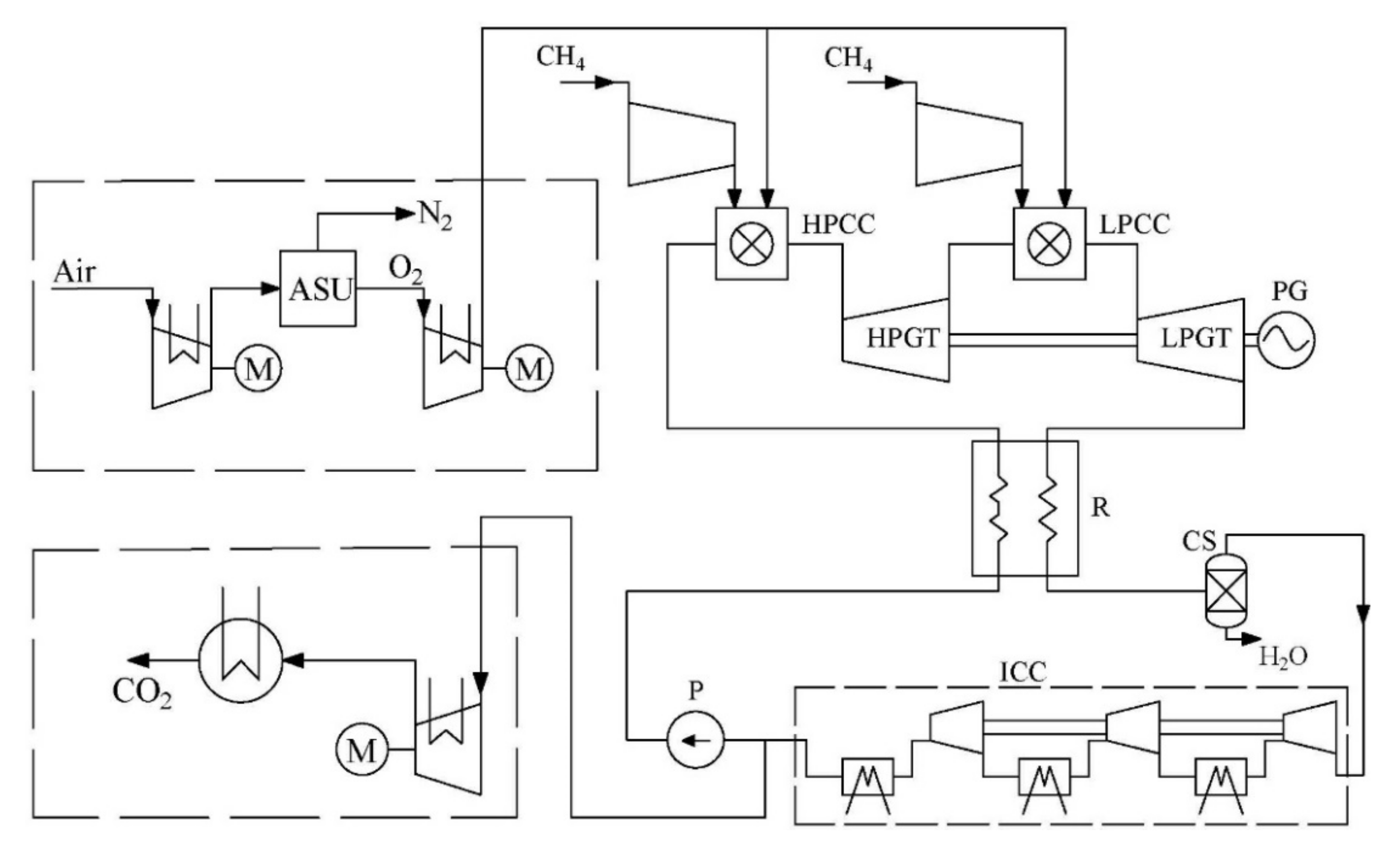
4.1. Structural and Parametric Optimization of the Semiclosed Oxy-Fuel Combustion Combined Cycle

The parametric optimization of the SCOC-CC cycle shows that when the initial fluid temperature increased from 1100 to 1700 °C, the optimal initial pressure, the coolant massflow, and the net efficiency grew from 2 to 7 MPa, from 8.1 to 36%, and from 41.0 to 47.7%, respectively (Figure 7). The fluid heat capacity in the compressor of the SCOC-CC was higher than in the compressor of the combined cycle. In turn, the fluid heat capacity in the gas turbine of the SCOC-CC was lower than in the gas turbine of the combined cycle. Therefore, the SCOC-CC optimal initial pressure was higher. Furthermore, the large SCOC-CC cooling flow causes considerable efficiency losses.
The preliminary cooling of the coolant flow may improve the SCOC-CC thermal efficiency (Figure 8 and Figure 9) [34]. Deep coolant cooling down to 150–250 °C may take place in a surface heat exchanger (SHE; Figure 8). The heat release source may be a part of the steam turbine condensate flow, and the net efficiency improvement may be up to 3.2%. On the contrary, when the coolant cooling to a temperature above 250 °C is smaller, it is reasonable to use the water injection into the coolant flow. The water may be taken from the gas cycle cooler-separator (Figure 9). This scheme improves the net efficiency up to 1.5%.
These schemes are free from the water production expenses, which is an advantage. It should be noted that preliminary cooling of the coolant flow may also improve the R-SCOC-CC efficiency [18]. However, the increase in efficiency will be lower compared to SCOC-CC due to lower values of the compressor outlet pressure causing the moderate temperature of the coolant.

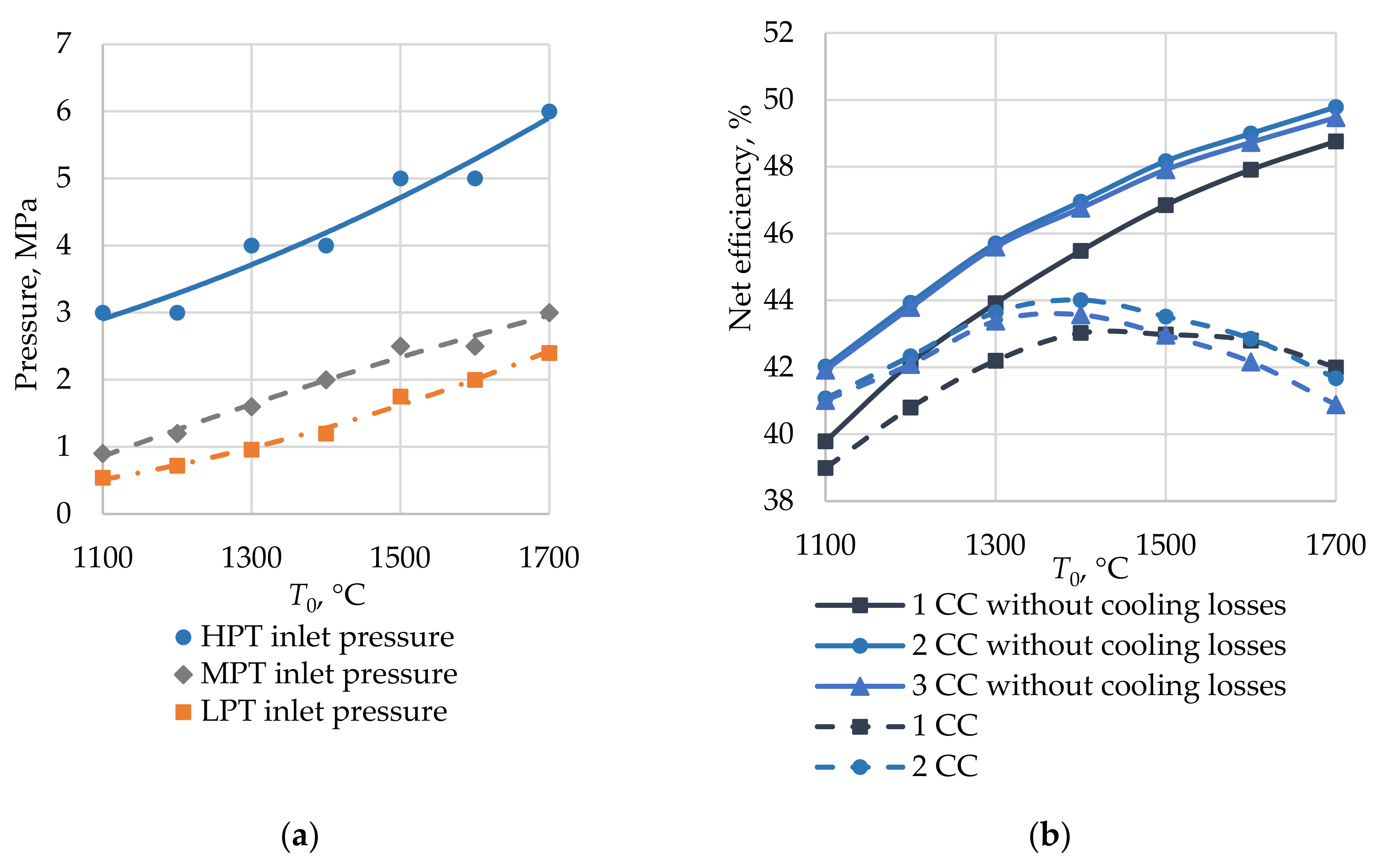
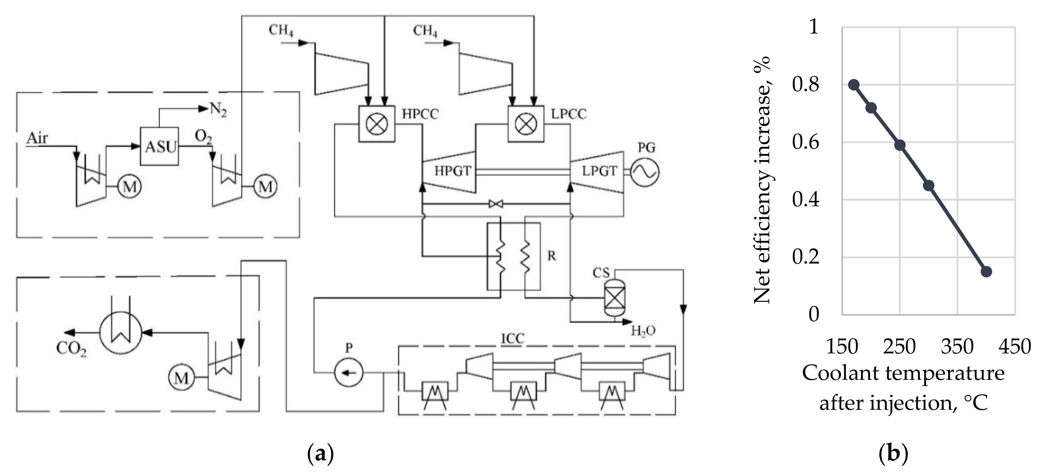
4.2. Structural and Parametric Optimization of the E-MATIANT Cycle

The Е-МАТIАNТ cycle optimization involved versions with one, two, and three combustors. The analysis determined the optimal initial and overheating pressures.
Figure 10 shows the influences of the initial parameters and the number of overheating stages in combustors upon the E-MATIANT cycle thermal efficiency. The E-MATIANT cycle with three combustors at initial temperatures of 1100–1700 °C has optimal inlet pressures of 3–6 MPa in an HPT, 0.9–3.0 MPa in an intermediate pressure turbine (IPT), and 0.5–2.4 MPa in an LPT (Figure 10a). Figure 10b shows a remarkable efficiency reduction caused by turbine cooling. At a temperature of 1700 °C, the net efficiency of the cycle with three combustors dropped down by 8.6%.
When the initial parameters grow, the turbine exhaust temperature also grows (Figure 11a). This temperature should not be above 750 °C because of the regenerator material temperature limit of 800 °C (the heat resistant steels XH35BTJu or 15X12BHMF are considered). Figure 11b shows the E-MATIANT cycle net efficiency calculated with the cooling losses and the regenerator inlet temperature limit.
The E-MATIANT cycle parametric optimization shows that the maximal net efficiency of 44.0% is reached for the case with two combustors, initial parameters of 1400 °C and 4 MPa, and a total coolant massflow and temperature of 40.3% and 400 °C, respectively. Here, the coolant source is the heated flow at the regenerator exit.
The intermediate cooling and overheating improve the cycle thermal efficiency, but the flowpath mean temperature causes remarkable cooling losses. Thus, the E-MATIANT cycle has a lower efficiency than the SCOC-CC cycle. Therefore, coolant precooling may be a possible method for efficiency improvement.
The coolant temperature had a reduction below 400 °C from the earlier coolant bleeding from the regenerator, but this caused an efficiency reduction because of higher losses in the cold source. The steam compartment could utilize the low potential heat of the coolant. These losses, together with the steam turbine unit absence, reduced the E-MATIANT cycle efficiency with the precooling in an intermediate surface heat exchanger.
The cooling flow may be lower without the efficiency reduction using an injection into the coolant flow of the water taken from the cooler-separator (Figure 12a). It is reasonable to inject water into the LPT coolant flow. If water is injected into the HPT cooling flow, the high initial pressure may cause the water steam to condense. The preliminary analysis shows that the water bleeding from the cooler-separator and its injection into the LPT cooling flow may increase the E-MATIANT cycle net efficiency by 0.8% (Figure 12b). The injection part will be 2.3–2.7% of the LPT inlet massflow.
The water injection could also be applied for IPT of the improved MATIANT cycle with stream split and recompression described in [20]. The source of the coolant flow in this case could be the HPT exhaust temperature of which is a bit below 400 °C.

4.3. Parametric Optimization of the Allam Cycle

The simulation results show the Allam cycle maximal net efficiency of 56.5% is reached at the following parameters:
  • Initial temperature of 1083 °C
  • Initial pressure of 30 MPa
  • Gas turbine exit pressure of 3 MPa
  • Coolant temperature of 200 °C
  • Coolant specific massflow of 7.7%
The production and compression of the oxygen supplied to the combustor and the carbon dioxide storage reduced the net efficiency by 7.2 and 0.4%, respectively (Figure 13). The low energy consumption on CO2 storage at 10 MPa is due to the cycle minimal pressure of 3 MPa.
Figure 14 shows the Allam cycle net efficiency vs. gas turbine exit pressure, coolant, and water temperatures at the initial parameters of 1083 °C and 30 MPa.
The coolant optimal temperature may be explained by the following. A change in the coolant temperature is related not only to its massflow change and the concerned cooling losses but also to the amount of heat utilized in the regenerator. The last factor crucially influences the cycle efficiency. At a coolant temperature of 200 °C, the regenerator transfers the maximal amount of heat.
The temperature of the cooling water supplied to the cooler-separators remarkably influences the Allam cycle’s efficiency. The simulation results in Figure 14c show a 2.1% cycle efficiency increase at a water temperature reduction of 10 °C. A cooling water temperature reduction below 20 °C is not desirable because of the risk related to the liquid phase formation in the multistage compressor flowpath.
The net efficiency deviation from its maximal value of 56.5% occurs at the initial pressure within the 25–30 MPa range, initial temperature of 1025–1210 °C, gas turbine exhaust pressure of 2.0–3.5 MPa, and coolant temperature of 100–300 °C. Therefore, the Allam cycle power facility design should stay within the values of these key parameters. An exit from the range of these parameters will cause a remarkable efficiency reduction, which is also partially supported by the research results described in [35].
Promising areas for further efficiency improvement of the Allam cycle are the transition to the Allam-Z cycle by the elimination of compressors [21] and integration of the additional low temperature cycles for utilization of the various low-grade heat sources.

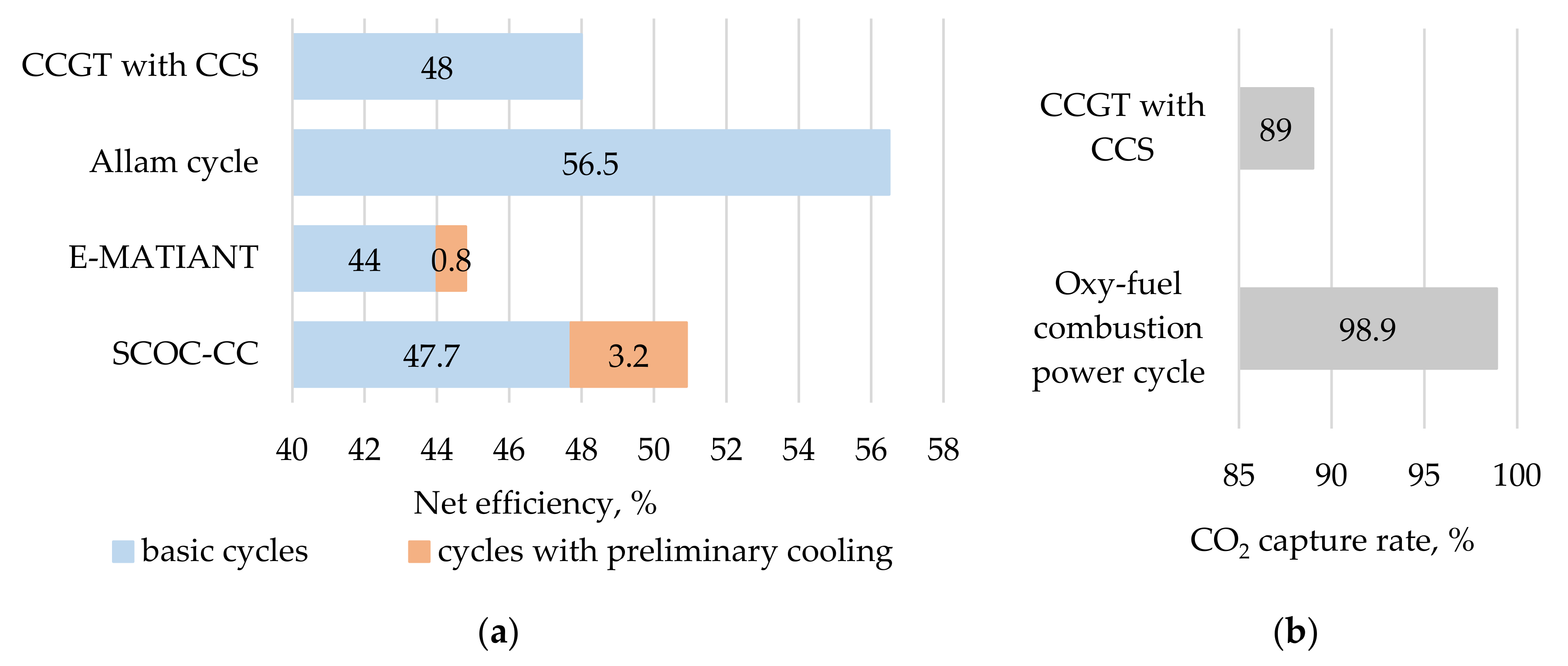
4.4. Oxy-Fuel and Combined Cycle with CO2 Storage Facilities Parameters Comparison

Parametric optimization of the oxy-fuel combustion power cycles with carbon dioxide working fluid provides the following dependencies of performance on the cycle initial and final parameters:
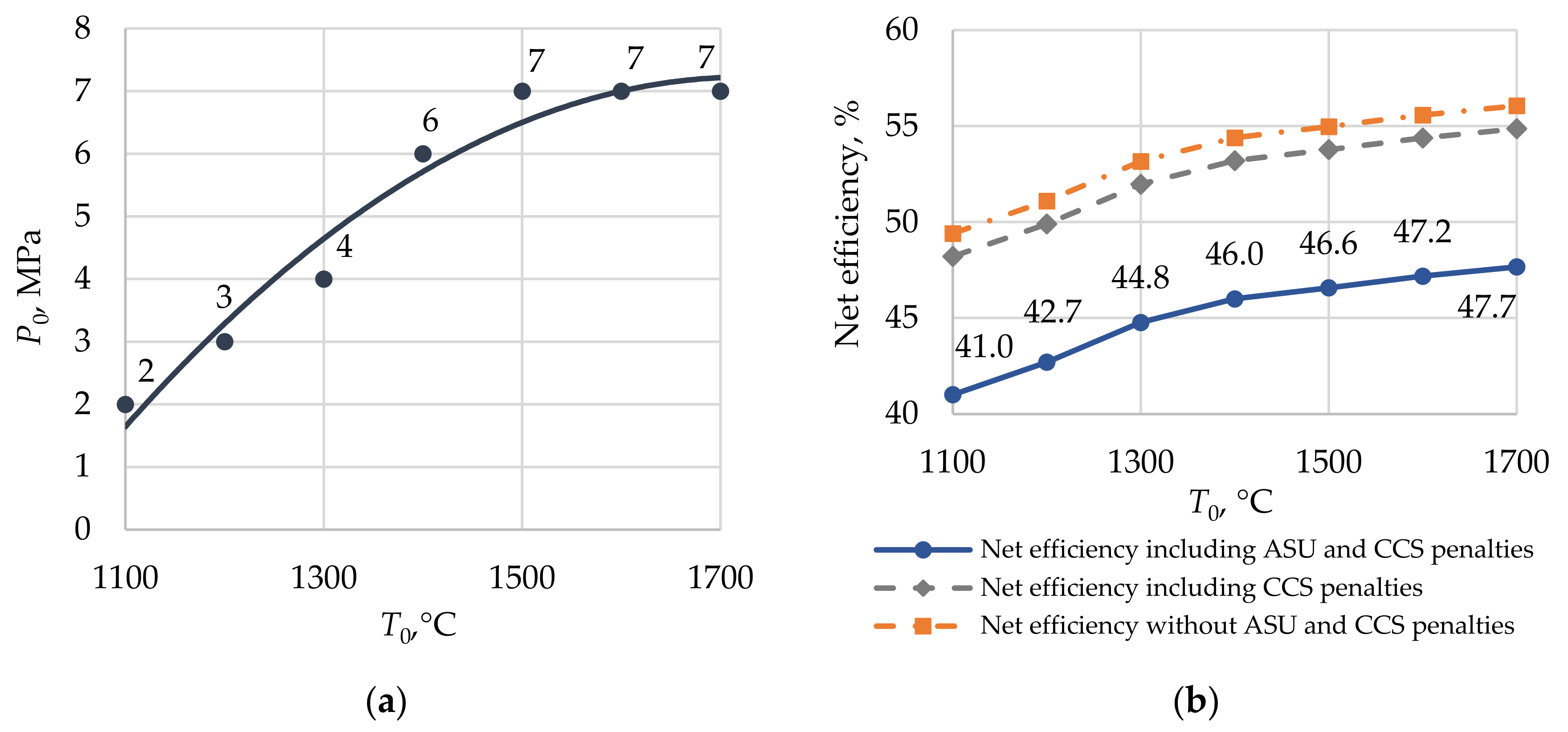
  • An increase of the SCOC-CC initial temperature from 1100 to 1700 °C causes the optimal pressure to increase from 2 to 7 MPa, the coolant massflow to increase from 8.1 to 36%, and results in the net efficiency to increase from 41.0 to 47.7%.
  • An increase of the E-MATIANT cycle initial temperature from 1100 to 1400 °C causes the optimal pressure increase from 3 to 4 MPa, the coolant massflow to increase from 14.5 to 40.3%, and causes the results in the net efficiency to increase from 41.1 to 44.0%.
  • An increase of the Allam cycle initial temperature from 1000 to 1100 °C causes the optimal pressure increase from 20 to 31 MPa, coolant massflow increase from 3.9 to 8.5%, and results in the net efficiency increase from 54.6 to 56.3%.
The following combinations of parameters provide the maximal net efficiency of oxy-fuel combustion power cycles with CO2 working fluid:
  • SCOC-CC working fluid initial parameters of 1700 °C/7 MPa.
  • E-MATIANT cycle working fluid parameters at high and low pressure turbine inlets of 1400 °C/4/2 MPa, and the temperature of the working fluid bleeding from the regenerator for the turbine cooling of 400 °C.
  • The Allam cycle working fluid initial parameters of 1083 °C/30 MPa, the turbine exhaust pressure of 3 MPa, and the temperature of working fluid bleeding from the regenerator for the turbine cooling of 200 °C.
The following technical solutions improve the efficiency of the oxy-fuel combustion power cycles with carbon dioxide working fluid:
  • SCOC-CC with cooling in the surface heat exchanger, where the cooling agent is a part of the steam turbine condensate and improves the net efficiency by 3.2%, which is reasonable to apply for the coolant to cool down to 150–250 °C.
  • SCOC-CC with cooling by the water injection: the water is bled from the gas cycle cooler-separator and is injected into the coolant flow to reduce its temperature down to 250 °C. The net efficiency increase is up to 1.5%.
  • The E-MATIANT cycle with the low pressure turbine coolant taken from the regenerator and cooled by injection of the water bleed from the cooler-separator. The net efficiency grows by 0.8%.
At optimal thermodynamic parameters, the Allam cycle net efficiency is 8.8% higher than the SCOC-CC one, and 12.5% higher than the E-MATIANT one (Figure 15a). Besides this, the Allam cycle has a remarkably higher operating pressure and lower initial temperatures (Figure 15b), which provides a minimal turbine cooling massflow (Figure 15c).
Thus, it is possible to conclude that the Allam cycle has a higher efficiency than the competitive oxy-fuel cycles because of a combination of the following thermodynamic features:
  • The working fluid is compressed near the CO2 saturation line, which reduces the compressor drive power consumption.
  • The useful utilization in the regenerator of low potential heat reduces heat losses in the cold source.
  • Minimal gas turbine coolant flow caused by the moderate initial temperature.
  • Minimal power consumption for the compression of the separated content due to the high final pressure.
The oxy-fuel combustion power cycles have obvious advantages against the combined cycle of CO2 separation from flue gas. The Allam cycle net efficiency is 8.5% higher than the combined cycle efficiency (Figure 16a) at conditions of CO2 capturing at 98.9% for the oxy-fuel combustion power cycle and 89% for the combined cycle (Figure 16b).
The cost parameters of the environmentally safest oxy-fuel Allam cycle are compared with the combined cycle with CO2 storage for the power facility nominal power annual operation of 6000 h for 30 years and CO2 storage at 10 MPa. The Allam cycle installed power cost facility was 46% lower, or $1398/kW against $2423/kW. This difference is caused by the absence of expensive equipment for CO2 separation from flue gas with a high nitrogen content and with steam turbine elements. More than that, the price of the Allam cycle CO2 storage is 5.5% lower due to the smaller mass of produced CO2, or 343 against 413 G/(kW·hr), and utilized CO2 339 against 367 G/(kW·hr).

5. Conclusions

  • The developed set of algorithms, methods, and recommendations for oxy-fuel combustion power cycle simulation allow for the calculation of thermal efficiency, including cooling losses in a high temperature turbine, and the power and fluid flow transition between the power production compartment and the air separation unit.
  • Structural and parametric optimization of the oxy-fuel combustion power cycles with carbon dioxide working fluid was carried out for the initial temperature ranges from 1100 to 1700 °C. An influence of the initial temperature and pressure on cycles’ performance was estimated. Optimal parameter combinations providing maximum net efficiency were identified. Significant values of the coolant massflow were identified for the SCOC-CC and E-MATIANT cycles working at initial temperatures higher than 1200 °C.
  • Several new technical solutions improving oxy-fuel combustion power cycles’ efficiency were suggested consisting in preliminary cooling of the coolant flow in the surface heat exchanger and by the water injection. The calculation results confirmed the possibility to increase cycles’ efficiency by 0.8–3.2% by reducing gas turbine cooling losses.
  • The analysis results show that the Allam cycle is one of the most effective oxy-fuel technologies. The cycle net efficiency is 8.5% higher than the combined cycle with carbon dioxide capturing, the carbon dioxide emission is 11–12 times smaller, and the installed power cost is 46% lower. However, the Allam cycle design efficiency remarkably depends on the simulation conditions of a multiflow regenerative heat exchanger. The efficiency estimations disclosed here may be applied when the regenerator is considered as a united heat exchanging device. In further studies, it is reasonable to design, in detail, the multiflow heat exchanging system, and to re-evaluate the thermal efficiency of the prospective oxy-fuel combustion power cycle operating with supercritical carbon dioxide.

Author Contributions

Conceptualization, A.R. and N.R.; methodology, A.R. and V.K.; software, V.K. and I.K.; validation, V.K. and I.K.; formal analysis, O.Z.; investigation, A.R., V.K., and I.K.; resources, O.Z.; data curation, I.K.; writing (original draft preparation), V.K.; writing (review and editing), A.R. and O.Z.; visualization, I.K.; supervision, A.R. and N.R.; project administration, A.R.; funding acquisition, O.Z. All authors have read and agreed to the published version of the manuscript.

Funding

This study conducted by the Moscow Power Engineering Institute was financially supported by the Ministry of Science and Higher Education of the Russian Federation (project no. FSWF-2020-0020).

Institutional Review Board Statement

Not applicable.

Informed Consent Statement

Not applicable.

Data Availability Statement

Not applicable.

Conflicts of Interest

The authors declare no conflict of interest.

References

  1. World Energy Outlook 2018; IEA: Paris, France, 2018.
  2. Nejat, P.; Jomehzadeh, F.; Taheri, M.M.; Gohari, M.; Majid, M.Z.A. A global review of energy consumption, CO2 emissions and policy in the residential sector (with an overview of the top ten CO2 emitting countries). Renew. Sust. Energy Rev. 2015, 43, 843–862. [Google Scholar] [CrossRef]
  3. Dutka, M.; Ditaranto, M.; Løvås, T. Application of a central composite design for the study of NOx emission performance of a low NOx burner. Energies 2015, 8, 3606–3627. [Google Scholar] [CrossRef] [Green Version]
  4. Volchyn, I.A.; Haponych, L.S. Estimate of the sulfur dioxide concentration at thermal power plants fired by Donetsk coal. Power Technol. Eng. 2014, 48, 218–221. [Google Scholar] [CrossRef]
  5. Jo, H.; Kang, K.; Park, J.; Ryu, C.; Ahn, H.; Go, Y. Optimization of air distribution to reduce NOx emission and unburned carbon for the retrofit of a 500 MWe tangential-firing coal boiler. Energies 2019, 12, 3281. [Google Scholar] [CrossRef] [Green Version]
  6. Loo, L.; Konist, A.; Neshumayev, D.; Pihu, T.; Maaten, B.; Siirde, A. Ash and flue gas from oil shale oxy-fuel circulating fluidized bed combustion. Energies 2018, 11, 1218. [Google Scholar] [CrossRef] [Green Version]
  7. Fuller, A.; Maier, J.; Karampinis, E.; Kalivodova, J.; Grammelis, P.; Kakaras, E.; Scheffknecht, G. Fly ash formation and characteristics from (co-) combustion of an herbaceous biomass and a Greek lignite (low-rank coal) in a pulverized fuel pilot-scale test facility. Energies 2018, 11, 1581. [Google Scholar] [CrossRef] [Green Version]
  8. Liu, H.; Yüksel, S.; Dinçer, H. Analyzing the criteria of efficient carbon capture and separation technologies for sustainable clean energy usage. Energies 2020, 13, 2592. [Google Scholar] [CrossRef]
  9. Cherednichenko, O.; Havrysh, V.; Shebanin, V.; Kalinichenko, A.; Mentel, G.; Nakonieczny, J. Local green power supply plants based on alcohol regenerative gas turbines: Economic and environmental aspects. Energies 2020, 13, 2156. [Google Scholar] [CrossRef]
  10. Pfaff, I.; Oexmann, J.; Kather, A. Optimised integration of post-combustion CO2 capture process in greenfield power plants. Energy 2010, 35, 4030–4041. [Google Scholar] [CrossRef]
  11. Abu-Zahra, M.R.M.; Schneiders, L.H.J.; Niederer, J.P.M.; Feron, P.H.M.; Versteeg, G.F. CO2 capture from power plants: Part I. A parametric study of the technical performance based on monoethanolamine. Int. J. Greenh. Gas Con. 2007, 1, 37–46. [Google Scholar] [CrossRef]
  12. Adu, E.; Zhang, Y.D.; Liu, D.; Tontiwachwuthikul, P. Parametric process design and economic analysis of post-combustion CO2 capture and compression for coal- and natural gas-fired power plants. Energies 2020, 13, 2519. [Google Scholar] [CrossRef]
  13. Barba, F.C.; Sanchez, G.M.-D.; Segui, B.S.; Darabkhani, H.G.; Anthony, E.J. A technical evaluation, performance analysis and risk assessment of multiple novel oxy-turbine power cycles with complete CO2 capture. J. Clean. Prod. 2016, 133, 971–985. [Google Scholar] [CrossRef]
  14. Bolland, O.; Sæther, S. New concepts for natural gas fired power plants which simplify the recovery of carbon dioxide. Energy Convers. Manag. 1992, 33, 467–475. [Google Scholar] [CrossRef]
  15. Mathieu, P.; Nihart, R. Zero-emission MATIANT cycle. J. Eng. Gas. Turb. Power 1999, 121, 116–120. [Google Scholar] [CrossRef]
  16. Allam, R.; Martin, S.; Forrest, B.; Fetvedt, J.; Lu, X.; Freed, D.; Brown, G.W., Jr.; Sasaki, T.; Itoh, M.; Manning, J. Demonstration of the Allam cycle: An update on the development status of a high efficiency supercritical carbon dioxide power process employing full carbon capture. Energy Proced. 2017, 114, 5948–5966. [Google Scholar] [CrossRef]
  17. Oxy-Combustion Turbine Power Plants; IEAGHG: Cheltenham, UK, 2015.
  18. Choi, B.; Kim, M.; Ahn, J.; Kim, T. Influence of a recuperator on the performance of the semi-closed oxy-fuel combustion combined cycle. Appl. Therm. Eng. 2017, 124, 1301–1311. [Google Scholar] [CrossRef]
  19. Sammak, M.; Thern, M.; Genrup, M. Performance of a Semi-Closed Oxy-Fuel Combustion Combined Cycle (SCOC-CC) with an Air Separation Unit (ASU). In Proceedings of the ASME Turbo Expo: Power for Land, Sea, and Air, Oslo, Norway, 11–15 June 2018. [Google Scholar]
  20. Zhao, Y.; Chi, J.; Zhang, S.; Xiao, Y. Thermodynamic study of an improved MATIANT cycle with stream split and recompression. Appl. Therm. Eng. 2017, 125, 452–469. [Google Scholar] [CrossRef]
  21. Zhu, Z.; Chen, Y.; Wu, J.; Zhang, S.; Zheng, S. A modified Allam cycle without compressors realizing efficient power generation with peak load shifting and CO2 capture. Energy 2019, 174, 478–487. [Google Scholar] [CrossRef]
  22. Mathieu, P.; Dubuisson, R.; Houyou, S.; Nihart, R. New concept of CO2 removal technologies in power generation, combined with fossil fuel recovery and long term CO2 sequestration. In Proceedings of the ASME Turbo Expo 2000: Power for Land, Sea, and Air, Munich, Germany, 8–11 May 2000. [Google Scholar]
  23. Allam, R.J.; Palmer, M.; Brown, G.W., Jr. System and method for high efficiency power generation using a carbon dioxide circulating working fluid. U.S. Patent 0179799 A1, 31 August 2010. [Google Scholar]
  24. MATLAB 2020a; The MathWorks, Inc.: Natick, MA, USA, 2020.
  25. AspenONE 10; Aspen Technology, Inc.: Bedford, MA, USA, 2018.
  26. Rogalev, A.; Grigoriev, E.; Kindra, V.; Rogalev, N. Thermodynamic optimization and equipment development for a high efficient fossil fuel power plant with zero emissions. J. Clean. Prod. 2019, 236, 117592. [Google Scholar] [CrossRef]
  27. Jones, D.; Bhattacharyya, D.; Turton, R.; Zitney, S.E. Optimal design and integration of an air separation unit (ASU) for an integrated gasification combined cycle (IGCC) power plant with CO2 capture. Fuel Process. Technol. 2011, 92, 1685–1695. [Google Scholar] [CrossRef]
  28. Pfaff, I.; Kather, A. Comparative thermodynamic analysis and integration issues of CCS steam power plants based on oxy-combustion with cryogenic or membrane based air separation. Energy Proced. 2009, 1, 495–502. [Google Scholar] [CrossRef] [Green Version]
  29. Malkova, M.P. Physical and Technical Fundamentals of Cryogenics Handbook, 3rd ed.; Energoatomizdat: Moscow, Russia, 1985. [Google Scholar]
  30. Rogalev, A.; Kindra, V.; Osipov, S.; Rogalev, N. Thermodynamic analysis of the net power oxy-combustion cycle. In Proceedings of the 13th European Conference on Turbomachinery Fluid Dynamics & Thermodynamics, Lausanne, Switzerland, 8–12 April 2019. [Google Scholar]
  31. Yang, X.; Liu, Z.; Zhao, Q.; Liu, Z.; Feng, Z.; Guo, F.; Ding, L.; Simon, T.W. Experimental and numerical investigations of overall cooling effectiveness on a vane endwall with jet impingement and film cooling. Appl. Therm. Eng. 2019, 148, 1148–1163. [Google Scholar] [CrossRef]
  32. Kindra, V.; Osipov, S.; Vegera, A. Structural and parametric investigations of oxy-fuel combustion cycles with the aim of increasing efficiency of electricity production. In Proceedings of the International Science and Technology Conference “EastConf”, Vladivostok, Russia, 1–2 March 2019. [Google Scholar]
  33. Zaryankin, A.; Rogalev, A.; Osipov, S.; Kindra, V. Supercritical carbon dioxide gas turbines for high-power generation. AIP Conf. Proc. 2018, 2047, 020026. [Google Scholar]
  34. Rogalev, A.N.; Kindra, V.O.; Rogalev, N.D.; Sokolov, V.P.; Milukov, I.A. Methods for efficiency improvement of the semi-closed oxy-fuel combustion combined cycle. J. Phys. Conf. Ser. 2018, 1111, 012003. [Google Scholar] [CrossRef]
  35. Scaccabarozzi, R.; Gatti, M.; Martelli, E. Thermodynamic analysis and numerical optimization of the NET Power oxy-combustion cycle. Appl. Energy 2016, 178, 505–526. [Google Scholar] [CrossRef]
Figure 1. The semiclosed oxy-fuel combustion combined cycle (SCOC-CC) flow chart: C—compressor; GT—gas turbine; ASU—air separation unit; PG—power generator; HRSG—heat recovery steam generator; CS—cooler-separator; CC—combustion chamber; ST—steam turbine; CP—condensate pump; M—motor.
Energies 14 02927 g001
Figure 2. The E-MATIANT cycle flow chart: HPCC—high pressure combustion chamber; LPCC—low pressure combustion chamber; HPT—high pressure turbine; LPT—low pressure turbine; R—regenerator; P—pump; ICC—intercooled compressor.
Energies 14 02927 g002
Figure 3. The Allam cycle flow chart.
Energies 14 02927 g003
Figure 4. Flow and energy exchange between the main three elements of the oxy-fuel combustion power cycle.
Energies 14 02927 g004
Figure 5. Semiclosed gas turbine cycle simulation chart.
Energies 14 02927 g005
Figure 6. Cooled turbine analysis algorithm.
Energies 14 02927 g006
Figure 7. Optimization of the SCOC-CC initial parameters, the cooling losses include the following: (a) optimal turbine inlet pressure; (b) influence of the initial parameters on the net efficiency.
Energies 14 02927 g007
Figure 8. The SCOC-CC cycle coolant preliminary cooling in a surface heat exchanger.
Energies 14 02927 g008
Figure 9. The SCOC-CC cycle coolant preliminary cooling water injection preliminary cooling.
Energies 14 02927 g009
Figure 10. Results of the E-MATIANT cycle initial parameters’ optimization: (a) turbine inlet optimal pressure; (b) net efficiency vs. initial parameters.
Energies 14 02927 g010
Figure 11. Optimization of the E-MATIANT cycle initial parameters, cooling losses, and regenerator limits involved: (a) turbine exhaust temperature; (b) influence of initial parameters and number of combustors on net efficiency.
Energies 14 02927 g011
Figure 12. The E-MATIANT cycle with the cooling flow precooling: (a) heat flow chart; (b) coolant temperature after the injection influence on the cycle net efficiency.
Energies 14 02927 g012
Figure 13. The Allam cycle parameters optimization, cooling losses included: (a) net efficiency vs. initial parameters; (b) net efficiency relation to losses for O2 production and CO2 storage.
Energies 14 02927 g013
Figure 14. The Allam cycle parameters’ optimization at the initial parameters of 1083 °C and 30 MPa: (a) gas turbine exhaust pressure optimization; (b) gas turbine coolant temperature optimization; (c) cooling water temperature influence.
Energies 14 02927 g014
Figure 15. Results of oxy-fuel combustion power cycles’ parametric optimization: (a) net efficiency vs. initial parameters; (b) optimal initial pressure vs. initial temperature; (c) Ψ coefficient vs. initial parameters.
Energies 14 02927 g015
Figure 16. Thermal efficiency and environmental performance of oxy-fuel combustion power cycles and combined cycles with CO2 storage cycles: (a) technology efficiency; (b) technology environmental safety.
Energies 14 02927 g016
Table 1. Input data used for the computer simulation of oxy-fuel combustion power cycles.
ParameterValue
Ambient temperature/pressure/humidity, °C/MPa/%15/0.1013/60
Fuel chemical contentsCH4
Fuel combustion temperature/pressure/low heat production, °C/MPa/(kJ/kg)15/0.7/50025
O2 produced by air separator temperature/pressure, °C/MPa30/1
CO2 storage pressure, MPa10
CO2 compressors and turbines internal specific efficiency besides cooling losses, %90
Oxygen/fuel compressor internal specific efficiency, %85/88
Steam turbine internal specific efficiency, % 89
Pumps internal specific efficiency, %75
Compressors and turbines mechanical efficiency, %99
Pumps mechanical efficiency, %95
Power generator electric efficiency, %98.5
Combustor pressure drop, %4
Combustor exit O2 molar content, %1
Cycle minimal temperature, °C30
High pressure steam parameters, °C/MPa560/14
Low pressure steam parameters, MPa0.7
Steam turbine condenser/deaerator pressure, MPa0.0045/0.121
Minimal high pressure steam under-heating at the gas turbine exit, °C20
Heat recovery steam generator gas pressure losses, MPa0.002
Pinch point temperature difference in multiflow regenerative heat exchanger, °C5
Table 2. Cooled flowpath parameters of the turbine operating on supercritical carbon dioxide.
ParameterValue/Description
Rotation speed, rpm3000
Root diameter configurationdr = const
Number of stages6–8
Mean heat drop in a stage, kJ/kg55–73
Stage reaction degree0.2–0.3
Velocity ratio0.35–0.4
Relative stage airfoil efficiency without the cooling losses, %84–86
Maximal absolute Mach number at the last stage exit0.75
Minimal first stage blade length, mm15
Maximal last stage blade length, mm300
Publisher’s Note: MDPI stays neutral with regard to jurisdictional claims in published maps and institutional affiliations.

