Article

Theoretical Deduction of the Optimum Tilt Angles for Small-Scale Linear Fresnel Reflectors

by
Arsenio Barbón
1,
Covadonga Bayón-Cueli
2,
José A. Fernández Rubiera
1 and
Luis Bayón
3,*
1
Department of Electrical Engineering, University of Oviedo, 33203 Gijón, Spain
2
Polytechnic School of Engineering of Gijón, University of Oviedo, 33203 Gijón, Spain
3
Department of Mathematics, University of Oviedo, 33203 Gijón, Spain
*
Author to whom correspondence should be addressed.
Energies 2021, 14(10), 2883; https://doi.org/10.3390/en14102883
Submission received: 25 April 2021 / Revised: 13 May 2021 / Accepted: 14 May 2021 / Published: 17 May 2021
(This article belongs to the Special Issue Research and Business in Renewable Energy Sources 2020)

Abstract

:
A theoretical justification and computation of the optimum values of the two longitudinal tilt angles of a small-scale linear Fresnel reflector is provided. The optimum angle of the mobile structure is proved to be half the latitude of the geographic location, while the optimum angle of the secondary reflector system is proved to be equal to that latitude. Brute-force verification is carried out for five EU cities, each in one of the five European climate zones.

1. Introduction

Small-scale linear Fresnel reflectors ( S S L F R s ) are a type of solar collector of recent development with a high potential in the building sector. Buildings in the European Union (EU) consumed more than 27 % of the total energy used in 2017, most of it ( 84 % ) coming from fossil fuels [1,2]. The 2030 Agenda aims to reduce greenhouse emissions in the EU to 40 % of the 1990 reference level [3]. In their review of solar collectors and their application in buildings, Buker et al. [4] assert that concentrating collectors (among which parabolic troughs and S S L F R s ) are quite suitable and practical.
Applications of S S L F R s in urban settings are manifold: domestic water heating [5], heating/cooling systems [6], absorption of cooled air in Solar-GAX cycles [7], absorption cooling systems [8], electricity generation [9], concentrating photovoltaics [10], and daylighting systems [11].
The typical size of a mirror field in large-scale L F R s is 25 (m) (width) and 1000 (m) (length), too large to allow tilting. On the other hand, small-scale L F R s allow geometric modifications (as tilting), which increase the energy reaching the absorber tube. In previous works, the authors [12,13,14] present a design with longitudinal tilt of some components (rows of mirrors, absorber tube, or both). In [14], numerical simulations are carried out, including a study of the relation between the energy-to-area ratio ( E A R ) and the longitudinal tilts, but no theoretical study is performed to compute the optimum values. Other designs [15] allow for vertical motion of the mirrors on the horizontal plane. On a different note, Pulido et al. [16] propose a value for the optimal inclination of the rows of mirrors and absorber tube, in the north–south direction, in Tabernas, Almeria (Spain), but they do not account for two key longitudinal parameters: the position and length of the absorber tube. On top of that, the area required for the S S L F R installation is not considered either.
An S S L F R consists of the following systems [17]: fixed structure, mobile structure, primary and secondary reflector systems, and transmission and tracking systems. The fixed structure supports the mobile one and the secondary reflector system. The primary reflector system is supported by the mobile structure, which can be tilted longitudinally. The primary reflector system consists of an array of stretched mirrors, which rotate on the north–south axis following the Sun’s motion. The secondary reflector system can also be tilted longitudinally and is placed at a certain height above the primary one. It is composed of an absorber tube, a receiver cavity, insulation, and a glass cover. The absorber tube is encased in the receiver cavity, which is sealed with the glass cover and with silicon rubber beading. Figure 1 shows the simplified schematics of a generic S S L F R and its parameters.
In this work, we analyze the longitudinal inclination of the mobile structure and the secondary reflector system of an S S L F R . This requires knowing all the parameters involved in its operation. The reader is referred to [12,13,14] for detailed analyses of these parameters, which we collect in the Annex, for the sake of clarity and completeness.
The performance of an S S L F R is greatly (and mainly) influenced by the longitudinal tilt angles of the reflector systems. Their variation produces changes in the amount of solar radiation reaching the absorber tube and the area required for its installation in urban applications. In a recent work [14], the authors have studied this influence in urban applications and their effect on other parameters: the energy absorbed by the absorber tube, the E A R , and the primary cost. This work covers the influence of the latitude on the results we have obtained.
The empirical results in [14] provided general patterns, but there was one which was especially remarkable: the maximum of the E A R was always obtained for a certain combination of tilt angles of the reflector systems.
The contributions of this work are the following:
(i) A theoretical justification of the relationship between the optimum longitudinal tilt angles of an S S L F R and the value of the E A R for any location.
(ii) The calculation of the optimal tilt angle of the mobile structure minimizing the area required for the installation.
(iii) The calculation of an optimal tilt angle of the secondary reflector system maximizing the annual energy absorbed by the absorber tube.
(iv) A detailed analysis, which estimates the influence of those longitudinal tilt angles on the E A R .
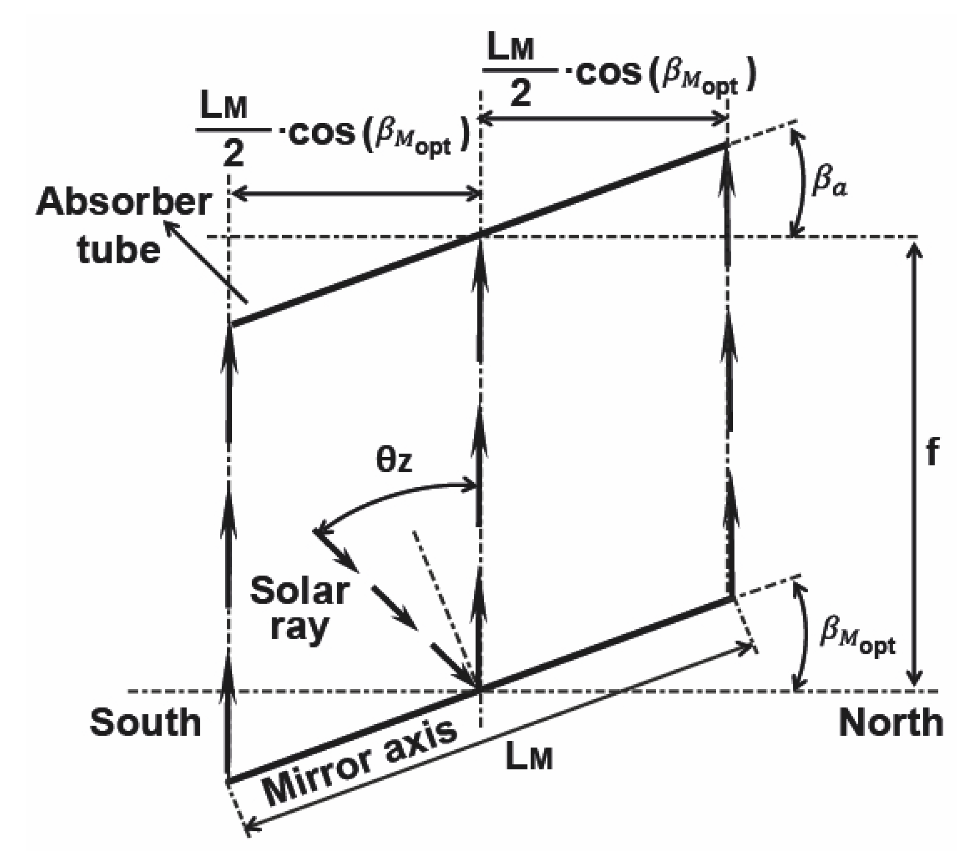
Our method is based on the fact that the rays reflected by the rows of mirrors in the longitudinal direction are vertical at solar noon (see Figure 5).
This paper is organized as follows. Section 2 presents the problem under study, while the theoretical justification is outlined in Section 3. In Section 4, a brute-force search algorithm is used to verify the proposed equations, and finally, Section 5 summarizes the main results and conclusions. An Annex includes all the formulas obtained in previous works in order to facilitate the reading of this work.

2. Overview

The final aim of this work is to maximize the ratio of total energy E ( MWh ) absorbed by the absorber tube over the area A ( m 2 ) required for the S S L F R installation, that is, the E A R :
E A R = n d = 1 365 0 24 i = 0 2 · n D N I n d ( T S ) · η o p t · I A M i n d ( T S ) · A e f f i n d ( T S ) d T S A
where D N I is the direct normal irradiance, η o p t is the optical efficiency, I A M is the incidence angle modifier, A e f f i n d is the effective area illuminated on the absorber tube by mirror i, n is the number of mirrors at each side of the central mirror, T S is the solar time, n d is the ordinal of the day.
The formulas used for computing each of the elements of (1) are included in the Annex. Notice that, among all the variables affecting the E A R , we are, in this work, only interested in the longitudinal tilt angles of the mobile structure and the secondary reflector system, i.e., β M and β a . We remark that they only appear in the formulas for the reflector length, L, and the total illuminated length of the absorber tube, l a .
On the one hand, the reflector length L can be computed using one of three laws (Equations (23)–(25)): depending on whether the projection of the absorber tube lies inside the projection of the primary field of mirrors, or whether it overflows to the left or to the right. The lengths L a l and L a r (the left and right length, respectively, of the absorber tube) appear in those laws. These quantities are design parameters of the S S L F R and calculated, in our case, by means of an algorithm presented in [12], which computes the length and place of the absorber tube, maximizing the annual energy obtained for each pair of values β M and β a .
On the other hand, the total illuminated length of the absorber tube l a is calculated from its left ( l a l ), right ( l a r ) components, whose values are given by (31) and (32).
Obviously, there is a relation between the pairs L a l and L a r (which are design values) and l a l and l a r , (true values of illuminated lengths), but it is important to realize that one cannot compute one from the other explicitly. Therefore, it is also impossible to obtain a closed formula E A R ( β M , β a ) . If we could do so, we could state the problem as a non-linear programming optimization problem:
max β M , β a E A R ( β M , β a ) g ( β M , β a ) 0 β M R , β a R max β M , β a E A R ( β M , β a ) β M min β M β M max β a min β a β a max
with no equality restrictions h ( β M , β a ) = 0 in the independent variables and with only inequality restrictions g ( β M , β a ) 0 in each of the variables, separately, as box constraints. One could use, in this case, the classical Karush–Kuhn–Tucker ( K K T ) conditions to find necessary conditions for the optimum solution of the problem. However, as explained above, we need to use a different approach.
The maximum E A R ( β M , β a ) value lies in a specific subset of R 2 : a bounded rectangular region, delimited by the minimum and maximum values of β M and β a . We shall approach the problem in two stages: as our objective is to maximize E A R , which is given by Equation (1), we first minimize A, and next, we maximize E.
Apart from the assumptions in previous works, the following one is made in the present study: the area required for the S S L F R installation cannot exceed 10 (m 2 ), and β M and β a must be between 0 and λ [14], so that the box constraints are: β M min = β a min = 0 and β M max = β a max = λ . Former calculations have proved that for angles greater than λ , the required surface area is much larger than those 10 (m 2 ), and they are out of our scope.

3. Theoretical Justification of the Optimum Tilt Angles

In order to evaluate the optimum longitudinal tilt angles β M and β a for the application of S S L F R s in urban areas, we first analyze their influence qualitatively.

3.1. Influence of β M over A and Influence of β a over E

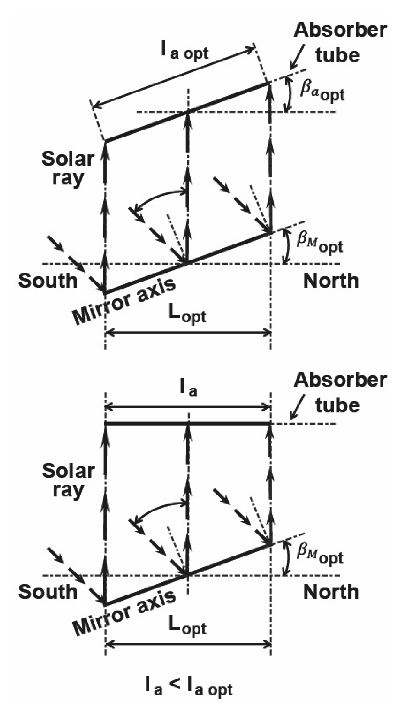
The way to minimize A is to require the rays reflected by the mirrors in the longitudinal direction to be vertical. The greater the angle between the rays reflected by the mirrors in the longitudinal direction with the vertical, the greater the total illuminated length of the absorber tube, and, as a consequence, the greater the surface area taken by the S S L F R (see Figure 2). The angle affecting the surface area required for the installation of the S S L F R is β M , whereas β a affects the energy E absorbed by the absorber tube, as increasing β a causes an increase in the total illuminated length of the absorber tube, while the surface area required for the installation of the S S L F R remains constant (see Figure 3).

3.2. Calculation of the Optimum β M

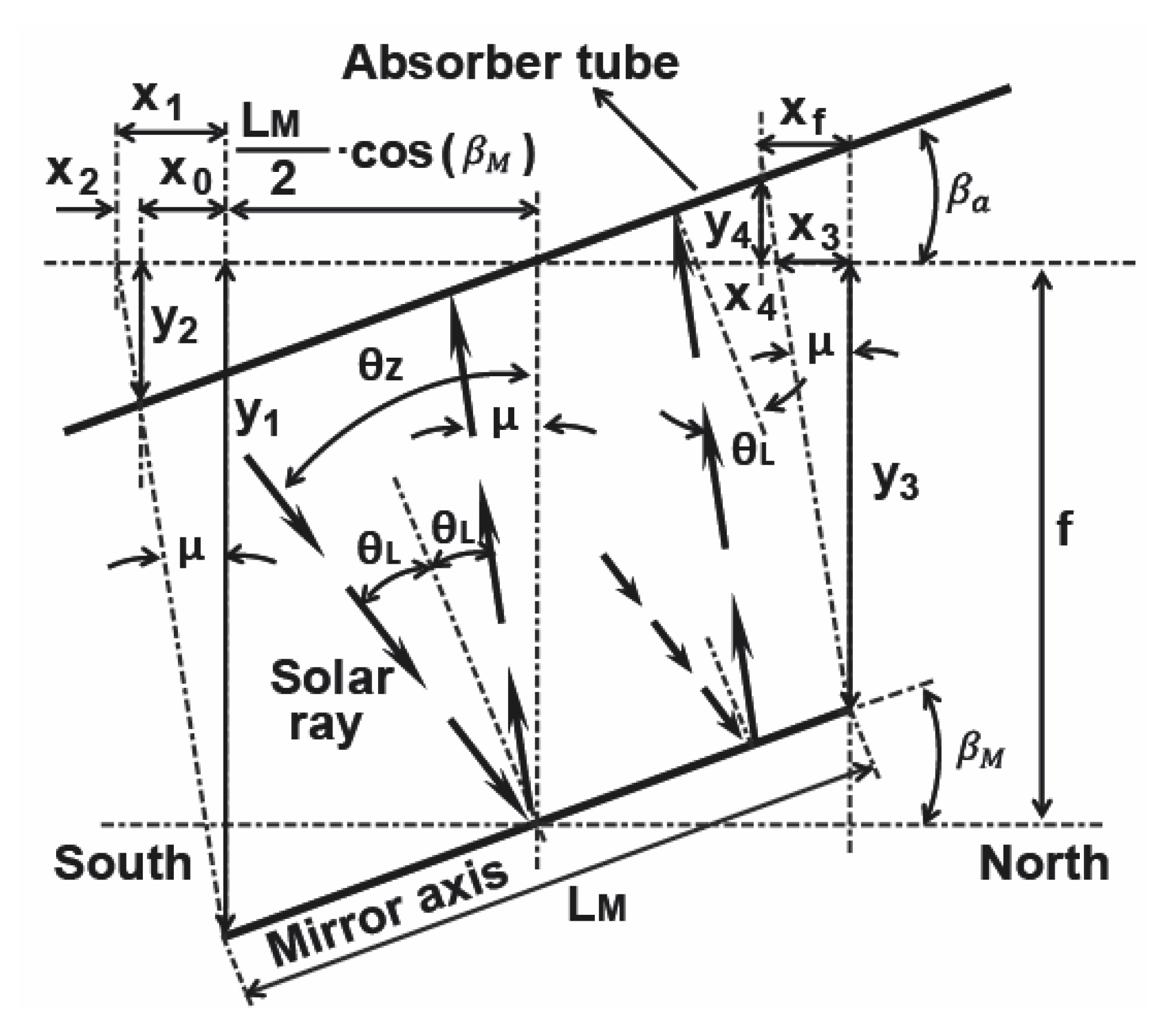
Figure 4 shows the parameters involved in this study. The value of μ is:
μ = 2 β M θ z
In order to minimize the area required for the installation of the S S L F R , we shall impose that the rays reflected by the mirrors in the longitudinal direction are vertical at solar noon, which is the moment of daily maximum radiation, throughout the year, which happens if μ = 0 (see Figure 5). The annual mean value is then:
μ ¯ = 2 β M θ z ¯ min = 0
where θ z ¯ min is the annual mean value of the zenith angle of the Sun at solar noon.
The following equation expresses the height angle of the Sun ( α S ) as a function of the declination, δ , the latitude, λ , and the hour angle, ω :
α S = arcsin [ sin δ sin λ + cos δ cos λ cos ω ]
Setting ω = 0 (solar noon), the solar height is maximum for a specific day ordinal ( n d ):
α S max = arcsin [ sin δ sin λ + cos δ cos λ ]
Computing the sine of the solar height:
sin α S max = [ sin δ sin λ + cos δ cos λ ]
and applying trigonometric equalities, we get:
sin α S max = cos λ δ = sin ( π 2 λ δ )
Thus:
α S max = π 2 λ δ
The annual mean value for the height angle is then:
α S ¯ max = n d = 1 365 π 2 λ δ n d = 1 365 n d = n d = 1 365 n d π 2 λ + n d = 1 365 δ n d = 1 365 n d
Spencer [18] provides this approximate expression for the declination in rad:
δ = 0.006918 0.399912 cos Γ + 0.070257 sin Γ 0.006758 cos 2 Γ + 0.000907 sin 2 Γ 0.002697 cos 3 Γ + 0.001480 sin 3 Γ
where Γ (the day angle in rad) is:
Γ = ( n d 1 ) 2 π 365
where n d is the ordinal of the day. The annual mean value for the declination is then:
δ ¯ = n d = 1 365 δ n d = 1 365 n d = 0.0069 ( r a d )
and we shall assume it is 0. Thus,
α S ¯ max = π 2 λ
The zenith angle of the Sun ( θ z ), is also commonly used, or the complementary angle to the height angle of the Sun ( θ z = π 2 α S ):
θ z ¯ min = π 2 α S ¯ max = λ
Substituting Equation (15) into (4) we get:
β M = θ z ¯ min 2 = λ 2
which shows that the optimum tilt angle of the mobile structure depends on the place of deployment of the S S L F R .
Figure 6 shows the value of μ for depending on β M at solar noon in Almeria. Notice how for β M = λ 2 , we have a μ ¯ of 0.

3.3. Calculation of the Optimum β a

Once the optimum value of the tilt angle of the mobile structure has been determined, the left ( l a l ) and right ( l a r ) illuminated lengths of the absorber tube can be computed, using (31) and (32) (simply imposing μ ¯ = 0 ):
l a l = L M 2 cos β M cos β a
l a r = L M 2 cos β M cos β a
The greater l a l and l a l (with the restrictions on the optimum tilt angle of the mobile structure), the greater the annual total energy absorbed by the absorber tube. From Equations (17) and (18), the maximum values will be reached when the denominator is minimum, which happens (within the allowed range β a min β a β a max ) for:
β a = λ

4. Results and Discussion

In this section, we verify the validity of Equations (16) and (19), using a brute-force search algorithm, and we confirm that these values cause the E A R for the S S L F R installation to be maximum.
We have discretized the time in 10 min steps. Using MATLAB routines, we have computed the following values: direct normal irradiance, optical efficiency, mirror position, and the effective area of the absorber tube. The shading, blocking, end loss effects, and end reflected light loss were also taken into account. The method presented by [19] is used to determine the hourly beam solar irradiance on a horizontal surface for the weather conditions of a particular site and for each day of the year. This method uses the satellite-based solar radiation data P V G I S (photovoltaic geographical information system) [20] for each city under study as input. Table 1 shows the parameters used in this study.
The European Union has combined the Köppen–Geiger classification with the European Heat Index, the European Cooling Index and the nearly zero-energy buildings ( N Z E B ) zoning to establish climatic zones with similar characteristics, shown in Table 2: C s a , temperate with dry, hot summer; C f b , temperate without dry season and warm summer; D f b , temperate continental climate/humid continental climate without dry season and with warm summer and D f c , cold, without dry season and with cold summer. Countries may have more than one climatic zone, and it is sometimes difficult to establish the prevailing climate classification of Köppen.
Equations (16) and (19) have been used in five cities. The selection criteria are: different climate zones and different latitudes. Table 3 contains our choices.
A brute-force algorithm is used to verify Equations (16) and (19). The number of possible combinations is reduced by using the following known facts: (i) the available area must not exceed 10 (m 2 ) [14]; (ii) the values of β M and β a have to be between 0 and λ .
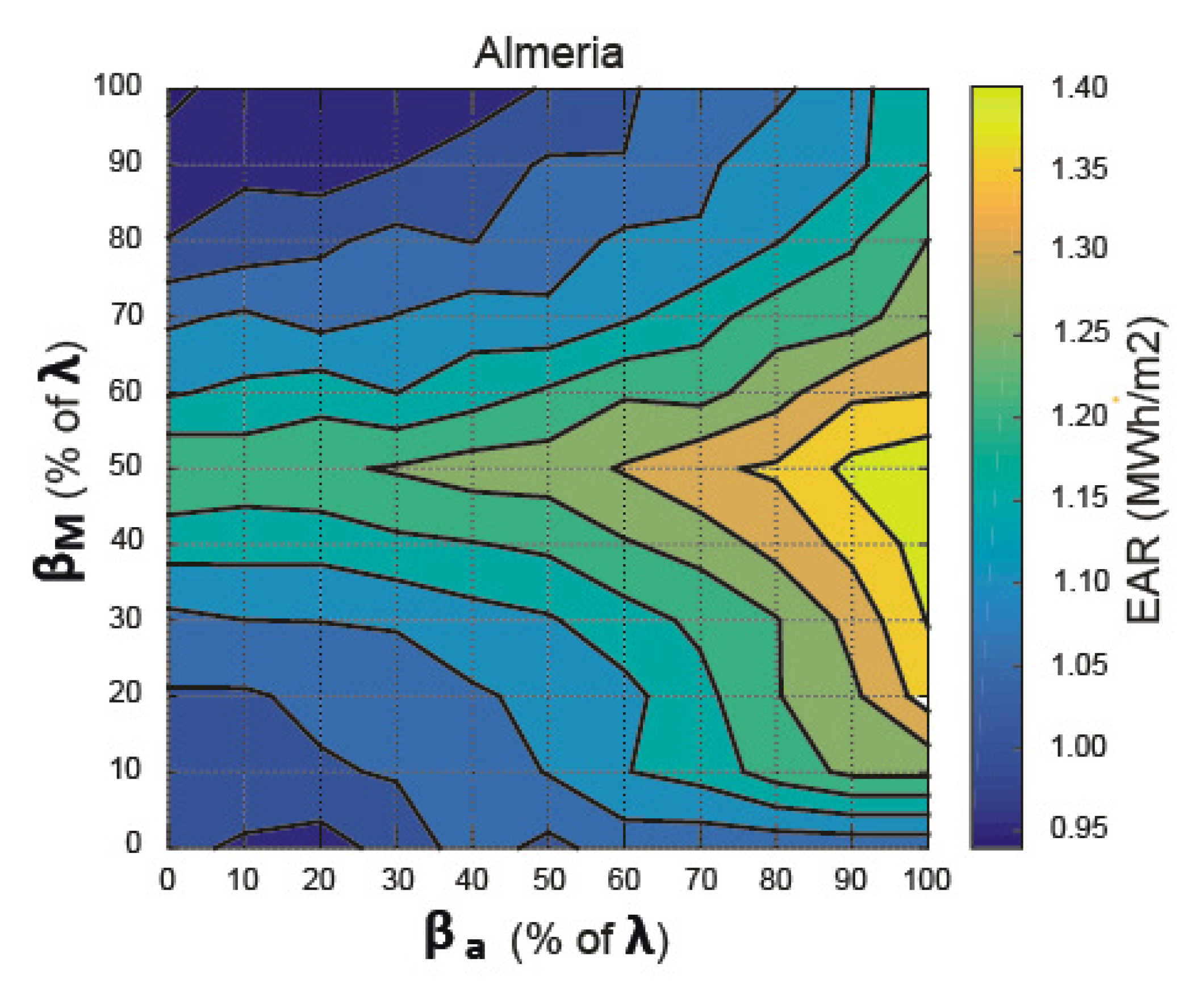
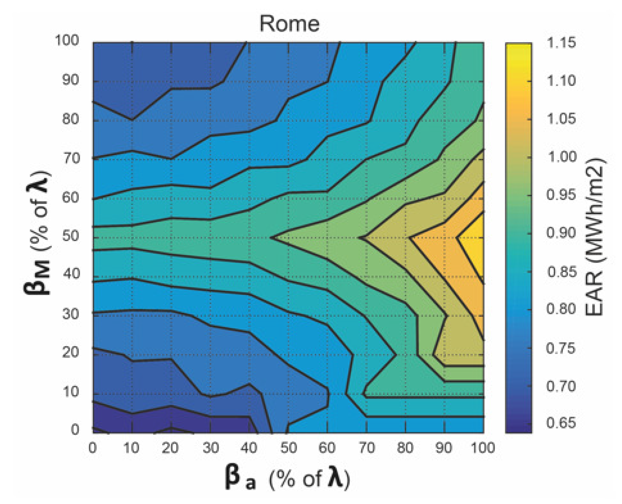
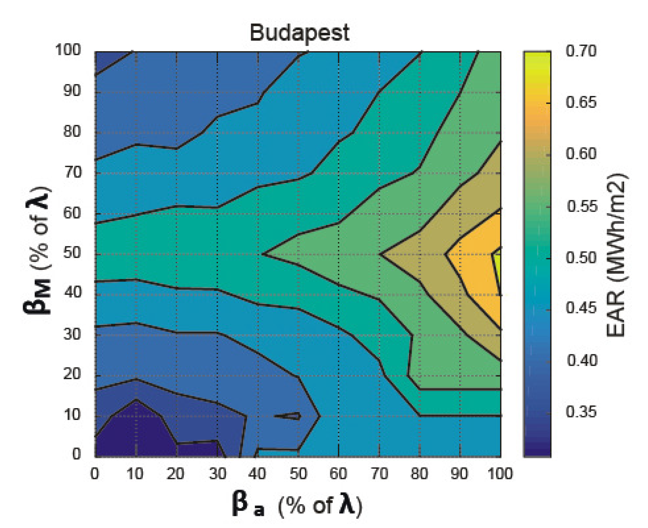
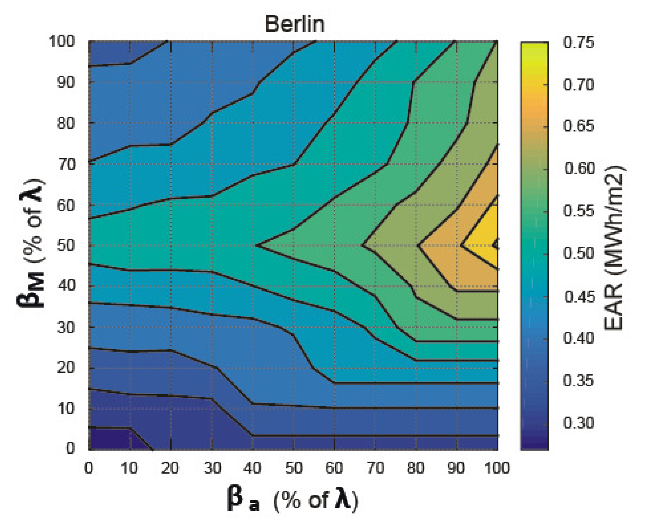
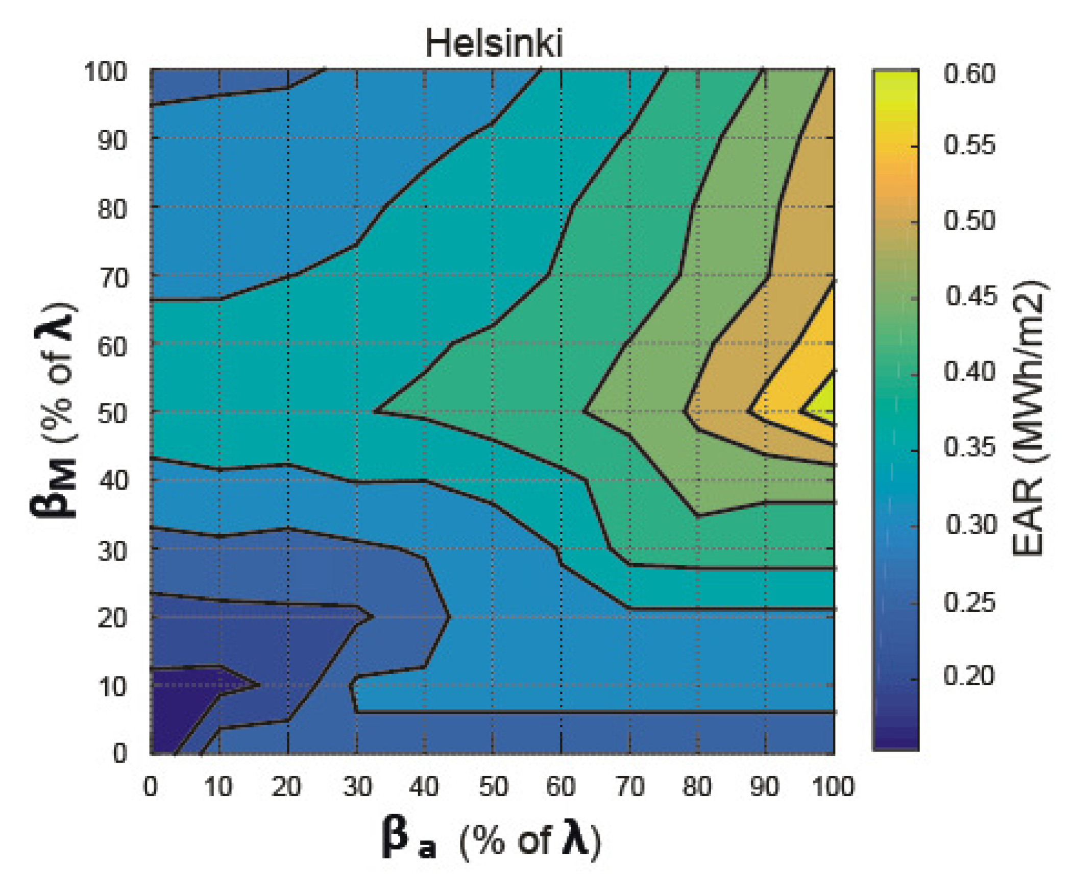
Figure 7, Figure 8, Figure 9, Figure 10 and Figure 11 contain the results of the search. They show the E A R values in Almeria, Rome, Budapest, Berlin, and Helsinki, respectively, and confirm that the equations we propose are correct for all those locations. Thus, we have verified that the following:
(1) By keeping β a constant when β M = λ 2 , one obtains the greatest E A R .
(2) For a fixed β M , an increase in β a causes an increase in E A R .
(3) The maximum value of E A R is always for β M = λ 2 and β a = λ .
The results show that the optimum longitudinal tilt angle of the mobile structure is half the latitude of the geographic location and that the optimum longitudinal tilt angle of the secondary reflector system is equal to the latitude, and we have verified this result for five cities of the European Union, each belonging to one of the five European climate zones.
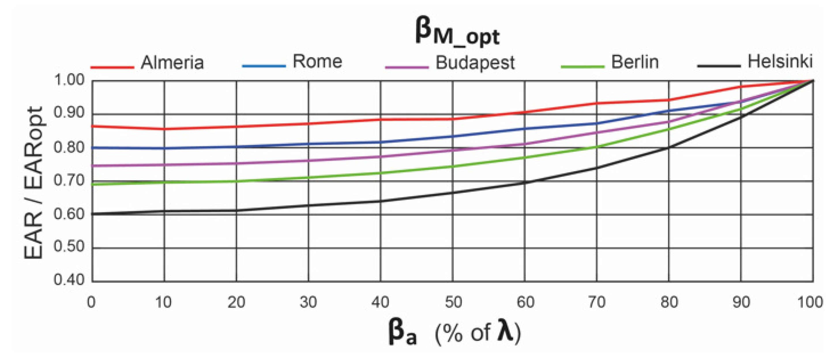
Figure 12 shows the relation between the value of E A R and the maximum value of E A R for fixed β M = λ 2 and varying β a . Deviations in relation to the optimum β a have a higher influence as the city’s latitude is higher. As the β a deviations increase, the E A R becomes lower, getting its minimum value for β a = 0 ( ). In Helsinki, 60 % of the optimum E A R is obtained for the minimum value. Values of E A R between 70 % and 87 % of the optimum E A R are obtained in the other cities.
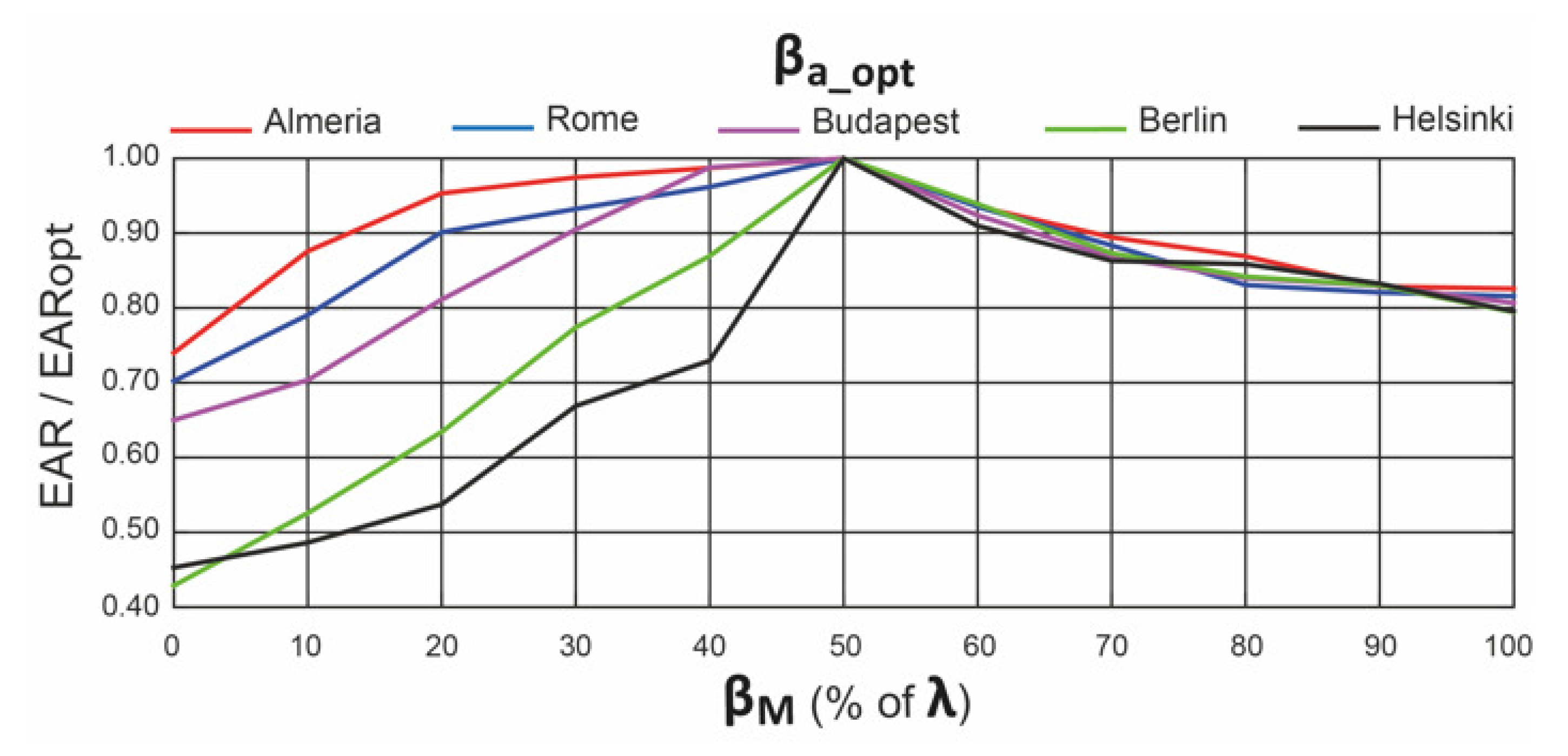
Figure 13 shows the relationship between the value of E A R and the maximum value of E A R for fixed β a = λ and varying β M . Deviations in relation to the optimum β M have a higher influence as the city’s latitude is higher, for values of β M lower than the optimum value of β M .
Notice that the influence of β M is greater than the influence of the β a .

5. Conclusions

For urban application of S S L F R s , the area required for its installation is important, and it is affected by the tilt angles of the mobile structure and the secondary reflector system. A methodology for calculating the optima of both angles is presented. Once these are determined, the algorithm proposed in [12] for calculating the optimal values of the longitudinal position and length of the absorber tube can be applied. Optimum tilt angles have been evaluated taking into account the different geographical locations. A brute-force search algorithm is used to verify the results, and several tables of different tilt angles are presented. The following are the key observations of our study: (1) The optimum tilt angles of the S S L F R depend on the geographical location. (2) The optimum tilt angle of the mobile structure is λ / 2 for any geographical location. (3) The optimum tilt angle of the secondary reflector system is λ for any geographical location. (4) For a fixed β M = λ 2 and β a , the deviations with respect to the optimum β a have a higher influence as the city’s latitude is higher. (5) For a fixed β a = λ and β M , the deviations in relation to the optimum β M have a higher influence as the city’s latitude is higher, for values of β M smaller than the optimum. (6) The influence of β M is greater than the influence of the β a .
These contributions are useful for many possible future studies related to concentrated photovoltaic systems based on S S L F R s , as our system has no moving parts, which reduces costs and power consumption.

6. Annex

In this Annex we collect all the formulae required to compute the E A R :
E A R = 1 A n d = 1 365 0 24 i = 0 2 · n D N I n d ( T S ) · η o p t · I A M i n d ( T S ) · A e f f i n d ( T S ) d T S
The area A required for the S S L F R installation is:
A = W · L
The mirror field width W is:
W = 2 · n · W M + d + W M
while the reflector length L can be computed with the following relations:
(1) If L a l · cos β a 1 2 · L M · cos β M and L a r · cos β a 1 2 · L M · cos β M then:
L = L M · cos β M
(2) If L a l · cos β a > 1 2 · L M · cos β M and L a r · cos β a 1 2 · L M · cos β M then:
L = L a l · cos β a + 1 2 · L M · cos β M
(3) If L a l · cos β a 1 2 · L M · cos β M and L a r · cos β a > 1 2 · L M · cos β M then:
L = 1 2 · L M · cos β M + L a r · cos β a
The parameter D N I is the direct normal irradiance. The method presented by [19] was used to estimate it. The parameter η o p t is the total optical yield, which is calculated considering the reflectivity of the mirrors ( ρ ), the cleanliness factors of the mirror ( C I m ) and of the glass covering the secondary absorber ( C I g ), the transmissivity of this glass ( τ ), and the absorptivity of the material of which the absorber tube is made ( α b ):
η o p t = ρ · C I m · τ · C I g · α b
The parameter I A M i expresses the variation in the optical performance of an S S L F R for varying ray incidence angles, for the i-th mirror, [12]:
I A M i = C L 2 + C T i 2 + 2 · C L · C T i · cos C L C T i ^ 1 / 2 ; 0 i 2 n
C L = cos γ S · cos θ L ; C T i = cos α S · sin γ S · cos θ i sin θ t ; 0 i 2 n
The value A e f f i is the effective area of the absorber tube of the i-th mirror, which is actually illuminated. This parameter is calculated considering the total illuminated length of the absorber tube ( l a ) and the length of the circumference illuminated on the absorber tube by the i-th mirror ( l c i a i ):
A e f f i = l c i a i · l a ; 0 i 2 n
The value of l a is the sum of the left illuminated length of the absorber tube ( l a l ), and the right illuminated length of the absorber tube ( l a r ) [12]:
l a = l a l + l a r
l a l = 1 cos β a f + L M 2 sin β M cos β M tan β a tan μ 1 + tan β a tan μ + L M 2 cos β M
l a r = 1 cos β a L M 2 cos β M f + L M 2 cos β M tan β a sin β M tan μ 1 + tan β a tan μ
The parameter l c i a i is computed considering the width on the absorber tube illuminated by the i-th mirror ( W a i ), the angle between the vertical at the focal point and the line connecting the center point of each mirror to the focal point ( α i ), and the diameter of the absorber tube (D) [12]:
l c i a i = π D 2 if   W a i cos α i > D D arcsin W a i D if   W a i cos α i D
where W a i , the width on the absorber tube illuminated by the i-th mirror, is given by:
W a i = W M · cos β i ± sin β i tan α i ; 0 i 2 n
α i being the angle between the vertical at the focal point and the line connecting the center point of each mirror to the focal point and β i the tilt of the i-th mirror. The sign ± means − for the left side and + for the right side. The angle α i is given by:
α i = arctan i · W M + d f + D / 2 ; 1 i n
Finally, T S is the solar time, n is the number of mirrors on each side of the central mirror, n d is the ordinal of the day, and A is the area required for the S S L F R installation. This parameter is calculated considering the mirror field width (W) and the reflector length (L) [13].

Author Contributions

Conceptualization: A.B. and L.B., investigation: C.B.-C. and J.A.F.R.; wrote and final editing: A.B., L.B., C.B.-C. and J.A.F.R. All authors have read and agreed to the published version of the manuscript.

Funding

This research was funded by the Business Chair: “Training and immersion in sustainable development” of the University of Oviedo.

Institutional Review Board Statement

Not applicable.

Informed Consent Statement

Not applicable.

Data Availability Statement

Not applicable.

Acknowledgments

The authors wish to thank Laudino Rodríguez, head of the CIFP-Mantenimiento y Servicios a la Producción vocational training school in La Felguera, Asturias, Spain, for his work of building the prototype for the design presented in this paper.

Conflicts of Interest

The authors declare no conflict of interest.

Abbreviations

The following abbreviations are used in this manuscript:
A e f f i Effective area of the absorber tube (m 2 )
C L g Cleanliness factor of the glass
C L m Cleanliness factor of the mirror
DDiameter of the absorber tube (m)
D N I Direct Normal Irradiance (W/m 2 )
dSeparation between two consecutive mirrors (m)
E A R Ratio between the annual energy absorbed and the area required for the S S L F R
installation (Mwh/m 2 )
fHeight of the receiver (m)
I A M Incidence angle modifier
LReflector length (m)
L M Length of the mirrors (m)
L a Length of the single absorber tube (m)
L a l Left length of the single absorber tube (m)
L a r Right length of the single absorber tube (m)
l a Total illuminated length of the absorber tube. (m)
l a l Left illuminated length of the absorber (m)
l a r Right illuminated length of the absorber (m)
l c i a i Length of the circumference illuminated on the absorber tube by the i-th mirror (m)
nNumber of mirrors at each side of the central mirror
n d Ordinal of the day
QTotal power absorbed (W)
WMirror field width (m)
W M Width of the mirrors (m)
W a i Width illuminated on the absorber by the i-th by mirror (m)
α b Absorptivity of the absorber tube
α i Angle between the vertical at the focal point and the line connecting the center
point of each mirror to the focal point ( )
α S Height angle of the Sun ( )
β a Angle between the absorber tube and the horizontal plane ( )
β i Tilt of i-th mirror ( )
β M Angle between the mirror axis and the horizontal plane ( )
γ S Azimuth of the Sun ( )
δ Declination ( )
η o p t Optical efficiency (%)
θ z Zenith angle of the Sun ( )
λ Latitude angle ( )
ρ Reflectivity of the primary mirrors
μ Angle between the reflected ray and the normal to the NS axis ( )
Γ Day angle ( )
τ Transmissivity of the glass
ω Hour angle ( )

References

  1. EUROSTAT. Eurostat, Energy Statistics—An Overview. 2017. Available online: https://ec.europa.eu/eurostat/statistics-explained/index.php?title14Energy_statistics_-_an_overview#Energy_intensity (accessed on 15 April 2021).
  2. European Commission. Energy-Heating and Cooling. 2018. Available online: https://ec.europa.eu/energy/en/topics/energyefficiency/heating-and-cooling (accessed on 15 April 2021).
  3. European Council Report. 2019. Available online: http://www.consilium.europa.eu/uedocs/cms_data/docs/pressdata/en/ec/145397.pdf (accessed on 15 April 2021).
  4. Buker, M.S.; Riffat, S.B. Building integrated solar thermal collectors—A review. Renew. Sustain. Energy Rev. 2015, 51, 327–346. [Google Scholar] [CrossRef]
  5. Mokhtar, G.; Boussad, B.; Noureddine, S. A linear Fresnel reflector as a solar system for heating water: Theoretical and experimental study. Case Stud. Therm. Eng. Case 2016, 8, 176–186. [Google Scholar] [CrossRef] [Green Version]
  6. Serag-Eldin, M.A. Thermal design of a roof-mounted CLFR collection system for a desert absorption chiller. Int. J. Sustain. Energy 2014, 33, 506–524. [Google Scholar] [CrossRef]
  7. Velázquez, N.; García-Valladares, O.; Sauceda, D.; Beltrxaxn, R. Numerical simulation of a Linear Fresnel Reflector Concentrator used as direct generator in a Solar-GAX cycle. Energy Convers. Manag. 2010, 51, 434–445. [Google Scholar] [CrossRef]
  8. Zhou, L.; Li, X.; Zhao, Y.; Dai, Y. Performance assessment of a single/double hybrid effect absorption cooling system driven by linear Fresnel solar collectors with latent thermal storage. Sol. Energy 2017, 151, 82–94. [Google Scholar] [CrossRef]
  9. Montenon, A.C.; Papanicolas, C. Economic assessment of a PV hybridized linear Fresnel collector supplying air conditioning and electricity for buildings. Energies 2021, 14, 131. [Google Scholar] [CrossRef]
  10. Boito, P.; Grena, R. Application of a fixed-receiver linear Fresnel reflector in concentrating photovoltaics. Sol. Energy 2021, 215, 198–205. [Google Scholar] [CrossRef]
  11. Barbón, A.; Sánchez-Rodríguez, J.A.; Bayxoxn, L.; Barbxoxn, N. Development of a fiber daylighting system based on a small-scale linear Fresnel reflector: Theoretical elements. Appl. Energy 2018, 212, 733–745. [Google Scholar] [CrossRef]
  12. Barbón, A.; Barbxoxn, N.; Bayxoxn, L.; Otero, J.A. Optimization of the length and position of the absorber tube in small-scale Linear Fresnel Concentrators. Renew. Energy 2016, 99, 986–995. [Google Scholar] [CrossRef]
  13. Barbón, A.; Bayxoxn, L.; Bayxoxn-Cueli, C.; Barbxoxn, N. A study of the effect of the longitudinal movement on the performance of small scale linear Fresnel reflectors. Renew. Energy 2019, 138, 128–138. [Google Scholar] [CrossRef]
  14. Barbón, A.; Bayxoxn-Cueli, C.; Bayxoxn, L.; Rodríguez, L. Investigating the influence of longitudinal tilt angles on the performance of small scale linear Fresnel reflectors for urban applications. Renew. Energy 2019, 143, 1581–1593. [Google Scholar] [CrossRef]
  15. Nixon, J.D.; Davies, P.A. Construction and experimental study of an elevation linear Fresnel reflector. J. Sol. Energy Eng. 2016, 138, 031001. [Google Scholar] [CrossRef]
  16. Pulido-Iparraguirre, D.; Valenzuela, L.; Serrano-Aguilera, J.J.; Fernández-García, A. Optimized design of a Linear Fresnel reflector for solar process heat applications. Renew. Energy 2019, 131, 1089–1096. [Google Scholar] [CrossRef]
  17. Barbón, A.; Sánchez-Rodríguez, J.A.; Bayxoxn, L.; Bayxoxn-Cueli, C. Cost estimation relationships of a small-scale linear Fresnel reflector. Renew. Energy 2019, 134, 1273–1284. [Google Scholar] [CrossRef]
  18. Spencer, J.W. Fourier series representation of the position of the sun. Search 1971, 2, 172. [Google Scholar]
  19. Barbón, A.; Ayuso, P.F.; Bayxoxn, L.; Fernández-Rubiera, J.A. Predicting beam and diffuse horizontal irradiance using Fourier expansions. Renew. Energy 2020, 154, 46–57. [Google Scholar] [CrossRef]
  20. PVGIS. Joint Research Centre (JRC). 2021. Available online: http://re.jrc.ec.europa.eu/pvg_tools/en/tools.html#PVP (accessed on 15 April 2021).
  21. Zhu, Y.; Shi, J.; Li, Y.; Wang, L.; Huang, Q.; Xu, G. Design and thermal performances of a scalable linear Fresnel reflector solar system. Energy Convers. Manag. 2017, 146, 174–181. [Google Scholar] [CrossRef]
  22. Zhu, Y.; Shi, J.; Li, Y.; Wang, L.; Huang, Q.; Xu, G. Design and experimental investigation of a stretched parabolic linear Fresnel reflector collecting system. Energy Convers. Manag. 2016, 126, 89–98. [Google Scholar] [CrossRef]
  23. Duffie, J.A.; Beckman, W.A. Solar Engineering of Thermal Processes, 4th ed.; John Wiley & Sons: New York, NY, USA, 2013. [Google Scholar]
  24. Sharma, V.; Khanna, S.; Nayak, J.K.; Kedare, S.B. Effects of shading and blocking in compact linear fresnel reflector field. Energy 2016, 94, 633–653. [Google Scholar] [CrossRef]
  25. Theunissen, P.H.; Beckman, W.A. Solar transmittance characteristics of evacuated tubular collectors with diffuse back reflectors. Sol. Energy 1985, 35, 311–320. [Google Scholar] [CrossRef]
  26. Kottek, M.; Grieser, J.; Beck, C.; Rudolf, B.; Rubel, F. World map of the Köppen-Geiger climate classification updated. Meteorol. Z. 2006, 15, 259–263. [Google Scholar] [CrossRef]
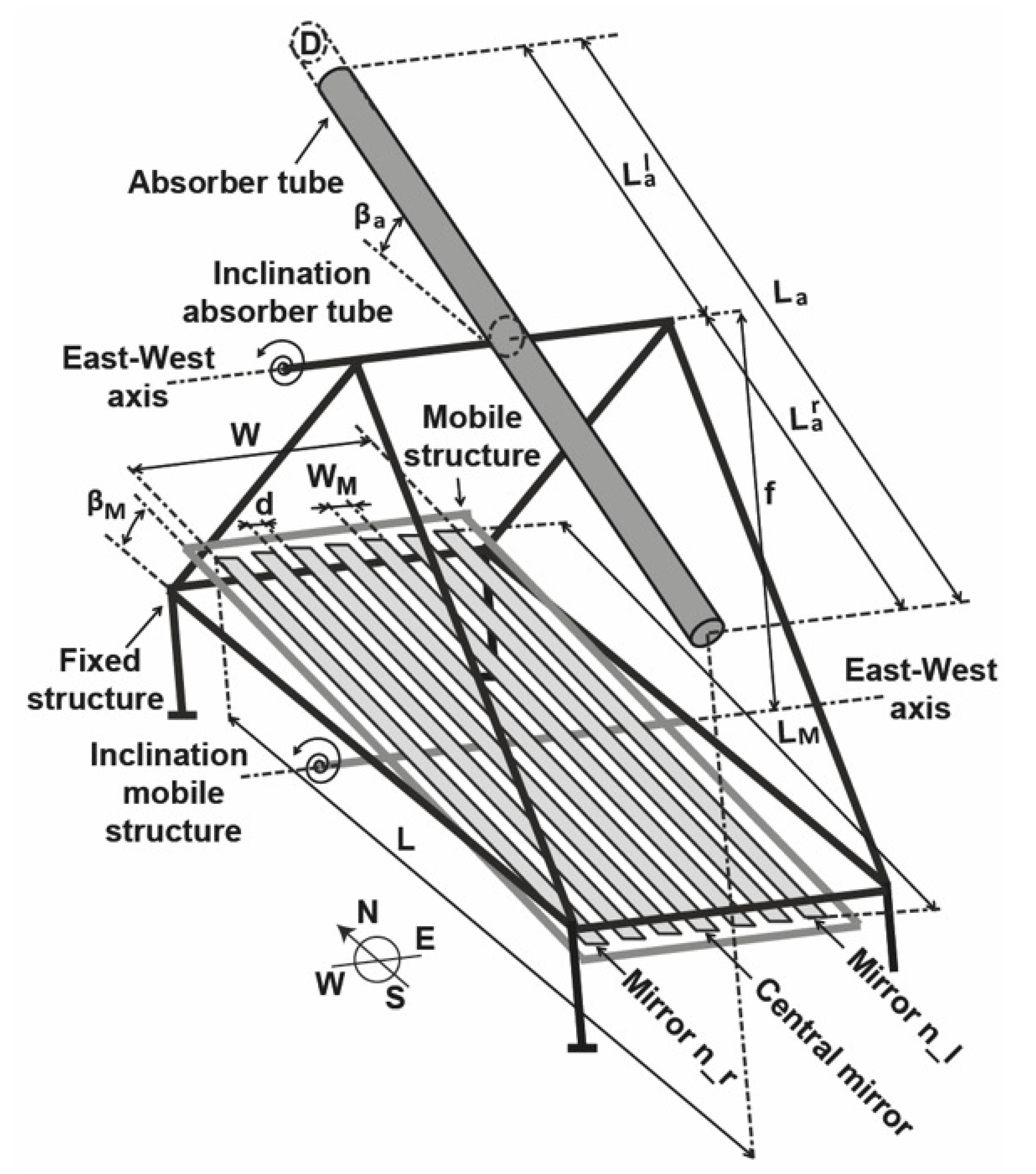
Figure 1. Simplified schematics of a generic S S L F R .
Energies 14 02883 g001
Figure 2. Influence of β M .
Energies 14 02883 g002
Figure 3. Influence of β a .
Energies 14 02883 g003
Figure 4. Schema of the longitudinal plane.
Energies 14 02883 g004
Figure 5. Case with μ = 0 .
Energies 14 02883 g005
Figure 6. Value of μ for several β M values.
Energies 14 02883 g006
Figure 7. EAR in Almeria.
Energies 14 02883 g007
Figure 8. EAR in Rome.
Energies 14 02883 g008
Figure 9. EAR in Budapest.
Energies 14 02883 g009
Figure 10. EAR in Berlin.
Energies 14 02883 g010
Figure 11. EAR in Helsinki.
Energies 14 02883 g011
Figure 12. Influence of β a .
Energies 14 02883 g012
Figure 13. Influence of β M .
Energies 14 02883 g013
Table 1. Constant parameters in the study.
Param.ValueReferences
n12[12,14]
W M 0.06 [12,14,21]
d 0.024 [12,14]
D 0.0486 [12,14]
f 1.5 [12,14,21,22]
L 2.0 [12,14]
ρ 0.94 [23]
C L m 0.96 [24]
C L g 0.96 [24]
τ 0.87 [25] ( α i 20 )
τ 0.85 [25] ( 20 α i   30 )
Table 2. Cities in NZEB climate zones.
ZoneCitiesKöppen [26]
Zone 1Athens, Larnaca-Luga-Catania-Almeria-Palermo C s a
Zone 2Lisbon-Madrid-Marseille-Rome C s a / C f b
Zone 3Bratislava-Budapest-Ljubljana-Milan-Venice D f b
Zone 4Amsterdam-Berlin-Brussels-Copenhagen-Dublin-London-Macon-Nancy-Paris-Prague-Warszawa C f b / D f b
Zone 5Helsinki-Riga-Stockholm-Gdansk-Tovarene D f c
Table 3. Cities under study.
ZoneCitiesLatitudeLongitudeAltitude
Zone 1Almeria (Spain) 36 50 07 N 02 24 08 W22 (m)
Zone 2Rome (Italy) 41 53 30 N 12 30 40 E52 (m)
Zona 3Budapest (Hungary) 47 29 52 N 19 02 23 E111 (m)
Zone 4Berlin (Germany) 52 31 27 N 13 24 37 E37 (m)
Zone 5Helsinki (Finland) 60 10 10 N 24 56 07 E26 (m)
Publisher’s Note: MDPI stays neutral with regard to jurisdictional claims in published maps and institutional affiliations.