Abstract
Small-spacing twin-well (SSTW) salt caverns have an extensive application prospect in thin or bedded rock salt formations due to their good performance, while they are rarely used in ultra-deep formations. The target strata depth of Pingdingshan salt mine is over 1700 m, and it is planned to apply an SSTW cavern to construct the underground gas storage (UGS). A 3D geomechanical model considering the viscoelastic plasticity of the rock mass is introduced into Flac3D to numerically study the influence of internal gas pressure, cavern upper shape and well spacing on the stability of an SSTW salt cavern for Pingdingshan UGS. A set of assessment indices is summarized for the stability of gas storage. The results show that the minimum internal gas pressure is no less than 14 MPa, and the cavern should not be operated under constant low gas pressure for a long time. The cavern with an upper height of 70 m is recommended for Pingdingshan gas storage based on the safety evaluation and maximum volume. The well spacing has a limited influence on the stability of the salt cavern in view of the volume shrinkage and safety factor. Among the values of 10 m, 20 m and 30 m, the well spacing of 20 m is recommended for Pingdingshan gas storage. In addition, when the cavern groups are constructed, the pillar width on the short axis should be larger than that on the long axis due to its greater deformation in this direction. This study provides a design reference for the construction of salt cavern gas storage in ultra-deep formations with the technology of SSTW.
1. Introduction
Underground storage is more and more prevalent in energy storage with its many advantages such as large storage capacity, strong mobility, long service life and higher safety than ground facilities [1,2,3,4]. Four types of gas storage (depleted or abandoned gas reservoir, salt cavern, aquifer gas storage and underground mine cavity) are utilized at present for natural gas storage, CO2 sequestration, nuclear waste disposal and other chemical waste burying [5,6,7]. There are more than 630 underground storages in the world, distributed in 35 countries [8]. With the development of the economy and the promotion of environmental protection awareness, more and more attention is being paid to clean energy exploitation and utilization by many countries around the world [9]. Natural gas, as one of the cleanest energies, is taking an increasing proportion of energy usage after entering the 21st century. It can be used in daily activities for different purposes such as heating, cooking and producing electricity. In China, the government is carrying out the replacement of coal with natural gas to abate air pollution. This work brings rapid growth of the gas consumption demand in society. Due to the uneven distribution of gas reservoirs in China, plenty of natural gas needs to be transported by pipelines from the western region, where there are many gas reservoirs found and developed, to the east and central regions, with big cities and dense populations, which is called the “West-to-East natural gas transmission project” [10,11]. Influenced by season, more gas consumption is required for heating in winter, meaning that lots of facilities need to be prepared for storing the gas in advance to alleviate the pressure of gas utilization. Therefore, in the last century, the Chinese government began to work on the construction of underground gas storage [12]. Thus far, more than 25 gas storages have been successfully built and put into operation.
Salt rock is found to have especial characteristics such as good creep behavior, low permeability and good damage recovery and thus is recognized as an ideal medium for energy storage [13,14,15,16]. Moreover, it is easy soluble in water, and the brine can be delivered to a salt processing factory for salt production. Therefore, the underground salt strata with good geological conditions and rock properties can be found and developed into caverns to store oil/gas by the solution mining method. The first salt cavern was utilized in the early 1940s in Canada for storing liquefied petroleum gas. At present, there are more than 70 salt cavern gas storages in the world [17]. Most cavities are constructed in a thick salt dome in Europe and America. The construction method of the single-well (SW) mining operation is adopted to develop a vertical cavern for these storage facilities [18,19,20]. In China, the salt formation used to build gas storage generally contains many interlayers such as mudstone or anhydrite [21,22]. These interlayers do not dissolve in water and easily cause an irregular cavern structure with the risk of instability when the SW vertical cavity is selected. Based on the actual geological conditions of salt mines and the urgent demand for salt cavern UGS in China, a large number of studies have been carried out on the collapse mechanism of interlayers and the stability of salt caverns with intercalations. Shi et al. [23,24] studied the effect of brine immersion with different concentrations on the tensile strength weakening of the mudstone interlayer with different salt contents and discussed the collapse control technology for interbeds in solution mining for salt cavern gas storage. Qu [25] established a mechanical model for interlayer collapse considering a dissolving side bottom corner and horizontal stress to investigate the stress distribution in the interlayer. A method covering the immersion time and temperature was proposed for determining the destruction and collapse of the interlayer. Wang et al. [26] combined field data and investigated the technology for controlling the collapse of a thick interlayer during salt cavern construction. Zheng et al. [27] proposed a new design method of fully soaking the interlayer and building the trench one more time to enlarge the space for thick-sandwich salt cavern UGS. Liu et al. [28] analyzed the influence of the permeability of three typical interlayers on the tightness of energy storage in deep-bedded salt formations. The results showed that there was a low permeability in the compressed interlayer, which was beneficial to the sealing performance of gas storage. Tang et al. [29] obtained the stress–strain characteristics of rock salt, mudstone and bedded salt and compared their deformation and failure under different stress conditions. Li [30] studied the effect of the number, thickness and dip angle of the interlayer on the stability of salt cavern UGS. All the above efforts have promoted the successful construction of salt cavern gas storage in bedded salt formations in China.
Due to the existence of an insoluble interlayer, the mining method of an SW water solution is not fully adapted to build salt cavern UGS in thin salt strata in China. To make use of layered salt strata, the method of small-spacing twin wells for cavity construction is proposed. This method uses two wells for water injection and brine withdrawal during salt cavern mining. One is used to inject water, and the other is used to produce a saturated salt solution. The “small-spacing” aspect means the tiny distance between two boreholes. This distance does not exceed 30 m. There are no inner tubes in the pipe of the water injection and withdrawal wells, different from the SW mining method with an intermediate pipe and a central pipe. The result indicates the bigger diameter of tubes can be utilized for cavity mining. Furthermore, a large displacement can be adopted and a faster speed of cavern making can be obtained with them. In addition, the distribution of the salt cavern is bigger in the horizontal direction than that of SW, meaning that the smaller height can be used to adapt to a salt formation with more interlayers. Some research has been conducted on the construction of cavities with the SSTW method. Jiang et al. [31] studied the flow field characteristics during cavern construction by using an indoor similarity experiment. Ren et al. [32,33] and Yi et al. [34] analyzed the shape of cavity expansion with different techniques of pipe lifting when the cavern was being built. The result showed that the advantage of the SSTW mining method appeared in the early time of cavity making compared with the SW mining method. Chen et al. [35] investigated the influence of internal pressure and different well spacings on the stability of SSTW salt caverns. The current research has mostly focused on the fluid flow field distribution and cavity mining method in the process of cavern construction with double wells, while little attention has been paid to the stability of the cavity. Safety evaluation is the preliminary and significant work for the design of underground salt caverns. Therefore, the purpose of this paper is mainly to analyze the influence of various upper shapes and well spacings on the stability of an SSTW salt cavern in an ultra-deep formation. Some suggestions are proposed for the construction of this type of UGS.
2. Numerical Model Establishment
Based on the geomechanical conditions of Pingdingshan salt mine, Hubei Province, the mechanical parameters and constitutive models of different rocks are obtained from experiments. Several shapes of salt cavern are designed, and the corresponding 3D geomechanical models are established for numerical simulation. A set of assessment criteria is adopted to guarantee the safety of the SSTW cavern under different working conditions.
2.1. Geological Conditions of Pingdingshan Salt Mine
Pingdingshan salt mine is located in Pingdingshan City of Henan Province in China. There are many railways and national roads nearby that provide convenient transportation for its development. The second route of the West–East gas transmission project passes by this salt mine, with the distance of 35 km between them. To provide fundamental gas storage facilities for this project and relieve the seasonal gas supply unbalance for big cities nearby, a large number of salt cavern UGSs are in demand. In this salt mine, the main salt deposition sequence is situated in Wuyang sag, which stretches for 40 km from west to east and 10 km from south to north in plane. According to the data from exploratory well PT-1, there are 21 salt-bearing groups from top to bottom in this sag, which has few faults, a small fault distance and good tightness. Among the salt groups, there are different thicknesses, and the maximum one is 75.2 m. The average thickness of them is more than 15 m, except the 4th salt group. Moreover, the average ore-bearing rate is 63% in these groups. The groups from 14th to 20th have a higher average content of rock salt at over 73%. There are 13 single salt beds within them, seven of which have a thickness greater than 10 m. The larger thickness, higher ore-bearing rate and less interlayers make the 14–20 salt groups an ideal location for the construction of UGS. The depth of the target salt formation ranges from 1708 to 2017 m, with a total thickness of 309 m. In the upper and lower parts of this interval, there exist some thick and tight mudstone formations, providing good cap rocks for the UGS.
2.2. Mechanical Parameters and Creep Model
The geological data show that the target formation mainly contains a mudstone interlayer, salt rock and bedded salt in Pingdingshan salt mine. Based on the uniaxial and triaxial compression tests, Brazilian disc tests and other relevant research work [3,12], the mechanical parameters of these rocks were obtained. The stress–strain curves of part of rock samples are shown in Figure 1 and Figure 2. From the figures, the radial strain and axial strain of rock salt is obviously larger than those of mudstone and bedded salt when the axial stress is at the peak strength. The minimum deformation happens in the mudstone interlayer. From the experiment results, the mechanical parameters of bedded salt are close to those of rock salt. Therefore, during the numerical simulation, layered salt was considered as rock salt. As the mudstone at the top and bottom of the target salt layer was not available, the mechanical parameter of it was set according to the mudstone intercalation parameters and other relevant studies for the numerical simulation. The mechanical parameters of mudstone, rock salt and the interlayer are shown in Table 1. The insolubles such as the interlayer are deposited in the form of small fragments at the bottom of the cavity. Their mechanical parameters are hard to be measured, and thus 10% of mechanical parameters of the interlayer are assumed as those of the insolubles for the numerical simulation.
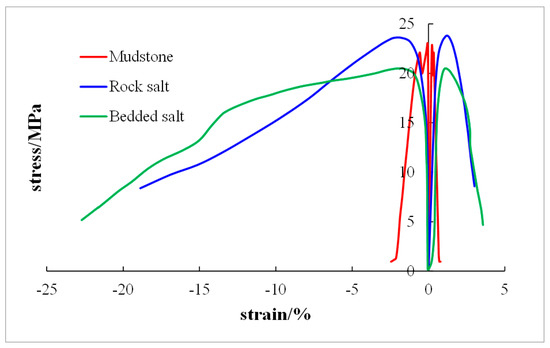
Figure 1.
Stress-strain curves of mudstone, rock salt and bedded salt in uniaxial compression tests.
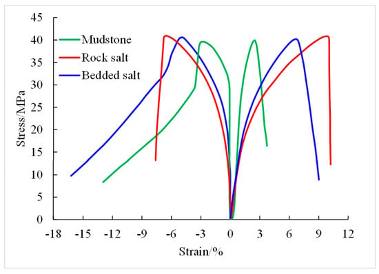
Figure 2.
Stress-strain curves of mudstone, rock salt and bedded salt in triaxial compression tests with confining pressure of 20 MPa, 25 MPa and 30 MPa.

Table 1.
Mechanical parameters of Pingdingshan rock salt.
Rock salt is a typical material with the property of creep under stress difference. A large number of creep experiments show that there exist three creep stages concerned with rock salt, which are the initial creep stage, the steady creep stage and the accelerated creep stage. The initial creep stage is completed in a short time. Compared with the several years of the steady creep stage, the initial creep can be ignored. Generally, the long-term stability of salt caverns is paid more attention during safety evaluation, meaning that the steady creep stage of rock salt is studied more frequently. Additionally, the accelerated creep stage is not taken into account for the assessment. Figure 3 shows the creep curve of rock salt cored from Pingdingshan salt mine. The result indicates the creep rate increases with stress difference. The accelerated creep stage is not attained even though the stress difference is up to 30 MPa. A large number of creep tests were carried out and various creep models were proposed to obtain the creep behaviors of rock salt. According to the results of creep tests and numerous other research works, the Norton Power model is widely adopted [36,37], and a good match for Pingdingshan rock salt was observed. The equation is expressed as
where is the steady creep rate. A and n are material parameters that can be obtained by the fitting of experiment data. . Here, is the second invariant of the deviatoric stress tensor, and , is stress deviation.
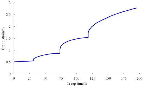
Figure 3.
Creep curve of rock salt from Pingdingshan salt mine. The test contains four stress conditions with confining pressure and axial stress of (20, 35), (20, 40), (20, 45) and (20, 50).
When the triaxial creep of rock salt is studied, the steady creep model can be written as
where and are the maximum and minimum stresses, respectively. By fitting test data of Pingdingshan rock samples, the creep mechanical parameters of the rock salt are ,. The parameters for the mudstone interlayer are ,.
2.3. Goemechanical Model and Boundary Conditions
Based on the geological condition of the salt mine, the target formation including seven interlayers is shown in Figure 4. There is a thicker intercalation with a thickness of 13 m that should be avoided during the design of UGS. Therefore, the salt groups above this interlayer were selected for gas storage construction. According to the geological data of Pingdingshan salt mine, a 3D geological model was established to investigate the mechanical response of surrounding rock about the cavern under different conditions. The model presents a cubic size with the length of 800 m, the width of 400 m and the height of 1200 m, as shown in Figure 5, where half of the whole model is for the symmetry of the model and improving the calculation efficiency. Some interlayers which are far away from the cavity were ignored, and the salt layer thickness of gas storage construction was set to 435 m. From top to bottom of the salt layer, there exist seven intercalations with thickness of 8 m, 4 m, 5 m, 4 m, 5 m, 3 m and 13 m, and six of them pass through the cavity. The thicknesses of mudstone in the upper and lower parts of the salt formation are all set to 382.5 m. To simplify the calculation, an overlying pressure with a value of 28.93 MPa was applied on the top surface of the model calculated based on the actual depth and the average density of the overburden strata (). The four lateral surfaces of the model were all fixed to constrain their horizontal displacement, meaning they are just allowed to produce displacement in the vertical direction. The displacement of the model bottom is limited to zero in all directions. Considering that in the long-term rheological environment, the unbalanced stress in the rock salt formation is released with time, the in situ stress of the formation is assumed to be equal to hydrostatic pressure, which means the three principal stresses are equal to each other. The in situ stress was loaded by the gravity gradient of 0.023 MPa/m, and its redistribution was firstly calculated before creep analysis during the numerical simulation. The whole model was meshed by using a tetrahedron element with a total number of 354,142 elements and 64,026 nodes. To improve the calculation efficiency, the element has a small size around the cavern, and away from the cavity, the mesh density decreases gradually with an increase in the distance. The entire model was established in the ABAQUS [38] software (ABAQUS 2016, Dassault Systems Inc, Vélizy-Villacoublay, France), and the mesh quality was checked to eliminate the effect of a poor mesh on the numerical results. The finite difference software Flac3D [39] (Flac3D VS 6.0, Itasca Consulting Group Inc, Minneapolis, MN, USA) is widely used to deal with rock and soil engineering problems for its outstanding advantage of solving large displacement problems. In addition, there are many rock and soil constitutive models provided by this software. Among them, the Cpower model is composed of the Mohr–Coulomb criterion and the Norton Power creep model and is widely used in creep engineering of underground excavation. This viscoplastic model was also adopted to analyze the stability of salt cavern gas storage for Pingdingshan salt mine. In this paper, the 3D geomechanical model was introduced into Flac3D software to conduct the numerical analysis. Tecplot [40] software was used for the post-processing of the results because of its powerful post-processing function. The maximum unbalanced force was monitored to check the convergence of the model during the calculation.
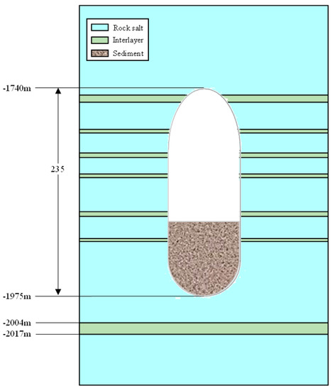
Figure 4.
Schematic diagram of the target salt formation and the cavern shape for the construction of SSTW gas storage for Pingdingshan salt mine.
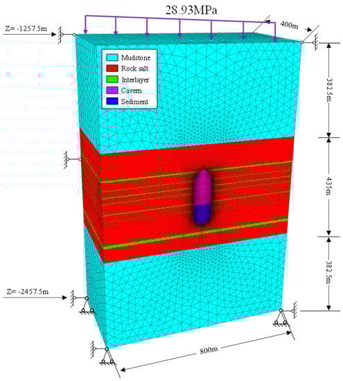
Figure 5.
3D geomechanical model of the salt cavern UGS of Pingdingshan salt mine.
2.4. Cavern Shape Optimization Scheme
With the rapid growth of the natural gas consumption demand in China, more and larger salt cavern UGSs are required for relieving the pressure of the seasonal gas supply unbalance and pipe network gas transmission. Taking the time of cavity building into consideration, double wells will be adopted to construct the salt cavern in Pingdingshan salt mine for their advantage of rapid cavity construction. As a new method, the technology of two-well cavity construction has been applied abroad, such as GEOSEL-MANOSQUE UGS in France, and Zuidwending UGS in Holland. In China, the pilot test of this technology has been carried out in Yunying salt cavern gas storage in Hubei Province, and good results have been achieved. The exploit of this method in Pingdingshan gas storage is also the experimental application and promotion of this technology. After more than ten years of research on insoluble interlayers, the deformation and collapse mechanism of the interlayer has been further understood. The construction of gas storage in salt formations with multi-interlayers has been realized. In the process of cavity dissolution, the insoluble interlayers will deposit at the bottom of the cavity and occupy a certain space that will reduce the effective storage volume of the cavern. Hence, a larger cavity volume is in demand for gas storage to meet the economic requirement. Considering the constructed cavity located in the ultra-deep formation in Pingdingshan salt mine, high pressure is an objective factor and poses a threat to the stability of salt cavern UGS. As it is the first time building a cavity by using twin-well technology in such deep strata, the shape of the salt cavern needs to be further designed and studied based on the maximum volume and stability principle.
Moreover, according to previous research of physical model experiments, the horizontal section of a cavity built by double wells is approximately elliptical and the bottom structure of the cavern is like a bowl. Seen from the vertical direction, the cavity body shape is similar to an elliptic cylinder. As laboratory experiments are limited by the model size and cannot reflect the mechanical stability of the salt cavern, the shape of the double-well cavity needs further exploration. In addition, the construction of salt cavern UGS is a complicated and time-consuming system project. At present, the time of building an SW salt cavern gas storage needs 1–2 years if running smoothly, or more than 3–4 years while encountering some tough problems. The gas storage after completion needs to meet the working life of at least 20 years. For these reasons, a good shape of the cavern is very important for engineers. Referring to the shape of SW gas storage, the pressure arch structure was adopted as the shape of the cavern roof, and the structure of the cave mined by two wells was designed as shown in Figure 4. The cavity shape mainly consists of three parts which are the pressure arch roof, elliptic cylinder body and elliptic bowl bottom. The height of the double-well salt cavern was set as 235 m according to the thickness of the target salt formation in Pingdingshan salt mine. Compared with SW gas storage, salt cavern UGS construction by twin wells is not widely applied in the world. The reasonable spacing between two wells and the cavity shape are still the focus of current research. The research work of Wang et al. [41] suggested that the shape of the cavity roof had a great influence on the stability of the cavity. Chen et al. [35] thought that a bigger ratio of the long axis to the short axis (RLS) of the transverse section means a flatter cavern shape and less stability. There is a length limit for the space between two wells. Therefore, in order to ensure stability and obtain a larger effective volume at the same time, a sound cavity roof structure and two-well spacing will be made a profound study in this paper. Learning from the pilot test of Yunying SSTW gas storage in Hubei Province, the well spacing of 20 m was adopted, and the ratio of the long axis to short axis (RLS) of the horizontal elliptical section was set with a value of 1.33, as shown in Figure 4. The corresponding length of the horizontal long axis is 80 m, and the length of short axis is 60 m. Based on this ratio of the transverse section, three cavity upper heights of 40 m, 70 m and 100 m were simulated to determine which one could obtain the maximum cavity volume under the condition of stability, as shown Figure 6a–c. Then, according to the optimal roof structure, the ratios of 1.17 and 1.5 were designed together with the ratio of 1.33 to study the influence of different horizontal elliptical sections on stability of gas storage caverns, as shown in Figure 6d–f. The space occupied by the insoluble sediment was also considered in the cavern model. The whole cavern volume is separated into upper and lower parts. About two fifths of the volume is taken over by slummage. The established model is consistent with the real situation as far as possible.
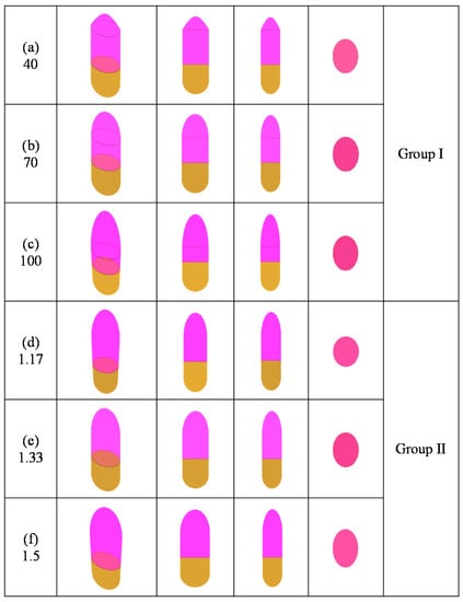
Figure 6.
Design scheme of two groups of six cavern shapes. Group Ⅰ has three top structures of 40 m (a), 70 m (b) and 100 m (c). Group Ⅱ shows three types of transverse section with RLS of 1.17 (d), 1.3 (e) and 1.5 (f).
2.5. Assessment Criterion and Working Conditions
Since salt cavities were found to be able to store energy such as oil and gas, a large number of studies have been carried out on the stability assessment of salt caverns. An index system composed of displacement, plastic zone, volume shrinkage, dilatancy safe factor (SF) and equivalent strain (ES) is summarized to evaluate the safety of salt cavern UGS during the stability analysis. The displacement of cavity walls increases with time, caused by rock salt creep. The Mohr–Coulomb criterion is used to judge whether the surrounding rock of cavity walls enters the plastic zone. Volume shrinkage is used to characterize the reduction ratio of cavity volume loss to its original volume. The allowed ratio is 30% after operating for 30 years according to most research on salt cavern gas storage and geological data of Pingdingshan salt mine. The dilatancy safe factor is a dilatancy damage criterion for rock salt that can be expressed by
where is the first invariant of the stress tensor and is the second invariant of the deviatoric stress tensor. According to DeVries et al. [42], Wang et al. [41] and Yang et al. [12], indicates local damage, indicates failure and shows collapse. The equivalent strain (ES) is adopted to assess the plastic damage of the rock mass. The ES is expressed by
where is the deviatoric stain tensor. The ES of the rock mass around the cavern should be less than 3% during the 30 years of its working lifetime [36].
The majority of previous studies demonstrated that the maximum internal gas pressure cannot exceed 80% of the overburden pressure or fracture pressure at the depth of the casing shoe. The roof depth of Pingdingshan salt cavern gas storage is 1740 m. Based on the density of the overlying salt layer, the maximum allowable gas pressure can be calculated as about 32 MPa. However, there is no clear calculation method for the minimum internal gas pressure. Creep test results show that the rock salt can enter into the accelerated creep stage under larger differential stress. The creep experiment of rock salt of Pingdingshan salt mine did not reach the accelerated creep stage under the differential stress of 30 MPa. For safety reasons, 30 MPa was assumed to be the critical stress difference between the steady creep stage and accelerated creep stage. Considering that the target salt layer is located in the ultra-deep formation and has a large creep rate under a large stress difference, the minimum gas pressure can be preliminarily valued as about 14 MPa based on the depth of Pingdingshan salt cavern UGS.
3. Stability Analysis and Parameter Optimization
3.1. Minimum Internal Gas Pressure
Salt caverns are constructed for gas storage. That means the maximum injection–production pressure difference is required for the maximum storage capacity of salt cavern UGS. When the upper limit of the internal gas pressure is determined, the smaller minimum gas pressure is needed for more gas recovery. In order to avoid rapid cavern shrinkage, it is necessary to strictly limit the minimum gas pressure in the cavity. Different internal gas pressures can induce different volume loss rates and subsidence of the cavern. Five different internal gas pressures are simulated to investigate how gas pressure influences the volume shrinkage and roof displacement of the cavern and ensure the minimum internal gas pressure of Pingdingshan UGS. The SSTW cavern with an RLS of 1.17 and an upper part of 70 m was adopted to conduct the simulation in this part.
Figure 7 presents the volume loss under different internal gas pressures at different operating times. It can be seen that the volume shrinkage increases with the operating time and decreases with the increase in the internal gas pressure. As the operating time increases, the difference in volume loss with different internal gas pressures is magnified. Higher internal gas pressure helps reduce the unbalanced force in the surrounding rock of the cavern and is advantageous for the operation of the cavity. Figure 7 shows the volume shrinkage exceeds 30% after operating for 30 years when the minimum internal gas pressure is lower than 14 MPa. This indicates a gas pressure under 14 MPa is disadvantageous for the operation of an SSTW cavern.
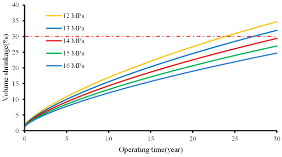
Figure 7.
Volume shrinkage rate versus operating time under different minimum internal gas pressures.
In Figure 8, the displacement at the roof decreases with the increase in the internal gas pressure and increases with the operating time. After operating for 30 years, the roof displacement is 4.02 m under 12 MPa and 2.71 m under 16 MPa, with a reduction of 32.59%. Under the same internal gas pressure, the increase rate of the roof displacement reduces gradually with the increase in the operating time. The settlement of 14 MPa after operating for 30 years is 2.2% of the height of the cavern. The roof settlement is very important to the safety of salt caverns. Many accidents are related to a big subsidence of the roof in salt cavern UGS [43]. Due to rock salt creep, the subsidence of the roof will occur with the increase in the operation time under differential stress. A certain amount of sinking is allowable if no fracture, collapse at the roof or failure at the casing shoe is produced. Therefore, the displacement must be strictly controlled to avoid excessive deformation and accidents. The settlement of the roof is not only related to the minimum internal gas pressure but also to the thickness of the rock salt roof and the location of the casing shoe. In addition, a salt cavern cannot be operated under a constant gas pressure for the whole working time. Under a cyclic loading, the displacement has a greater reduction compared with that under a fixed pressure.

Figure 8.
Z-displacement versus internal gas pressure at different operating times.
3.2. Upper Shape of Cavern
In this section, the cavern upper shape of three types with 40 m, 70 m and 100 m is investigated in the numerical simulation to optimize the salt cavern structure. The internal gas pressure of 14 MPa is applied to the wall of the cavern during the analysis. From the results of the simulation, Figure 9 presents the displacement contours of the cavern with different upper shapes after operating for 30 years under the internal gas pressure of 14 MPa. The figure on the right is the section of the neutral plane of the left picture that shows the displacement contour of the vertical section in the direction of the horizontal short axis. The displacement in this part indicates the vector sum of three displacements along the x, y and z directions. As shown in Figure 9, the maximum displacement region appears in the lower part of the effective cavity volume. The cavity with the top of 40 m has larger deformation, and the displacement of its cavern roof is larger than that of the other two cavities with their top structures of 70 m and 100 m. This may be because the 40 m top structure has a large top span with greater creep deformation under stress concentration during working conditions. The space at the bottom of the cavern filled by insolubles has a relatively small displacement, mainly because it has self-weight and a good bottom shape that can neutralize part of the unbalanced stress, and its deformation should be ignored in the whole stability analysis. The displacement of the cavern with a top shape of 100 m is the smallest among these three cavern structures, but the effective volume accessible to gas is the least as well. Therefore, the upper shape of the cavern in Pingdingshan UGS with a value of 70 m is suggested from the viewpoint of displacement and effective gas volume.
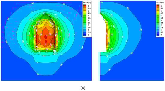
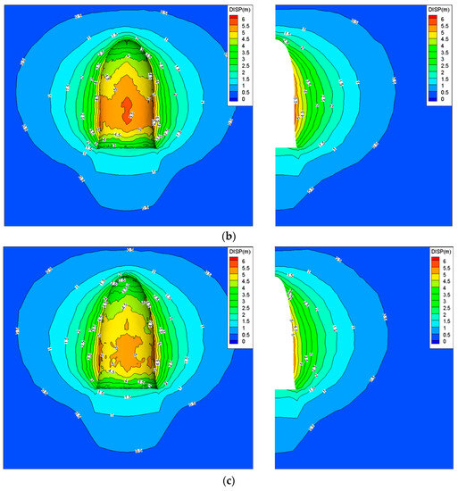
Figure 9.
Displacement contours of the caverns with different upper shapes after operating for 30 years with an internal gas pressure of 14MPa. The right picture is a section of the center plane about the left picture. (a) 40 m, (b) 70 m, (c) 100 m.
Figure 10 shows the equivalent strain contours of the caverns with different upper shapes after operating for 30 years calculated by using Equation (4). The red zone indicates the locations where the equivalent strain exceeds the critical value of 3%. That means failure easily happens at these zones. The high equivalent strain zones are mainly located near the interlayers and at the cavern roof. The property difference between the rock salt and interlayer at the interface is the main reason for the large equivalent strain. This phenomenon has been observed in many studies [44]. After excavation, the stress concentration appears in the surrounding rock of the cavern wall, which is more obvious at the cavity roof. That is why the large equivalent strain also happens at that location. The equivalent strains at the bottom of the cavern filled by insolubles are still not obvious, similar to their displacement. The red zone of the cavern is different among the three top shapes. There are more red areas in the cavern with the upper part of 40 m than that of 70 m and 100 m, especially at the roof. Therefore, a cavern with the upper shape of 70 m is suitable for Pingdingshan UGS based on the equivalent strain and effective volume.
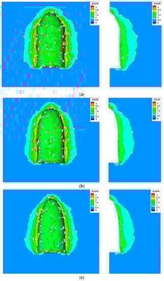
Figure 10.
Equivalent strain contours of the cavern with different upper shapes after operating for 30 years under internal gas pressure of 14 MPa. (a) 40 m, (b) 70 m, (c) 100 m.
Figure 11 presents the plastic zone contours obtained by using the Mohr–Coulomb criterion after operating for 30 years with different upper shapes under an internal gas pressure of 14 MPa. The red zones indicate the plastic failure happens at these areas. The plastic zones are mainly located at the interlayers and the cavity bottom. As the creep rate of rock salt is larger than that of the mudstone intercalation, the stress incompatibility tends to occur at the interface and causes tensile or shear failure of the interface and nearby the rock. The property difference between the rock salt and interbed is the main cause for the plastic zones at the interlayers. Considering that the insolubles consist of rock fragments and liquid mud, their mechanical parameters are assumed to be 10% of those of interlayers during the numerical simulations. This leads to the plastic zone being easier to obtain in the sediment than in the other location. However, it is meaningless to consider the plastic zone of the insolubles due to their actual state, and it should be not focused on during the safety evaluation of UGS. In addition, the plastic zone in the long axis direction is larger than that in the short axis direction. The reason is the same as that for wellbore collapse caused by excessive stress concentration in the oil drilling industry. That is to say, the unbalanced stress in the long axis direction is larger than that in the short axis direction, which results in the obvious stress concentration in the long axis direction, and shear failure more easily occurs in this direction. As it can be seen from Figure 9, the plastic zone of the cavern with the upper part of 40 m is larger than that of 70 m and 100 m. This indicates the cavern with the top structure of 40 m is easily subjected to plastic failure. From this viewpoint, this type of the cavern is not suggested for Pingdingshan UGS.
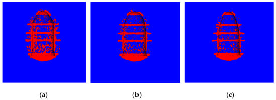
Figure 11.
Plastic zone contours of the cavern with different upper shapes after operating for 30 years under the internal gas pressure of 14 MPa. (a) 40 m, (b) 70 m, (c) 100 m.
Table 2 lists the volume shrinkage of the cavern with different upper shapes at different working times. The volume shrinkage of the three caverns increases nonlinearly with time and shows a similar change that a fast increase appears at the beginning and then the increase rate tends to stabilize with increasing time. After operating for 30 years, the volume loss rates of 31.20%, 29.34% and 28.13% are obtained for these three caverns under the internal gas pressure of 14 MPa. According to the safety evaluation, the volume shrinkage of the cavern with the upper part of 40 m exceeds 30% after 30 years and shows a large volume loss. This indicates the cavern with the upper shape of 40 m has the risk of instability, and it is not suggested for use in Pingdingshan UGS.
Table 2.
Volume shrinkage of the cavern with different upper shapes at different working times under the internal gas pressure of 14 MPa.
Above all, combined with displacement, equivalent strain, plastic zone, volume shrinkage and effective volume, the cavern with the upper part of 70 m is suggested for Pingdingshan salt cavern UGS.
3.3. Effect of RLS of Horizontal Section
Based on the physical model experiment of two-well cavern construction, the SSTW cavern presents an ellipsoidal transverse section. The cavern shape differs with the change in design parameters, such as well spacing and stage duration. The longer the distance between two wells, the larger the cavity volume, but the flatter the transverse section. The horizontal section of the cavern with a too large RLS has the risk of instability. In addition, it is not good to use a too small space between two boreholes because it will produce a small cavity volume and the cavern shape will be similar to that of an SW cavern, which is neither efficient nor economical for the cavern construction. Therefore, it is necessary to analyze the effect of the ratio of the long axis to short axis to optimize the salt cavern. According to the results of the previous section, the cavern with the top shape of 70 m is adopted in this section.
Figure 12 shows the displacement contours in the Z direction with different well spacings after operating for 30 years under an internal gas pressure of 14 MPa. In Figure 13, the cavern roof subsidence increases with well spacing. The increase rate is not constant but increases with the distance between the two boreholes. This may be because a large well spacing leads to a large roof span and a large flatness of the transverse section, resulting in the deterioration of the stress state at the top of the cavity and a large displacement produced under stress concentration. For security, caverns with a greater well spacing are suggested to increase the minimum internal gas pressure during the working time, or one can adopt a thicker roof rock salt thickness.
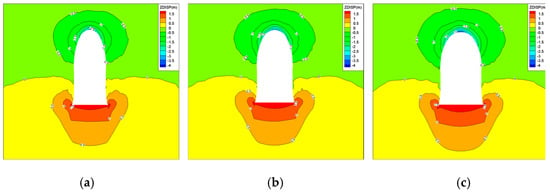
Figure 12.
Displacement contours in Z direction with different well spacings after operating for 30 years under an internal gas pressure of 14 MPa. (a) 10 m, (b) 20 m, (c) 30 m.
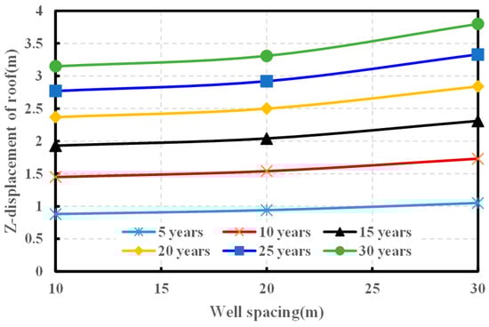
Figure 13.
Z-displacement of cavern roof with different well spacings at different operating times.
Figure 14 presents the displacement contours in the X direction with different well spacings after operating for 30 years under an internal gas pressure of 14 MPa. Figure 15 shows the X-displacement curves of the cavern waist with different well spacings at different times. The X direction of the 3D geomechanical model is in the long axis direction of the cavern, and the Y direction is in the short axis direction of the cavern. It can be seen that the Y-displacement of the waist (Figure 16) increases with the well spacing, but the X-displacement of the waist has an opposite tendency. A similar phenomenon was also observed in the stability study of SSTW salt cavern gas storage in a shallow formation in [35]. After 30 years of operation, the displacement in the Y direction is 5.55 m, 5.84 m and 6.01 m, respectively, when the well spacing varies from 10 to 30 m. As the well spacing increases, the transverse section of the cavern becomes flatter, and more loads are applied to the rock wall in the short axis direction. Moreover, the in situ stresses in the two horizontal directions are equal to each other at the same depth. That means the displacement in the Y direction is larger than that in the X direction with the same well spacing under the creep deformation of surrounding rock of the cavern. This phenomenon indicates that a larger pillar width should be designed in the short axis compared to that in the long axis when the salt cavern group is to be constructed.
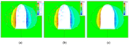
Figure 14.
Displacement contours in X direction with different well spacings after operating for 30 years under an internal gas pressure of 14 MPa. (a) 10 m, (b) 20 m, (c) 30 m.
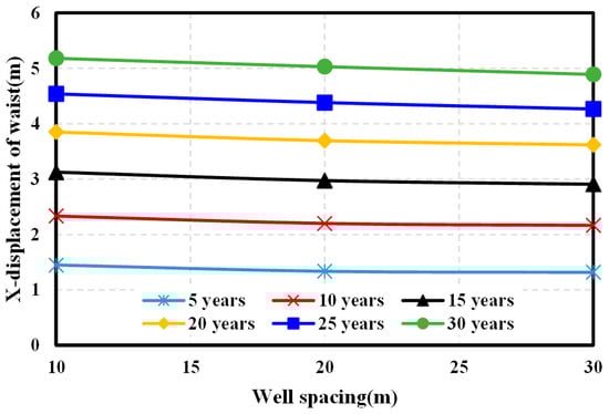
Figure 15.
X-displacement of cavern waist with different well spacings at different operating times.
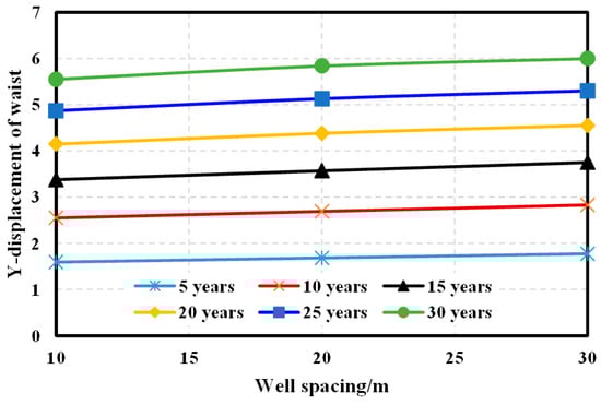
Figure 16.
Y-displacement of cavern waist with different well spacings at different operating times.
Figure 17 shows the volume shrinkage rate of three caverns with different well spacings. These curves present the same tendency under different operating times. As the space between two boreholes increases, the volume loss rate of the three caverns has a small increase. When the well spacing varies from 10 to 30 m, the volume shrinkage rate changes from 28.64% to 30.10%. From the viewpoint of the volume shrinkage rate, the well spacing has a slight effect on the stability of SSTW.
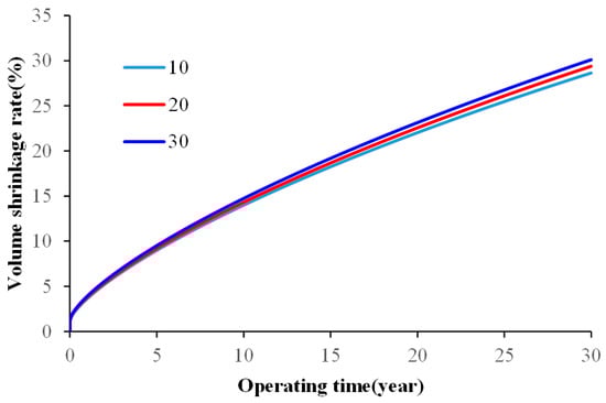
Figure 17.
Volume shrinkage rate of three caverns with different well spacings.
In Figure 18, the dilatancy safety factor is calculated by Equation (3). The red zones indicate the rock mass is in failure. The yellow areas indicate the rock mass is in local damage. It can be seen that the zones with a low safety factor are mainly present at the interlayers and insolubles. The low safety factor at the interlayers is mainly caused by the property difference between rock salt and the mudstone interlayer. This is consistent with the results obtained in the literature [45]. However, the safety factor at the insolubles is not paid attention to for the same reasons discussed above in the Section 3.1. There are slight differences in the distribution of safety factors among the three cavities. In the short axis direction, the distribution areas of a low safety factor in the cavity with a well spacing of 30 m are slightly larger than those in the other cavities with a well spacing of 10 m and 20 m. After operating for 30 years, the safety factor at the cavern roof with a well spacing of 10 m, 20 m and 30 m is 1.86, 1.55 and 1.43, respectively. This indicates the roof of the cavern with a well distance of 30 m is easier to get into a risk of instability when operating for a long time. From the viewpoint of the safety factor, the well spacing of 20 m is suggested for Pingdingshan SSTW. Of course, the effect of more precise well spacing needs to be further studied.
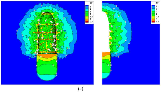
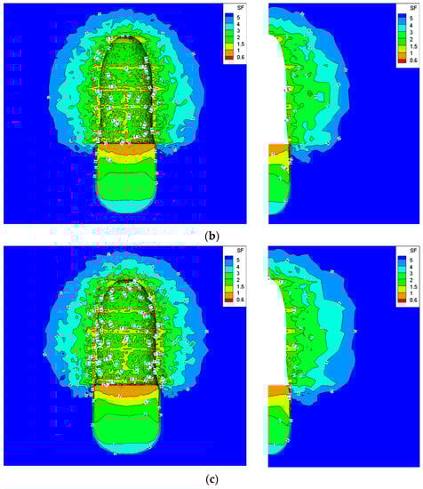
Figure 18.
Dilatancy safety factor contours of the caverns with different well spacings after operating for 30 years under the internal gas pressure of 14 MPa. (a) 10 m, (b) 20 m, (c) 30 m.
Figure 19 presents the equivalent strain of the cavern roof with different well spacings at different times. All values are obtained under the internal gas pressure of 14 MPa. It can be seen that the ES changes with increasing well spacing. When the well distance varies from 10 to 30 m, the ES at the cavern roof is 2.36%, 2.80% and 3.23%, respectively, after operating for 30 years. The ES of the cavern roof with a well spacing of 30 m exceeds 3%, which indicates this kind of cavern has a risk of instability.
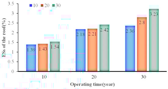
Figure 19.
Equivalent strain of the cavern roof with different well spacings at different times.
Figure 20 shows the plastic zone volume variation of the cavern with different well spacings after operating for 30 years under an internal gas pressure of 14 MPa. It can be seen that the plastic zone volume increases with the operating time. This is because the phenomenon of stress incompatibility at the interface between the interlayer and rock salt is more obvious with the shrinkage of the cavern. More tensile or shear failure will occur in the interlayer or adjacent rock with the increase in the operating time that enlarges the volume of the plastic zone. In Figure 20, the ratio of the plastic zone volume to the initial cavern volume increases with the well spacing. However, the change in this ratio is small. Only about 1.5% of increase occurs from 10 to 30 m of the well spacing after 30 years’ operation. Therefore, the space between two boreholes has a slight effect on the plastic zone of the salt cavern UGS.
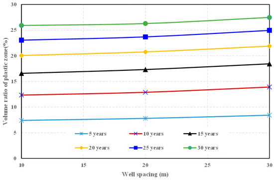
Figure 20.
Ratio of plastic zone volume to initial cavern volume with different well spacings after operating for 30 years.
4. Discussion of Results
- (1)
- Through the numerical simulation results, the internal gas pressure of no less than 14 MPa is suitable for Pingdingshan salt cavern UGS based on the volume shrinkage and roof subsidence. Similar research methods have been used in the literature [11,35,36]. The minimum internal gas pressure of Pingdignshan UGS is higher than that of Jintan salt cavern because the depth of its cavity is larger and suffers greater geostress. The same phenomena are observed in Huai’an gas storage and Qianjiang gas storage in China [45,46]. However, it must be acknowledged that the internal gas pressures obtained from simulation results are relatively conservative as they increase gradually over time due to cavern shrinkage caused by creep. Moreover, in actual engineering, the UGS generally operates under cyclic internal pressure rather than constant pressure. Therefore, as a reference, it is feasible to slightly reduce the certain internal pressure for operation in practical engineering, but it cannot be maintained for a long time. The reduced pressure can be determined by stability analysis under cyclic internal pressure operation.
- (2)
- The shape of the cavity is very important for the long-term operation safety of the UGS. The research from [45] indicates that it is feasible to build a cylindrical cavity by the SW mining method in strata with a depth of more than 1900 m. In addition, a pear-shaped cavern was demonstrated to have a fairly good stability in a single-well salt cavern UGS [47]. The three kinds of roof shape of the cavities designed in this paper are based on design experience of single-well cavities. The numerical results show the salt cavern with an upper height of 70 m has a good stability in such ultra-deep formation according to the evaluation of displacement, safety factor, volume shrinkage and effective volume. This indicates that it is feasible to build an SSTW salt cavern for an ultra-deep formation from the viewpoint of stability.
- (3)
- Well spacing influences the flatness of the salt cavern transverse section. At present, there are few research works on the well spacing of SSTW salt caverns. The results in this paper show that the RLS has a slight effect on the stability of the cavern by the ways of volume shrinkage and roof subsidence, which is consistent with the results of [35]. A larger well spacing can obtain a larger gas storage volume. However, when the distance exceeds 30 m, both the safety factor and effective strain of the cavity roof exceed the threshold. That means the cavity suffers a risk of instability. The reason for this phenomenon is that a larger well spacing produces a flatter roof shape, which results in a greater stress concentration at the cavern roof and causes its property deterioration. Therefore, on the premise of obtaining a larger gas storage volume, it is suggested that the well spacing of SSTW salt cavern UGS should not exceed 30 m.
5. Conclusions and Suggestions
Benefiting from their good performance, double-well salt caverns with a small well spacing have an extensive application prospect in bedded salt formations in China. Based on the geomechanical features of Pingdingshan salt mine, a 3D visco-elastic-plastic model was established to investigate the influence of the minimum internal gas pressure, cavern upper shape and well spacing on the safety of SSTW salt cavern gas storage. An evaluation index system composed of displacement, plastic zone, dilatancy safety factor, volume shrinkage and equivalent strain was introduced for the safety and parameter optimization of two-well salt cavern UGS. The main results show the following:
- (1)
- The mudstone interlayer in Pingdingshan salt mine belongs to a hard intercalation, which has a higher strength and weaker deformation than those of rock salt. The creep deformation of rock salt is relatively large, and it still does not enter the accelerated creep stage when the stress difference is up to 30 MPa. The creep mode of rock salt from Pingdingshan salt mine conforms to the Norton Power model.
- (2)
- The minimum internal gas pressure of Pingdingshan UGS should not be less than 14 MPa under long-term constant pressure operation based on the evaluation of the volume loss rate and roof subsidence. Considering the injection–production circulation and the internal pressure increasing over time due to the cavity convergence, the minimum gas pressure can be reduced properly to obtain higher gas storage efficiency.
- (3)
- The roof shape of the salt cavern has a larger influence on the stability of UGS. Under the same diameter and cavity height, a smaller cavern upper height can obtain a larger gas storage volume, while the safety of the roof tends to deteriorate. The salt cavern with an upper height of 70 m meets the requirements of safety assessment and large volume, and thus it is recommended for Pingdingshan salt cavern gas storage.
- (4)
- When the length of the short axis direction of the cavern transverse section is fixed, the effective volume of the salt cavern increases with the well spacing. The change in the RLS has a slight effect on the stability of UGS. From the viewpoint of the threshold of each assessment index, the well spacing should not exceed 30 m for the safety of the salt cavern. Among the values of 10 m, 20 m and 30 m, the well spacing is recommended to be 20 m for Pingdingshan gas storage. When the cavern groups are constructed, the pillar width on the short axis should be lengthened because of the larger displacement than that on the long axis.
Overall, SSTW salt caverns have good feasibility for the construction of UGS in ultra-deep formations. In the view of safety, the roof span of the SSTW cavity should not be too large to avoid its collapse and excessive subsidence. The optimal well spacing and roof shape need to be refined through research in the future to obtain the maximum storage volume and sufficient safety.
Author Contributions
Conceptualization, H.L. and J.D.; methodology, H.L. and Y.F.; software and investigation, H.L. and Y.F.; resources and data curation, Q.W. and C.L.; writing—original draft preparation, H.L. and A.R.K.L.; writing—review and editing, A.R.K.L. and C.H.; visualization, Q.W. and C.L.; supervision, J.D. All authors have read and agreed to the published version of the manuscript.
Funding
This research was funded by National Natural Science Foundation of China, grant number No52074312.
Institutional Review Board Statement
Not applicable.
Informed Consent Statement
Not applicable.
Data Availability Statement
The study did not report any data.
Acknowledgments
This research would like to thanks to Professor Vamegh Rasouli of Department of Petroleum Engineering from University of North Dakota for his constructive suggestions and modifications.
Conflicts of Interest
The authors declare no conflict of interest.
References
- Bérest, P.; Bergues, J.; Brouard, B. Review of static and dynamic compressibility issues relating to deep underground salt caverns. Int. J. Rock Mech. Min. Sci. 1999, 36, 1031–1049. [Google Scholar] [CrossRef]
- Bérest, P.; Brouard, B. Safety of salt caverns used for underground storage. Oil Gas Sci. Technol. 2003, 58, 361–384. [Google Scholar] [CrossRef]
- Wang, T.T.; Yan, X.Z.; Yang, H.L.; Yang, X.J. Stability analysis of the pillars between bedded salt cavern groups by cusp catastrophe model. Sci. China Tech. Sci. 2011, 54, 1615–1623. [Google Scholar] [CrossRef]
- Lim, J.W.; Lee, E.; Moon, H.S. Integrated investigation of seawater intrusion around oil storage caverns in a coastal fractured aquifer using hydrogeochemical and isotopic data. J. Hydrol. 2013, 486, 202–210. [Google Scholar] [CrossRef]
- Zhao, Z.C. Theory of Fluid Transportation and Configuration Development in Solution Mining Cavern for Underground Gas Storage. Ph.D. Thesis, Graduate University of Chinese Academy of Sciences, Wuhan, China, 2003. [Google Scholar]
- Liang, W.; Yang, C.; Zhao, Y.; Dusseault, M.B.; Liu, J. Experimental investigation of mechanical properties of bedded salt rock. Int. J. Rock Mech. Min. Sci. 2007, 44, 400–411. [Google Scholar] [CrossRef]
- Chen, W.Z.; Wang, Z.C.; Wu, G.J. Nonlinear creep damage constitutive model of rock salt and its application to engineering. Chin. J. Rock Mech. Eng. 2007, 26, 467–472. [Google Scholar]
- Zheng, Y.; Zhao, Y.J. General situation of salt cavern storage worldwide. Oil Gas Storage Transp. 2010, 29, 652–655, 663. [Google Scholar]
- Ozarslan, A. Large-scale hydrogen energy storage in salt caverns. Int. J. Hydrog. Energy 2012, 37, 14265–14277. [Google Scholar] [CrossRef]
- Wang, G.; Guo, K.; Christianson, M.; Konietzky, H. Deformation characteristics of rock salt with mudstone interbeds surrounding gas and oil storage cavern. Int. J. Rock Mech. Min. Sci. 2011, 48, 871–877. [Google Scholar] [CrossRef]
- Ma, H.L.; Yang, C.H.; Qi, Z.X.; Li, Y.F.; Hao, R. Experimental and numerical analysis of salt cavern convergence in ultra-deep bedded formation. In Proceedings of the 46th U.S. Rock Mechanics/Geomechanics Symposium, Chicago, IL, USA, 24–27 June 2012. [Google Scholar]
- Yang, C.H.; Wang, T.T.; Li, Y.P.; Yang, Y. Feasibility analysis of using abandoned salt caverns for large-scale underground energy storage in China. Appl. Energy 2015, 137, 467–481. [Google Scholar] [CrossRef]
- Yang, C.H.; Li, Y.P.; Qu, D.A.; Chen, F.; Yin, X.Y. Advances in researches of the mechanical behaviors of bedded salt rocks. Adv. Mech. 2008, 38, 484–494. [Google Scholar]
- Wang, A.M.; Yang, C.H.; Chen, J.W.; Huang, Z.Q.; Li, Y.P. Nonlinear creep constitutive model of bedded salt rock. Chin. J. Rock Mech. Eng. 2009, 28, 2708–2714. [Google Scholar]
- Ren, T. Study on the Effect of Interlayer Occurrence Characters on the Mechanical Properties of Molded Layered Salt Rock and the Long-Time Stability of Storage. Ph.D. Thesis, University of Chongqing, Chongqing, China, 2012. [Google Scholar]
- Giouse, C.H. Report of working committee 2: Underground gas storage. In Proceedings of the 25th World Gas Conference, Kuala Lumpur, Malaysia, 4–8 June 2012. [Google Scholar]
- Ran, L.N.; Zheng, D.W.; Ha, B.J.; Wang, Y.; Gou, Y.X. Overview and development of energy storage using salt caverns in the world. In Proceedings of the National Natural Gas Symposium, San Antonio, TX, USA, 2–6 June 2019; pp. 440–445. [Google Scholar]
- Kazemi, H.; Jessen, F.W. Mechanism of flow and controlled dissolution of salt in solution mining. SPE J. 1964, 4, 317–329. [Google Scholar] [CrossRef]
- Sears, G.F.; Jessen, F. Controlled solution mining in massive salt. SPE J. 1966, 6, 110–125. [Google Scholar] [CrossRef]
- Nolen, J.S.; Hantlemann, G.V.; Meister, S. Numerical simulation of the solution mining process. Presented at the SPE European Spring Meeting, Amsterdam, The Netherlands, 29–30 May 1974. [Google Scholar] [CrossRef]
- Li, Y.P.; Liu, J.; Yang, C.H. Influence of mudstone interlayer on deformation failure characteristics of salt rock. Chin. J. Rock Mech. Eng. 2006, 25, 202–210. [Google Scholar]
- Yu, L.; Liu, J. Stability of interbed for salt cavern gas storage in solution mining considering cusp displacement catastrophe theory. Petroleum 2015, 1, 82–90. [Google Scholar] [CrossRef]
- Shi, X.L.; Li, Y.P.; Yang, C.H.; Qu, D.A. Test study of influence of brine on tensile strength of muddy intercalation. Chin. J. Rock Mech. Eng. 2009, 28, 2301–2308. [Google Scholar]
- Shi, X.L.; Li, Y.P.; Yang, C.H. Collapse control technology for interbeds in solution mining for oil/gas storage in multi-interbedded salt formation. Chin. J. Rock Mech. Eng. 2011, 33, 1957–1963. [Google Scholar]
- Qu, D.A. Research on the Mechanism of Interlayer Collapse Prediction and Control in the Process of Bedded Salt Rock Building Cavern. Ph.D. Thesis, University of Chongqing, Chongqing, China, 2013. [Google Scholar]
- Wang, Y.G.; Chen, J.S.; Liu, C.; Li, J.J. The technology for controlling the collapse of thick interlayer during the construction of salt-cavern gas storage. Oil Gas Storage Transp. 2017, 38, 1035–1041. [Google Scholar]
- Zheng, Y.L.; Zhao, Y.J.; Ding, G.S. Solution mining technology of enlarging space for thick-sandwich salt cavern storage. Pet. Explor. Dev. 2017, 44, 137–144. [Google Scholar] [CrossRef]
- Liu, W.; Li, Y.P.; Yang, C.H.; Ma, H.J. Investigation on permeable characteristics and tightness evaluation of typical interlayers of energy storage caverns in bedded salt rock formations. Chin. J. Rock Mech. Eng. 2014, 33, 500–506. [Google Scholar]
- Tang, M.M.; Wang, Z.Y.; Ding, G.S. Experimental study of full process of strain of rock salt and salt-mudstone interlayer in huai’an salt mine. Chin. J. Rock Mech. Eng. 2010, 29, 2712–2719. [Google Scholar]
- Li, Q. Research on the Long Term Stability of Underground Gas Storage in Bedded Salt Formation. Master’s Thesis, Southwest Petroleum University, Chengdu, China, 2017. [Google Scholar]
- Jiang, D.Y.; Li, X.K.; Li, X.J. Flow field physical experiment of twin-well of small spacing vast cavity and its numerical calculation. Adv. Eng. Sci. 2017, 49, 65–72. [Google Scholar]
- Ren, S.; Tang, K.; Yi, L.; Liu, W. Properties of Two-Well Dissolution Cavity-Building Expansion with Small Well Space. J. Northeast. Univ. Nat. Sci. 2017, 38, 1654–1658. [Google Scholar]
- Ren, S.; Tang, K.; Yi, L.; Chen, J.; Liu, W. Research on two-well solution mining cavity expansion with small well space. Chin. J. Undergr. Space Eng. 2018, 14, 805–812, 858. [Google Scholar]
- Yi, L.; Jiang, D.Y.; Chen, J.; Liu, X.R.; Tang, H.J. Research on two-well solution mining model test with small well space. Chin. J. Undergr. Space Eng. 2017, 13, 155–161, 169. [Google Scholar]
- Chen, J.; Lu, D.; Liu, W. Stability study and optimization design of small-spacing two-well (SSTW) salt caverns for natural gas storages. J. Energy Storage 2020, 27, 1–11. [Google Scholar] [CrossRef]
- Wang, T.T.; Yang, C.H.; Ma, H.L.; Daemen, J.J.K. Safety evaluation of gas storage caverns located close to a tectonic fault. J. Nat. Gas Sci. Eng. 2015, 23, 281–293. [Google Scholar] [CrossRef]
- Li, H.; Yang, C.H.; Huang, S.L. A power function micro-creep model of salt rock. In Proceedings of the 53rd U.S. Rock Mechanics/Geomechanics Symposium, New York, NY, USA, 23–26 June 2019. [Google Scholar]
- Dassault Systems Inc. ABAQUS Analysis User’s Manual V2016 ABAQUS; Dassault Systems Inc.: Vélizy-Villacoublay, France, 2016. [Google Scholar]
- Itasca Consulting Group Inc. FLAC3D Version 6.0 Users’ Manual; Itasca Consulting Group Inc.: Minneapolis, MN, USA, 2019. [Google Scholar]
- Tecplot Inc. Tecplot 360 EX 2015 R1 User’s Manual; Tecplot Inc.: Bellevue, WA, USA, 2015. [Google Scholar]
- Wang, T.T.; Yan, X.Z. A new shape design method of salt cavern used as underground gas storage. Appl. Energy 2013, 104, 50–61. [Google Scholar] [CrossRef]
- DeVries, K.L. Geomechanical analyses to determine the onset of dilation around natural gas storage caverns in bedded salt. In Proceedings of the SMRI Spring Technical Meeting, Brussels, Belgium, 30 April–3 May 2006. [Google Scholar]
- Jing, W.J.; Yang, C.H.; Chen, F. Risk assessment of salt cavern oil/gas storage based on accident statistical analysis. Rock Soil Mech. 2008, 32, 1787–1793. [Google Scholar]
- Wang, A.M. The Deformation Mechanism and Nonlinear Creep Constitutive Model of Bedded Salt Rock. Ph.D. Thesis, Graduate University of Chinese Academy of Sciences, Wuhan, China, 2008. [Google Scholar]
- Wang, T.T.; Ma, H.L.; Shi, X.L.; Yang, C.H. Salt cavern gas storage in an ultra-deep formation in Hubei, China. Int. J. Rock Mech. Min. Sci. 2018, 102, 57–70. [Google Scholar] [CrossRef]
- Wang, J.B. Study on the Creep Mechanical Properties of Salt Rock under Different Loading Paths and Long-Term Stability of Salt Rock Gas Storage. Ph.D. Thesis, University of Chongqing, Chongqing, China, 2012. [Google Scholar]
- Liang, G.C.; Huang, X.; Peng, X.Y. Investigation on the cavity evolution of underground salt cavern gas storages. J. Nat. Gas. Sci. Eng. 2016, 33, 118–134. [Google Scholar] [CrossRef]
Publisher’s Note: MDPI stays neutral with regard to jurisdictional claims in published maps and institutional affiliations. |
© 2021 by the authors. Licensee MDPI, Basel, Switzerland. This article is an open access article distributed under the terms and conditions of the Creative Commons Attribution (CC BY) license (https://creativecommons.org/licenses/by/4.0/).