1. Introduction
Diagnostics plays an important role in the operation of power transformers. It is based on many methods that, when properly applied, comprehensively define the technical condition of a given unit, especially in relation to their larger population; and, in combination with economic tools, they decide on planning for the future operation, renovation or replacement of a transformer. The correct approach to diagnostic issues is of fundamental importance in the current models of grid asset management, especially when limiting investment expenditure, with the simultaneous increase in the average age of the transformers in use and practically no prospects of the quick replacement with a new one, both for financial reasons and due to the production capacity of the plants producing transformers [
1,
2].
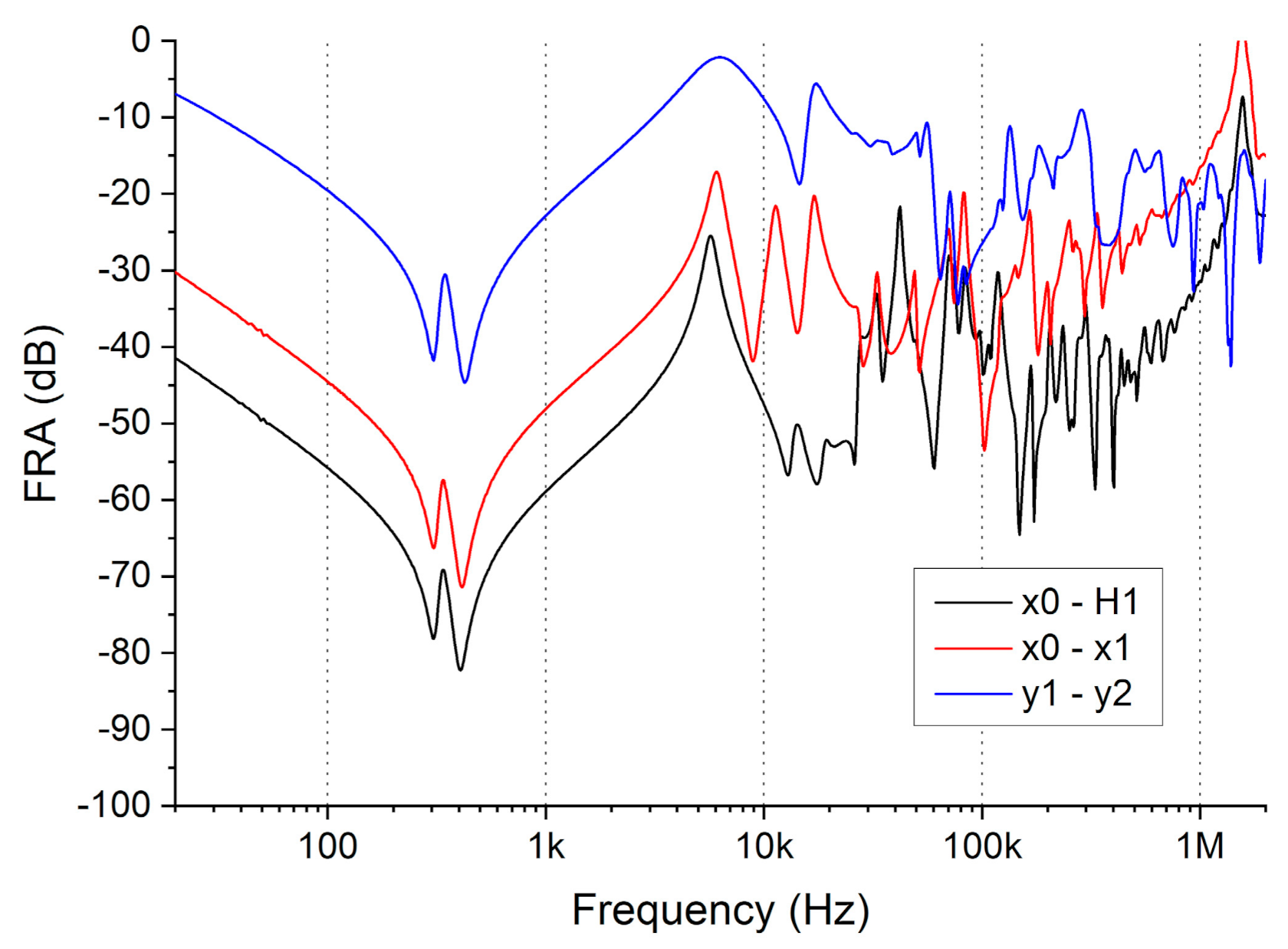
One of the causes of transformer failure lies in the mechanical deformations of the windings, usually due to large electrodynamic forces resulting from short-circuits. The diagnostics of the mechanical condition of a transformer’s active part is, at present, based on Frequency Response Analysis (FRA). At the present time, commercial recorder solutions are available, the measurement technique has been mastered, development work on the methods for interpreting the result is also progressing, and attempts have been made to standardize it all [
3,
4]. FRA allows determination of the mechanical conditions of the windings, their displacements, deformations and electric faults, as well as some of the problems with internal leads and connections, core and bushings. The transformer winding can be described by a set of local capacitances, self- and mutual inductances and resistances. Every change in winding geometry leads to a change in these parameters, which influences the shape of the transfer function. The analysis of frequency response measurement results is based on comparison of the data, which are usually presented as sine signal damping along the frequency spectrum in a logarithmic scale. Such a curve can be compared to the results recorded for a transformer in time intervals, between phases, between twin or sister units or with the help of computer models [
5]. However, there are still many problems with interpreting the test results in cases where the compared curves are not similar. Due to an insufficient number of verified measurements on units with known deformations, it is hard to determine if and what problem exists in the winding. A helpful tool may be computer modelling of the Frequency Response (FR). After obtaining a model giving similar results to a real object, it is possible to introduce forced deformations and find out their effects on the FR curve [
6].
The paper is divided into eight sections.
Section 2 provides a thorough review of modelling techniques on the basis of literature review. Described methods are then presented in following Sections, with examples presented by authors and supported with results coming from other papers.
Section 3 contains description of the simple approach to frequency response modelling, based on lumped parameter models, which are solved in standard circuit simulators. In
Section 4, the lumped parameter approach was modified with input data obtained from FEM modelling, which allowed the model discretization to increase.
Section 5 takes under consideration wave effects in windings. In
Section 6, the influence of the other windings installed on the same core on the model and a method for simulating them are described, while in
Section 7 a model of windings connected in parallel is given, which is important in the case of many power transformers having such connection of wires in their windings. The last section is the Summary and Future Work.
2. Transformer Modelling
Transformer models have been developed for years, finding many applications. They are used to determine the behavior of transformers under surge conditions and to interact with the power system or to analyze the frequency response used in diagnostics. In practice, there are many methods of modelling. The easiest and most accurate modelling is based on transformer design data, but this is usually not available for in-service transformers, which makes it difficult to develop models consistent with the behavior of the actual object.
The first models, taking into account the behavior of the transformer at frequencies other than operating ones, were made at the beginning of the 20th century in order to analyze the capacitive behavior of the system under impulse conditions [
7]. Since then, new modelling methods have been implemented, depending on the tasks set for the models. With the evolution of computer techniques, modelling methods have been developed based on the possibility of solving more and more complex systems and taking into account subsequent phenomena [
6]. The undoubted advantage of the models is the ability to learn about the behavior of very complex systems without the need to conduct risky experiments or incur high costs.
The oldest method of modelling the frequency response of transformers is the use of analytical methods, which, of course, have numerous limitations, especially when accurate modelling of real objects is needed. Therefore, new methods are constantly introduced and developed. Many literature reviews collecting modelling methodology can be found, including in E. Bjerkan’s doctoral dissertation [
6] or publication [
8]. These methods can be divided according to the nature of the calculated parameters: inductance, capacitance and losses.
One of the first methods of calculating inductance was the introduction of a ladder system taking into account self- and mutual inductances, the foundations of which were developed 100 years ago [
9]. The method was developed using computers [
10] and by taking into account subsequent phenomena occurring in the active part of the transformer [
11]. Further modifications consisted of taking into account the influence of the core and losses in the windings [
12,
13], thanks to which the calculations for the self- and mutual inductances of windings and their fragments were very consistent with the actual values. The inductance values for the low-frequency ranges for individual coils reached very similar values, which resulted in the formation of poorly conditioned matrices and equations. This problem was solved by introducing modelling methods based on leakage inductance or on the principle of duality. The first method was developed in 1919 [
14,
15,
16,
17] and is currently used to calculate the leakage inductance of transformers at low frequencies based on the short-circuit nominal data. This method does not fully take into account the influence of the core. On the other hand, modelling based on the principle of duality allows for the correct modelling of the core at low frequencies using the equivalent circuit related to the reluctance of the core [
18]. However, the leakage inductances are then obtained directly from the leakage flux, disregarding the thickness of the windings. Attempts were made to correct this problem by assuming the axial direction of the magnetic field or by using the model for conditions of high core saturation [
19]. Due to the limitations related to leakage flux, this method enables modelling at low and medium frequencies (in accordance with the frequency division criteria introduced in the FRA method) [
20]. The authors of [
21] propose expression of the transformer’s transfer function electrical equivalent model based on parallel RLC cells.
The next step in the modelling techniques was to take into account the wave phenomena in the winding and treat it as a long transmission line—Transmission Line Model (TLM). Such models were proposed by Wagner [
22] in 1915, after which they were developed, e.g., by jointly applying models based on a single long line Single Transmission Line (STL) and a multiple long line MTL (Multi-Transmission Line) [
23]. These methods are being developed to this day; e.g., in [
24] an MTL model for the coil winding was proposed, taking into account the travelling wave theory. In a number of publications, this subject is also developed by de Gersem [
25,
26] and other authors [
27]. A comparison of the efficiency of modelling a winding’s deformations with two approaches—an equivalent circuit model based on inter-turn and inter-disc parameters and a multi-conductor transmission line model—is presented in [
28]. It was proved that both methods can give comparable results.
Another method of modelling is to consider only the outputs of the system—i.e., treating the whole as a so-called black box. The content of the black box is then synthesized from the measured data. This method does not refer to the real geometry of the modelled object, so it cannot be used to determine the influence of specific deformations on changes in the frequency response. However, it enables the creation of models based on measurement data [
29,
30,
31], both in the time and frequency domains. The models obtained in this way cannot, of course, be generalized for the entire population of transformers, although some common features can be distinguished depending on the design or size of the transformer. The basic tools used to create models based on measurements are modal analysis [
32,
33,
34], representation with poles and zeros [
35] and representation with vectors [
30]. The mathematical relationships of power transformer models based on the “black box” principle are described in [
36].
The discussed methods are often used together—for example, combined methods of analysis of the dissipation inductance and the principle of duality [
37]. Another approach uses the calculation of self- and mutual inductances in conjunction with the black box method, which improves the compatibility of the models with measurements in the higher frequency ranges [
38].
The calculations for capacitance, such as inductance, can be performed in the simplest way for analysis from known formulas or using computers and methods based on the actual geometry of the system and its material properties [
39]. The series capacitances in the models correspond to the capacities between the turns of a given winding and determine the electrostatic voltage distribution between them. Various methods are used for these calculations [
40,
41]. The problem becomes more complex with interlaced windings or with internal shields [
42,
43]. Parallel capacitances occur between individual windings and the ground. This should include both winding connections, bushings and tap changers. Another important problem in transformer modelling is the consideration of losses. Without taking into account their influence, the electric stresses in the model will be greater than in the real object, which will lead to errors and models that are too complicated [
44]. The occurrence of losses in the transformer is influenced by the series direct current resistance of the conductors, the skin effect at higher frequencies, the occurrence of eddy currents resulting in a reduction in the magnetic flux value [
45], the proximity effect associated with the occurrence of electromagnetic fields, the source of which is other conductors [
46], or dielectric losses in insulation resulting from the conductivity of the insulation and its polarization. The latter is usually not modelled, using, at most, estimated values for low frequencies.
The choice of the transformer modelling method depends on the purpose of the model. Models are widely used to determine the behavior of a transformer in the presence of impulse waveforms in the windings, both at the design stage and for the purposes of determining insulation coordination [
17,
47,
48]. This also applies to the transformer’s response, the voltage distribution in the windings and the electrical strength of the insulation in the event of both atmospheric [
49] and switching overvoltages [
50,
51]. The influence of the tap changer on transients may also be modelled [
52]. Another important part of transformer modelling is the analysis of magnetic parameters—for example, to calculate core losses [
53] or the magnetic flux density distribution and magnetic field energy in the transformer’s active part [
54].
In recent years, transformer modelling methods have also been used in the frequency response analysis method, which needs the compatibility of the modelled and recorded waveforms in a wide frequency range to be obtained. Therefore, such models should take into account a number of phenomena, from magnetic ones in low-frequency ranges to wave phenomena in high-frequency ranges. For low frequencies, an important issue is the correct consideration of the core, reflecting its real role in the phenomena. It is assumed that its influence can be neglected above a frequency of approx. 10 kHz [
6,
55], where it is assumed to be an ideal conductive shield. For low-frequency ranges, nonlinear phenomena such as hysteresis or core saturation should be considered. An example of a detailed analysis of 3D modelling results, taking into account the anisotropic properties of the core, is presented in [
56]. It has been shown that the core influence is noticeable in the transformer response down to 1 MHz; however, it has a significant effect up to 10 kHz. Further work by the same authors led to the development of a peripheral model taking into account the frequency-dependent features of the core and insulation materials [
57]. However, in the case of the properties of dielectrics used in the insulation of transformers and included in the models, it is usually assumed that their electrical parameters are independent of frequency, environmental factors or the degree of ageing [
6]. The importance of correct core modelling, also in the high-frequency range, is described in [
58]. A double-ladder circuit model of a transformer winding is described in [
59], which considers two branches: one for the frequency-dependent effect and the other one for core losses. Examples of high-frequency models used for the FRA method are also presented in the works of Florkowski and Furgał [
60,
61]. The method of a state space representation for power transformer high-frequency modelling may also be applied to simulate deformations in the windings [
62].
For models created on the basis of measurement results [
55], appropriately prepared algorithms are used to analyze the location of characteristic points on the frequency response curve. It is also possible to create models obtained from the measurements for a circumferential connection of parallel branches containing various combinations of R, L and C elements, and the corresponding parallel and series resonances or signal attenuation in a wider frequency range [
63]. Taking into account the differences in the system response for different frequency ranges, such modelling can be divided into sub-ranges and appropriate RLC branches can be generated for each of them [
64].
On the other hand, Mitchell and Welsh proposed models based on FRA measurement systems (between the ends of the winding, inter-winding), aimed at facilitating the analysis of measurement results in the case of differences between the measured curves. These models take into account the design of the transformer (windings, magnetic circuit) and the method of connection of the measurement system in the algorithm used to generate the results [
65,
66].
A tool that is often used to assist in modelling with various methods is analysis of the electromagnetic fields. Calculations of the field distributions are carried out, for example, for the design of transformers in order to be able to assess insulation stresses and losses related to eddy currents. Currently, such calculations are usually performed with the help of the Finite Element Method (FEM) [
67] and powerful computing servers. Sensitivity analysis can be helpful in creating such models [
68].
This paper presents a review of various modelling methods used to simulate the frequency response of transformer windings. The aim of the research and development of modelling methods was to allow analysis of the influence of deformations and faults in the windings on the changes in the frequency response. All described methods are given with examples of the modelling results performed by the authors of this paper. The simplest approach is based on lumped parameters models with input data coming from direct calculations based on the winding geometry. In the next step, the input data for such models was obtained from FEM modelling software. Another method was based on distributed parameters and consideration of the wave phenomena in the windings. The analysis was also performed for practical problems in winding modelling: the influence of windings other than the modelled one, placed on a common core, and the influence of parallel wires in a given winding, which is typical in the construction of power transformers.
3. Lumped Parameter Models Solved Using Circuit Simulators
The first models of single transformer windings and their complete structures were made by authors using the circuit method, creating meshes of RLC elements with a degree of complexity suitable for the complexity of the model, the number of modelled phenomena and the expected compliance of the model’s response with that of the real object. The values of individual elements were calculated using elementary formulas. Creating such a model with sufficient accuracy (i.e., containing many RLC elements) required a lot of computation and tedious generation of the RLC structure in the circuit analysis software.
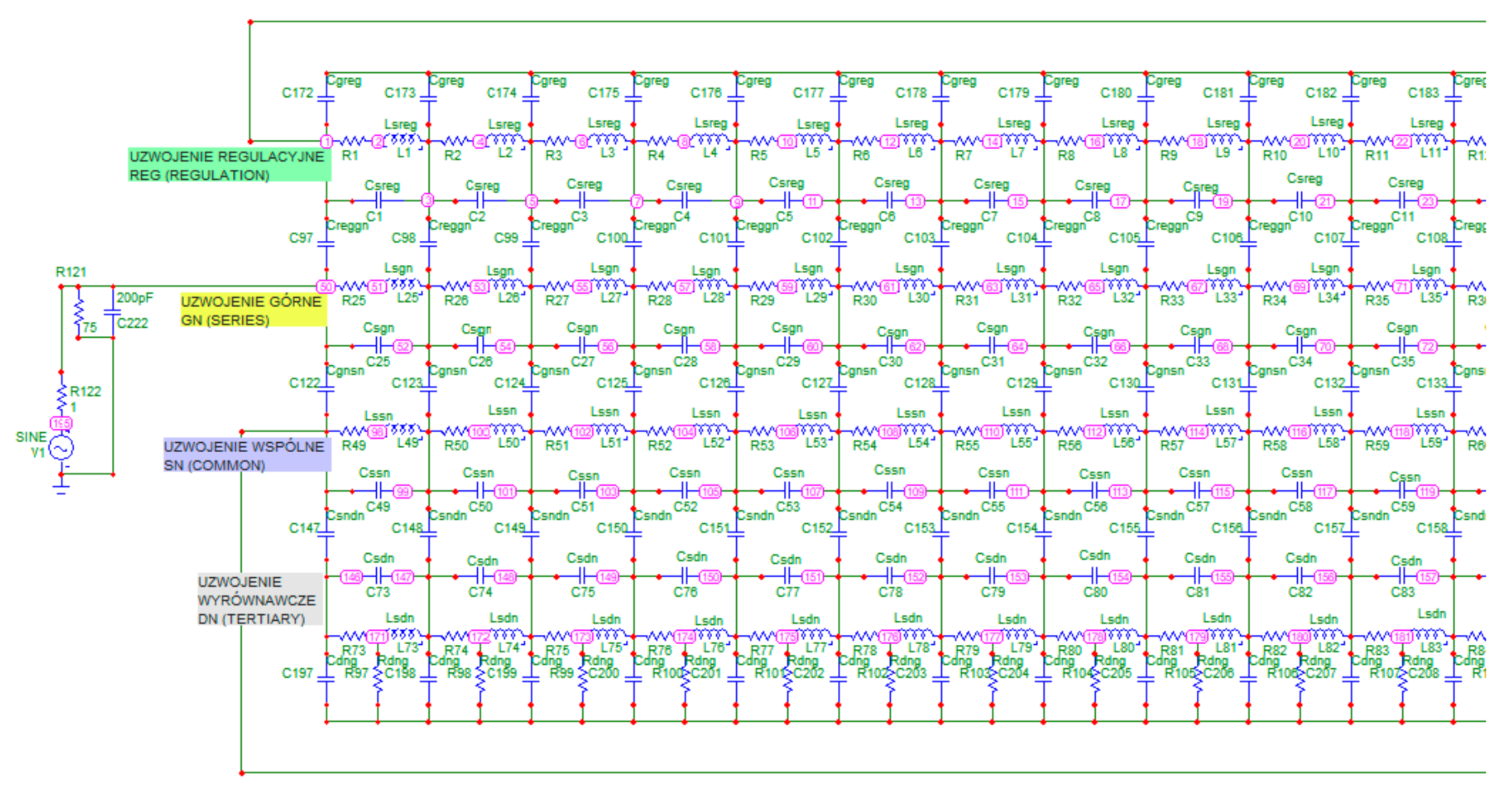
Figure 1 shows an example of a highly complex model, which, apart from the basic RLC grid, also includes magnetic couplings between adjacent inductors in the circuit. The authors’ intention was to graphically show the complexity of the model structure in the drawing, hence the illegibility of the descriptions contained therein. The coupling elements in the drawing are arranged in the shape of triangles. The presented model reflects the four windings of an autotransformer. For the purposes of the model, it was necessary to calculate the resistance of all the windings, the capacitance between the windings and their own capacitances, divided according to the number of equivalent elements, as well as the inductance and magnetic couplings [
69].
The next figure (
Figure 2) shows an enlarged fragment of this model, with the structure of the connections of the individual elements visible, which on the one hand reflect the electrical connection system in a real object, and on the other hand, the internal capacitances and inductances of the windings (series) and inter-windings (parallel). The couplings between the individual inductances of the model are also important.
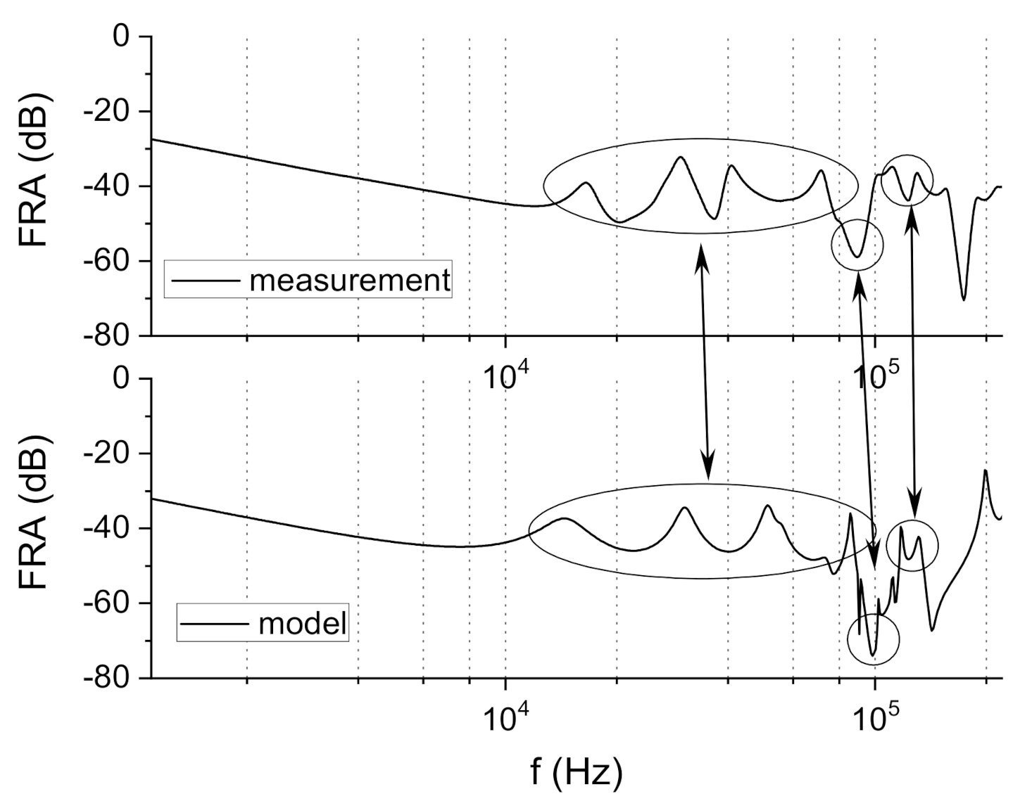
Applying the presented method created a model of the complete transformer, with voltages of 110/15 kV and a power rating of 16 MVA. The winding model was based on approximate geometrical dimensions and the winding card was not available for the tested transformer, and access to the internal windings was difficult. The model was based on ten sets of RLC elements, both series and parallel, and the corresponding magnetic couplings. It consisted of 156 R, L and C elements and over 300 magnetic couplings. The compared waveforms of the model and the real object are characterized by a similar shape; however, the exact location of the resonances on the frequency axis and their amplitude show differences, which makes their direct comparison on one graph unclear. It is presented in
Figure 3.
The presented simulations show that even a model of finite accuracy, based on the division of each winding into only ten equivalent series and parallel elements, can provide a simple model response comparable to the waveform obtained from measurements in the frequency ranges showing the deformation of transformer windings. The details of the model are given in
Table A1 in
Appendix A.
A similar approach to frequency response modelling can be found in many publications, which propose various modifications to the standard RLC models. For example, in [
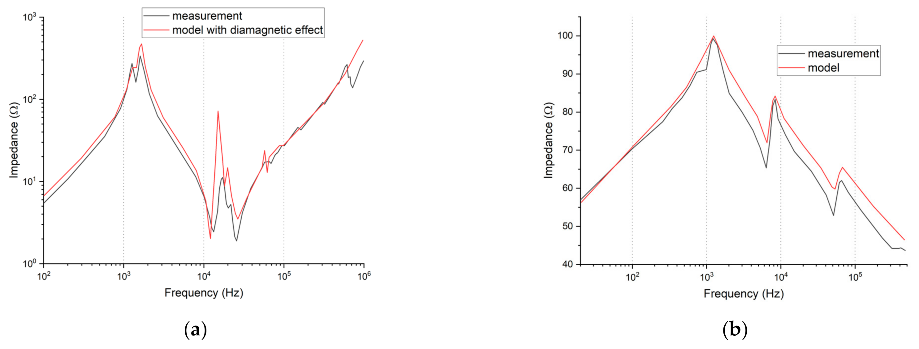
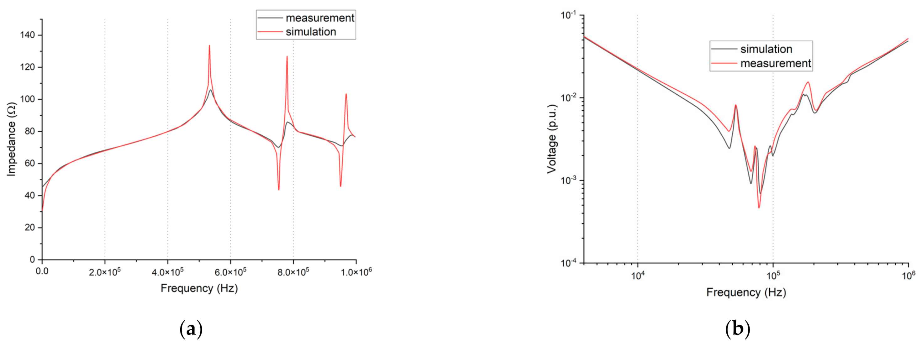
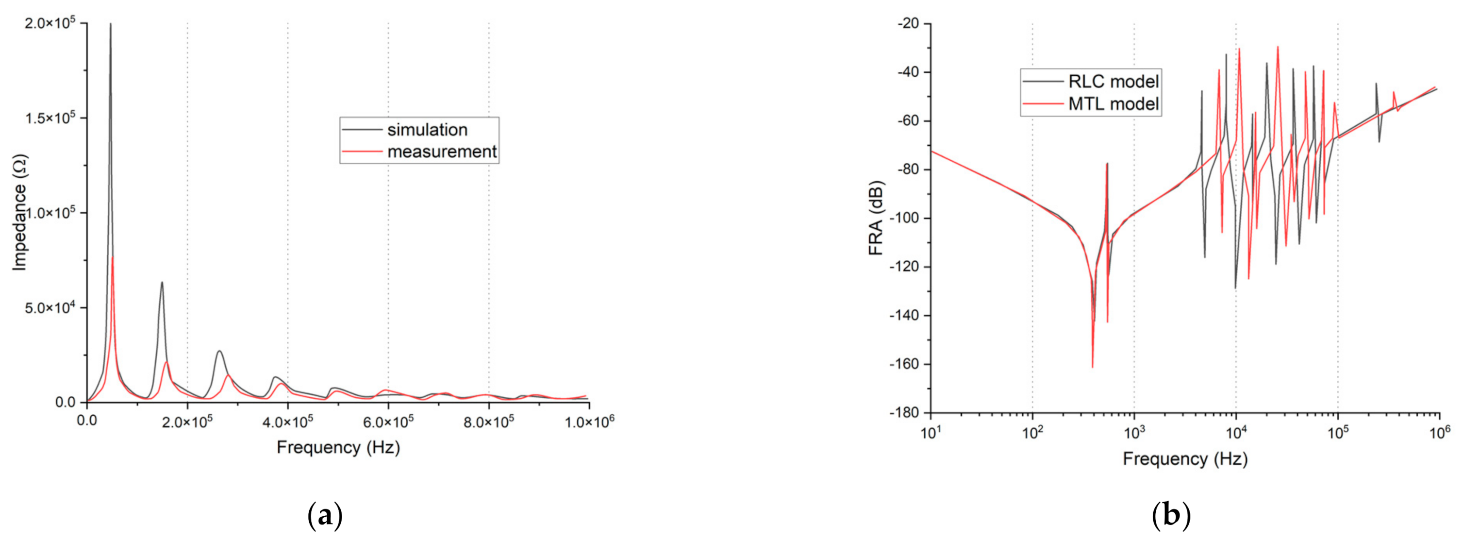
70], the effects of frequency-dependent dielectric losses are considered in transformer frequency response and in addition core losses are added to transformer model as parallel resistances. The model is based on traditional analytical calculation of parameters. The modelled object is a 20 kV/0.4 kV, 1.6 MVA transformer. The comparison of modelled frequency response to the real measurement is presented in
Figure 4a. Another example can be found in [
66], where a 1.3-MVA 11-kV/433-V Dyn1 transformer’s frequency response was obtained using wideband three-phase transformer models based on three types of FRA tests. The results show good conformity, which is shown in
Figure 4b.
Some authors include additional parameters in the simulations, e.g., diamagnetic properties of conductors [
57], and the results of such modelling based on lumped parameters ladder are given in
Figure 5a. Such a lumped parameters network may be modified, as in [
21], where an analytical method for the transfer function calculation was based on a cascade model of parallel RLC cells. The results of RLC modelling and calculated transfer function compared to the measurement given in
Figure 5b.
To summarize the RLC lumped parameters ladders modelling techniques, it can be stated that it is possible to achieve similarity to real objects. The biggest problem in such an approach is the construction of models, which may be built from a large number of parameters (R, L, C, M) and estimation of these parameters’ values. More detailed calculation of these parameters can be based on FEM models, as described in the following section.
4. Lumped Parameter Approach Based on Parameter Extraction from FEM
The concept is based on linking electromagnetic field analysis with network modelling. The windings are divided into elementary parts, which, in this case, are single turns. Many authors assume the whole disc to be elementary. This approach simplifies the resulting finite element mesh, but in the authors’ opinions, such a model is too simplistic and causes many important parameters to be missed, which leads to considerable errors in the FRA diagrams obtained. Dividing the winding into individual turns produces an unconnected set of wires, each of which lies approximately in one plane. This makes the application of 2D finite element models possible. In this way, the numerical calculations are shortened, or made possible in the case of windings with many hundreds of turns. It should be emphasized at this point that the whole structure of the transformer does not have cylindrical symmetry, so the use of a 2D model causes some approximations. Methods for obtaining a 3D close-to-real core reluctance in a 2D model are presented below.
For calculations of the RLC parameters of the abovementioned single turns, the commercial ANSYS Maxwell package was applied. This program is able to calculate the impedance matrices necessary in network models. Dependent on the chosen option, either inductances with resistances or capacitances can be determined. Electrostatic field analysis provides the self- and mutual capacitances:
where: Φ is the scalar potential of the electric field inducted with charge having a density of
ρ and
ε0 and
εr are vacuum permittivity and relative environment permittivity.
The self- and mutual capacitances were found by feeding turns
i,
j with voltage and calculating the electric field energy
Wij:
D and
E are vectors of the electric induction and electric field intensity.
The calculation of the self- and mutual inductances is performed with a 2D electromagnetic field equation, which took into account the effect of the eddy currents in the wires:
where:
A is the magnetic vector potential,
ω is the current pulsation, and
μ and
γ the magnetic permeability and conductivity of environment.
Js is the current density in the windings. The induction matrices were obtained from the magnetic field energy
WAV, which was calculated from two models,
i and
j, with the feeding current having a peak value
IPeak in both turns:
B and
H are vectors of the induction and field intensity of the magnetic field.
The resistance values of the turns were provided by their active power losses
P due to the current flow with density
J:
where:
IPeak is the feeding current peak value and
γ is the wire conductivity.
The analyzed area should be discretized with enough dense elements in order to obtain satisfactory results for frequencies above 1 MHz, especially when calculating the resistance of the wires. However, the skin effect at high frequency is clearly visible not only in the values of the winding resistance but also in the mutual and own inductances.
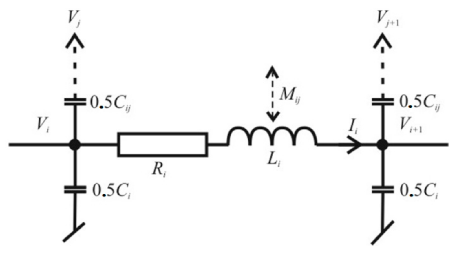
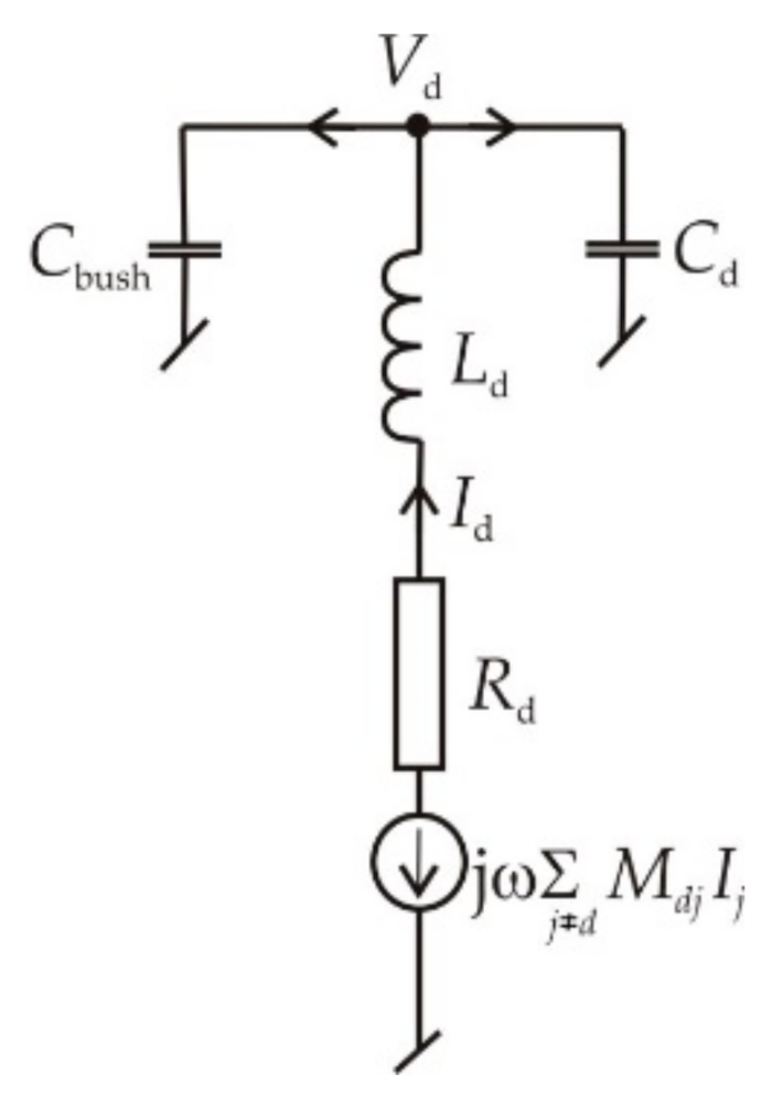
The second part of the proposed algorithm is the network solution. For a single turn, the simple replacement model of an Ⅱ-shape is proposed (
Figure 6). This model takes into consideration the relationships between all the turns in the winding as it contains the mutual inductances
Mij and capacitances
Cij versus all the other turns.
The branches shown in
Figure 6 are then in series to form a whole winding.
Serial connection of the wire’s models is presented in
Figure 7. This form of the algorithm does not consider parallel connections in the winding. The proposed network model takes into account mutual inductances and capacitances between all the wires. To solve the whole network the following equation system is given:
This equation system has 2 × number_of_turns and its matrix is densely populated.
All RLC parameters in the network are taken from 2D analysis of the electromagnetic field described above. Such an approach allows to perform more detailed calculations of the high-frequency field penetration into the conducting wires, when compared to 3D modela, because the number of finite elements in the model can be much higher. FEM application the lumped parameters calculations seems to still be competitive versus the analytical methods proposed in [
71], which do not take into account the skin and proximity effects in the wires. The wires’ inductance is lowered by about 10% at high frequency by th einfluence of these two effects. However, implementation of the 2D finite element transformer model requires additional means to obtain results equivalent to real, 3D models.
The described methodology was tested using the core-less coil of diameter 0.6 m, containing 54 wires. The coil was a part of the winding removed from distribution transformer 0.8 kVA. It is compared to other modeled objects in
Table A1 in
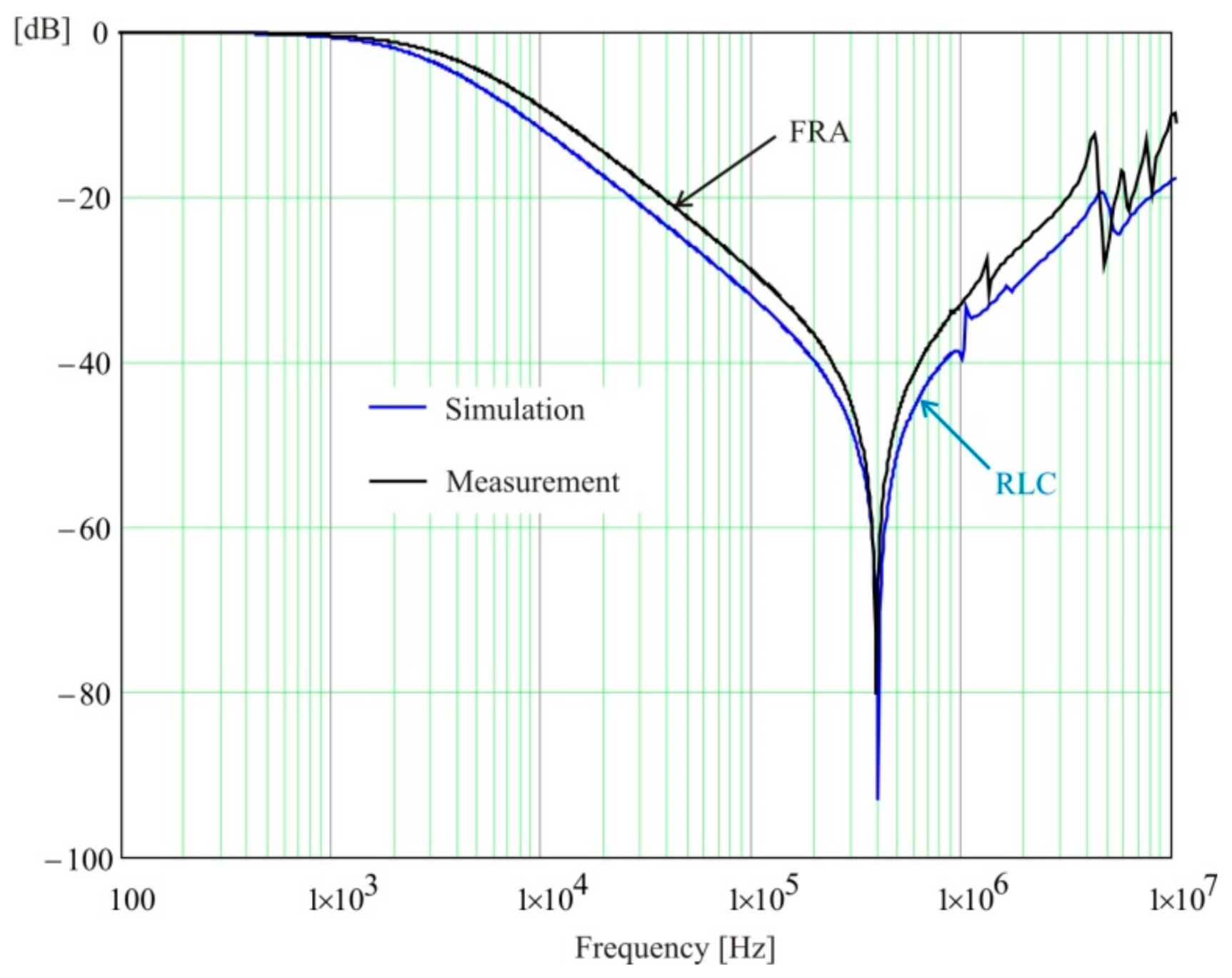
Appendix A. The response obtained from simulation is compared to FRA measurement in
Figure 8. One can observe differences occurring above 4 MHz.
The example of application of FEM calculated parameters for lumped parameters model can be found in [
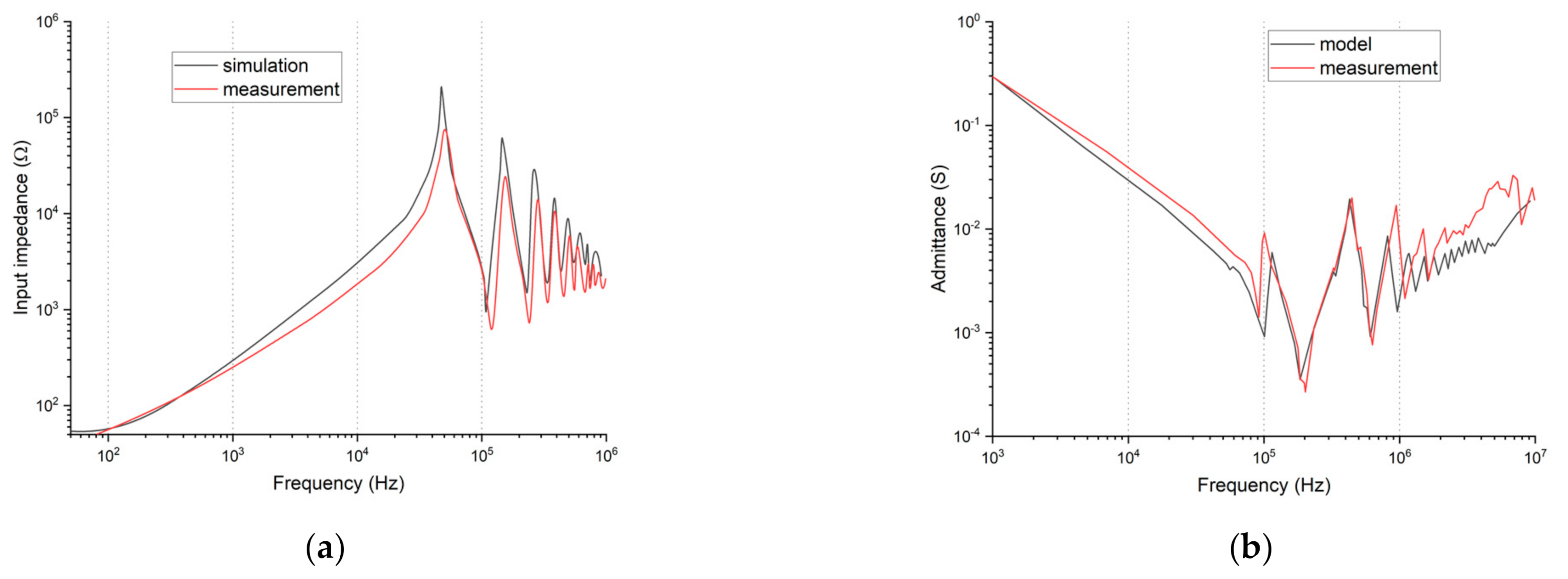
72]. In this paper, a lumped parameters ladder network of an actual transformer winding was constructed. The investigated coil, having dimensions of 50 × 20 cm and no iron core, was discretized into five identical sections. The results were calculated as impedance changes over frequency and are presented on
Figure 9a. The next example shows the construction of the model for a dry-type transformer 20/0.4 kV based on the network of inductances, capacitances and resistances calculated using FEM [
73]. The comparison of the model’s frequency response to the measurement is presented in
Figure 9b.
The details of FEM calculation of capacitances and inductances for application in equivalent circuit models is described in [
74]. The model is also used for the simulation of various deformations in the winding. The effect of this modelling is presented in
Figure 10a. The introduction of frequency-dependent losses into the FEM model, such as eddy current effects (core losses and skin/proximity losses in the winding) and dielectric losses in the insulation is described in [
75], while the effect is plotted in
Figure 10b.
The application of FEM calculation to distributed models allows for more detailed values of modelled parameters. In addition, it is possible to take under consideration additional phenomena in transformer winding—for example, various losses and material parameters (magnetic core, dielectric insulation). This is currently the most popular method for modelling frequency responses of transformer windings.
5. Distributed Parameter Approach—Wave Effects in Windings
The frequency of the excitation current when using FRA reaches over 1 MHz. The wavelength at this frequency is about 300 m and it is comparable to the length of the wires of a primary winding in an HV transformer. Analysing FRA diagrams, we can observe the sweep of the phase shift at this frequency point, where the characteristic of the slope of the amplitude changes from inductive to capacitive. However, this effect may be observed only at relative low frequencies—i.e., under 100 kHz. In the high-frequency area, the phase shift and amplitude characteristic seem to be independent. The phase shift reaches large, inductive values. The explanation for this phenomenon lies in the phase delay caused by wave effects. Simple RLC models cannot take this behavior into account and a new model, based on transmission line segments, has to be proposed. Similar models were described in [
25,
26].
One segment of a transmission line corresponds to a single wire. While evaluating the parameters of these wires using the finite element method, the polar symmetry of the winding is utilized, which makes calculations possible in a two-dimensional model. However, the winding with polar symmetry cannot be further helical, but consists of independent loops, which will be interconnected later.
The model shown in
Figure 11 takes into account all possible inductive couplings between the wires, their resistances, as well as all capacitive couplings. For each loop, the well-known telegraph equation is used, which for the whole winding takes the matrix form of
Z and
Y are the matrices of own and mutual impedances and the admittances per unit length for the whole winding. As long as (7) presents a coupled differential equation system, the analytical solution is difficult or even impossible. One of the possible solutions is the decomposition of
Z and
Y to their diagonal forms:
Matrices
Pu and
Pi may be calculated by the eigendecomposition of
ZY and
YZ:
Matrices
Z and
Y are symmetric. Their product means
Z·
Y = (
Y·
Z)
T. So, if the decomposition of
Y·
Z is known, the decomposition of
Z·
Y may be easily obtained from:
Now, the diagonal matrices,
ZD =
Pu−1·
Z·
Pi and
YD =
Pi−1·
Y·
Pu, can be obtained. At this point, we have a set of uncoupled telegraph equations, which can be solved in the usual manner:
The solution of the telegraph equations gives the modal values
Um and
Im. The chain matrix for one segment of the transmission line takes the form:
with:
.
The complete, helical winding is now built from line segments corresponding to single wires.
where:
Am,xx are diagonal matrices containing appropriate terms taken from the solution for the single segment (6) and
Um0,
Im0 denote values at the beginning of the wires. Substituting the decomposed voltages and currents with the originals
the following equation system for the whole winding is obtained:
which, for the further construction of the numerical algorithm, will be simplified to:
The approach based on distributed parameters is based on the same RLC parameters of the winding as the model using lumped parameters, which are derived from the electromagnetic and electric field analysis described in
Section 4. However, as this approach requires the decomposition of large matrices, it is much more time consuming. The advantage of this algorithm becomes apparent in the high-frequency range, where the modelling results are more accurate.
The presented concept has one drawback. When modelling windings with a significant number of turns, the RLC parameters of the individual turns differ only slightly. As a result, the eigenvalues used in the solution are almost the same and the decomposition algorithm becomes unstable.
This algorithm was tested using the same core-less coil with 54 wires, as described in
Section 4. The geometry is compared to other modeled objects in
Table A1 in
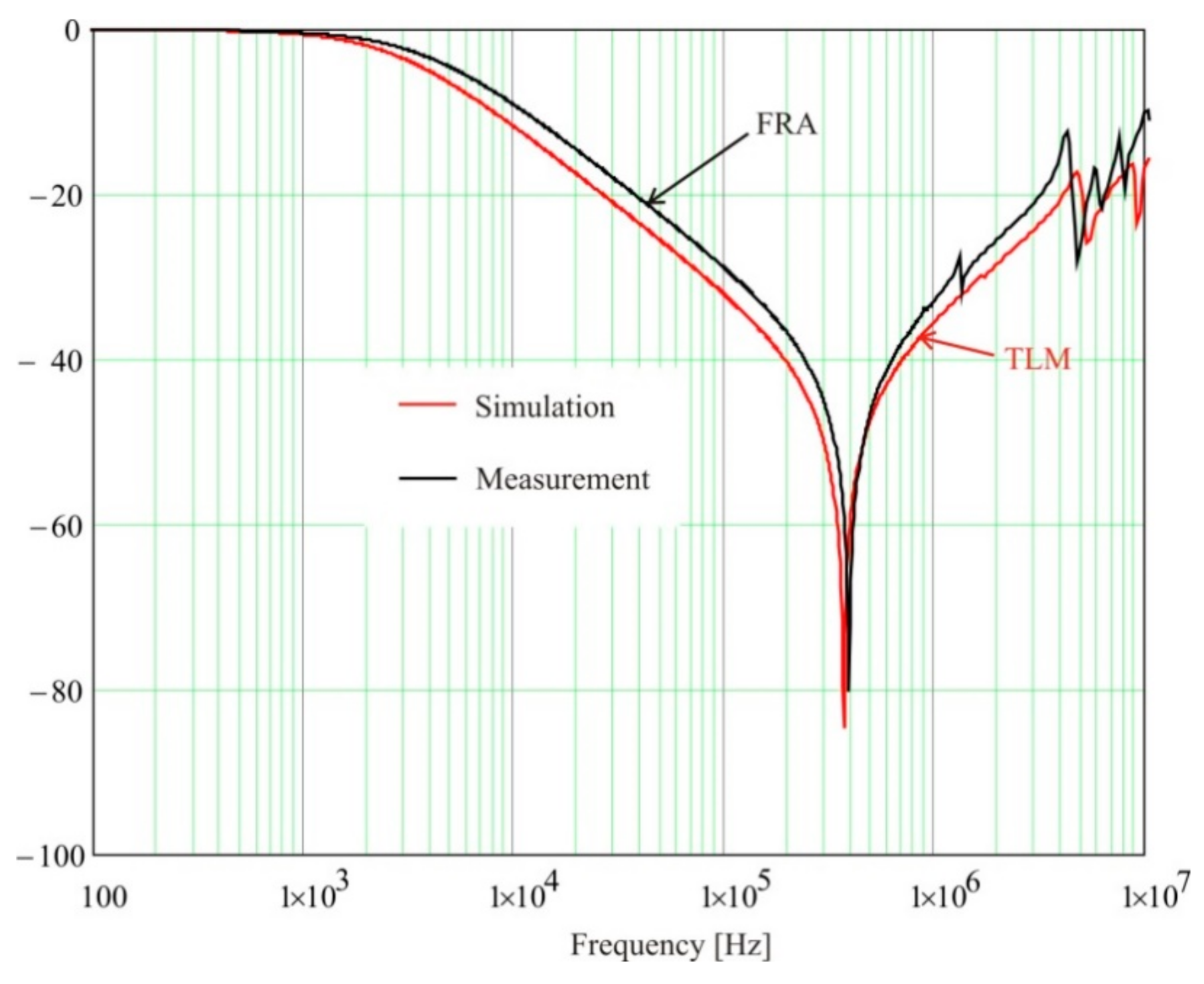
Appendix A. The comparison to the FRA measurement in
Figure 12 shows better agreement in the high-frequency area than the lumped parameter model.
The application of travelling wave phenomena and a multi-conductor transmission line (MTL) in FRA modelling is described in [
24]. The simulation and measurement were conducted for a simple coil without a core, having 30 double discs HV winding and a 23 turn helical LV winding. Their comparison is shown in
Figure 13a. The authors of [
76] discuss modelling results from two methods: lumped parameters and MTL approach for the simulation of HV and LV windings of a 10 kVA transformer. The results of the simulation are shown in
Figure 13b, where ER describes the lumped parameters model and NR describes the MTL model. It can be seen that both methods can be used for frequency response modelling; however, they show some differences in the location of resonances along the frequency domain.
7. Model of Windings Connected in Parallel
Windings connected in parallel can be often found in power transformer constructions, due to high values of currents. In [
78], the authors present an algorithm in which the presence of parallel wires in a winding is taken into consideration. Parallel wires in windings are popular in low voltage windings. The computer models usually use here a simplification by neglecting the parallel connections. However, such an approach might lead to errors in the frequency response results. Parallel coils have locally different lengths, which is equalized in the whole winding by interlacing these coils. Nevertheless, different magnetic couplings may appear at local spots, which influence the shape of a frequency response. In addition, capacitive coupling exists between parallel wires. Additional complications are related to the skin and proximity effects of the parallel wires. Similarly to the models described above, a computer modelled solution in real 3D geometry with the computers available today is not possible, because individual wires of the coil have to be modelled. Therefore a 2D model was chosen, with an explanation of the dependencies between 3D and 2D models, which should give comparable results.
The elementary branches used in networks are very similar to those described in
Section 4. However, the branch of the Ⅱ-shape is replaced by a Γ-shape, as is shown in
Figure 16. The reason for this change is to avoid capacitive couplings throughout the winding that lead to incorrect results in the FRA diagrams.
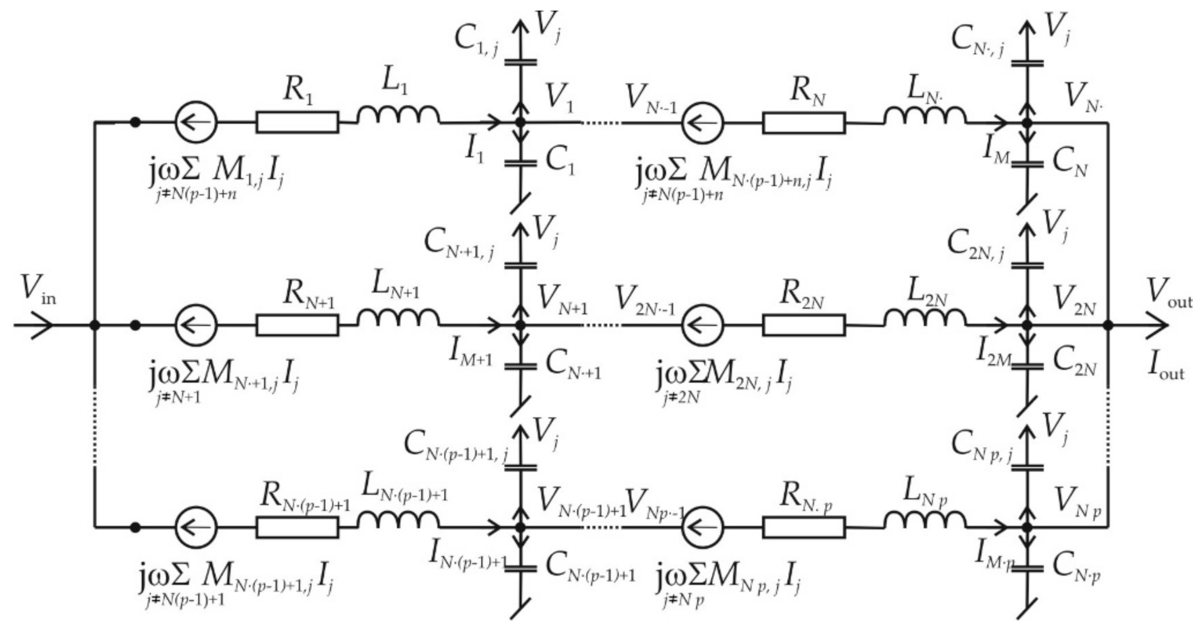
In
Figure 16 and
Figure 17, the variable
N is the number of serial turns in one parallel coil:
n is the actual turn number in the coil and
l is the number of subsequent parallel coils. The subscript
j should be understood to be any other turn in the winding.
Figure 16 presents the model of a single turn consisting of self-inductances
LN(l–1)+n, capacitances to the ground
CN(l–1)+n, resistances
RN(l–1)+n, mutual inductances
MN(l–1)+n, j and capacitances between turns
CN(l–1)+n, j. The assumed model of a Γ-shape includes the mutual inductances and capacitances between all the turns of the winding.
Figure 17 shows the input and output branches of
P parallel connected coils. In this case, the total number of turns is equal to
Ntot =
N·
P. The number of the analyzed turn is
N (
p − 1) +
n, with
p = 1…
P,
n = 1…
N. A value of
n = 1 means the input of the winding, while
n =
N is the winding’s output. The turns are numbered in such a manner that
n = 1…
N changes first, and then
p = 1…
P.
The additional branch for modelling other windings, described in
Section 6, is also included in this network model.
The set of equations describing this model consists of voltage equations and current equations, with respect to Kirchhoff’s law. First come the following voltage equations:
for
n = 1, and next the (
N − 1)
L equations for the remaining turns:
Preparing the current equations starts with the equation for the output branches:
where
Vout is the output voltage, and
RFRA is the input resistance of an FR meter.
For the remaining branches, the following (
N − 1)
L current equations are written:
Implementation of the additional wire representing the other windings requires supplementary terms, which can be seen in Equations (17) and (18), as well as the supplementary voltage and current equations shown below:
The above formulas ensure that the number of unknown voltages and current is equal to the number of equations. The model described can also serve for windings which do not contain parallel connections. In this case, P = 1.
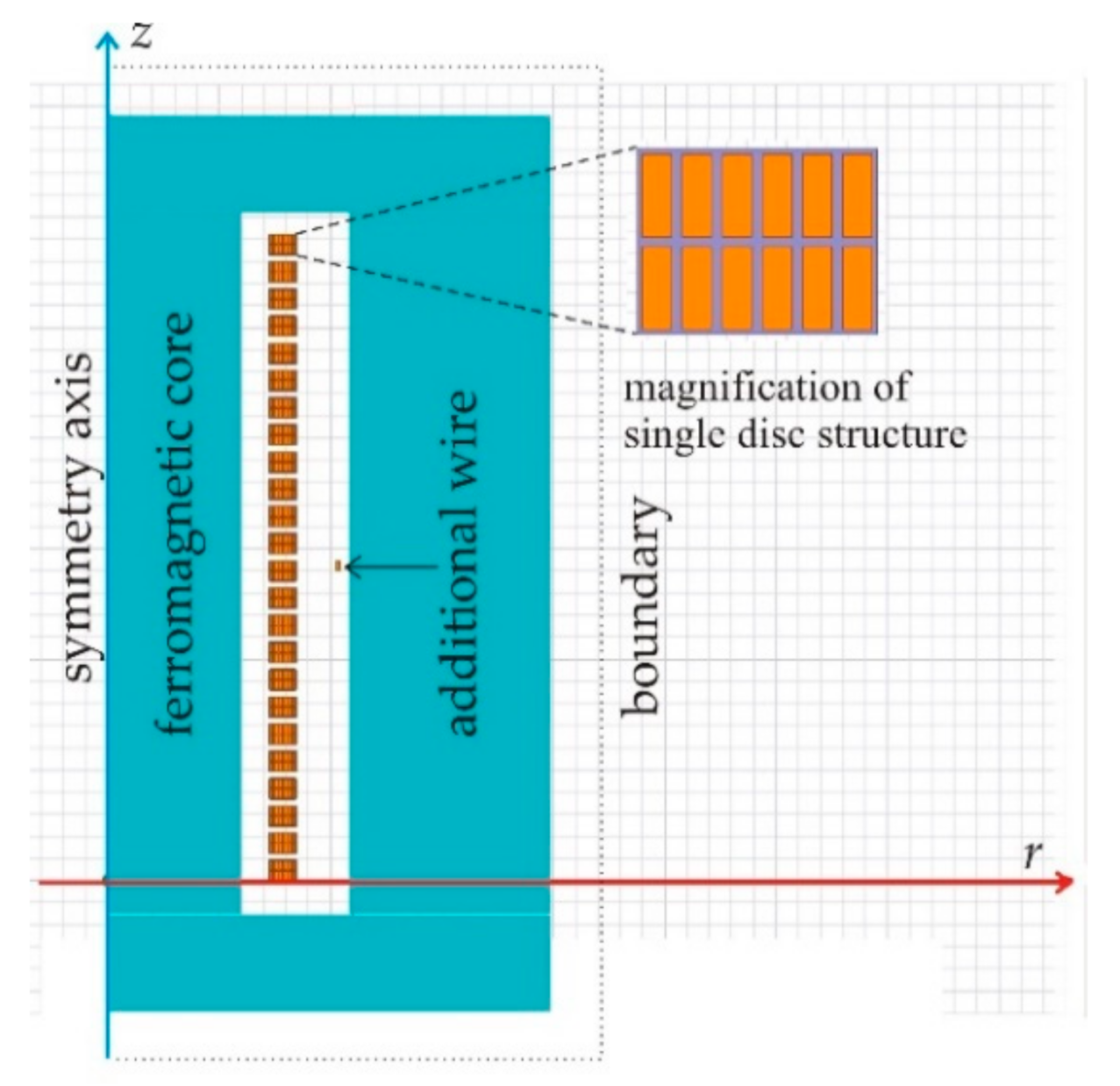
The test simulations were conducted for an 800 kVA, 15/0.4 kV distribution transformer. The LV windings of this transformer contain 24 turns connected in 12 parallel branches. The HV winding of the transformer was opened and disconnected from the bushings. The contours of the finite element model of this transformer used for the calculations of the RLC parameters are shown in
Figure 18. The geometry is compared to other modeled objects in
Table A1 in
Appendix A.
Modelling of the electromagnetic field inside a laminated core has been the subject of many studies. Single lamination modelling by the finite element method should be rejected as ineffective. Therefore, models are needed in which a solid core replaces the laminated one. There are two parameters whose values have to be determined—electric conductivity
γ and magnetic permeability
μ. In most cases, the one-dimensional penetration of an electromagnetic field into ferromagnetic core is considered. Assuming invariability of the power losses in core, the authors of [
79] derive a very simple formula for equivalent conductivity
γe:
where
n means the number of laminations in the core. The authors of [
77] assumed that the electromagnetic energy inside the laminated core and in the solid block are the same. This leads to the same result, as shown in Formula (22). Therefore, the equivalent laminated steel conductivity of the described model is
γ = 1.2 S/m.
One-dimensional theory of field penetration allows determining the equivalent magnetic permeability as frequency-dependent, what was described in [
6,
77].
The 2D and 3D models are based on different coordinate systems, which ultimately leads to differences in the geometry of the modeled objects. The geometry of physical model is three-dimensional, while the 2D model contains much more ferromagnetic material due to the cylindrical symmetry. Different amounts of the ferromagnetic material in 2D and 3D models cause changes in the value of the reluctance in their magnetic circuits and, as a consequence, in the the magnetic flux value. Therefore the initial value of relative permeability was corrected to 510 to obtain the core reluctance of a 2D model equal to that of the real 3D object.
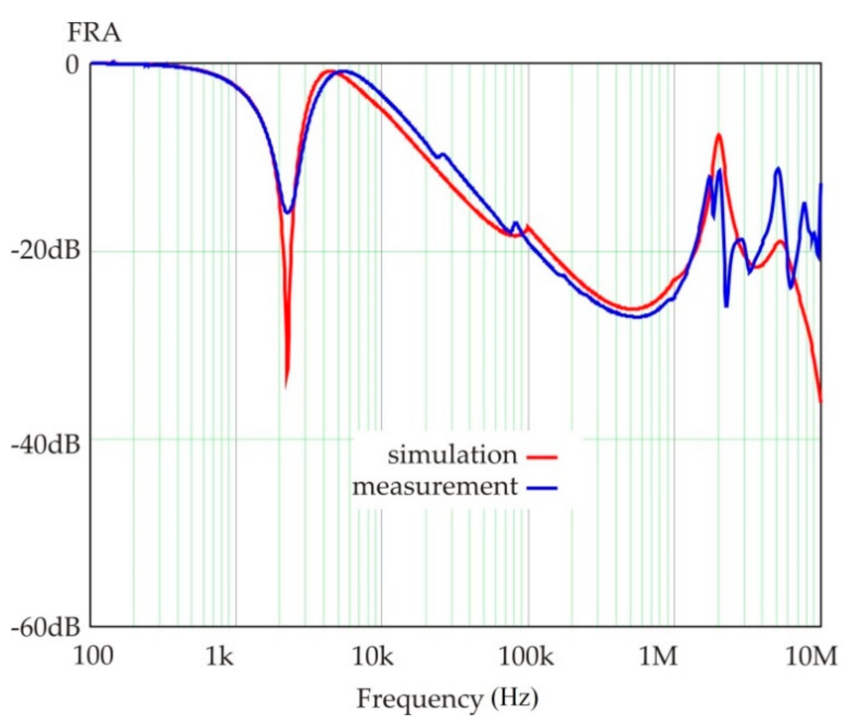
The simulated diagram coincides with the FRA measurement until 2 MHz, as shown in
Figure 19. To improve the conformity for a higher frequency, a denser finite element mesh should be employed. This would be not practical as the calculation of the parameter matrices for this case needs about one week of computer time. The results shown are satisfactory as the measurement of the frequency response usually takes place below 2 MHz.

