1. Introduction
As the energy crisis and environmental problem becomes increasingly severe, the renewable energy represented by wind power has been rapidly developed [
1,
2]. The application of ultra high voltage direct current (UHVDC) is an effective way to transmit wind power over long distances [
3,
4]. UHVDC technology can implement the asynchronous operation between the wind farm in the sending ac grid and the receiving power grid. Furthermore, the DC transmission line does not need reactive power compensation during operation, which can achieve the fast power regulation and flexible power control [
5]. Therefore, UHVDC transmission has received a lot of research and application in long-distance transmission of the renewable energy.
Commutation failure is a common fault for the UHVDC transmission system. The commutation failure in the UHVDC transmission system will bring the new challenge of the fault ride through for the wind power generation system (WPGS) connected to the sending ac grid. When the commutation failure occurs, the rectification angle of the rectifier station will increase due to the sudden decrease of the DC voltage. The reactive power will be greatly absorbed from the sending ac grid, so that the voltage of the sending ac grid will decrease, which will cause the fault situation of low voltage ride through (LVRT) for WPGS. As the commutation failure is cleared, the DC bus voltage gradually rises. At this time, the rectification angle of the rectifier station begins to decrease; thus, the reactive power absorbed by the rectifier station from the sending ac grid will be rapidly reduced. However, the reactive compensation device on the sending ac grid is still operated to supply the excessive reactive power to the sending ac grid, which will cause the high voltage ride through (HVRT) for WPGS during the commutation failure recovery process [
6,
7]. For a sending ac grid with high wind power penetration rate, the peak value of overvoltage caused by the commutation failure can reach more than 1.3 pu, which seriously threatens the normal operation of WPGS and has to be suppressed [
8].
Since the stator of the doubly-fed induction generator (DFIG) is directly connected to the grid, there will be significant impact on the power and current of DFIG system caused by the transient flux linkage characteristic when the grid fault occurs [
9,
10]. The crowbar circuit on the rotor side is usually applied to prevent the overcurrent and overvoltage on the rotor winding; the LVRT/HVRT capability of the DFIG system can be improved [
11,
12]. When the commutation failure occurs in the UHVDC system, the crowbar circuit in DFIG connected to the sending ac grid may be triggered due to the LVRT/HVRT. To calculate the transient characteristics of DFIG system connected to the sending ac grid of the UHVDC system under commutation failure, it is necessary to build a mathematical model for the DFIG system considering the crowbar circuit. Based on the mathematical model, proper crowbar parameters can be selected to enhance the transient reactive power characteristics of the DFIG, which can suppress the overvoltage of the sending ac grid [
13].
In order to calculate the transient reactive power of DFIG system under grid fault, [
14] investigated the relationship between the crowbar resistance and the decay time constant, the rotor voltage, and the rotor current. The authors of [
15] developed the model of the DFIG system with rotor-side crowbar under symmetrical grid faults. In [
16], the authors analyzed the influence of interval between voltage dip and crowbar triggering on transient current characteristics of DFIG system and proposed a DFIG transient mathematical model considering the trigger delay. The authors of [
17] calculated the stator flux linkage of the DFIG in the time domain and proposed that the installation of superconducting magnetic energy storage unit can improve the transient capability of DFIG. The mathematical models proposed in [
14,
15,
16,
17] analyze the grid voltage after the fault as a constant, so they are only suitable for faults under a step change in grid voltage and cannot be applied to the analysis under commutation failures. Aiming at the DFIG on the sending ac grid under commutation failure, [
18] proposed a strategy to suppress the rotor overcurrent after linearly approximating the voltage of the sending ac grid. The mathematical models proposed in [
17] and [
18] only consider the influence of the grid voltage change on the stator flux linkage of DFIG. Commutation failure is a fault with a duration of more than 100 milliseconds, and the time interval between when the failure occurs and the crowbar activation time reaches tens of milliseconds, so the change of RSC output voltage cannot be ignored before the crowbar is activated [
19].
The main contribution of this paper is to establish a mathematical model for the DFIG system that is suitable for the continuous change of the grid voltage amplitude based on the analysis of the complex frequency domain. Based on the proposed mathematical model, the optimal crowbar parameters are selected to improve the transient reactive power characteristics of the DFIG and suppress the sending ac grid overvoltage. The proposed mathematical model has the following three advantages:
The mathematical model designs the grid voltage as a function of time, which solves the problem that the existing mathematical model is not suitable for non-step voltage grid faults, e.g., commutation failure.
The mathematical model calculates the transient reactive power characteristics of the DFIG after the crowbar is disconnected, which solves the problem of calculating the transient characteristics of the DFIG when the grid voltage keeps changing after the crowbar is disconnected. The quantitative calculation for transient reactive power of the DFIG in the whole process of commutation failure is realized.
The mathematical model takes into account the changes of the RSC control loop in the transient process, so that the output changes of the RSC before and after the crowbar is triggered can be quantitatively calculated, which solves the transient reactive power calculation problem under the constant change of the current command.
This paper establishes the mathematical model of the DFIG system considering the crowbar circuit under grid voltage faults including commutation failure to calculate the transient reactive power characteristics.
Section 2 analyzes the working conditions of DFIG system from fault occurrence to crowbar disconnection and builds the mathematical model.
Section 3 verifies the correctness of the mathematical model by CHIL experiments of the 2MW DFIG system.
Section 4 analyzes the influence of crowbar parameters on the transient reactive power characteristics of DFIG under commutation faults and proposes a parameter selection strategy to suppress the overvoltage of the sending ac grid. The overvoltage suppression strategy is verified by building the ±800 kV UHVDC with sending ac grid simulation model based on Matlab/Simulink.
2. Mathematical Modeling of DFIG System
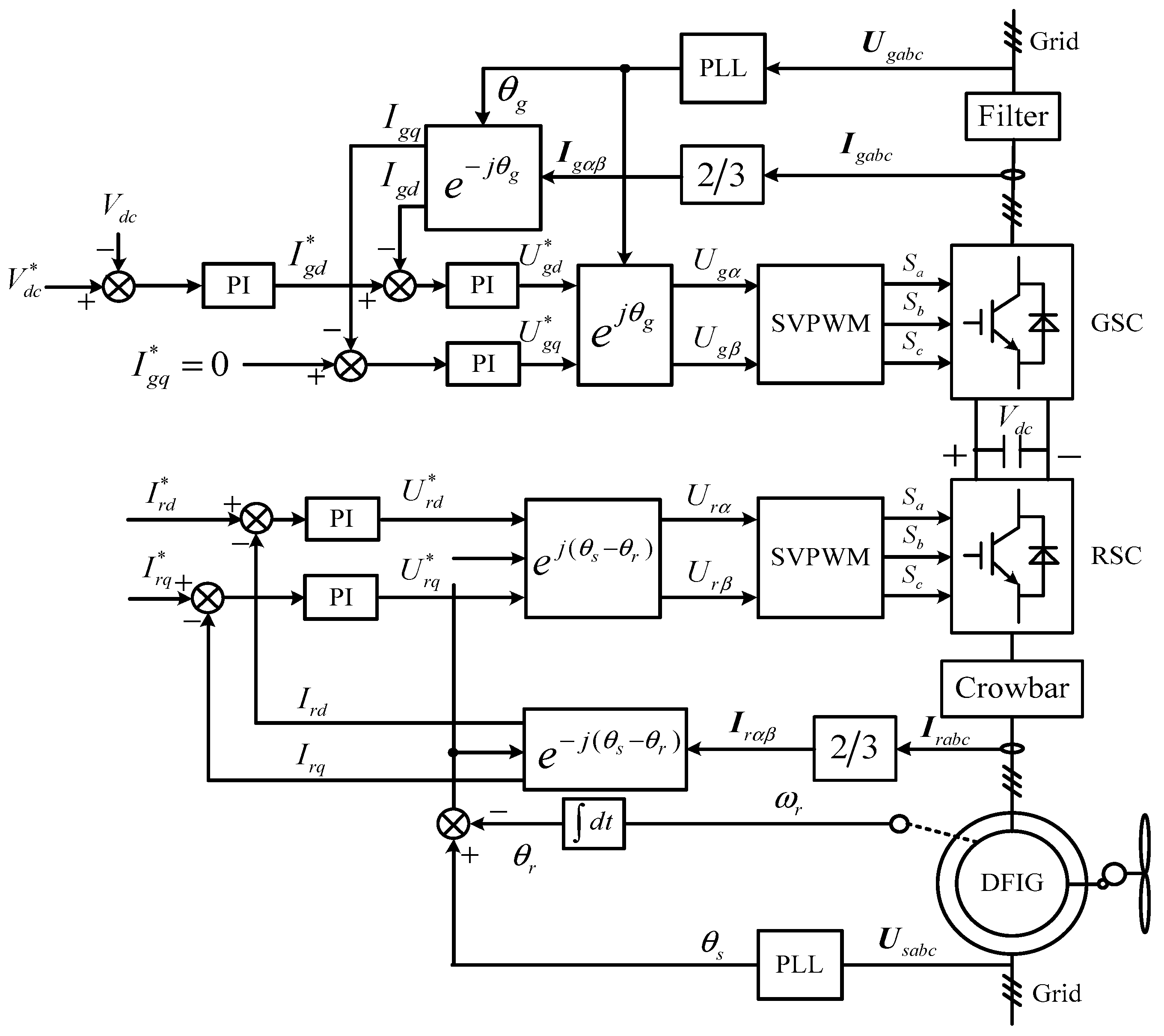
The control block diagram of DFIG is shown in
Figure 1 [
19]. The doubly-fed wind power generation system is connected to the grid through the grid side converter (GSC) and the stator of DFIG. GSC generally employs the unit power factor control strategy. Therefore, analysis of the transient reactive power characteristics of the stator side of DFIG is equivalent to the transient reactive power characteristics of the DFIG system.
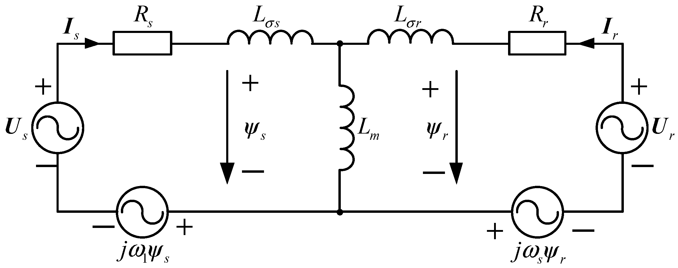
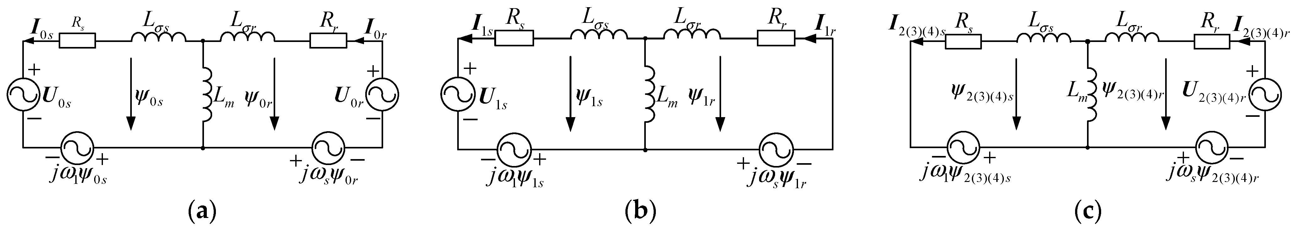
Figure 2 shows the equivalent T circuit diagram of DFIG. Ignoring changes in inductance and resistance of DFIG during the transient process, the stator and rotor flux linkages of DFIG are linear, and the stator and rotor currents of DFIG are linear. Therefore,
jω1ψs and
jωsψr in DFIG are linear units. DFIG is a linear system, and the principle of power superposition can be applied. The specific description of the principle of power superposition is as follows. For a linear system, the response (voltage or current) of any branch in a linear circuit with multiple independent sources is equal to the superposition of the response when each independent source acts alone, and all other independent sources are replaced with their respective impedances [
20].
The topology diagram and control block diagram of crowbar circuit [
18] are shown in
Figure 3. When the rotor current value exceeds the protection value
irmax of RSC, the crowbar is triggered to connect the rotor winding, and then is disconnected from the rotor winding after a period of time. The interval between fault occurring and crowbar triggering is defined as
td1. The duration of connecting the crowbar to the rotor winding is defined as
td2.
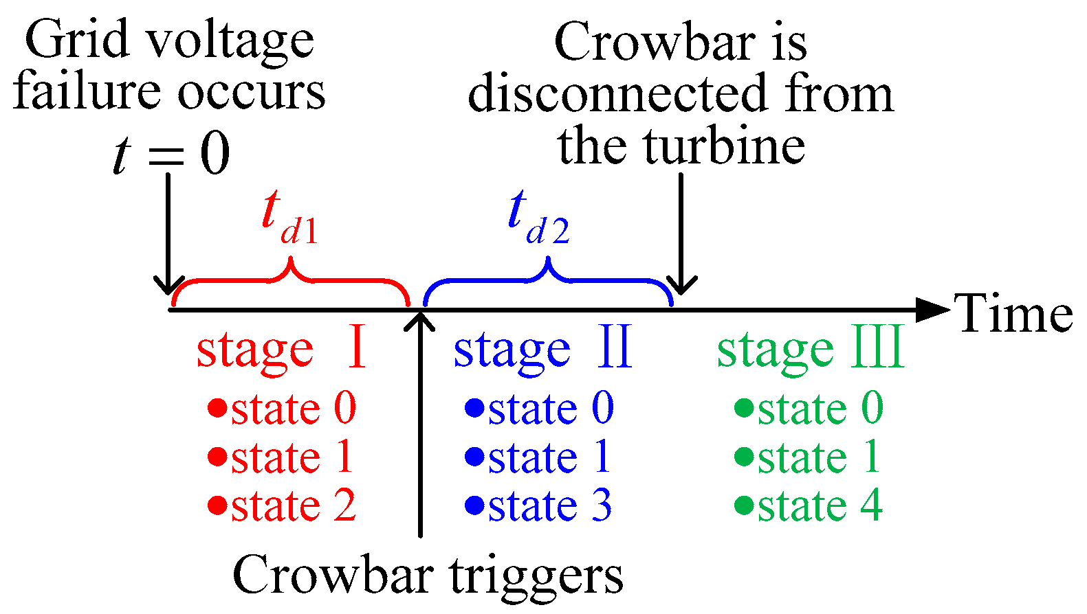
Figure 4 shows the time diagram of crowbar response under grid voltage fault. When grid fault occurs, the transient response of DFIG will go through three stages in sequence, i.e., the stage before the crowbar is triggered (stage I), the stage in which the crowbar is triggered (stage II), and the stage in which the crowbar is disconnected (stage III).
The mathematical model of DFIG system can be divided into three state components according to the superposition theorem of linear circuit, i.e., the steady state before grid fault occurs (State 0), the state in which only the change of grid voltage is considered (State 1), and the state in which only the change of rotor side voltage is considered (State 2 in stage I, State 3 in stage II, and State 4 in stage III). The superimposed state selected under different stages is shown in
Figure 4.
In the following analysis, the subscripts 0, 1, 2, 3, and 4 represent the voltage and current components in State 0, 1, 2, 3, and 4, respectively.
The equivalent circuit diagram in different states is shown in
Figure 5.
Us and
Ur are the amplitude of the phase voltage of stator and rotor winding, Is and Ir are the amplitude of the phase current of stator and rotor winding,
Lm is mutual inductance,
Lσs and
Lσr is leakage inductance of stator winding and rotor winding,
ω1 is the electrical angular speed of the grid voltage,
ωr is the rotor electrical angular speed, and
ωs =
ω1−
ωr.
2.1. State 0
The DFIG system uses the grid power voltage-oriented vector control as shown in
Figure 2; the q-axis component U
0sq of stator voltage is 0. The voltage and current in State 0 can be expressed as:
where
Ibase is the current reference value of the DFIG output before the fault,
Ubase is the voltage reference value of the DFIG before the fault, subscript
q and
d of the current and voltage components represent the
q-axis and
d-axis component,
Ls =
Lσs +
Lm, and
Lr =
Lσr +
Lm.
2.2. State 1
State 1 represents the state where DFIG does not consider RSC output changes under faults. It can decouple the input current and output voltage separately in the RSC control loop by calculating the grid voltage change and RSC output change.
According to
Figure 5b, in order to avoid the complexity of calculation in the time-domain, the current model in State 1 can be expressed in complex frequency domain as:
where
u1sd(
s) is the expression of stator side voltage in complex frequency domain,
Z0 is the impedance matrix in the
dq two-phase synchronous rotating coordinate system of DFIG, which can be expressed as:
2.3. State 2
State 2 is the state in which DFIG considers the RSC output change during the time from the grid fault occurs to the crowbar is triggered. The RSC output will be turned off after the crowbar is triggered. Because the boundary conditions when the crowbar is triggered need to be calculated, the voltage and current in State 2 need to be calculated.
According to
Figure 5c, the current model in State 2 can be expressed in complex frequency domain as:
where
u2rd(
s) is the rotor side voltage on
d-axis and
u2rq(
s) is the rotor side voltage on
q-axis.
According to
Figure 2,
u2rd and
u2rq are calculated by the PI regulator according to the rotor current value, which can be expressed as:
where
krdi and
krdp are the integral coefficient and proportional coefficient of the
d-axis current loop in the RSC,
krqi and
krqp are the integral coefficient and proportional coefficient of the
q-axis current loop in the RSC, and Δ
i2rd(
t) and Δ
i2rq(
t) can be expressed as:
where
(
t) and
(
t) are calculated by maximum power point tracking (MPPT) scheme of the wind power system [
20].
Substituting (6) into (5), (5) can be expressed in complex frequency domain as:
where
Krd =
krdp +
krdi/
s,
Krq =
krqp +
krqi/
s,
Z2 adds the current loop control parameters based on
Z0, which can be expressed as:
Same as in State 1, i2sd(t), i2sq(t), i2rd(t), and i2rq(t) can be obtained by invers-Laplace transforming i2sd(s), i2sq(s), i2rd(s), and i2rq(s).
The transient current in stage I can be expressed as:
The three-phase phase current of the actual rotor winding can be expressed as:
where
Ke is the stator to rotor voltage conversion ratio,
φ0 is the phase angle of the rotor current when the fault occurs, the calculation results of the current take the real part.
When the rotor current exceeds the protection value of RSC, the crowbar is triggered.
2.4. State 3
State 3 is the state in which DFIG considers the voltage during the triggering period of the crowbar. Similarly, in order to calculate the boundary condition when the crowbar is disconnected, the voltage and current in State 3 need to be calculated.
When the crowbar is triggered (
t = 0 in State 3), the initial transient currents can be expressed as:
Similarly, the current model of State 3 in complex frequency domain can be expressed as:
Considering the initial value of the current when the crowbar is triggered,
i3sd,
i3sq,
i3rd, and
i3rq are divided into two parts in the time-domain, which can be expressed as:
where
i’ represents the dynamic component of current.
According to
Figure 3,
U3r is the voltage on the crowbar resistor,
u3rd(
t) and
u3rd(
t) can be expressed as:
where
Rcb is the equivalent resistance of the crowbar resistor to the stator side of DFIG.
The conversion relationship between the value of
Rcb and the actual crowbar resistor value needs to be calculated [
21]. The equivalent resistance
Rcb can be expressed as:
where
Id is the DC current passing through the crowbar resistor,
Ud is the DC voltage on the crowbar resistor, and
Rcrowbar is the actual crowbar resistor value.
Substituting (15) into (13), (13) can be expressed in complex frequency domain as:
Z3 adds the crowbar resistor to the rotor side resistor based on Z0, which can be expressed as:
Since there is a time difference between the initial moment in State 3 and the initial moment in State 1,
i1sd3(
s),
i1sq3(
s),
i1rd3(
s) and
i1rq3(
s) can be expressed as:
where
u1rd3(
s) is the representation of
u1rd(
t+
td1) in complex frequency domain. Invers–Laplace transformation of
i3sd(
s),
i3sq(
s),
i3rd(
s), and
i3rq(
s) can obtain the time–domain model of
i3sd(
t),
i3sq(
t),
i3rd(
t), and
i3rq(
t). Similarly,
i1sd3(
t),
i1sq3(
t),
i1rd3(
t), and
i1rq3(
t) can be obtained.
The transient current of DFIG in stage II can be expressed as:
2.5. State 4
State 4 is the state in which DFIG considers the RSC output change after the crowbar is disconnected. The main difference between State 4 and State 2 is the initial value of rotor current, stator current, and the current loop integrator in RSC.
When the crowbar is disconnected from the rotor winding (
t = 0 in State 4), the initial transient currents can be expressed as:
By changing all of the subscripts 3 in (13) and (14) to 4, the current model in State 4 can be obtained.
Similar to State 2,
u4rd(
t) and
u4rd(
t) can be calculated by PI regulator. However, the initial value of the integrator in State 4 is zero when the crowbar is triggered.
u4rd(
t) and
u4rd(
t) can be expressed as:
The stator current can be expressed as:
Similarly, there is a time difference between the initial moment in State 4 and the initial moment in State 1;
i1sd4(
s),
i1sq4(
s),
i1rd4(
s), and
i1rq4(
s) can be expressed as:
Similar to State 3,
i4sd(
t),
i4sq(
t),
i4rd(
t),
i4rq(
t),
i1sd4(
t),
i1sq4(
t),
i1rd4(
t), and
i1rq4(
t) can be obtained. The transient current of DFIG in stage III can be expressed as:
The transient voltage of DFIG can be expressed as:
The transient reactive power output from the DFIG system to the grid on the grid fault considering the crowbar circuit can be expressed as:
3. Experimental Validation
In order to validate the correctness of the mathematical model in
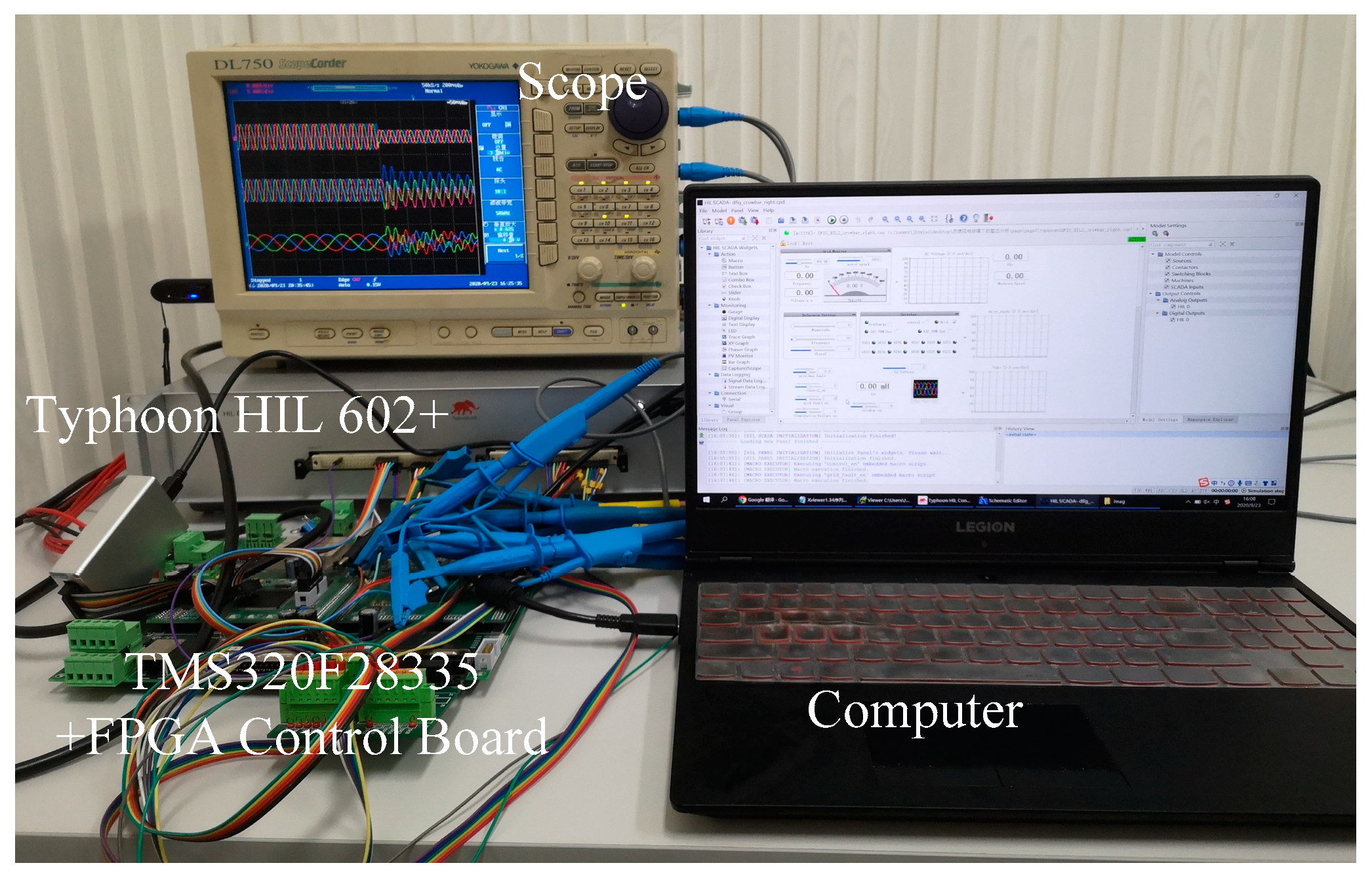
Section 2, a 2MW DFIG system is built based on CHIL platform for experiment as shown in
Figure 6. The detailed parameters of the DFIG system are given in
Appendix A. According to the requirements of IEC61400-21, the wind turbine should not be disconnected from the grid when the grid voltage steps down. The experiment is designed to test two situations where the grid voltage steps down to 0.5 pu and steps down to 0.8 pu. The reactive power command of DFIG meets the IEC standard during the fault.
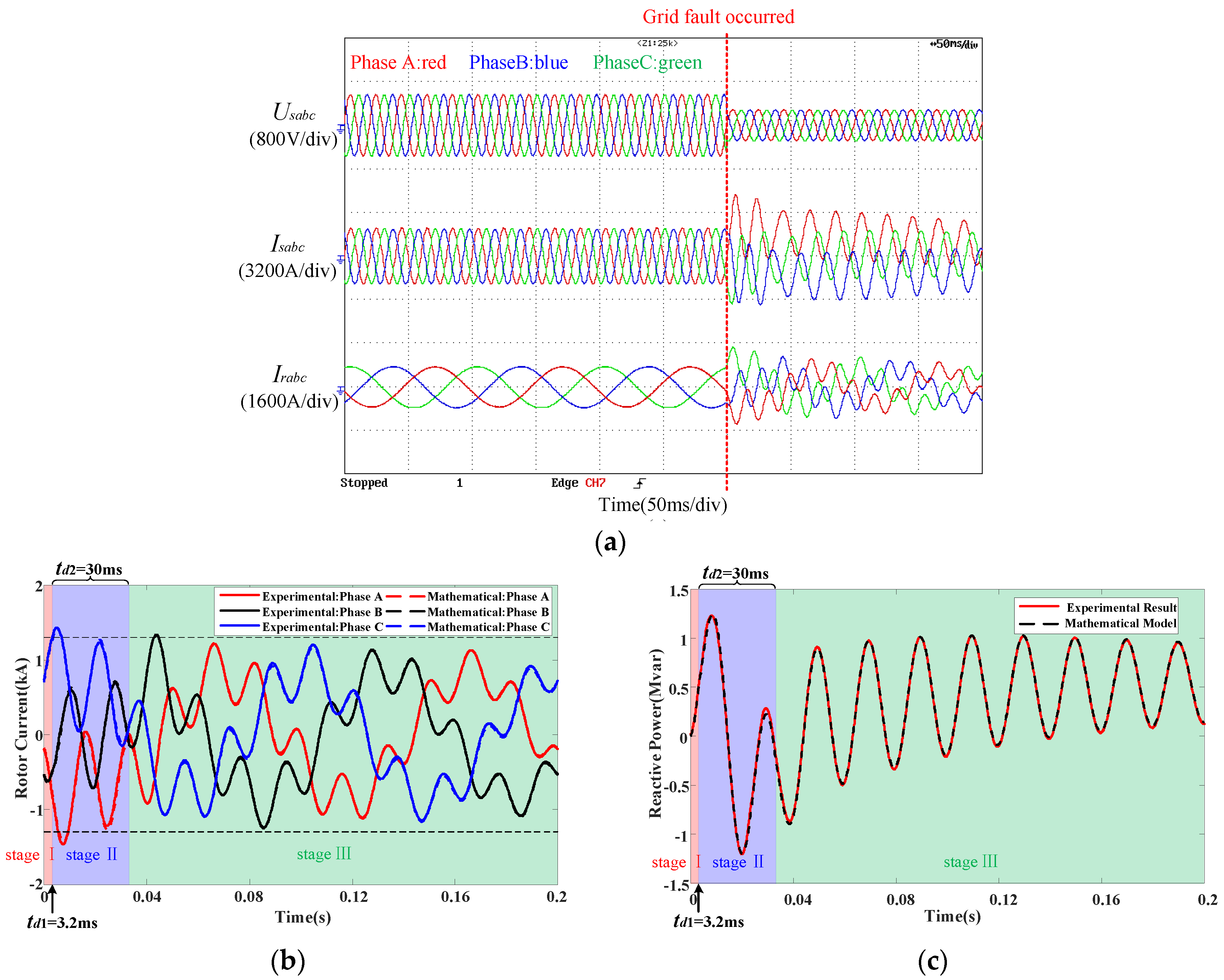
Figure 7 shows the experimental results when grid voltage steps down to 0.5 pu.
Figure 7a shows the experimental waveform of stator voltage
Usabc, the stator current
Isabc, and rotor side current
Irabc sampled by the scope. According to the experimental results, the crowbar of DFIG will be triggered when the grid voltage steps down to 0.5 pu. The stage before the crowbar is triggered (stage I) is indicated by a red background. The stage in which the crowbar is triggered (stage II) is indicated by a blue background. The stage in which the crowbar is disconnected (stage III) is indicated by a green background.
The rotor side current
Irabc of the experimental result is used to compare with the calculation result of the mathematical model in the
Section 2. The comparison of the rotor current when the grid voltage steps down to 0.5 pu is shown in
Figure 7b. The experimental result of the reactive power is calculated by the stator voltage and the stator current. The comparison between the experimental result and calculation result of the transient reactive power when the grid voltage steps down to 0.5 pu is shown in
Figure 7c.
According to
Figure 7b, the rotor current error is less than 2% of the rated rotor current during the entire transient process. According to
Figure 7c, the power error of DFIG is less than 3% of the rated power during the entire transient process. When the grid voltage steps down to 0.5 pu and the crowbar of DFIG is triggered, the proposed mathematical model can accurately calculate the reactive power characteristics of DFIG.
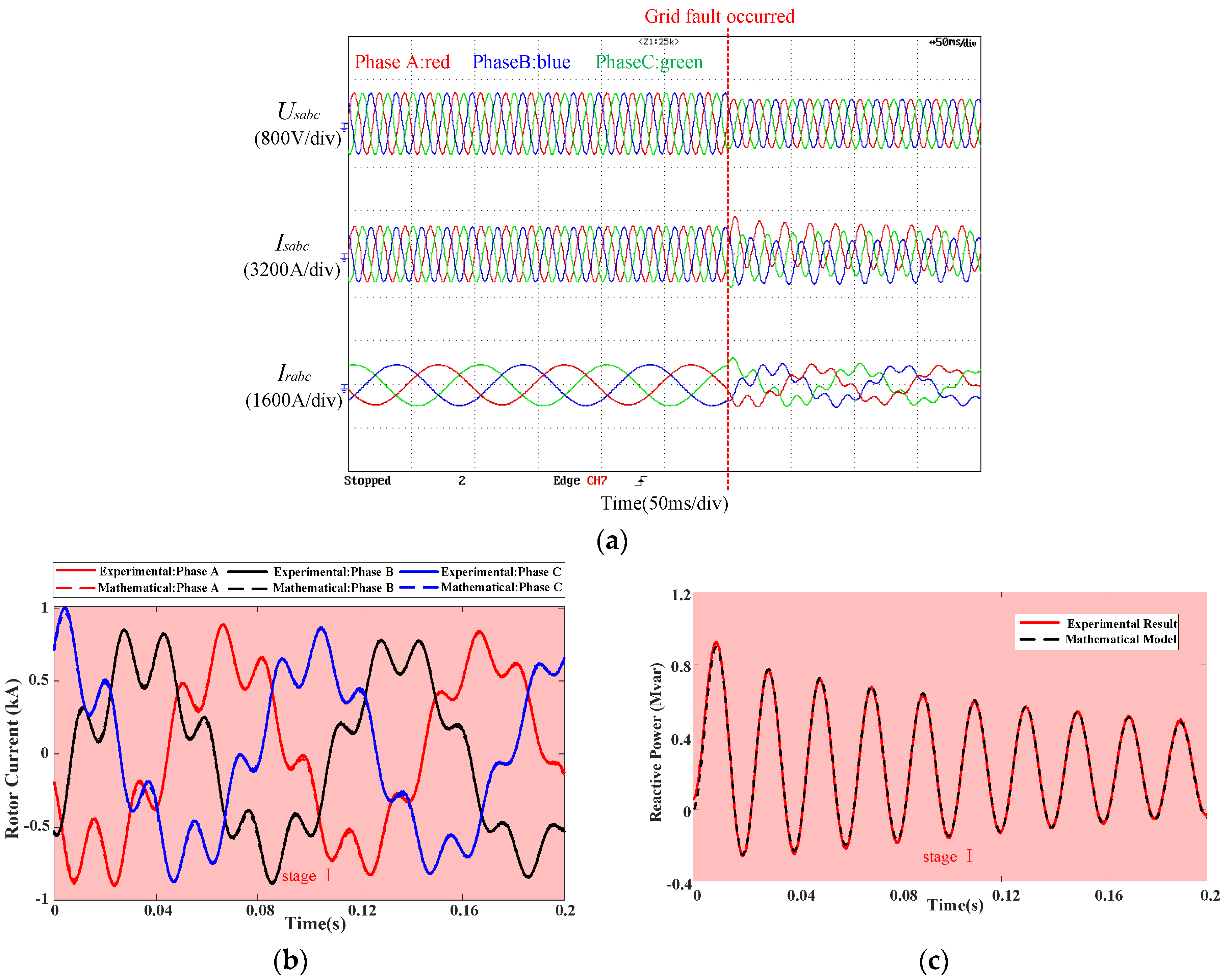
Figure 8 shows the experimental results when grid voltage steps down to 0.8 pu.
Figure 8a shows the experimental waveform of stator voltage, the stator current, and rotor side current. According to the experimental results, the crowbar of DFIG will not be triggered when the grid voltage steps down to 0.8 pu. Since the crowbar is not triggered during the transient process, DFIG is always in stage I with a red background.
The comparison between the experimental result and calculation result of the rotor current when the grid voltage steps down to 0.8 pu is shown in
Figure 8b. The comparison between the experimental result and calculation result of the transient reactive power when the grid voltage steps down to 0.8 pu is shown in
Figure 8c.
According to
Figure 8b, the rotor current error is less than 4% of the rated rotor current during the entire transient process. According to
Figure 8c, the power error of DFIG is less than 4% of the rated power during the entire transient process. When the grid voltage steps down to 0.8 pu and the crowbar of DFIG is not triggered, the proposed mathematical model can accurately calculate the reactive power characteristics of DFIG.
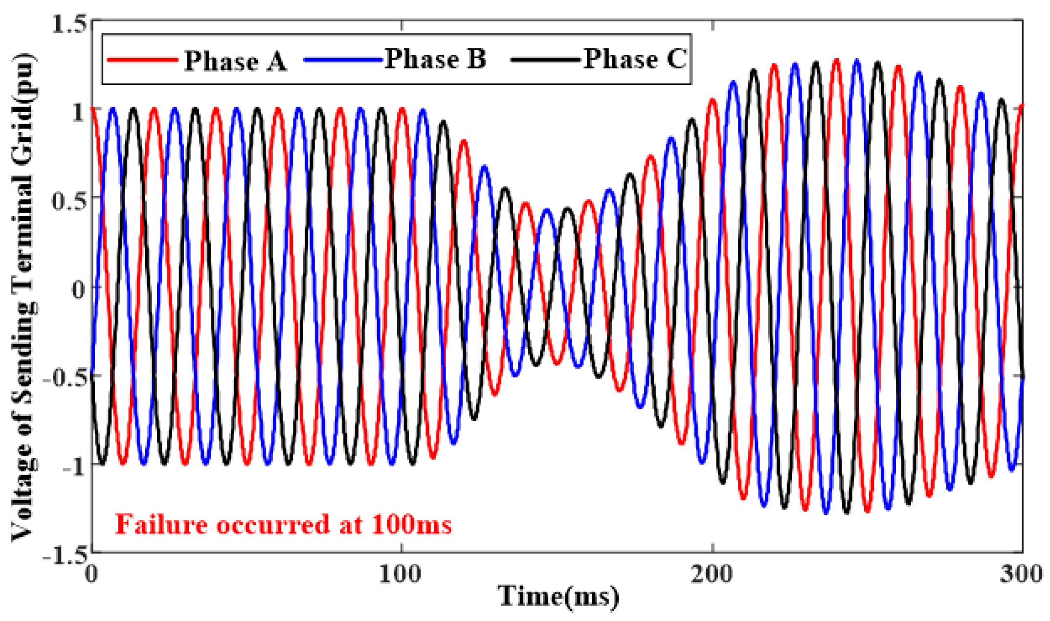
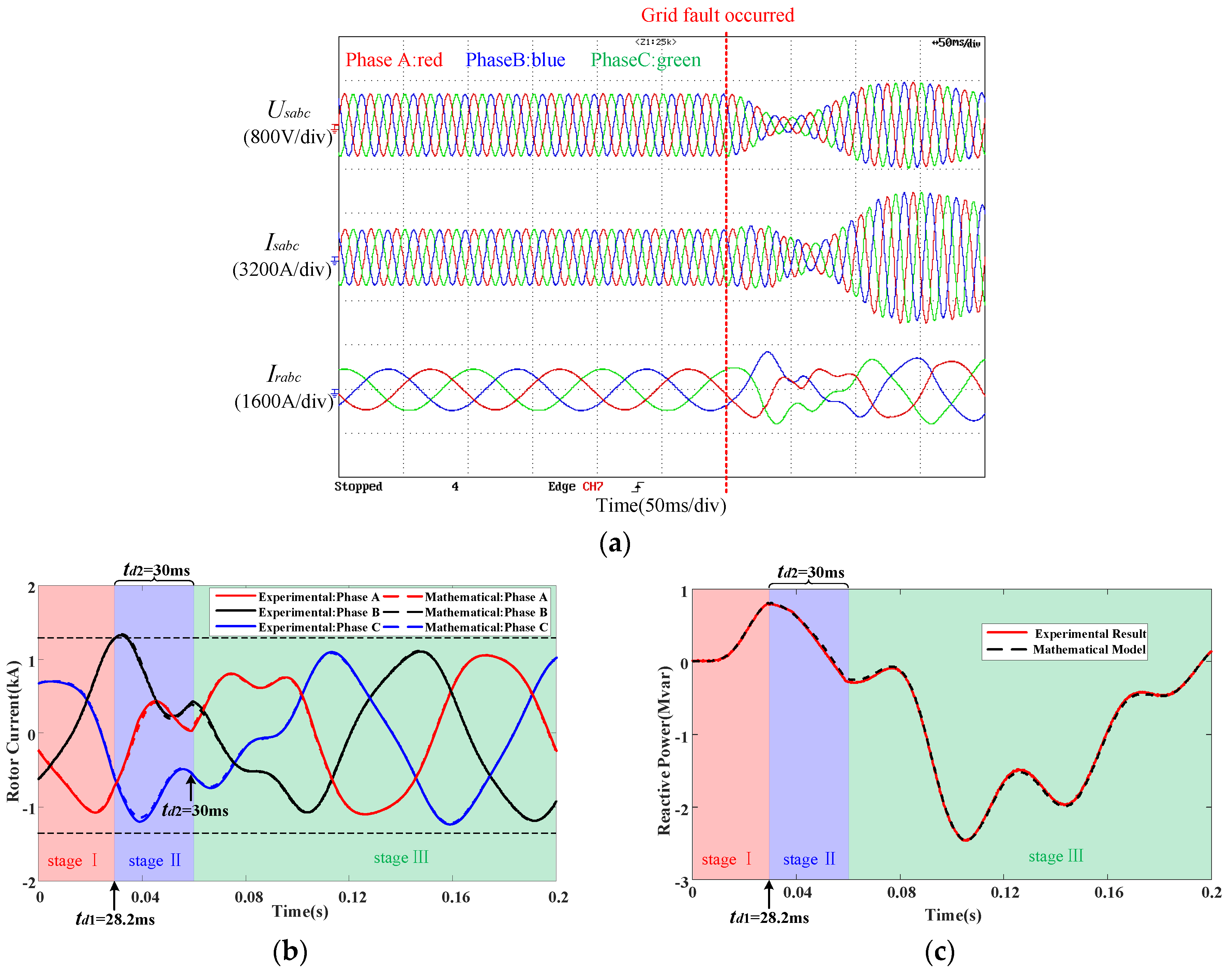
Figure 9 shows the grid voltage waveform under commutation fault.
Figure 10 shows the experimental results under commutation failure.
Figure 10a shows the experimental waveform of stator voltage, the stator current, and rotor side current. According to the experimental results, the crowbar of DFIG will be triggered under commutation failure. The background color of each stage is the same as that shown in
Figure 7.
The comparison between the experimental result and calculation result of the rotor current under commutation failure is shown in
Figure 10b. The comparison between the experimental result and calculation result of the transient reactive power under commutation failure is shown in
Figure 10c.
According to
Figure 10b, the rotor current error is less than 5% of the rated rotor current during the entire transient process. According to
Figure 10c, the power error of DFIG is less than 4% of the rated power during the entire transient process. The proposed mathematical model can accurately calculate the reactive power characteristics of DFIG under commutation failure.
Whether step-down faults or non-step faults, the maximum error between mathematical model results and experimental results is less than 5% of the rated value. The established transient mathematical model of the DFIG system considering crowbar circuit is highly accurate.
4. Analysis of DFIG Transient Reactive Characteristics under Commutation Failure
Based on the transient reactive power mathematical model of DFIG in
Section 2, the reactive power characteristics of DFIG under grid voltage faults can be quickly and accurately calculated. The influence of the system parameters on the transient reactive power of DFIG can also be analyzed, which can provide theoretical basis for the transient characteristics analysis of DFIG and the selection of crowbar parameters for various grid faults including commutation failure faults.
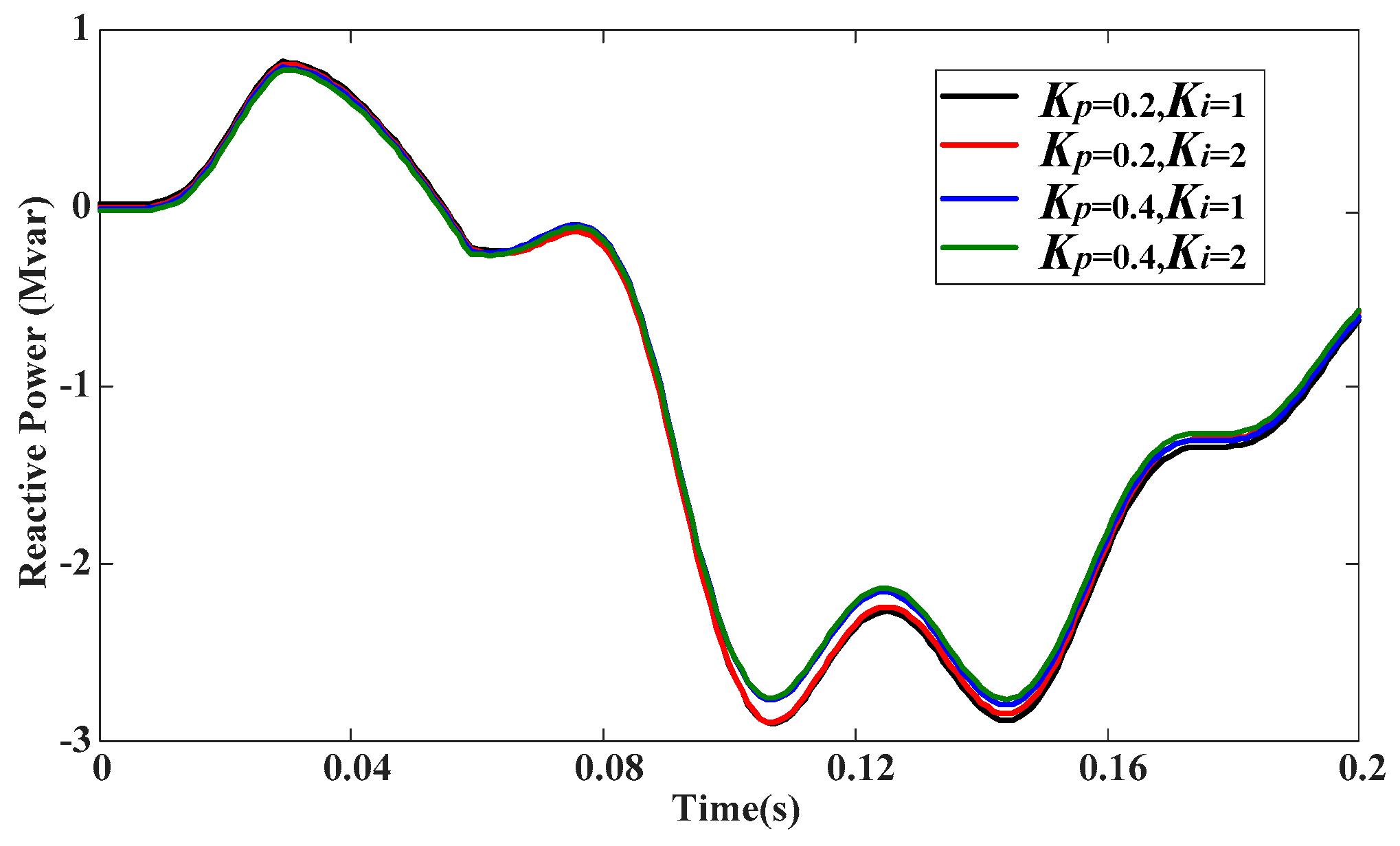
In the case of commutation failure fault, the grid voltage does not change rapidly, as shown in
Figure 9. Therefore, the rotor currents of DFIG can follow the reference values due to the closed loop control of rotor current. The reactive power of the DFIG output will be unaffected by the current loop parameters of RSC.
Figure 11 shows the transient reactive characteristics of DFIG under different RSC parameters. It can be seen that the parameters of RSC current loop have little effect on the reactive characteristics of DFIG.
The selection basis of crowbar resistance value should be investigated based on two points. One is that the rotor current should not exceed the safe value of the rotor current when the crowbar is triggered. The second is that the peak value of the rotor line voltage should be smaller than the DC bus voltage to avoid reverse charging of the fast recovery diode in the RSC to the DC bus capacitor. When the grid voltage drops to 0 in the worst condition, the peak value of the rotor current reaches the maximum [
21,
22], which can be expressed as:
Firstly, the crowbar resistance should be large enough to suppress the rotor current of the DFIG under the fault. The limit of the maximum rotor current to the crowbar resistance can be expressed as:
Secondly, the line voltage on the rotor side should be less than the DC bus voltage value, which can be expressed as:
where
Vdc is the rated voltage of the DC bus.
According to (29) and (30), Rcowbar should be selected in 0.35~0.40 Ω. In order to ensure that the LVRT capability of DFIG is not affected, the value of the crowbar resistance under commutation failure should not exceed this range.
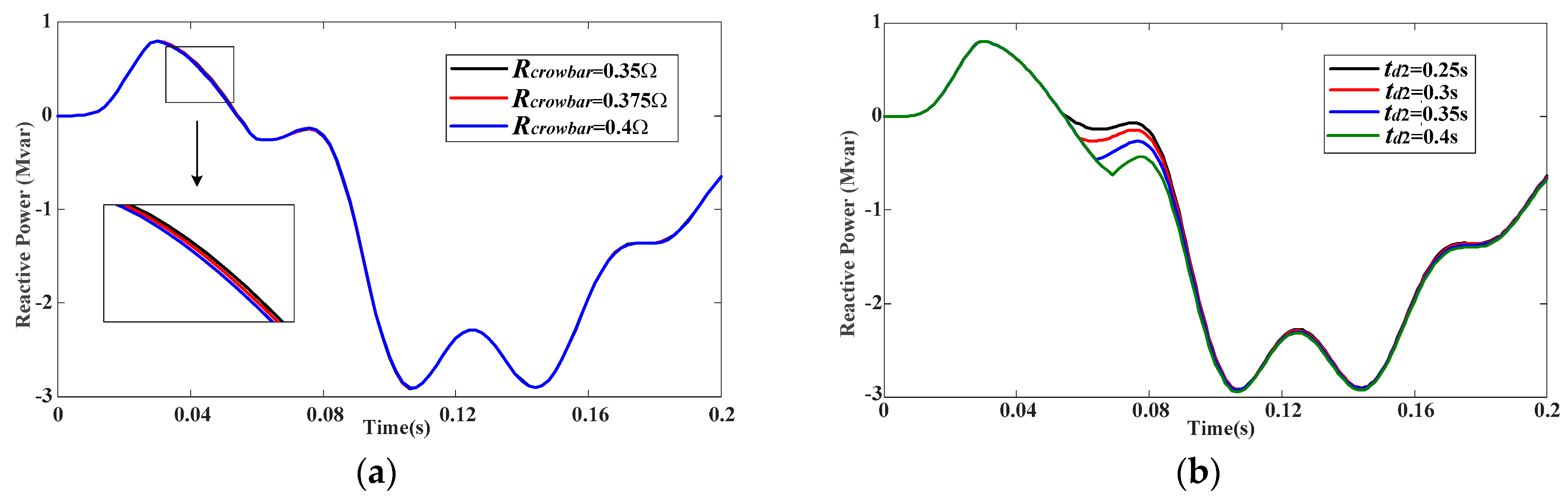
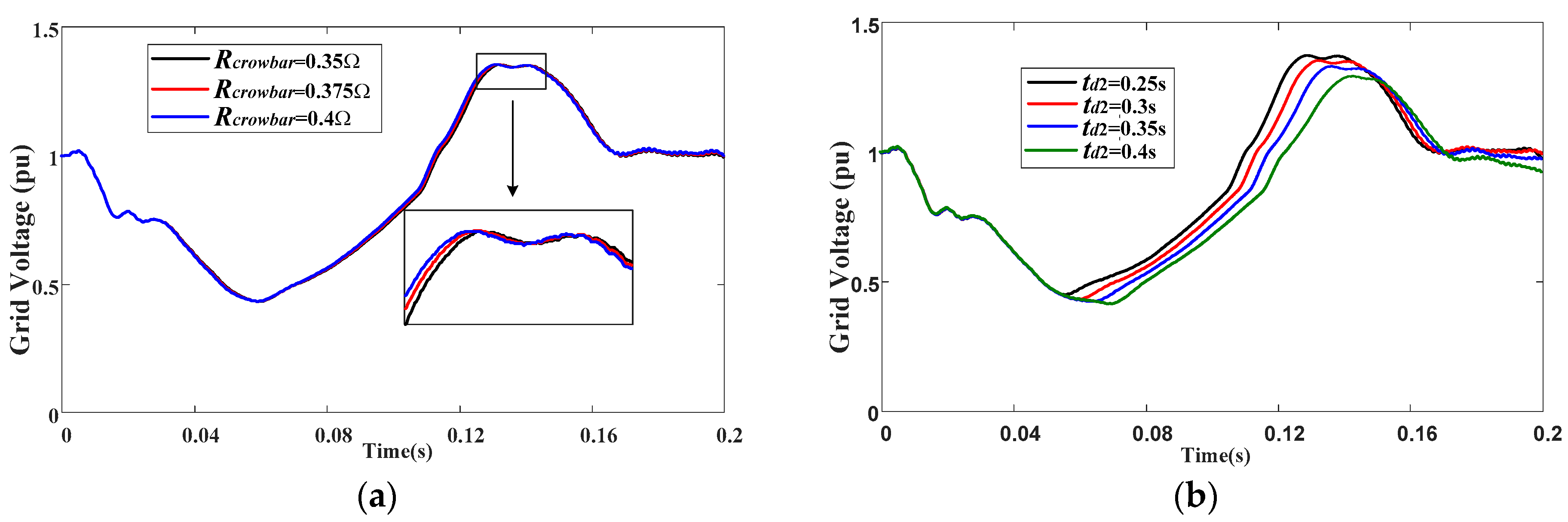
Figure 12 shows the mathematical model calculation results of DFIG output reactive power under different crowbar resistor values and different crowbar activation times in the case of the commutation failure.
According to
Figure 12a, it can be seen that changing the resistance value of the crowbar will only affect the transient process of the stage in which the crowbar is triggered (stage II) and the stage in which the crowbar is disconnected (stage III), and does not affect the duration of each stage. Because the allowable range of crowbar resistance value is limited, choosing different crowbar resistor values has little effect on the transient reactive power of DFIG. According to
Figure 12b, changing the activation time of the crowbar affects the duration of stage II and stage III. The RSC control does not work in stage II, and the rotor current maintains a small value under the action of the crowbar resistance. In stage III, the rotor current is controlled by RSC, and the command value of the rotor current is the same. Therefore, the reactive power of the DFIG varies greatly from stage II to stage III under different activation times of the crowbar, and then the reactive power of the DFIG tends to be the same under the control of RSC. Selecting a larger activation time
td2 of crowbar can reduce the reactive power output of the DFIG.
For the grid with high wind power penetration rate, changing the transient reactive power of DFIG can effectively adjust the overvoltage of the sending ac grid under commutation failure fault [
23,
24]. Therefore, changing the crowbar parameters of DFIG is an effective solution to suppress the over-voltage peak of the sending ac grid under commutation failure fault.
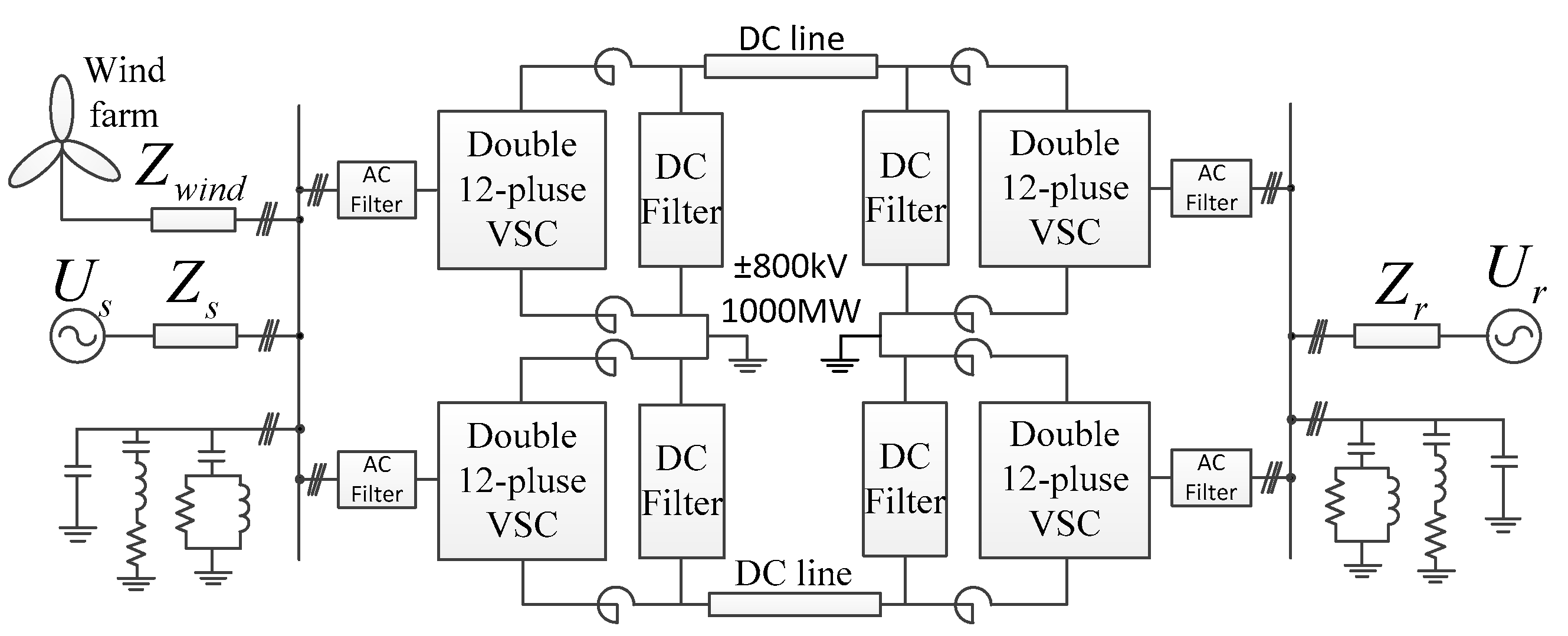
According to the actual situation of the ±800 kV QISHAO UHVDC engineering in China, the UHVDC transmission system with rated transmission power of 1000 MW is established based on Matlab/Simulink. The power of the wind farm in the sending ac grid accounts for 75%.
Figure 13 shows the topology of the wind farm connected to UHVDC system [
25].
Under the condition that the control of the sending-side converter station is kept unchanged,
Figure 14 shows the amplitude of AC bus voltage in the sending ac grid under different crowbar parameters in the case of the commutation failure. According to
Figure 14a, the peak value of the transient overvoltage is about 1.35 pu. Choosing different crowbar resistor values has little effect on the transient reactive power of DFIG. According to
Figure 14b, the peak values of transient overvoltage are 1.37, 1.35, 1.33, and 1.29 pu, respectively. Therefore, the peak value of transient overvoltage in the sending ac grid can be reduced by selecting a larger activation time td2 of crowbar.


