Article

Fuzzy Logic Approach to Dissolved Gas Analysis for Power Transformer Failure Index and Fault Identification

by
Nitchamon Poonnoy
1,
Cattareeya Suwanasri
1,* and
Thanapong Suwanasri
2
1
Department of Electrical and Computer Engineering, Faculty of Engineering, King Mongkut’s University of Technology North Bangkok (KMUTNB), Bangkok 10800, Thailand
2
Department of Electrical and Software Systems Engineering, The Sirindhorn International Thai-German Graduate School of Engineering (TGGS), KMUTNB, Bangkok 10800, Thailand
*
Author to whom correspondence should be addressed.
Energies 2021, 14(1), 36; https://doi.org/10.3390/en14010036
Submission received: 12 November 2020 / Revised: 14 December 2020 / Accepted: 20 December 2020 / Published: 23 December 2020
(This article belongs to the Section F: Electrical Engineering)

Abstract

:
This research focuses on problem identification due to faults in power transformers during operation by using dissolved gas analysis such as key gas, IEC ratio, Duval triangle techniques, and fuzzy logic approaches. Then, the condition of the power transformer is evaluated in terms of the percentage of failure index and internal fault determination. Fuzzy logic with the key gas approach was used to calculate the failure index and identify problems inside the power transformer. At the same time, the IEC three-gas ratio and Duval triangle are subsequently applied to confirm the problems in different failure types covering all possibilities inside the power transformer. After that, the fuzzy logic system was applied and validated with DGA results of 244 transformers as reference cases with satisfactory accuracy. Two transformers were evaluated and practically confirmed by the investigation results of an un-tanked power transformer. Finally, the DGA results of a total of 224 transformers were further evaluated by the fuzzy logic system. This fuzzy logic is a smart, accurate tool for automatically identifying faults occurring within transformers. Finally, the recommendation of maintenance strategy and time interval is proposed for effective planning to minimize the catastrophic damage, which could occur with the power transformer and its network.

1. Introduction

The power transformer is a key component in power transmission and distribution systems. During operation, it might be deteriorated by both normal and abnormal conditions, including overloading, aging, and degradation of paper-oil insulation, internal arcing and partial discharge (PD), short circuit, etc. Survey results [1] show damages within power transformers including on-load tap changer (OLTC), winding and iron core, bushing, tank, and other related damages. Therefore, to prevent failure and to maintain the power transformer in the satisfactorily working condition, several traditional and nontraditional diagnostic methods have been performed to assess the condition [2,3]. The traditional diagnostic methods are dissolved gas analysis, oil quality, power factor testing, winding resistance measurement, turn ratio, and thermography, while the nontraditional diagnostic methods are partial discharge measurement, dielectric spectroscopy, frequency response analysis, tap changer monitoring, and internal temperature measurement. After obtaining the test results from various diagnostic methods mentioned above, the data has been further evaluated to assess the condition of the power transformer, mainly based on health index value by applying a scoring and weighting algorithm [4]. However, this traditional health index determination has some drawbacks because it requires many test results from transformer electrical tests and oil diagnostics to complete the evaluation process, as well as the influence of weight determination on the uncertainty of the obtained health index result [4].
Several defects can occur with a power transformer and lead to a shorter transformer life, malfunction, unplanned outage, etc., which directly affect the increase in the amount of specific gases dissolved in insulating oil within the transformer tank, such as methane (CH4), ethane (C2H6), acetylene (C2H2), and ethylene (C2H4), as well as other gases such as carbon monoxide (CO), carbon dioxide (CO2), and hydrogen (H2). The dissolved gas analysis (DGA) with insulating oil can be implemented to identify the condition, interpret faults, and provide early warning of some problems inside the transformer. Many DGA techniques are widely used to diagnose significant faults; those techniques include electrical discharges, PD, electrical arcing, and thermal fault [5,6,7,8]. Reference [9] proposes the failure analysis based on the dissolved key gas concentration, total dissolved combustible gases (TDCG), and key gas. In [10], the Dörnenburg ratio method was introduced to classify the occurring problem as overheating, electrical discharge, and arcing. In [11], the Rogers ratio method was suggested to identify six fault types occurring in the insulating oil. In [12], IEC gas ratio was proposed to determine PD of high energy, low and high energy discharge, and thermal faults, however, it did not identify failure by paper insulation because it ignored CO and CO2. In [13,14,15,16], the Duval triangle technique was proposed to investigate the causes of faults and failure causes. In [17,18,19,20,21], most of the methods performed DGA with a simple tool to find out the incipient fault. However, it is inconvenient and time-consuming for industrial applications due to the complex analytical process. Hence, artificial intelligence techniques have been proposed to develop more accurate diagnostic tools based on DGA data [22]. In [23,24,25,26,27,28,29,30,31,32], some artificial intelligence techniques such as fuzzy logic, artificial neural network and support vector machines have been introduced for fault classification with nearly equal performance without determination of problem severity. Moreover, the artificial neural network technique requires a huge amount of data for training to make it recognize the fault types with less knowledge on the evaluation process. The fuzzy logic method is also an effective method developed to determine the answer, where the boundary is not explicit. It operates by designing the membership function and fuzzy sets appropriated to a specific problem. The most important step is tuning on ranges of the proposed fuzzy sets to obtain the correct answer with logical reason leading to a precise output. Therefore, the fuzzy logic has been adopted for DGA and fault severity analysis in this work.
As a result, this paper adopts and purposes the fuzzy logic approach to three DGA methods: key gas, IEC ratio, and Duval triangle methods to identify possible faults inside the power transformer such as overheat oil and paper, partial discharge, and arcing classified precisely into different ranges of severity. Moreover, the proposed fuzzy logic applied to the key gas method is a novelty used to determine failure index (%FI) and to identify the severity of faults, facilitates the specification of the proper maintenance actions to prevent the failure. In addition, the proposed combination of IEC ratio and the Duval triangle method is implemented to improve the ability of fault determination up to ten possible faults inside the power transformer. With these proposed fuzzy logic techniques with simulation software, this power transformer diagnostic system is faster, more accurate, and less time-consuming. The DGA test results of 112 power transformers were examined, while two power transformers were thoroughly investigated concerning their internal components.

2. Dissolved Gas Analysis

Three DGA methods including key gas, IEC ratio, and the Duval triangle method were used to investigate abnormality and fault inside a power transformer. In this paper, three DGA methods were simultaneously applied together to diagnose different faults within power transformers for more accurate and reliable results. However, before applying the three mentioned methods, one of the key gases must fall into condition “2” as a moderate condition of the dissolved key gas concentration limit technique [9] as shown in Table 1, otherwise, the fault investigation will not be requested. The dissolved key gas concentration limit technique can identify the severity of faults as good, moderate, poor, and bad condition.

2.1. Key Gas Analysis

The key gas method [9] was used to identify faults inside the power transformer. Key gases included H2, C2H6, C2H2, C2H4, CH4, CO, and CO2. Pairs of key gases indicated four types of faults, as shown in Table 2, such as overheat cellulose, overheat oil, electrical arcing, and PD.

2.2. IEC Ratio Method

IEC ratio method [11,13] applies three gas ratios C1, C2, and C3, as written in Equation (1). The ranges of each ratio are specified taking into account different types of faults, including PD, low energy discharge, high energy discharge, thermal fault temperature lower than 300 °C, thermal fault between 300 to 700 °C, and thermal fault temperature greater 700 °C. The ranges and faults are expressed in Table 3.
C 1   =   C 2 H 2 C 2 H 4 ,   C 2   =   CH 4 H 2 ,   C 3   =   C 2 H 4 C 2 H 6

2.3. Duval Triangle Method

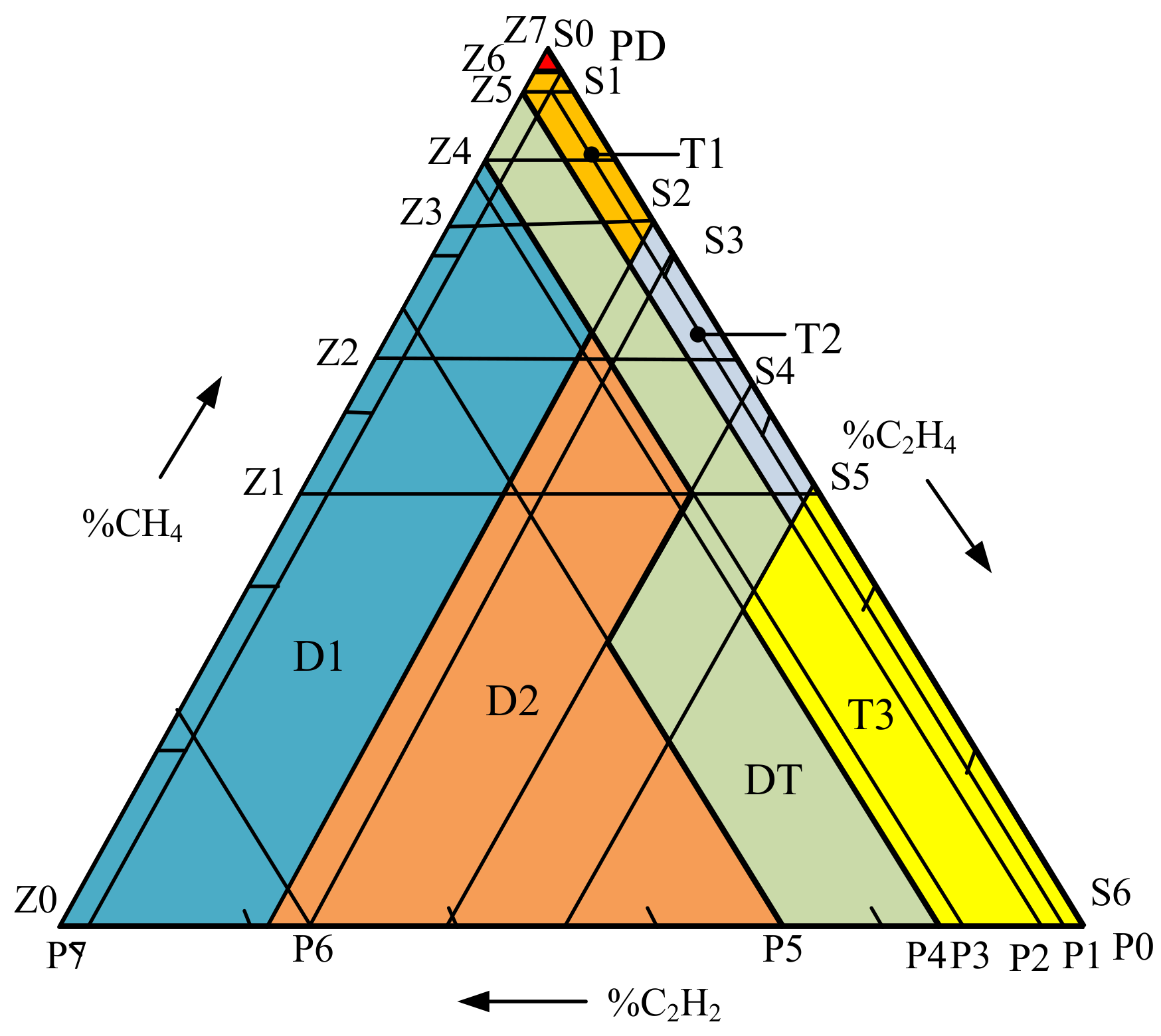
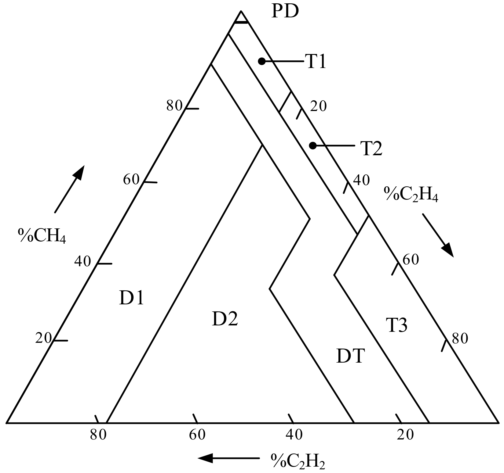
The conventional Duval triangle method [13,14,15,16] applies only three gases, which are CH4, C2H4, and C2H2, for determining faults in the transformer by using the percentages of %CH4, %C2H4, and %C2H2 as written in Equation (2). The coordination of the three percentages is then plotted on the Duval triangle as presented in Figure 1. For example, %CH4 is firstly marked along the left-axis while %C2H4 is then marked along the right-axis. Finally, %C2H2 is marked along the x-axis. The coordination of %CH4, %C2H4 and %C2H2 are plotted together to obtain the type of failures.
The area in the Duval triangle is divided into seven zones identifying seven faults such as corona PD, low energy discharge, high energy discharge, thermal fault temperature less than 300 °C, thermal fault temperature between 300 to 700 °C, thermal fault temperature greater than 700 °C, and lastly, mixed thermal and electrical fault as illustrated in Table 4. This method provides highly accurate results. However, the technique ignores H2 and C2H6, which limits its ability in fault detection when the faults have progressively formed. Consequently, the key gas and IEC method are also needed.
% CH 4 = CH 4 CH 4 + C 2 H 2 + C 2 H 4 × 100 ,   % C 2 H 2 = C 2 H 2 CH 4 + C 2 H 2 + C 2 H 4 × 100 ,   % C 2 H 4 = C 2 H 4 CH 4 + C 2 H 2 + C 2 H 4 × 100

3. Fuzzy Logic for Insulating Oil Condition Assessment

The fuzzy logic approach is a computerized calculation tool [24,25,26,27] generally used to simulate expert knowledge, experience, and automatic judgment without human action. In this paper, fuzzy logic was applied with three DGA methods as key gas, IEC gas ratio, and the Duval triangle method to analyze faults inside power transformers. Fuzzy logic based triangular membership function(trimf) was defined in different levels in the fuzzy logic approaches to the IEC gas ratio and Duval triangle method as written in Equation (3), while fuzzy logic-based two-Gaussian membership function (gauss2mf), as written in Equation (4), approaches to the key gas method. The original input of each technique is amount of key gases in ppm. A fuzzy rule-based system is developed to specify faults. The Mamdani fuzzy inference system was applied to differentiate results by eliminating ambiguity. A defuzzifier based center of gravity (COG) method was used to interpret and display the results into numbers (i.e., 1, 3, 5, …) that were then assigned to different faults (i.e., F1, F2, F3, …).
f ( x ; a , b , c ) = 0 , x a x a b a , a x b c x c b , b x c 0 , c x ,
where f ( x ; a , b , c ) is the output curve of the trimf, and x is input gases in ppm. The values of parameters a, b, and c are specified to identify the range of the triangular membership function.
f ( x ; σ , c ) = e ( χ c ) 2 2 σ 2
where f ( x ; σ , c ) is the output curve of the gauss2mf, and x is input gases in ppm. Similarly, the values of σ and c are specified to identify the range of the two Gaussian membership functions.
Defuzzification based on the center of gravity (COG) method was used to determine a defuzzified output as written in Equation (5).
z * = z μ ( z ) d z μ ( z ) d z
where z is the output curve applied for both triangular membership function and two Gaussian functions, µ(z) is the membership function of the defuzzification, and z* is the defuzzified fuzzy output.

3.1. Application of a Fuzzy Logic Approach to the Key Gas Method

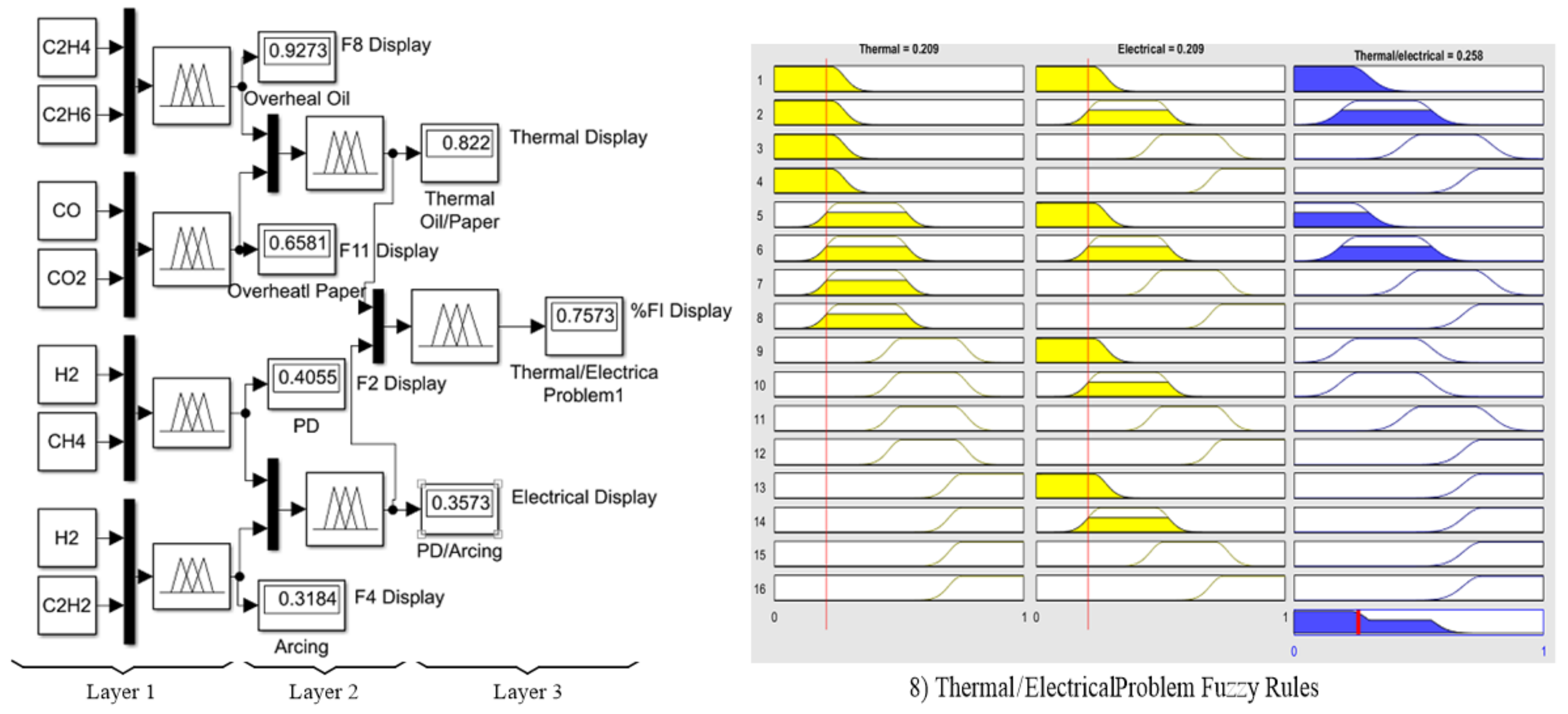
In this paper, a combination of the two-Gaussian membership function in Equation (4) was applied to the DGA using the key gas method [9]. The advantage of this method can be explained by the fact that there are overlapping areas, which are applied to identify the percentage of failure index (%FI). The 3-layer fuzzy logic model with 16 fuzzy rules was proposed and expressed in Figure 2 (left), while the shapes of the 16 fuzzy rules are shown in Figure 2 (right). To obtain a precise result, the input ranges of seven input gases were identified according to Table 2, while four output ranges of the output function were identified in Table 5. The Fuzzy output codes and faults are then determined as written in Table 6. Finally, the proposed defuzzification with COG method in Equation (5) was applied to calculate %FI, referring to the power transformer condition as written in Table 7, which can be differentiated into three color bands as red, yellow, and green.
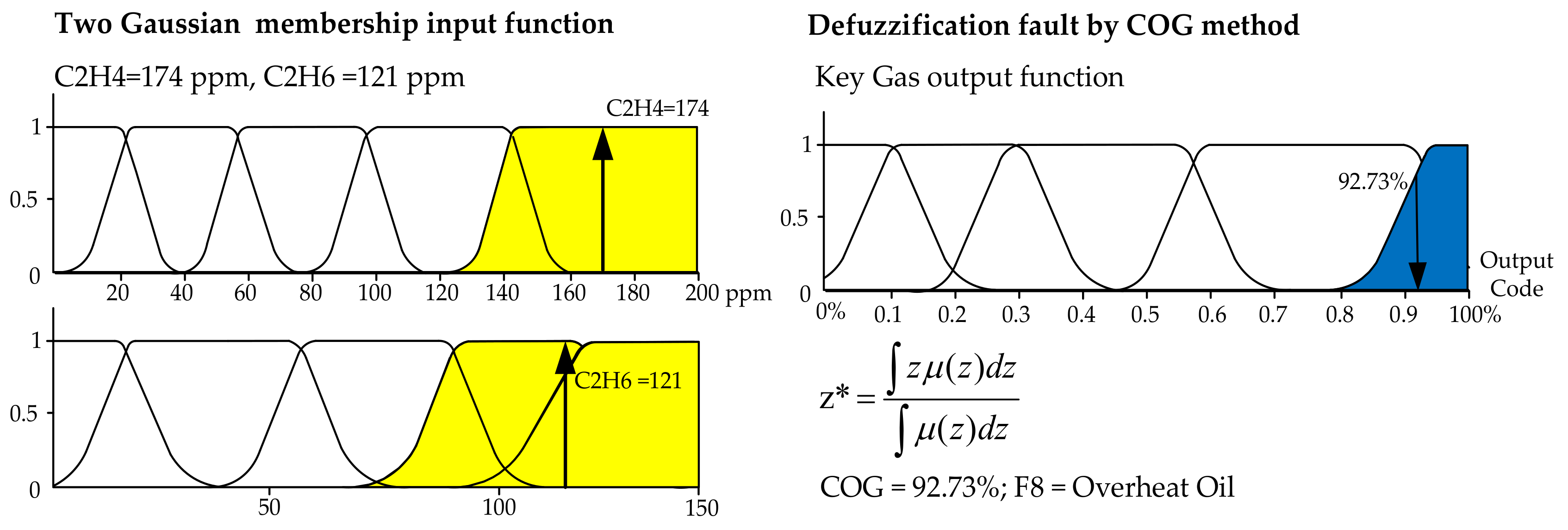
Figure 3 shows the two-Gaussian membership fuzzification and defuzzification procedure according to Equations (3) and (5), respectively. In Figure 3 (left), for the first layer, two couples of key gases as CO and CO2, C2H4 and C2H6, CH4 and H2, as well as C2H2 and H2 as the inputs were compared to indicate %FI, while all four ranges of inputs are defined. In Figure 3 (right), the types of faults in Table 1 as outputs are defuzzified and decoded as F8 representing an overheating oil problem with 92.73% fault possibility. Similar to the 2nd layer, the couples F2 and F4 as well as F8 and F11 were further compared, resulting to the possibility of 82.2% as a thermal problem and 35.73% as an electrical problem. Finally, in the 3rd layer, %FI was then calculated as equal to 75.73%.

3.2. Application of the Fuzzy Logic Approach to IEC Ratio Method

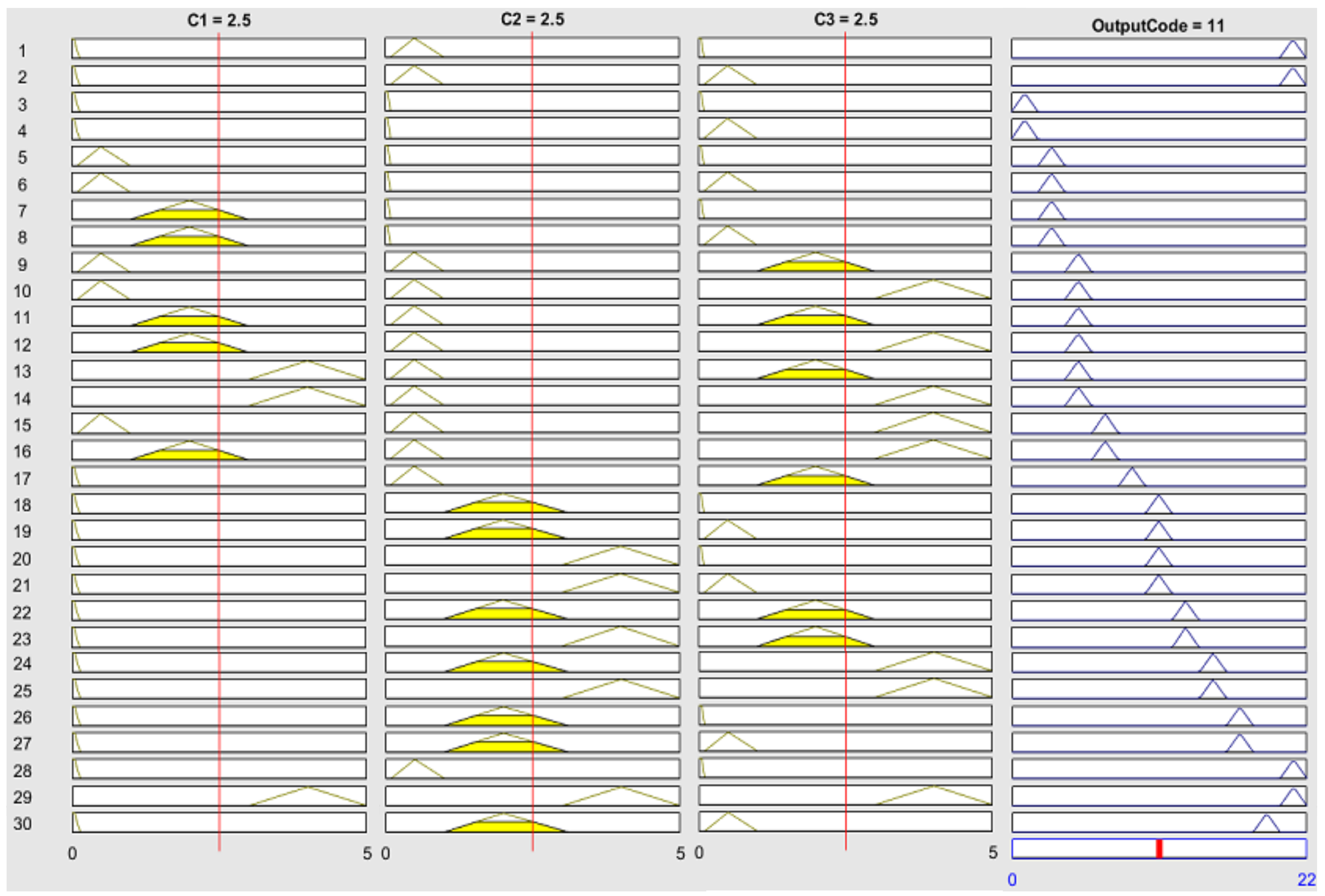
In this paper, the triangular membership, as in Equation (3) and in Figure 4, was applied to IEC ratio method [13,14,15,16] because of the explicit ranges of input conditions as low, medium, high, and very high resulting in easy interpretation. According to the model, ratios C1, C2, and C3 in Equation (1) were first calculated. Then, the calculated result defined as “ U ” is the input of this membership function, as shown in Table 8. A single-layer fuzzy model was then applied. Thirty fuzzy rules were proposed to identify possible faults, as shown in Figure 4. The output code is represented by the numbers 1 to 21. Similarly, the defuzzification with the COG method is then applied. Nine faults are possible and written in the form of malfunction as given in Table 9.
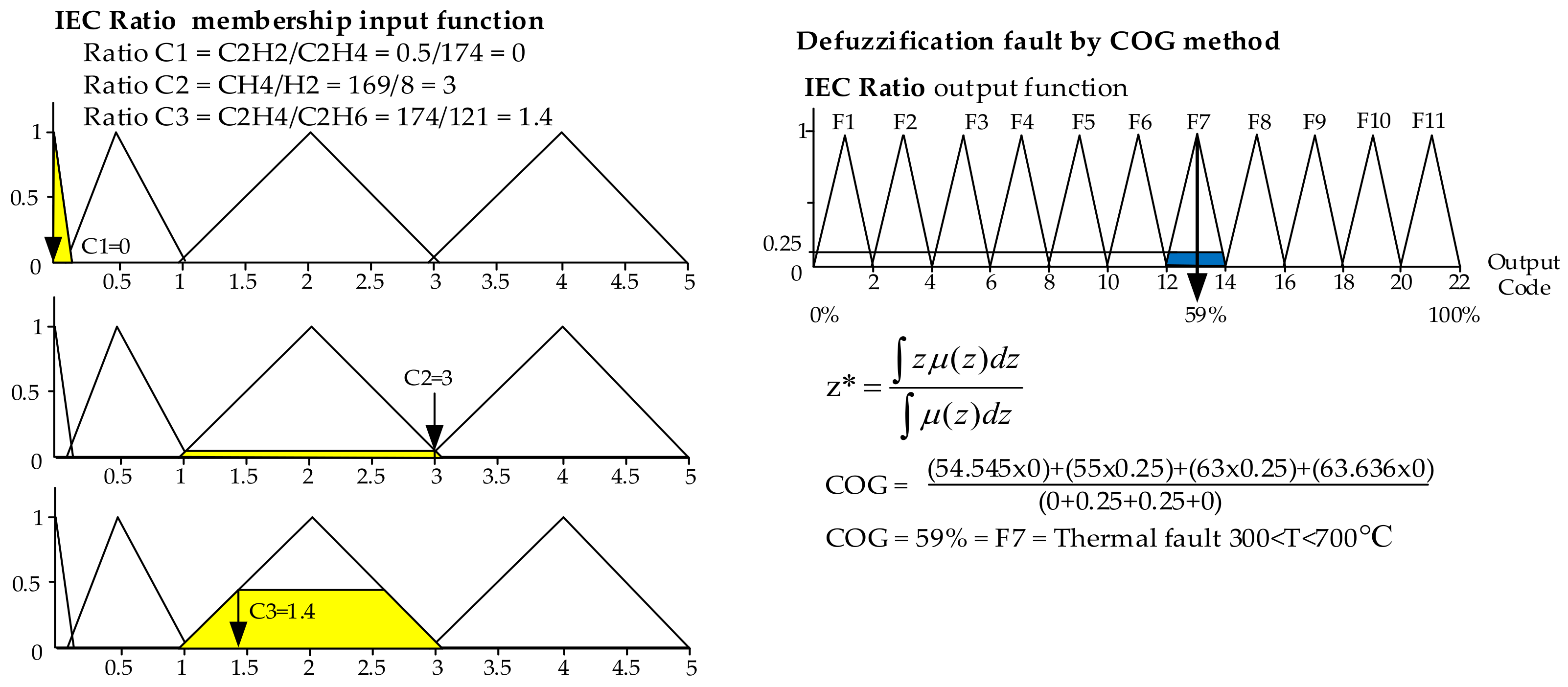
For the IEC Ratio method, Figure 5 shows the first layer of triangle membership function fuzzification and defuzzification procedure according to Equations (3) and (5), respectively. In Figure 5 (left), ratios C1 = 0, C2 = 3, and C3 = 1.4 were calculated by using Equation (1) and represented as inputs in Equation (3). The four ranges of each input were defined, as shown in Figure 5 (left). The types of faults as output are defuzzified as equal to 59% and decoded as F7 representing thermal fault problem (T2; 300 < T < 700 °C) as written in Figure 5 (right).

3.3. Fuzzy Logic with Duval Triangle Method

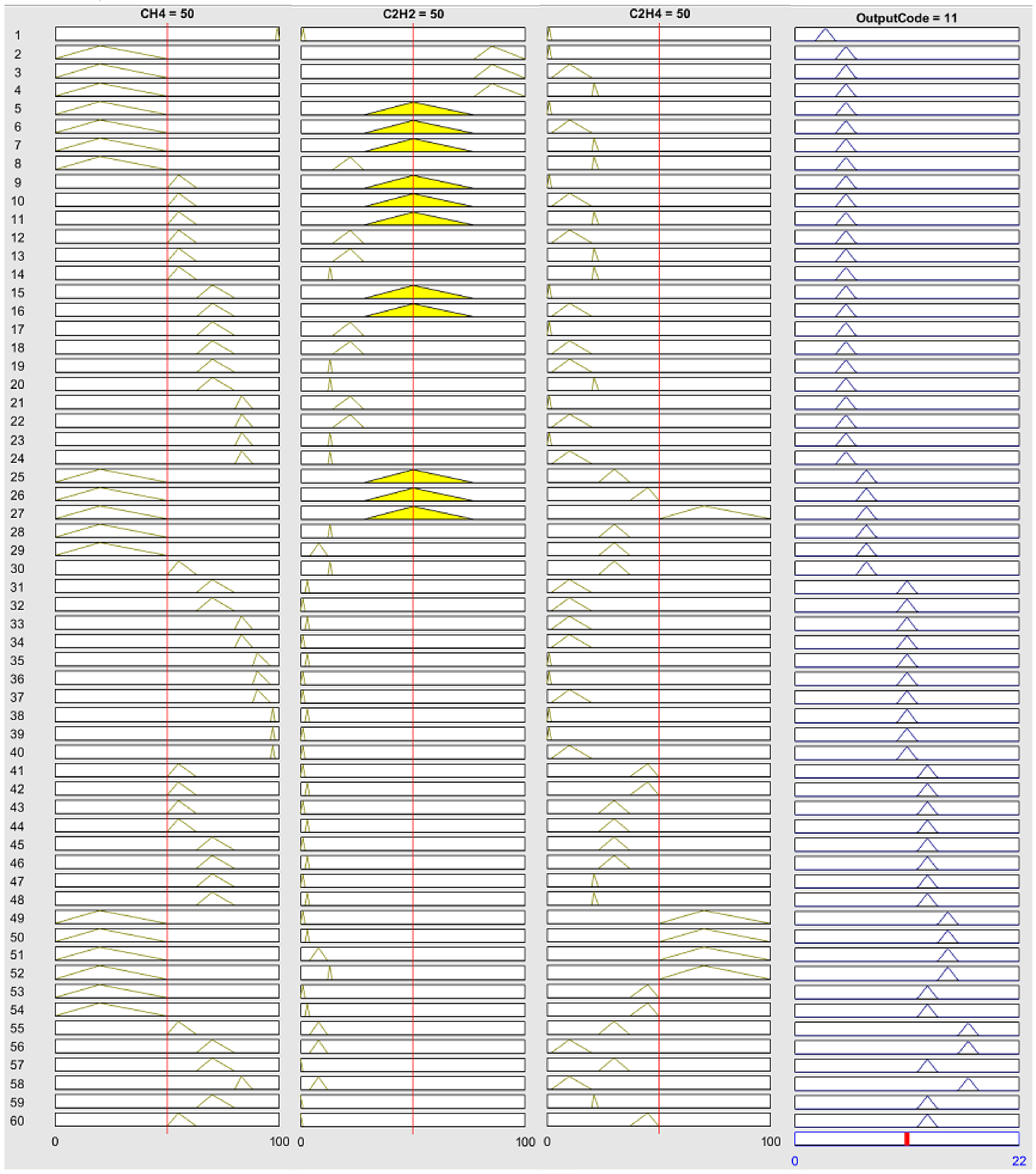
The triangular membership function is applied to the Duval triangle method [11,12,13,14] because of the explicit ranges of the input with the most simple output code interpretation, as written in Table 10. The percentages of ratio %CH4, %C2H4, and %C2H2 defined as Z, P, S parameters classified in different zones as written in Equation (6) are the inputs of the membership function for plotting in the Duval triangle as presented in Figure 6. Similarly, a single-layer fuzzy model was applied. Sixty fuzzy rules were identified for possible faults, as shown in Figure 7. Similarly, the output code was represented by numbers (1 to 21). The defuzzification with COG method was then applied. The eight fault types identified by the Duval triangle method are written in Table 10.
% C H 4 = Z 1 ; Z < 50 Z 2 ; 50 Z < 63 Z 3 ; 63 Z < 80 Z 4 ; 80 Z < 88 Z 5 ; 88 Z < 98 Z 6 ; Z 98 ,   % C 2 H 2 = P 1 ; P < 2 P 2 ; 2 P < 4 P 3 ; 4 P < 12 P 4 ; 12 P < 14 P 5 ; 14 P < 28 P 6 ; 28 P < 77 P 7 ; P 77 ,   % C 2 H 4 = S 1 ; S < 2 S 2 ; 2 S < 20 S 3 ; 20 S < 23 S 4 ; 23 S < 37 S 5 ; 37 S < 50 S 6 ; S 50
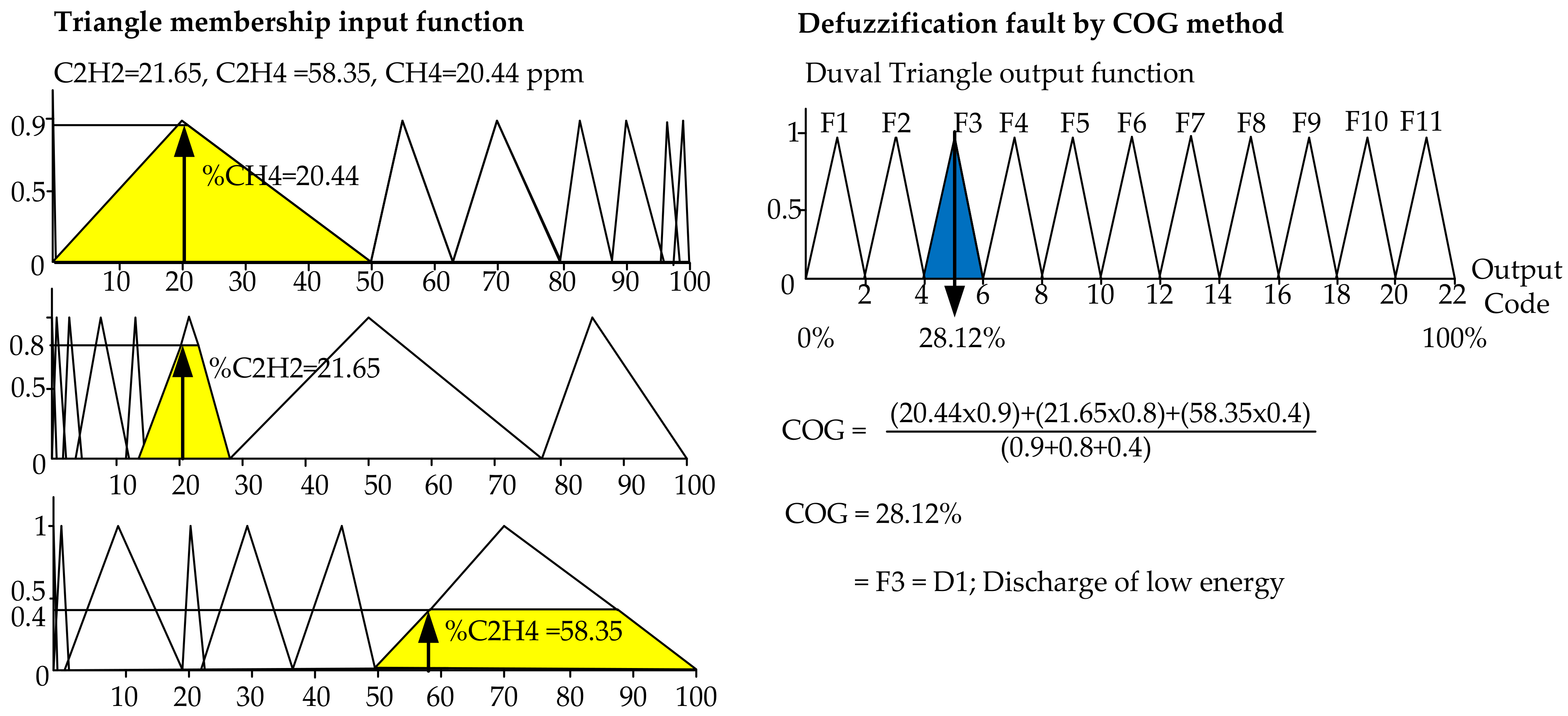
Figure 7 shows the fuzzy logic fuzzification and defuzzification procedure for the Duval triangle method by using Equations (3) and (5), respectively. The %CH4, %C2H4, and %C2H2 were calculated as equal to 20.44, and 21.65, 58.35%, which are defined as Z, P, S parameters. The ranges of Z, P, S in Equation (6) are also drawn in Figure 8 (left), while the COG was calculated by using fuzzy logic defuzzification and equal to 28.12% as shown in Figure 8 (right), which falls into F3 decoded to D1 as the discharge of low energy.

3.4. Defuzzified Faults from Three Fuzzy Logic Methods

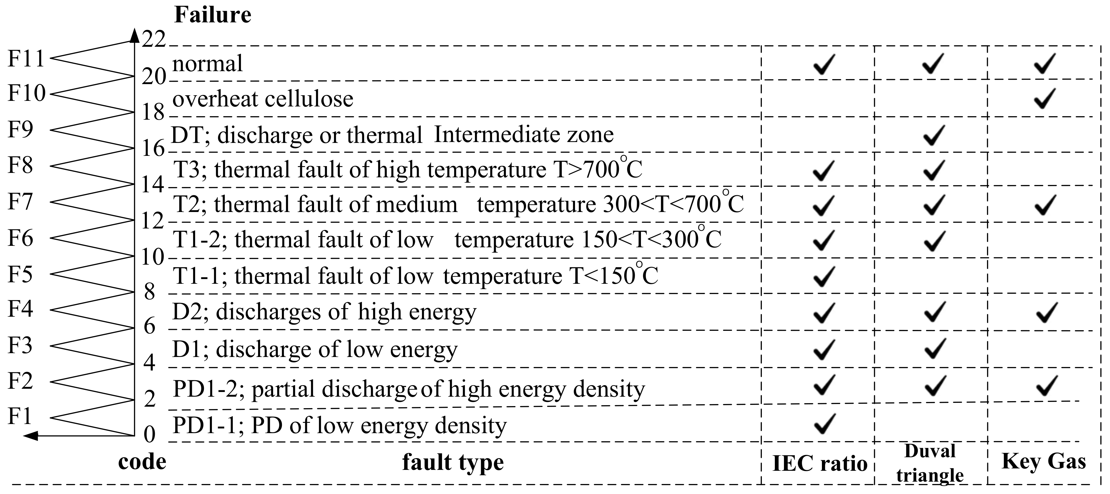
The proposed defuzzified codes from 1–21, representing eleven faults from three fuzzy logic methods and the key gas, IEC Ratio, and the Duval triangle method were compared, as shown in Figure 9. For example, the defuzzified values between range 2–4 shows the faults as PD1-2 as the partial discharge of high energy density, exactly determined by all three methods. All methods should be simultaneously applied to precisely identify the failure inside the power transformer.

4. Results and Discussions

4.1. Fuzzy Logic Implementation to Practical Two Un-Tanked Power Transformers

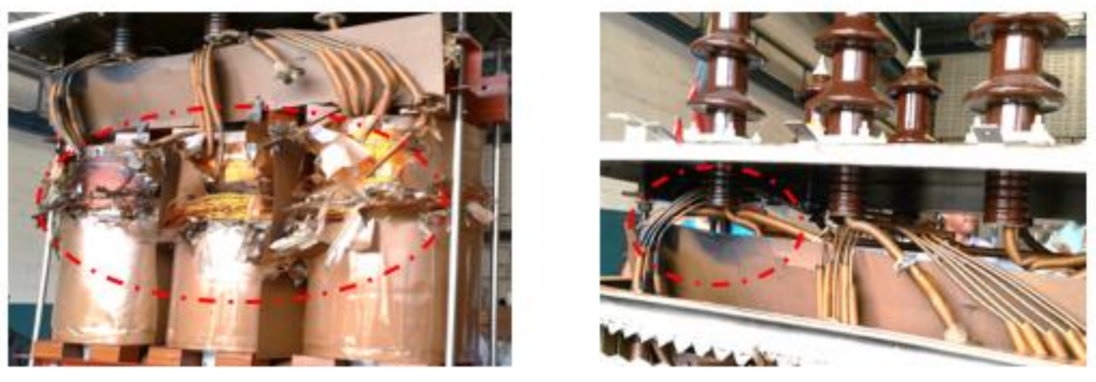
DGA results of two power transformers named as TR1 and TR2 obtained from certified DGA laboratory with ratings 115/69 kV, 15 MVA and 22 kV/416 V, 3 MVA, respectively with un-tanked investigation after failure [18] were analyzed and interpreted for problems occurring within paper and oil insulation of these transformers, as given in Table 11. The faults identified by three fuzzy logic approaches are shown in Table 12. All methods by Fuzzy Logic confirmed the arcing inside the power transformer recognized from the abnormal amount of C2H2, as well as obvious pictures from the internal investigation, as shown in Figure 10 and Figure 11.

4.2. Fuzzy Logic Implementation to 10 Power Transformers

Similarly, Table 13 shows practical DGA results of additional ten transformers named as TR3 to TR12 obtained from a certified DGA laboratory. By applying the TDCG method, TR5 encountered condition “2” that a fault could probably occur within the transformer. Transformers TR3 to TR12 (except TR5) encountered condition “3” indicating that some faults were identified. Then, the fuzzy logic was further applied to identify the types of defect.
The results of faults such as corona and PD, arcing, overheated oil, overheated cellulose/paper, and %FI were precisely identified by fuzzy logic with the key gas method as shown in Table 14. Transformer nos. 4, 5, 8, 9, 11, and 12 encountered high severe faults. Similarly, with the fuzzy logic approach to the IEC three-gas ratio and Duval triangle, the results are compared with key gas methods, as shown in Table 15. The results agree well between both analysis methods.

4.3. Model Validation of the Fuzzy Logic System with Three DGA methods

This paper proposed a fuzzy logic system for power transformer fault assessment based on the three DGA methods; key gas, IEC ratio, and Duval triangle method were validated with a population of 500 power transformers. The diagnosis DGA of 132 transformers taken from [30,33] as reference cases were first validated with accurate results. Then, DGA results of the total 112 power transformers with rating 115/22 kV in sub-transmission system of two electrical utilities were further validated with the developed fuzzy logic system. From these additional 112 cases, the raw DGA data of 2 un-tanked transformers is shown in Table 11 to confirm the obtained results with the evidence found, and 10 example cases are shown in Table 13 to demonstrate result consistency. Moreover, the additional raw DGA data of 100 cases were obtained from a certified DGA laboratory, and the fault types of 100 cases were first analyzed with standard diagnosis methods and subsequently used to validate the results from the developed fuzzy logic system. Table 16 presents a comparison of results from the fuzzy logic approach to three DGA standard diagnosis methods. The number of transformers was increased to 244 samples to improve the precision of the assessment.
In Table 16, the matched and unmated cases, as well as the percentage accuracy and error are given. The percentage error using fuzzy logic based key gas, IEC ratio, and Duval triangle methods was also calculated by dividing the numbers of unmatched units with the total tested units, which were equal to 82.37, 61.89, and 94.26%, resulting in a percentage accuracy of 80.33, 69.67, and 93.85%, respectively, as shown in Table 16. By applying the sampling theory, the statistical method mentioned in [34] estimated a 5% output error of the system when 244 data was tested out of 500 samples. The overall accuracy was further calculated by multiplying 95% accuracy from sampling theory to the obtained percentage accuracy. Lastly, the final percentage accuracy was calculated as 78.26, 58.79, and 89.54%, accordingly. This implied that the required number of tested DGA data should be more than 244 out of the total 500 populations to improve the accuracy with less than 5% error.
As presented in Table 16, the fuzzy logic approach with the Duval triangle method yielded the most accurate result with 89.54%. It was also clearly seen that the fuzzy logic approach with IEC ratio method could improve the drawbacks of the standard IEC ratio method as the obtained results agreed well with the Duval triangle method. Consequently, 79 fault types, which were unidentified by the conventional IEC method, were better classified by the fuzzy logic system. Moreover, the fuzzy logic approach to the key gas method was able to evaluate both the percentage of failure index and internal fault determination.

4.4. Graphical Circle Using Fuzzy Logic Approach to DGA Results for 100 Power Transformers

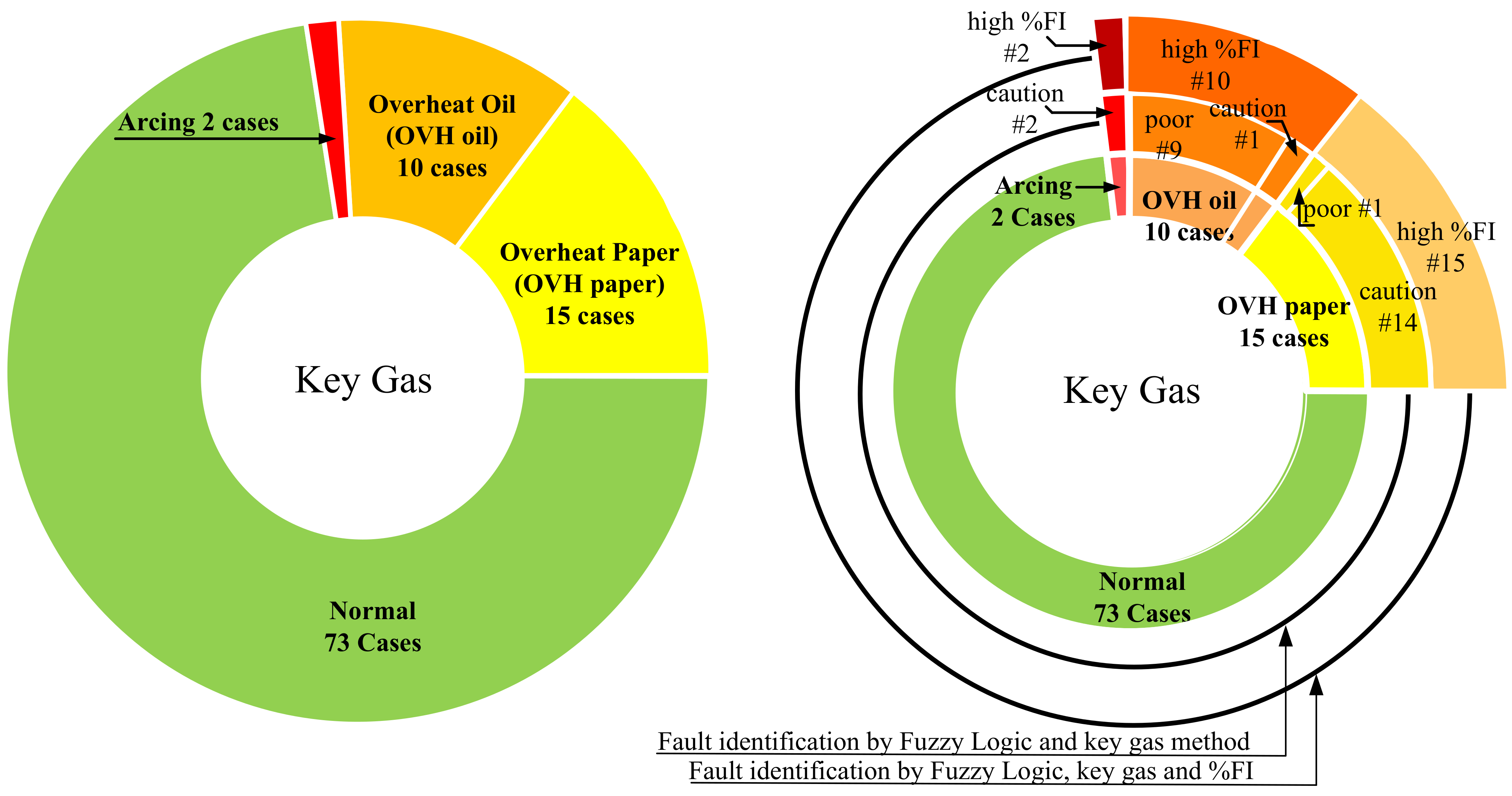
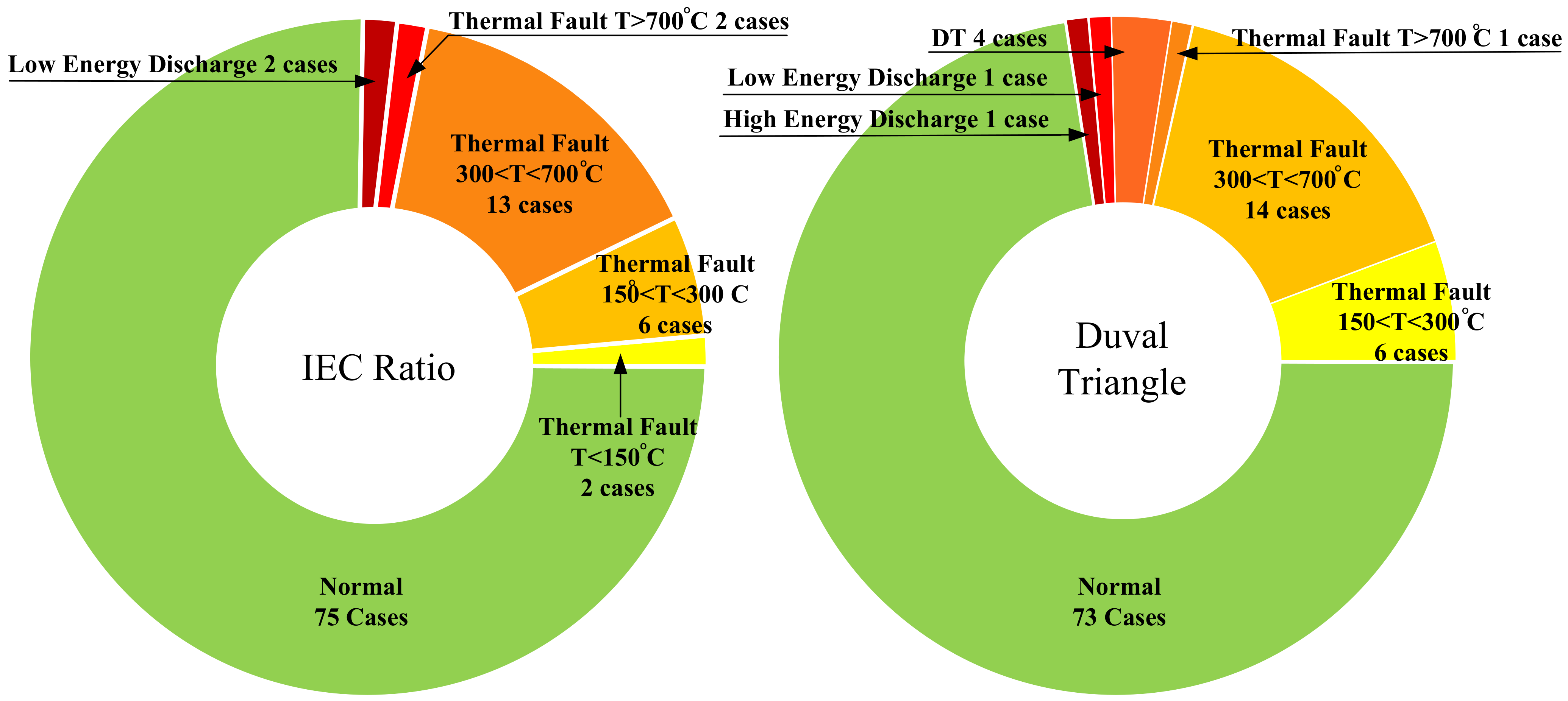
A graphical circle was implemented to clearly identify and compare the fault results analyzed by fuzzy logic with three DGA methods when the DGA of 100 power transformers in a utility was investigated. A certified laboratory validated the raw DGA data of these 100 transformers, and the fault types were determined by the standard diagnosis method. In Figure 12 and Figure 13, graphs of a 100 power transformer fleet in Thailand are presented as examples. Figure 12 (left) shows the numbers of four faults as of PD, OVH paper, OVH oil, and arcing, classified by the key gas method using standard diagnosis methods using an excel program. It showed that 15 and 10 transformers encountered OVH paper and oil, respectively. Whereas in Figure 12 (right), the numbers of four faults analyzed by the key gas method with fuzzy logic are given, which were identical to the results obtained from the standard diagnosis method. This shows that fuzzy logic can be simply applied in an easier and less time-consuming manner. Moreover, with this fuzzy logic approach, each type of fault can be deeply identify the severity of each case confirmed by %FI. For example, at the outermost circle in Figure 12 (right), among 15 cases of an OVH paper problem with high %FI, 1 out of 15 was classified as poor. Similarly, 10 cases of an OVH oil problem were classified as high %FI, while 9 out of 10 were classified as poor condition. In Figure 13 (left) and (right), fuzzy logic was applied to the IEC three-gas ratio and Duval triangle method. The results of these two methods were compared and confirmed almost homogeneously. However, the trend and types of faults could be identified correctly.

4.5. Maintenance Strategy

The maintenance task and usage strategy together with the inspection interval are recommended to set up the effective maintenance planning to prevent/minimize the damage and losses occurring in power transformers and electrical networks. %FI is used to identify the conditions and the required maintenance tasks as stipulated in Table 17. The four different ranges are classified into good, acceptable, caution, and poor condition by a sensitivity check of the power transformer population, as well as experiences of the research group and utility’s experts. The maintenance task and usage strategies are mentioned accordingly.

5. Conclusions

A fuzzy logic approach to three DGA methods; key gas method, IEC three-gas ratio and Duval triangle methods were used to evaluate the condition of power transformers by the percentage of the failure index and the internal fault determination. Moreover, the fuzzy logic with the key gas approach could calculate %FI and identify problems that may occur inside power transformers, while the IEC three-gas ratio and Duval triangle can confirm the problems in different failure types covering all possibilities inside power transformers. Then, the fuzzy logic applied to DGA results of two transformers were evaluated and practically confirmed by an un-tanked power transformer showing arcing at the core in both cases. In addition, the DGA results of ten transformers were further evaluated. The fuzzy logic approach with three DGA methods results were shown and compared. The condition and the internal problems of power transformers could be clearly identified. The graphic circle was introduced to compare the analyzed results of a large number of power transformers. Then, the severity of faults inside the transformers could be deeply identified in terms of the percentage of failure index. This fuzzy logic is a smart, accurate tool for automatically identifying faults occurring within transformers. Then, the recommended maintenance strategy and time interval were proposed for effective planning to minimize the catastrophic damage, which could occur with power transformers and their networks. Finally, the fuzzy logic simulation software with proposed techniques was developed as a low cost, easy, accurate, and less time-consuming tool.
Author Contributions

Conceptualization, C.S., N.P. and T.S.; methodology, C.S., N.P. and T.S.; formal analysis, C.S., N.P. and T.S.; investigation, C.S., N.P. and T.S.; resources, N.P. and T.S.; data curation, N.P.; writing—original draft preparation, C.S. and N.P.; writing—review and editing, C.S. and T.S.; supervision, C.S. and T.S.; project administration, C.S.; All authors have read and agreed to the published version of the manuscript.

Funding

This research received no external funding.

Data Availability Statement

No new data were created or analyzed in this study. Data sharing is not applicable to this article.

Conflicts of Interest

The authors declare no conflict of interest.

References

  1. Wang, M.; Vandermaar, A.J.; Srivastava, K.D. Review of condition assessment of power transformer in service. IEEE Electr. Insul. Mag. 2002, 18, 12–25. [Google Scholar] [CrossRef]
  2. Ortiz, F.; Fernandez, I.; Ortiz, A.; Renedo, C.J.; Delgado, F.; Fernandez, C. Health Indexes for power transformers: A case study. IEEE Electr. Insul. Mag. 2016, 32, 7–17. [Google Scholar] [CrossRef] [Green Version]
  3. Bohatyrewicz, P.; Płowucha, J.; Subocz, J. Condition Assessment of Power Transformers Based on Health Index Value. Appl. Sci. 2019, 9, 4877. [Google Scholar] [CrossRef] [Green Version]
  4. Zhang, X.; Gockenbach, E. Asset-management of transformers based on condition monitoring and standard diagnosis [feature article]. IEEE Electr. Insul. Mag. 2008, 24, 26–40. [Google Scholar] [CrossRef]
  5. Mahmoudi, N.; Samimi, M.H.; Mohseni, H. Experiences with transformer diagnosis by DGA: Case studies. IET Gener. Transm. Distrib. 2019, 13, 5431–5439. [Google Scholar] [CrossRef]
  6. Singh, S.; Bandyopadhyay, M.N. Dissolved gas analysis technique for incipient fault diagnosis in power transformers: A bibliographic survey. IEEE Electr. Insul. Mag. 2010, 26, 41–46. [Google Scholar] [CrossRef]
  7. Przybylek, P.; Gielniak, J. Analysis of Gas Generated in Mineral Oil, Synthetic Ester, and Natural Ester as a Consequence of Thermal Faults. IEEE Access 2019, 7, 65040–65051. [Google Scholar] [CrossRef]
  8. Betie, A.; Rao, U.M.; Fofana, I.; Fethi, M.; Yeo, Z. Influence of cellulose paper on gassing tendency of transformer oil under electrical discharge. IEEE Trans. Dielectr. Electr. Insul. 2019, 26, 1729–1737. [Google Scholar] [CrossRef]
  9. IEEE. IEEE C57.104-2008—IEEE Guide for the Interpretation of Gases Generated in Oil-Immersed Transformers; (Revision of IEEE Std C57104-1991); IEEE: Toulouse, France, 2009. [Google Scholar]
  10. Khan, S.A.; Equbal, M.D.; Islam, T. A comprehensive comparative study of DGA based transformer fault diagnosis using fuzzy logic and ANFIS models. IEEE Trans. Dielectr. Electr. Insul. 2015, 22, 590–596. [Google Scholar] [CrossRef]
  11. Faiz, J.; Soleimani, M. Dissolved gas analysis evaluation in electric power transformers using conventional methods a review. IEEE Trans. Dielectr. Electr. Insul. 2017, 24, 1239–1248. [Google Scholar] [CrossRef]
  12. Cigre. IEC/CEI 60599—Guide for the Interpretation of Dissolved and Free Gases Analysis; International Electrotechnical Commission: Geneva, Switzerland, 2007. [Google Scholar]
  13. Duval, M. A review of faults detectable by gas-in-oil analysis in transformers. IEEE Electr. Insul. Mag. 2002, 18, 8–17. [Google Scholar] [CrossRef] [Green Version]
  14. Duval, M. New techniques for dissolved gas in oil analysis. IEEE Electr. Insul. Mag. 2003, 19, 6–15. [Google Scholar] [CrossRef]
  15. Duval, M.; Dukarm, J. Improving the reliability of transformer gas-in-oil diagnosis. IEEE Electr. Insul. Mag. 2005, 21, 21–27. [Google Scholar] [CrossRef]
  16. Duval, M. The Duval Triangle for load tap changers, non-mineral oils and low temperature faults in transformers. IEEE Electr. Insul. Mag. 2008, 24, 22–29. [Google Scholar] [CrossRef]
  17. Suwanasri, T.; Haema, J.; Phadungthin, R.; Suwanasri, C. Diagonostic Techniques to Evaluate Internal Condition of Power Transformer. In Proceedings of the 6th International Conference on Electrical Engineering/Electronics, Computer, Telecommunications and Information Technology, Pattaya, Thailand, 6–9 May 2009. [Google Scholar]
  18. Akbari, A.; Setayeshmehr, A.; Borsi, H.; Gockenbach, E. A Software Implementation of the Duval Triangle Method. In Proceedings of the The 2008 IEEE International Symposium on Electrical Insulation, Vancouver, BC, Canada, 9–12 June 2008. [Google Scholar]
  19. Suwanasri, T.; Sirimongkol, P.; Suwanasri, C.; Phadungthin, R. Software Development for Power Transformer Condition Evaluation using Dissolved Gas Analysis Methods; Practical Experience in Thailand. In Proceedings of the 18th International Conference on Electrical Machines and Systems, Pattaya, Thailand, 25–28 October 2015. [Google Scholar]
  20. Wannapring, E.; Suwanasri, C.; Suwanasri, T. Dissolved Gas Analysis Methods for Distribution Transformers. In Proceedings of the 13th International Conference on Electrical Engineering/Electronics, Computer, Telecommunications and Information Technology, Chiang Mai, Thailand, 28 June–1 July 2016. [Google Scholar]
  21. Arshad, M.; Islam, S.M. Significance of cellulose power transformer condition assessment. IEEE Trans. Dielectr. Electr. Insul. 2011, 18, 1591–1598. [Google Scholar] [CrossRef]
  22. Souahlia, S.; Bacha, K.; Chaari, A. Artificial intelligence tools aided-decision for power transformer fault diagnosis. Int. J. Comput. Appl. 2012, 38, 1. [Google Scholar] [CrossRef]
  23. Su, Q.; Mi, C.; Lai, L.L.; Austin, P. Fuzzy dissolved gas analysis method for the diagnosis of multiple incipient faults in a transformer. IEEE Trans. Power Syst. 2000, 15, 593–598. [Google Scholar] [CrossRef]
  24. Espinosa, J.; Vandewalle, J.; Wertz, V. Fuzzy Logic, Identification and Predictive Control, 1st ed.; Springer: Secaucus, NJ, USA, 2004. [Google Scholar]
  25. Ross, T.J. Fuzzy Logic with Engineering Applications; John Wiley Sons: Hoboken, NJ, USA, 2009. [Google Scholar]
  26. Abu-Siada, A.; Islam, S. A new approach to identify power transformer criticality and asset management decision based on dissolved gas-in-oil analysis. IEEE Trans. Dielectr. Electr. Insul. 2012, 19, 1007–1012. [Google Scholar] [CrossRef]
  27. Huang, Y.-C.; Sun, H.-C. Dissolved gas analysis of mineral oil for power transformer fault diagnosis using fuzzy logic. IEEE Trans. Dielectr. Electr. Insul. 2013, 20, 974–981. [Google Scholar] [CrossRef]
  28. Husain, Z. Fuzzy logic expert system for incipient fault diagnosis of power transformers. Int. J. Electr. Eng. Inform. 2018, 10, 300–317. [Google Scholar] [CrossRef]
  29. Arshad, M.; Islam, S.M.; Khaliq, A. Fuzzy logic approach in power transformers management and decision making. IEEE Trans. Dielectr. Electr. Insul. 2014, 21, 2343–2354. [Google Scholar] [CrossRef]
  30. Abu-Siada, A.; Hmood, S. A new fuzzy logic approach to identify power transformer criticality using dissolved gas-in-oil analysis. Int. J. Electr. Power Energy Syst. 2015, 67, 401–408. [Google Scholar] [CrossRef]
  31. Ghoneim, S.; Taha, I. A new approach of DGA interpretation technique for transformer fault diagnosis. Int. J. Electr. Power Energy Syst. 2016, 81, 265–274. [Google Scholar] [CrossRef]
  32. Ghoneim, S.S.M. Intelligent prediction of transformer faults and severities based on dissolved gas analysis integrated with thermodynamics theory. IET Sci. Meas. Technol. 2018, 12, 388–394. [Google Scholar] [CrossRef]
  33. Duval, M.; dePabla, A. Interpretation of gas-in-oil analysis using new IEC publication 60599 and IEC TC 10 databases. IEEE Electr. Insul. Mag. 2001, 17, 31–41. [Google Scholar] [CrossRef]
  34. Ajay, S.S.; Micah, B.M. Sampling techniques & determination of sample size in applied statistics research: An overview. Int. J. Econ. Commer. Manag. 2014, 2, 2–22. [Google Scholar]
Figure 1. Conventional Duval Triangle.
Energies 14 00036 g001
Figure 2. Fuzzy logic model and fuzzy rules for fault identification by using the key gas method.
Energies 14 00036 g002
Figure 3. Two-gaussian membership function fuzzification and defuzzification for key gas method.
Energies 14 00036 g003
Figure 4. Fuzzy rules for fault identification by using the IEC ratio method.
Energies 14 00036 g004
Figure 5. Triangular membership function fuzzification and defuzzification for the IEC ratio method.
Energies 14 00036 g005
Figure 6. Fuzzy Logic Zoning in Duval Triangle.
Energies 14 00036 g006
Figure 7. Fuzzy rules for fault identification by using the Duval triangle method.
Energies 14 00036 g007
Figure 8. Triangular membership function fuzzification and defuzzification for the Duval triangle method.
Energies 14 00036 g008
Figure 9. Fault types and fuzzy logic outputs.
Energies 14 00036 g009
Figure 10. Severe damage of winding due to arcing inside TR1, 115/69 kV, 15 MVA.
Energies 14 00036 g010
Figure 11. Arcing due to loosened bolts and nuts inside TR2, 22 kV/416 V, 3 MVA.
Energies 14 00036 g011
Figure 12. Fault types analyzed by using fuzzy logic with the key gas method.
Energies 14 00036 g012
Figure 13. Fault types analyzed by using a fuzzy logic system with IEC ratio and Duval triangle methods.
Energies 14 00036 g013
Table 1. Dissolved key gas concentration and condition classification.
ConditionDissolved Key Gas Concentration Limit (ppm)
H2CH4C2H2C2H4C2H6COCO2
1good0–1000–1200–10–500–650–3500–2500
2moderate101–700121–4002–951–10066–100351–5702500–4000
3poor701–1800401–100010–35101–200101–150571–14004001–10,000
4bad>1800>1000>35>200>150>1400>10,000
Table 2. Fault identification using the key gas method.
Pair No.Pair of Key GasesFault Type
1CO and CO2overheat cellulose
2C2H4 and C2H6overheat oil
3CH4 and H2arcing
4C2H2 and H2PD
Table 3. Fault Identification Using IEC Ratio Method.
C1C2C3Fault Type
<0.10.1–1<0.1, 0.1–1PD1; PD of low energy
<0.1<0.1<0.1, 0.1–1PD2; PD of high energy
0.1–1<0.1<0.1, 0.1–1D1; discharge of low energy
>30.1–11–3D2; discharge of high energy
<0.10.1–11–3, >3T1-1; thermal fault T < 150 °C
<0.11–3<0.1, 0.1–1T1-2; thermal fault 150 < T < 300 °C
<0.11–31–3T2; thermal fault 300 < T < 700 °C
<0.11–3>3T3; thermal fault T > 700 °C
<0.10.1–1<1normal
Table 4. Fault identification using Duval triangle method.
FailureFault
PDcorona PD
D1low energy discharge
D2high energy discharge
T1thermal fault T < 300 °C
T2thermal fault 300 < T < 700 °C
T3thermal fault T > 700 °C
DTmixed thermal and electrical fault
Table 5. Output ranges of fuzzy membership function of key gases.
ConditionGoodAcceptCautionPoor
Range0–3020–5545–7575–100
Table 6. Fuzzy output codes and faults using the key gas method.
Output CodeFault Identified by Key Gas Method
3F2: corona/PD
7F4: arcing
15F8: overheat oil
19F11: overheat cellulose
Table 7. %FI and condition determined by the key gas method.
%FIConditionNotified Color
0–25goodgreen
26–50acceptableyellow
51–75cautionorange
76–100poorred
Table 8. The input range of triangular membership function for the ICE ratio method.
ConditionLowMediumHighVery High
Range U < 0.1 0.1 U 1 1 U 3 U > 3
Table 9. Fuzzy output code, function, and fault type using the IEC ratio method.
Output CodeFault Identified by IEC Three-Ratio Method
1F1: PD of low energy (PD1-1)
3F2: PD of high energy (PD1-2)
5F3: low energy discharge (D1-1)
7F4: high energy discharge (D1-2)
9F5: thermal fault T < 150 °C (T1-1)
11F6: thermal fault 150 < T < 300 °C (T1-2)
13F7: thermal fault 300 < T < 700 °C (T2)
15F8: thermal fault T > 700 °C (T3)
21F11: normal
Table 10. Fuzzy output code, function and fault type using Duval triangle method.
Output CodeFault Identified by Duval Triangle Method
3F2: corona/PD
5F3: low energy discharge (D1)
7F4: high energy discharge (D2)
11F6: low thermal fault T < 300 °C (T1)
13F7: medium thermal fault 300 < T < 700 °C (T2)
15F8: high thermal fault T > 700 °C (T3)
17F9: mixed thermal and electrical fault (DT)
21F11: normal
Table 11. Input gases (ppm) of TR1 and TR2.
CaseQuantity of Gases (ppm)
H2CO2COC2H4C2H6CH4C2H2
TR160211229897690262
TR25383317346530,787440219,231361
Table 12. Fuzzy logic results of TR1 and TR2.
Case%FIKey GasIEC RatioDuval Triangle
TR187.1arcing and OVH oilD2; discharge of high energyD1; discharge of low energy
TR286.8arcing and PDT2; thermal fault T > 700 °CT2; thermal fault T > 700 °C
Table 13. Input gases (ppm) from an on-site test with an additional ten power transformers.
CasekV Rating
* pri/sec/ter
MVA Rating
** ONAN/ONAF
Quantity of Gases (ppm)
H2CH4COCO2C2H4C2H6C2H2
TR369/1230/403236414440816192
TR469/1230/403679721686104260.5
TR569/2430/40355891236282040.5
TR669/24/1230/4079405023323332211.1
TR769/24/1230/401110232260844192
TR869/1236/48/60311341512532125021.5
TR969/1236/48/605851172129307840
TR1069/1230/40270351707392091224
TR1169/1236/48/607021109465584162.5
TR1269/24/1236/48/60816948597601741210.5
* pri/sec/ter means voltage ratings of primary/secondary/tertiary windings. ** ONAN/ONAF are cooling types; i.e., 36/48/60 means ONAN/ONAF/ONAF.
Table 14. Fault identification by the key gas method.
CaseF2
Corona/PD
F4
Arcing
F8
Overheat Oil
F11
Overheat Paper
%FIFault Type
TR30.2560.3350.2260.50958.3overheat paper
TR40.3130.3180.9270.26886.9overheat oil
TR50.2830.3180.9270.32587.1overheat oil
TR60.3110.6730.2490.50870.8overheat paper
TR70.2240.3350.2640.34136.2normal
TR80.3610.3260.9270.33686.9overheat oil
TR90.3210.3150.9270.30986.9overheat oil
TR100.2350.8490.50.16270.7arcing
TR110.30.3450.2160.84286.8overheat paper
TR120.4050.3180.9270.65887.0overheat oil
Table 15. Fault identification by key gas, IEC ratio, and Duval triangle method.
CaseKey GasIEC RatioDuval Triangle
TR3overheat paperthermal fault, 150 < T < 300 °Cthermal fault, 300 < T < 700 °C
TR4overheat oilthermal fault, 150 < T < 300 °Cthermal fault, T < 300 °C
TR5overheat oilthermal fault, 150 < T < 300 °Cthermal fault, T < 300 °C
TR6overheat paperdischarge of low energydischarge of high energy
TR7normalnot analyzed due to normalnot analyzed due to normal
TR8overheat oilthermal fault, 150 < T < 300 °Cthermal fault, T < 300 °C
TR9overheat oilthermal fault, 150 < T < 300 °Cthermal fault, 300 < T < 700 °C
TR10arcingthermal fault 150 < T < 300 °Cdischarge of high energy
TR11overheat paperthermal fault, 300 < T < 700 °Cthermal fault, T > 700 °C
TR12overheat oilthermal fault, 300 < T < 700 °Cthermal fault, T > 700 °C
Table 16. Comparison of results from fuzzy logic approach to three DGA standard diagnosis methods.
Fault TypeDuval TriangleIEC RatioKey Gas
* std.** FLdiff.* std.** FLdiff.* std.** FLdiff.
normal7777077881177803
overheat celluloseDT; discharge or thermal1055 402614
T3; thermal fault T > 700 °C2627101212
T2; thermal fault 300 < T < 700 °C24240173720415918
T1-2; thermal fault 150 < T < 300 °C1614214206
T1-1; thermal fault T < 150 °C 022
D2; discharge of high energy5657116463072694
D1; discharge of low energy2427339327
PD1-2; partial discharge high energy1113227514104
PD1-1; partial discharge low energy 000
unable to identify000790n/a000
total un-matched units 14 93 43
total matched units 229 n/a 201
total units244244244244244244244244244
error (%) 5.74 38.11 17.63
accuracy (%) 94.26 61.89 82.37
final accuracy after applying sampling theory with 5% error (%) 89.54 58.79 78.26
“* std.” means DGA cases obtained from [30,31,32,33,34] and the laboratory with standard diagnosis methods. “** FL” means DGA analysis using the fuzzy logic system. “diff.” means the number of DGA analysis results using the fuzzy logic system were different from reference cases. “n/a” means unable to calculate because of an unidentified fault by the IEC method.
Table 17. Maintenance tasks and usage strategies corresponding to the accessed conditions.
%FIConditionMaintenance Task and Usage Strategies
0–25goodtime-based maintenance: routine visual inspection, dielectric breakdown voltage test, DGA, PD measurement at regular interval (usually once in 2 or 3 years)
26–50acceptabletime-based maintenance: routine visual inspection, dielectric breakdown voltage test, DGA, PD measurement, electrical test such as turn ratio, power factor, polarization index (usually once a year)
51–75cautioncondition-based maintenance: full electrical and insulating oil test, DGA, PD measurement with localization, shutdown planning for investigation
76–100poorshutdown and corrective maintenance: condition monitoring, root caused analysis, maintenance setup and execution, recondition monitoring, usage decision making
Publisher’s Note: MDPI stays neutral with regard to jurisdictional claims in published maps and institutional affiliations.