1. Introduction
The power transformer is a key component in power transmission and distribution systems. During operation, it might be deteriorated by both normal and abnormal conditions, including overloading, aging, and degradation of paper-oil insulation, internal arcing and partial discharge (PD), short circuit, etc. Survey results [
1] show damages within power transformers including on-load tap changer (OLTC), winding and iron core, bushing, tank, and other related damages. Therefore, to prevent failure and to maintain the power transformer in the satisfactorily working condition, several traditional and nontraditional diagnostic methods have been performed to assess the condition [
2,
3]. The traditional diagnostic methods are dissolved gas analysis, oil quality, power factor testing, winding resistance measurement, turn ratio, and thermography, while the nontraditional diagnostic methods are partial discharge measurement, dielectric spectroscopy, frequency response analysis, tap changer monitoring, and internal temperature measurement. After obtaining the test results from various diagnostic methods mentioned above, the data has been further evaluated to assess the condition of the power transformer, mainly based on health index value by applying a scoring and weighting algorithm [
4]. However, this traditional health index determination has some drawbacks because it requires many test results from transformer electrical tests and oil diagnostics to complete the evaluation process, as well as the influence of weight determination on the uncertainty of the obtained health index result [
4].
Several defects can occur with a power transformer and lead to a shorter transformer life, malfunction, unplanned outage, etc., which directly affect the increase in the amount of specific gases dissolved in insulating oil within the transformer tank, such as methane (CH
4), ethane (C
2H
6), acetylene (C
2H
2), and ethylene (C
2H
4), as well as other gases such as carbon monoxide (CO), carbon dioxide (CO
2), and hydrogen (H
2). The dissolved gas analysis (DGA) with insulating oil can be implemented to identify the condition, interpret faults, and provide early warning of some problems inside the transformer. Many DGA techniques are widely used to diagnose significant faults; those techniques include electrical discharges, PD, electrical arcing, and thermal fault [
5,
6,
7,
8]. Reference [
9] proposes the failure analysis based on the dissolved key gas concentration, total dissolved combustible gases (TDCG), and key gas. In [
10], the Dörnenburg ratio method was introduced to classify the occurring problem as overheating, electrical discharge, and arcing. In [
11], the Rogers ratio method was suggested to identify six fault types occurring in the insulating oil. In [
12], IEC gas ratio was proposed to determine PD of high energy, low and high energy discharge, and thermal faults, however, it did not identify failure by paper insulation because it ignored CO and CO
2. In [
13,
14,
15,
16], the Duval triangle technique was proposed to investigate the causes of faults and failure causes. In [
17,
18,
19,
20,
21], most of the methods performed DGA with a simple tool to find out the incipient fault. However, it is inconvenient and time-consuming for industrial applications due to the complex analytical process. Hence, artificial intelligence techniques have been proposed to develop more accurate diagnostic tools based on DGA data [
22]. In [
23,
24,
25,
26,
27,
28,
29,
30,
31,
32], some artificial intelligence techniques such as fuzzy logic, artificial neural network and support vector machines have been introduced for fault classification with nearly equal performance without determination of problem severity. Moreover, the artificial neural network technique requires a huge amount of data for training to make it recognize the fault types with less knowledge on the evaluation process. The fuzzy logic method is also an effective method developed to determine the answer, where the boundary is not explicit. It operates by designing the membership function and fuzzy sets appropriated to a specific problem. The most important step is tuning on ranges of the proposed fuzzy sets to obtain the correct answer with logical reason leading to a precise output. Therefore, the fuzzy logic has been adopted for DGA and fault severity analysis in this work.
As a result, this paper adopts and purposes the fuzzy logic approach to three DGA methods: key gas, IEC ratio, and Duval triangle methods to identify possible faults inside the power transformer such as overheat oil and paper, partial discharge, and arcing classified precisely into different ranges of severity. Moreover, the proposed fuzzy logic applied to the key gas method is a novelty used to determine failure index (%FI) and to identify the severity of faults, facilitates the specification of the proper maintenance actions to prevent the failure. In addition, the proposed combination of IEC ratio and the Duval triangle method is implemented to improve the ability of fault determination up to ten possible faults inside the power transformer. With these proposed fuzzy logic techniques with simulation software, this power transformer diagnostic system is faster, more accurate, and less time-consuming. The DGA test results of 112 power transformers were examined, while two power transformers were thoroughly investigated concerning their internal components.
3. Fuzzy Logic for Insulating Oil Condition Assessment
The fuzzy logic approach is a computerized calculation tool [
24,
25,
26,
27] generally used to simulate expert knowledge, experience, and automatic judgment without human action. In this paper, fuzzy logic was applied with three DGA methods as key gas, IEC gas ratio, and the Duval triangle method to analyze faults inside power transformers. Fuzzy logic based triangular membership function(trimf) was defined in different levels in the fuzzy logic approaches to the IEC gas ratio and Duval triangle method as written in Equation (3), while fuzzy logic-based two-Gaussian membership function (gauss2mf), as written in Equation (4), approaches to the key gas method. The original input of each technique is amount of key gases in ppm. A fuzzy rule-based system is developed to specify faults. The Mamdani fuzzy inference system was applied to differentiate results by eliminating ambiguity. A defuzzifier based center of gravity (COG) method was used to interpret and display the results into numbers (i.e., 1, 3, 5, …) that were then assigned to different faults (i.e., F1, F2, F3, …).
where
is the output curve of the trimf, and
x is input gases in ppm. The values of parameters
a,
b, and
c are specified to identify the range of the triangular membership function.
where
is the output curve of the gauss2mf, and
x is input gases in ppm. Similarly, the values of
σ and
c are specified to identify the range of the two Gaussian membership functions.
Defuzzification based on the center of gravity (COG) method was used to determine a defuzzified output as written in Equation (5).
where
z is the output curve applied for both triangular membership function and two Gaussian functions,
µ(
z) is the membership function of the defuzzification, and
z* is the defuzzified fuzzy output.
3.1. Application of a Fuzzy Logic Approach to the Key Gas Method
In this paper, a combination of the two-Gaussian membership function in Equation (4) was applied to the DGA using the key gas method [
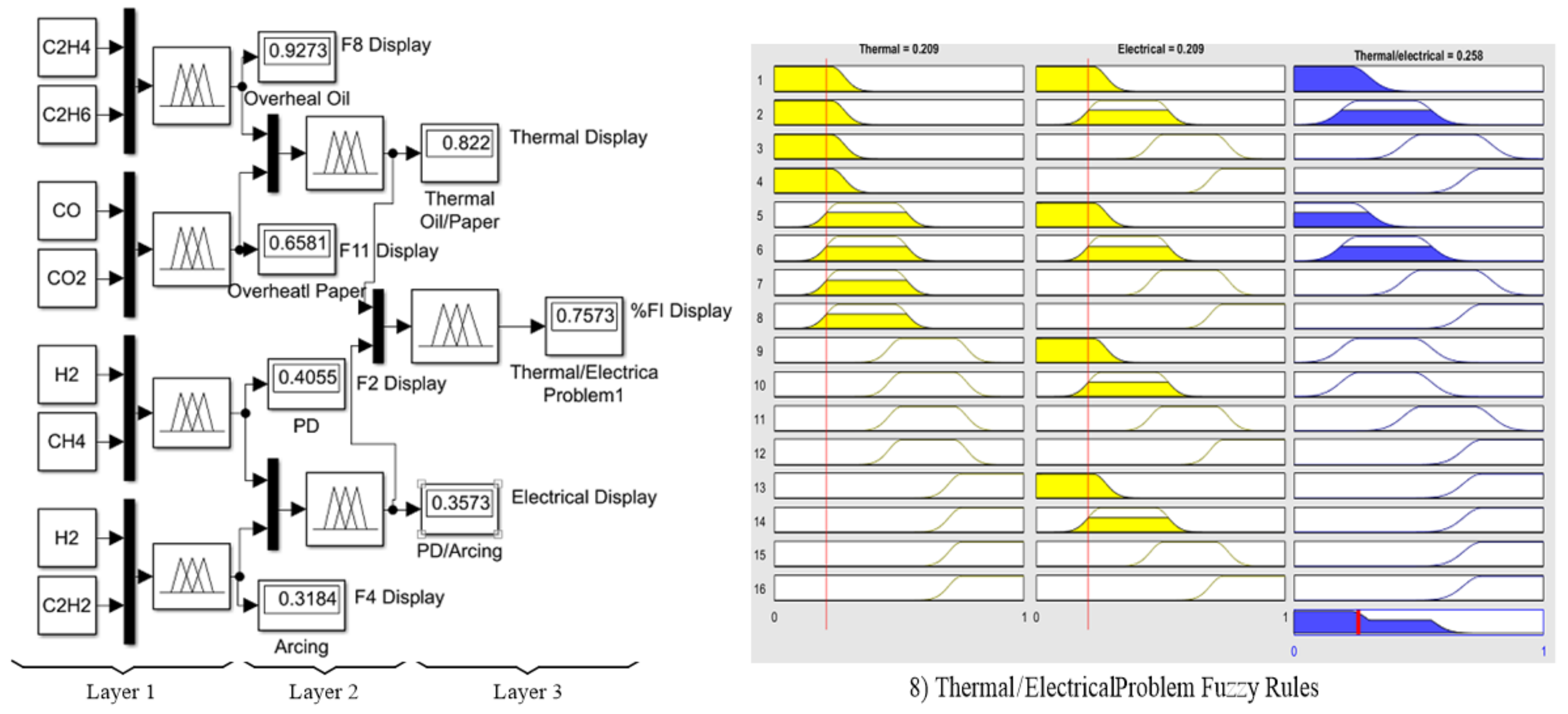
9]. The advantage of this method can be explained by the fact that there are overlapping areas, which are applied to identify the percentage of failure index (%FI). The 3-layer fuzzy logic model with 16 fuzzy rules was proposed and expressed in
Figure 2 (left), while the shapes of the 16 fuzzy rules are shown in
Figure 2 (right). To obtain a precise result, the input ranges of seven input gases were identified according to
Table 2, while four output ranges of the output function were identified in
Table 5. The Fuzzy output codes and faults are then determined as written in
Table 6. Finally, the proposed defuzzification with COG method in Equation (5) was applied to calculate %FI, referring to the power transformer condition as written in
Table 7, which can be differentiated into three color bands as red, yellow, and green.
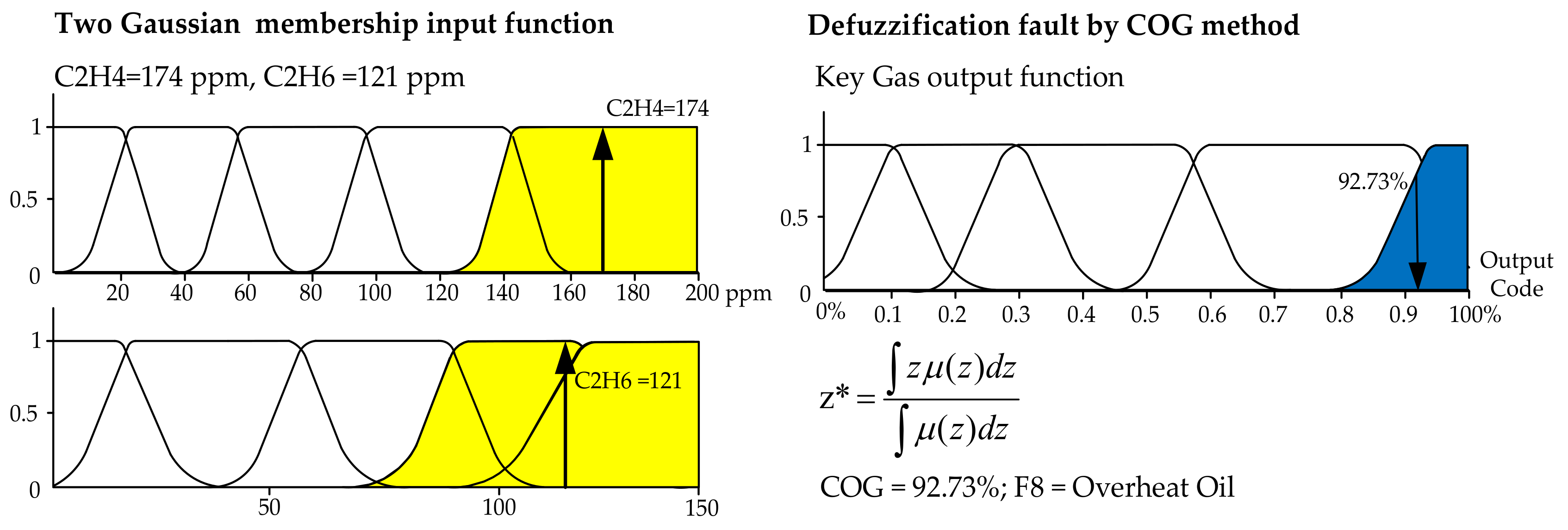
Figure 3 shows the two-Gaussian membership fuzzification and defuzzification procedure according to Equations (3) and (5), respectively. In
Figure 3 (left), for the first layer, two couples of key gases as CO and CO
2, C
2H
4 and C
2H
6, CH
4 and H
2, as well as C
2H
2 and H
2 as the inputs were compared to indicate %FI, while all four ranges of inputs are defined. In
Figure 3 (right), the types of faults in
Table 1 as outputs are defuzzified and decoded as F8 representing an overheating oil problem with 92.73% fault possibility. Similar to the 2nd layer, the couples F2 and F4 as well as F8 and F11 were further compared, resulting to the possibility of 82.2% as a thermal problem and 35.73% as an electrical problem. Finally, in the 3rd layer, %FI was then calculated as equal to 75.73%.
3.2. Application of the Fuzzy Logic Approach to IEC Ratio Method
In this paper, the triangular membership, as in Equation (3) and in
Figure 4, was applied to IEC ratio method [
13,
14,
15,
16] because of the explicit ranges of input conditions as low, medium, high, and very high resulting in easy interpretation. According to the model, ratios C
1, C
2, and C
3 in Equation (1) were first calculated. Then, the calculated result defined as “
” is the input of this membership function, as shown in
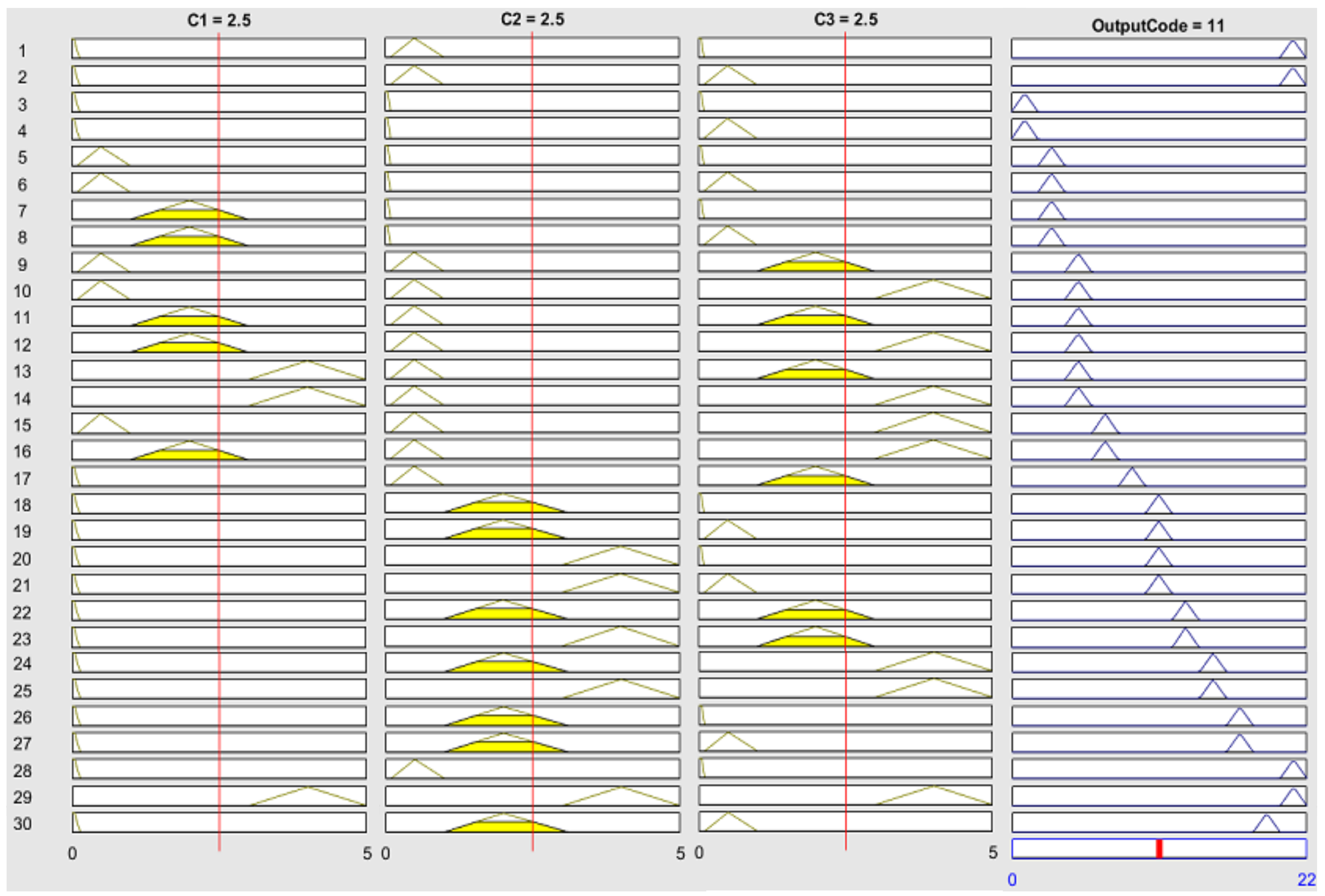
Table 8. A single-layer fuzzy model was then applied. Thirty fuzzy rules were proposed to identify possible faults, as shown in
Figure 4. The output code is represented by the numbers 1 to 21. Similarly, the defuzzification with the COG method is then applied. Nine faults are possible and written in the form of malfunction as given in
Table 9.
For the IEC Ratio method,
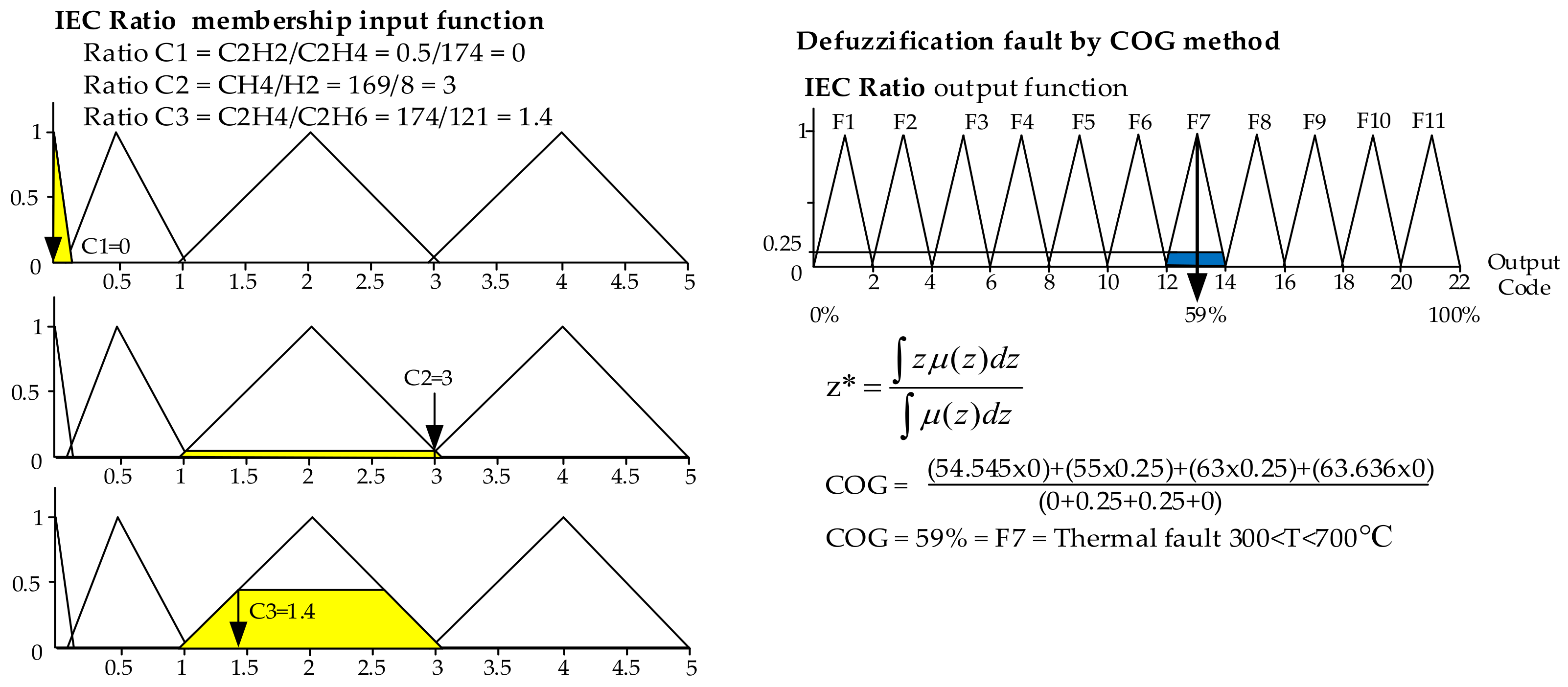
Figure 5 shows the first layer of triangle membership function fuzzification and defuzzification procedure according to Equations (3) and (5), respectively. In
Figure 5 (left), ratios C
1 = 0, C
2 = 3, and C
3 = 1.4 were calculated by using Equation (1) and represented as inputs in Equation (3). The four ranges of each input were defined, as shown in
Figure 5 (left). The types of faults as output are defuzzified as equal to 59% and decoded as F7 representing thermal fault problem (T2; 300 < T < 700 °C) as written in
Figure 5 (right).
3.3. Fuzzy Logic with Duval Triangle Method
The triangular membership function is applied to the Duval triangle method [
11,
12,
13,
14] because of the explicit ranges of the input with the most simple output code interpretation, as written in
Table 10. The percentages of ratio %CH
4, %C
2H
4, and %C
2H
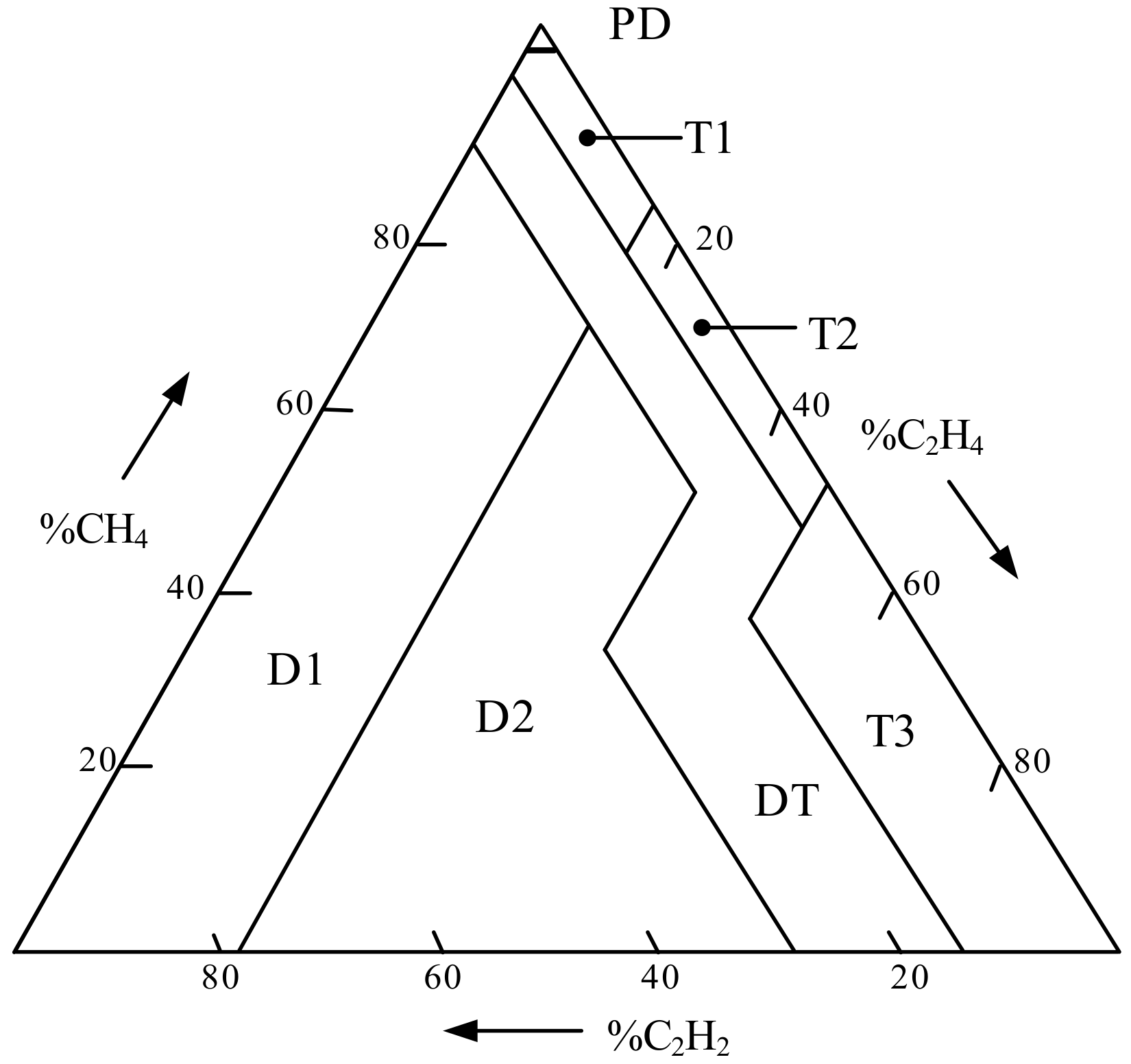
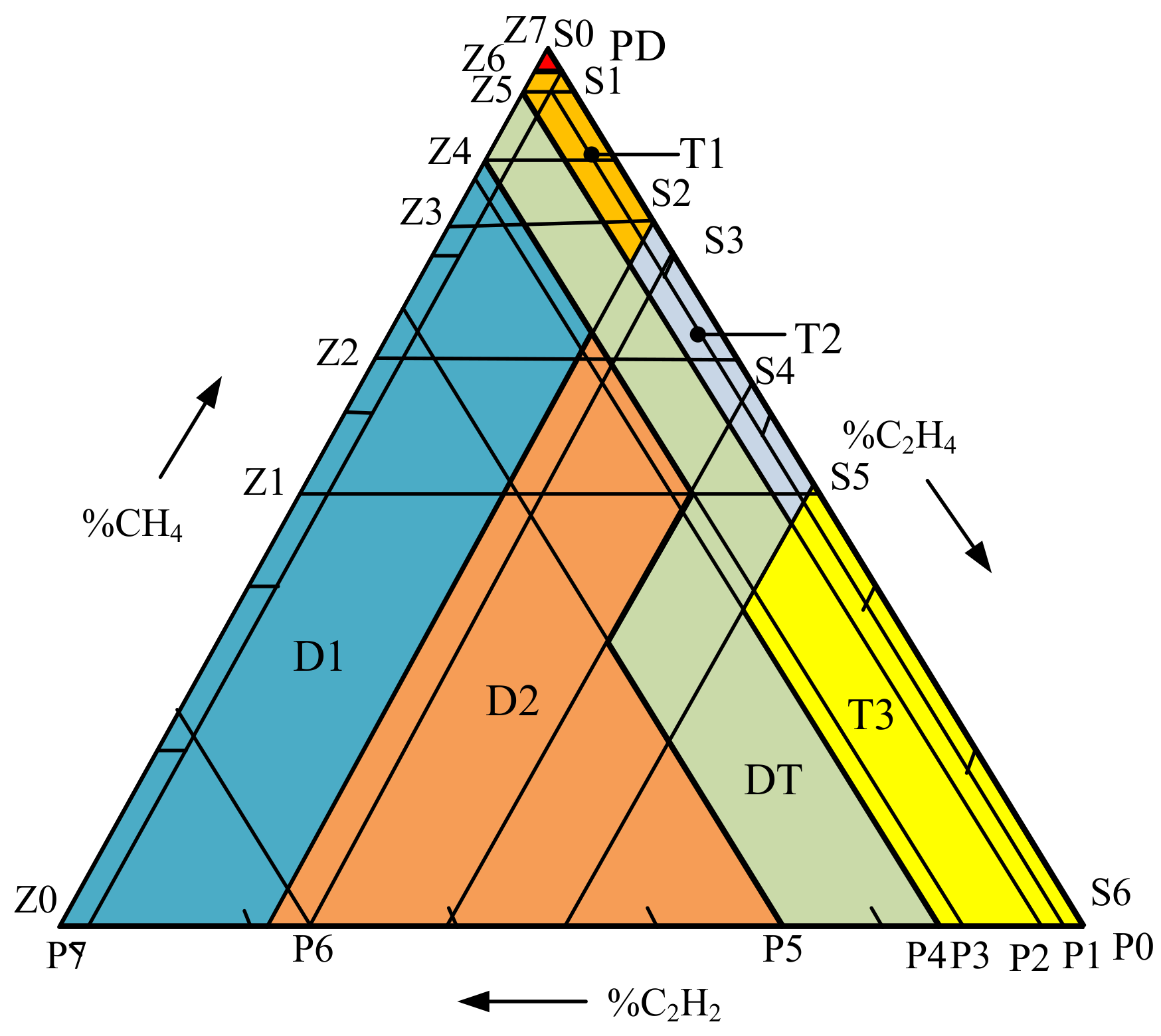
2 defined as Z, P, S parameters classified in different zones as written in Equation (6) are the inputs of the membership function for plotting in the Duval triangle as presented in
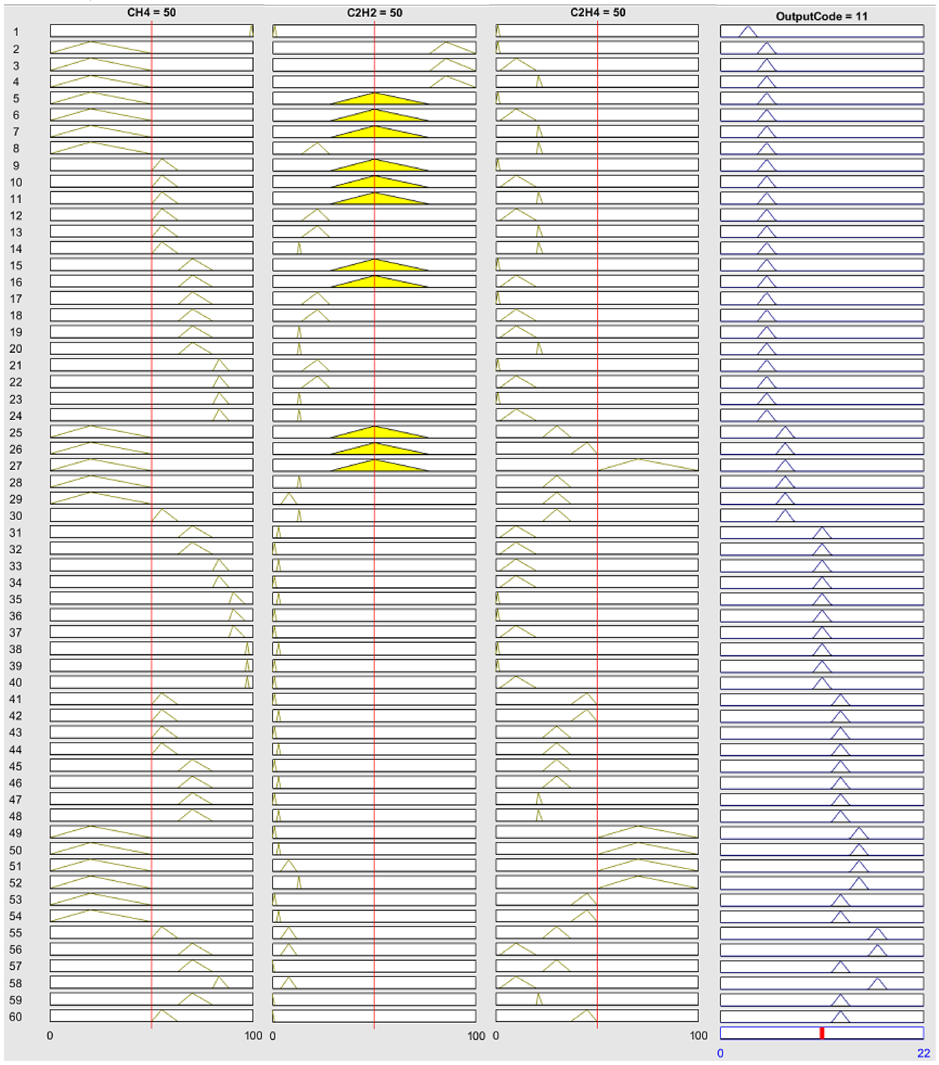
Figure 6. Similarly, a single-layer fuzzy model was applied. Sixty fuzzy rules were identified for possible faults, as shown in
Figure 7. Similarly, the output code was represented by numbers (1 to 21). The defuzzification with COG method was then applied. The eight fault types identified by the Duval triangle method are written in
Table 10.
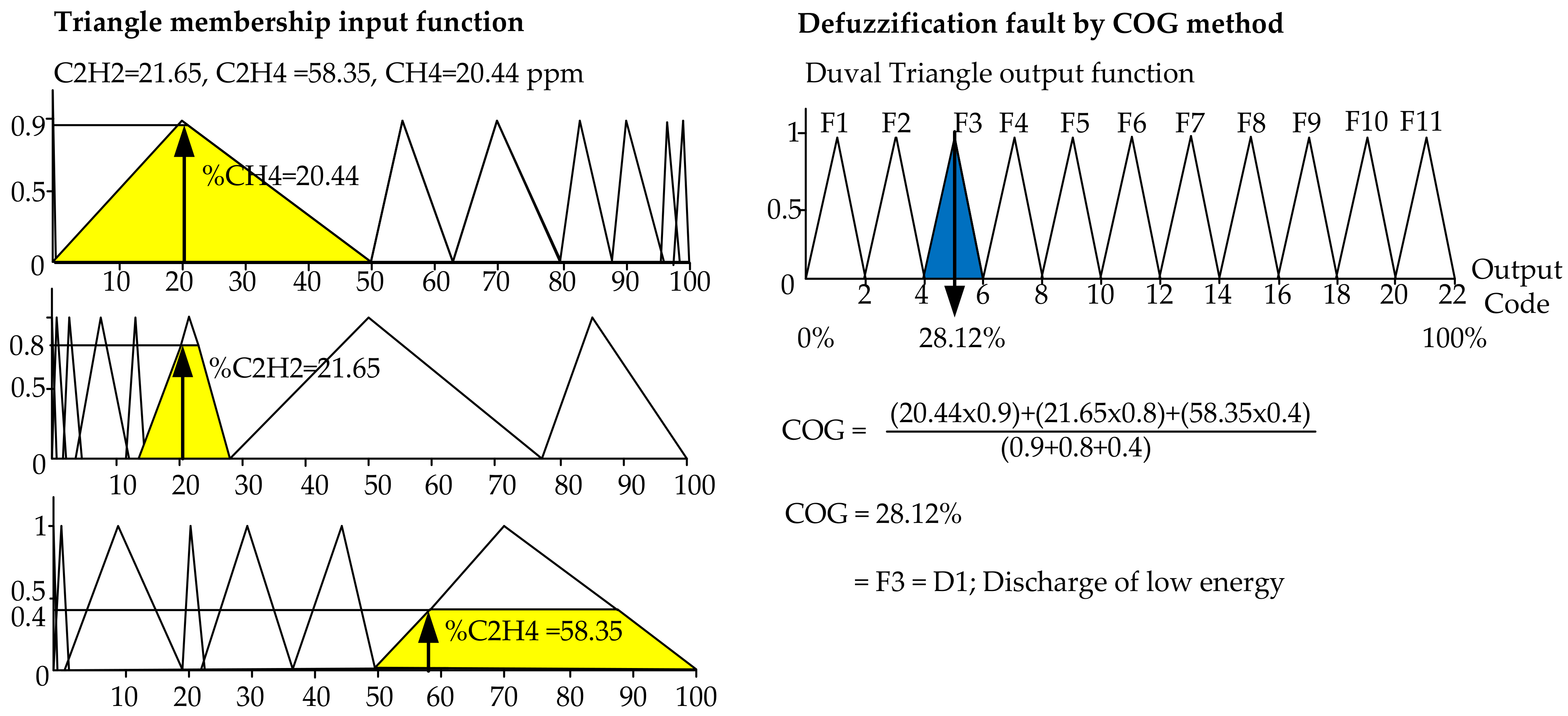
Figure 7 shows the fuzzy logic fuzzification and defuzzification procedure for the Duval triangle method by using Equations (3) and (5), respectively. The %CH
4, %C
2H
4, and %C
2H
2 were calculated as equal to 20.44, and 21.65, 58.35%, which are defined as Z, P, S parameters. The ranges of Z, P, S in Equation (6) are also drawn in
Figure 8 (left), while the COG was calculated by using fuzzy logic defuzzification and equal to 28.12% as shown in
Figure 8 (right), which falls into F3 decoded to D1 as the discharge of low energy.
3.4. Defuzzified Faults from Three Fuzzy Logic Methods
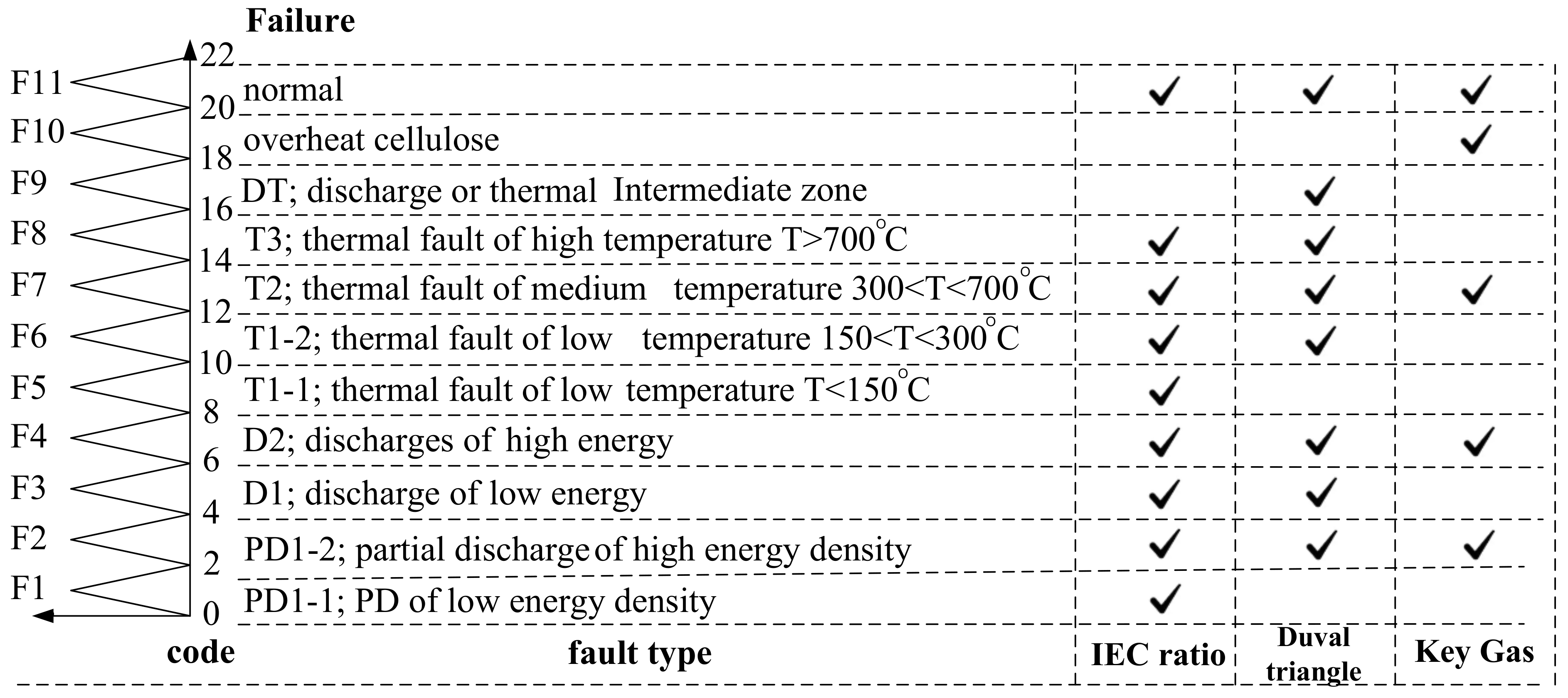
The proposed defuzzified codes from 1–21, representing eleven faults from three fuzzy logic methods and the key gas, IEC Ratio, and the Duval triangle method were compared, as shown in
Figure 9. For example, the defuzzified values between range 2–4 shows the faults as PD1-2 as the partial discharge of high energy density, exactly determined by all three methods. All methods should be simultaneously applied to precisely identify the failure inside the power transformer.
5. Conclusions
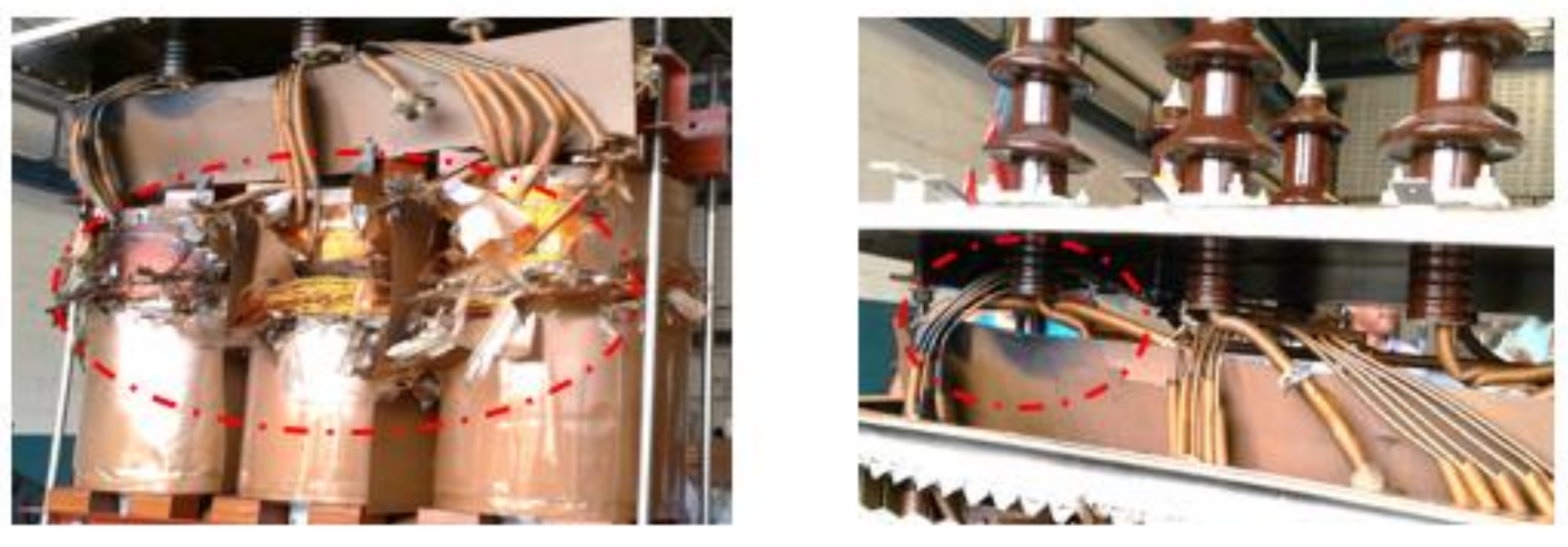
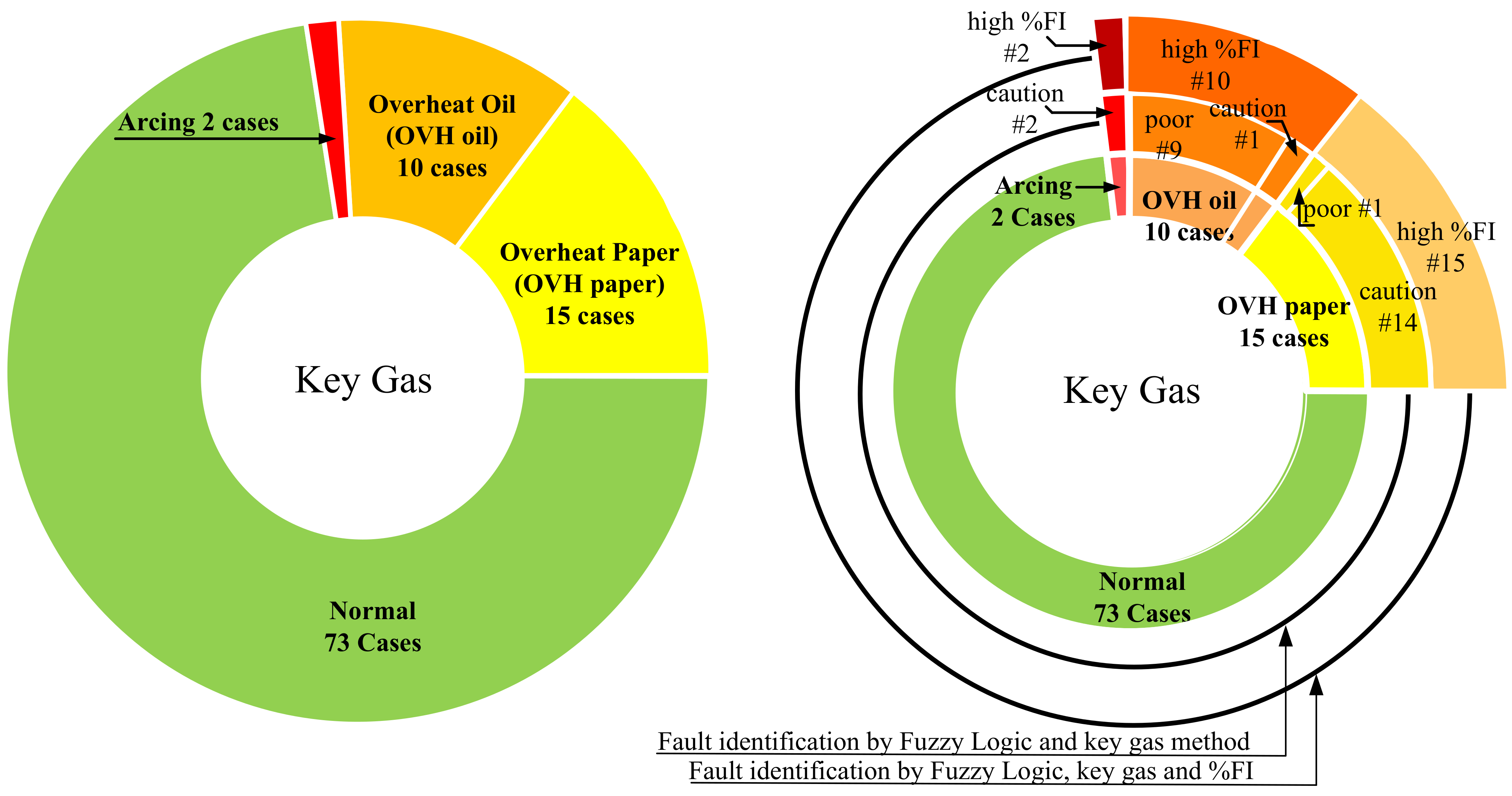
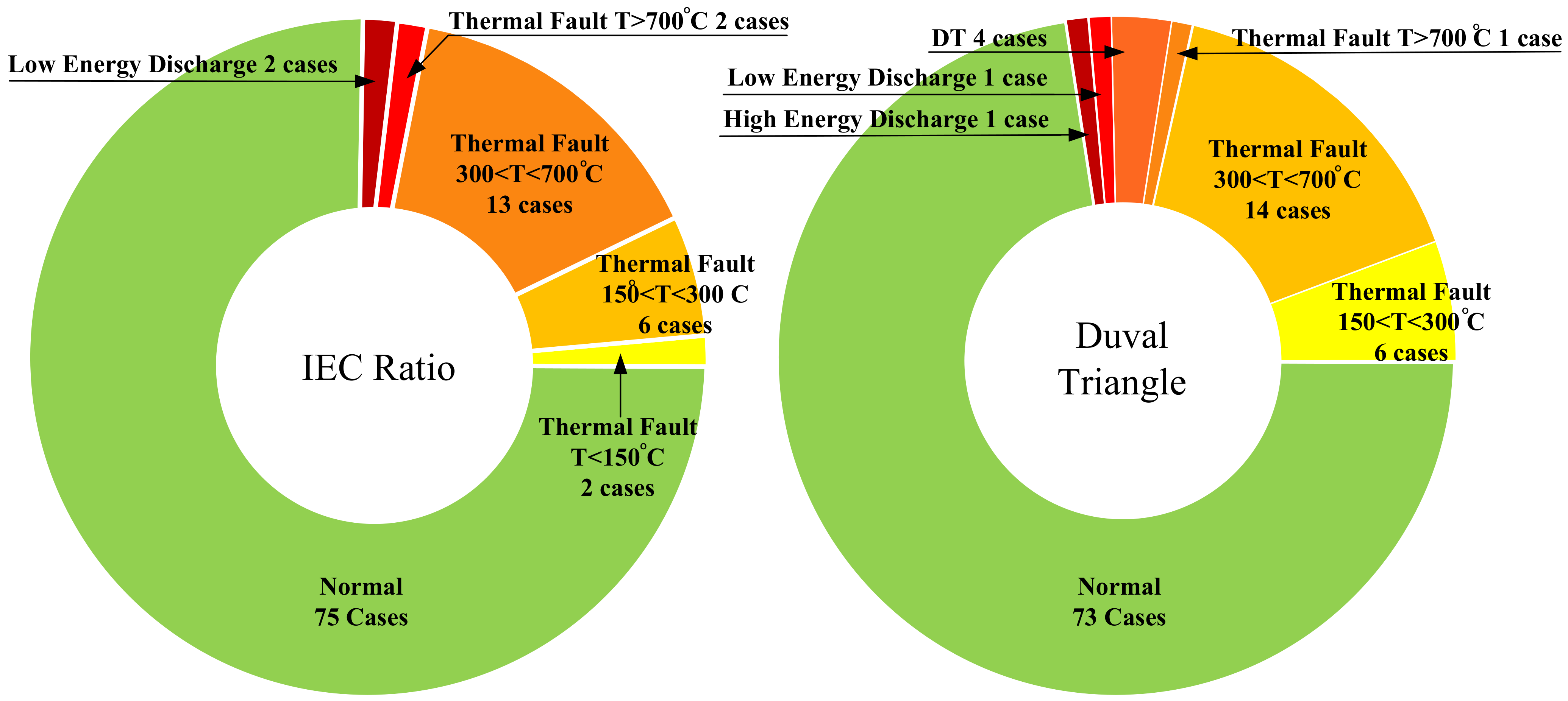
A fuzzy logic approach to three DGA methods; key gas method, IEC three-gas ratio and Duval triangle methods were used to evaluate the condition of power transformers by the percentage of the failure index and the internal fault determination. Moreover, the fuzzy logic with the key gas approach could calculate %FI and identify problems that may occur inside power transformers, while the IEC three-gas ratio and Duval triangle can confirm the problems in different failure types covering all possibilities inside power transformers. Then, the fuzzy logic applied to DGA results of two transformers were evaluated and practically confirmed by an un-tanked power transformer showing arcing at the core in both cases. In addition, the DGA results of ten transformers were further evaluated. The fuzzy logic approach with three DGA methods results were shown and compared. The condition and the internal problems of power transformers could be clearly identified. The graphic circle was introduced to compare the analyzed results of a large number of power transformers. Then, the severity of faults inside the transformers could be deeply identified in terms of the percentage of failure index. This fuzzy logic is a smart, accurate tool for automatically identifying faults occurring within transformers. Then, the recommended maintenance strategy and time interval were proposed for effective planning to minimize the catastrophic damage, which could occur with power transformers and their networks. Finally, the fuzzy logic simulation software with proposed techniques was developed as a low cost, easy, accurate, and less time-consuming tool.
