Article

The Short-Circuit Protections in Hybrid Systems with Low-Power Synchronous Generators

by
Bartosz Rozegnał
1,
Paweł Albrechtowicz
1,
Dominik Mamcarz
1,*,
Natalia Radwan-Pragłowska
1 and
Artur Cebula
2
1
Institute of Electromechanical Conversion, Cracow University of Technology, Warszawska 24 St., 31-155 Cracow, Poland
2
Department of Energy, Cracow University of Technology, Jana Pawła II Av., 31-864 Cracow, Poland
*
Author to whom correspondence should be addressed.
Energies 2021, 14(1), 160; https://doi.org/10.3390/en14010160
Submission received: 23 November 2020 / Revised: 23 December 2020 / Accepted: 28 December 2020 / Published: 30 December 2020
(This article belongs to the Special Issue Advanced Control Design and Fault Diagnosis)

Abstract

:
Single-phase short-circuits are most often faults in electrical systems. The analysis of this damage type is taken for backup power supply systems, from small power synchronous generators. For these hybrid installations, there is a need for standard protection devices, such as fuses or miniature circuit breaker (MCB) analysis. Experimental research mentioned that a typical protective apparatus in low-voltage installations, working correctly during supplying from the grid, does not guarantee fast off-switching, while short-circuits occur during supplication from the backup generator set. The analysis of single-phase short-circuits is executed both for current waveform character (including sub-transient and transient states) and the carried energy, to show the problems with the fuses and MCB usage, to protect circuits in installations fed in a hybrid way (from the grid and synchronous generator set).

1. Introduction

Most modern electrical installations are equipped with backup power systems. Electrical installations have to be protected against short-circuits, overloads, and electric shock, independently on the energy source, whether it is supplied from the grid or a local source, e.g., a diesel generator set [1,2].
All installations must be performed according to law requirements. In particular, proper protection must be ensured to allow for safe electrical installation usage (especially for non-educated users). Installations supplied from the grid have usually guaranteed the protection requirements, because standards on how the installation should be planned, and electrical protection equipment, should be selected [3]. International standards (Institute of Electrical and Electronics Engineers—IEEE, International Electrotechnical Commission—IEC) describe methods of short-circuit current calculations for three-phase fault cases [4,5]. For protection equipment selection during the designing stage, three-phase faults are assumed as the worst ones. However, steady-state single-phase faults appearing near the low-power generator are characterized by greater current values than three-phase faults [6].
Typically, as with short-circuit protection devices, there are used fuses and miniature circuit breakers (MCBs). These apparatuses have normalized values of rated currents and the tripping ones, so they should be selected for precisely defined cases in installations, to ensure fast and safe work in the installation fault cases, according to the standards (Table 1).
Additionally, in expanded building systems, there should be guaranteed protection devices working selectively [3]. This situation is different for installations supplied from the local low-power sources, especially in typical low-voltage installations supplied both from the power network and a local backup power source (called hybrid installations—Figure 1). In hybrid installations, while there is no voltage from the basic source (grid), the emergency power source is switched on (synchronous generator). This solution provides energy-independence, but also causes a need for detailed analysis of the short-circuit cases for backup mode. Problems can occur with achieving the same short-circuit conditions for the same protection device installed in given circuits, both for the supply from the grid and local backup generator. The described problem is shown in Figure 1.
The research about protections in installations supplied from low-power low-voltage synchronous generators are not widely described in literature [7,8,9]. In the available research, authors focus mainly on the issues related to circuit breaking as a result of protection releasing. In [7], expensive control systems supporting protection devices is presented, while the authors of [8] theoretically indicate the fuse efficiency. The research described in [9] concerns only the MCB device. All of these articles involve the individual protection of the generators.
A lot of information can be found in the literature about microgrid systems based on distributed local energy sources, such as photovoltaics (PV), wind generation, biogas plants, and challenges facing protection devices in transmission lines [10,11,12,13]. A certain range of short-circuit currents is common in microgrids, based on synchronous generators and hybrid installations, with backup power supply using synchronous generators, but the protection devices used in both cases are different (relatively high power microgrid systems usually use digital protection devices [13], where the application of those devices are economically justified. In low-voltage installations, which can be supplied from grid or local backup energy sources (hybrid installation), the circuits are usually protected by MCB and fuse devices (they are relatively cheap and reliable). The equipment used in transmission lines (as a part of microgrid systems) is very sophisticated compared to protections in buildings installations [14]. Therefore, in building installations, there is a need to investigate typically used protection apparatuses (during short-circuits in backup supply cases). It should be noted that, there is a possibility to properly protect the hybrid systems, cooperating with low-power generators; however, the costs of those protections are relatively high in comparison to generator prices [15].
In this article, we present laboratory tests of typical low-voltage electrical protections used widely in hybrid installations during backup working modes, using low-power synchronous generators in single-phase short-circuits cases. The research focused on fuses and MCB devices due to the previously mentioned advantages. The laboratory tests omitted the digital protection devices, which are not used widely in building installations because of their high prices in comparison to protected generator sets. The analysis of short-circuit current value changes and energy revealed during tested faults was performed to pay attention to protection needs in the assumed conditions of the hybrid installations. It should be noted that these protective apparatuses, chosen correctly to the protected circuits, work in appropriate ways, even with keeping the selectivity when the installation was supplied from the power grid. However, in this research, inefficient work was pointed out, for both MCBs and fuses, with different rated currents for the circuits supplied from the low-power synchronous generator as a backup energy source.

2. The Overcurrent Protection Devices

The most common overcurrent protection devices in the low-voltage installations are: fuses, miniature circuit breakers (MCB), selective circuit breakers (SCB), or motor circuit breakers. In case of fuses, the Joule’s integral was used to define effective work during failure. The Joule’s integral value has a significant impact on the switch-off time and is counted as a sum of two elements (total heat amount released before electric arc from t = 0 to t = t p and electric arc heat from t = t p to t = t o ) [7,9]:
I 2 t = 0 t p i k 2 d t + t p t o i k 2 d t
where:
  • t o —short-circuit switch-off time [s],
  • t p —time from short-circuit start to electric arc appearance [s],
  • i k —short-circuit current value [A].
Miniature circuit breakers are also often installed in the building switchgears and they switch off short-circuits fast enough when the current value during fault exceeds: 5 × MCB rated current for B characteristic, 10 × MCB rated current for C characteristic, 20 × MCB rated current for D characteristic [7,8]. There are many concepts of their technical realizations and functions [16,17,18].
Apart from conventional MCB with B, C, D characteristics, there is a group of selective circuit breakers (SCB). These protection devices have intentionally extended reaction time, to allow the short-circuit off-switching (by the closest to the place of the fault protection device, e.g., MCB). There can be characteristics E and F (6.25 × and 10 × SCB rated current, respectively) [19].
In electrical installations, a very important issue of the protective devices selection ensures proper working coordination of the protection apparatus to achieve selectivity. That requirement should be under consideration during installation planning, and possible alternative local energy sources (such as low-power synchronous generators) should be included in these calculations.
In the hybrid installation case (e.g., supplied from the main and local backup generator sets), there is a problem connected with providing an effective and reliable working protection apparatus (while short-circuits occur), and achieving selectivity in cooperation [9].

3. The Statistic of Short-Circuit Types and the Characteristic of Silent Poles Synchronous Generators

3.1. The Short-Circuit Types Participation

The most common short-circuit type in the electrical power systems are single-phase ones. Their participation in total faults are approximately 57.5% based on [19] or in 65% based on [20]. The rarest short-circuit types (from 0.5 to 5%) are three-phase or three-phase with earth short-circuits. Figure 2 shows statistics of short-circuits in detail. According to these data, in this article, analyses were taken of the typical low-voltage protective devices, in case of single-phase short-circuits.

3.2. The Characteristic of Low-Power Silent Poles Synchronous Generators

The low-voltage synchronous generators are widely used as a backup power supply in different types of buildings (from residential trough office, public to industrial objects). When the short-circuit phenomena occurs in the low-voltage system supplied by the backup generator set, this fault should be recognized by generator as a close. During this fault type, generator states can be highlighted: sub-transient, transient, and steady-state short-circuit as a consequence of phenomena that takes place inside the generator (electromagnetic flux path changes) [21,22]. Depending on the generator construction, short-circuit state values and their time intervals are different [23]. However, in a case of low-voltage units, electromagnetic time constants for sub-transient and transient states are very short, so the steady-state short-circuit is achieved very fast. Due to relatively high values of the generators synchronous reactance, the short-circuit current value during steady-state can be even smaller than its rated current (three-phase or three-phase to earth faults). In detail, this issue is described in [21], where the analysis was done.
As an example, parameter values of different synchronous generators are presented in Table 2 (the parameters are expressed in relative units and remain at a similar level).
Table 3 shows electromagnetic time constants for low-power synchronous generators used as a backup supply and for synchronous generators installed in the Polish National Power System.
In case of dependence on the short-circuit current of generators with salient poles, different values of direct and quadrature parameters of the generator should be taken into account [22,23,25,26]:
i k = U f m X d g 3 t c o s   ω t + γ 0 U f m 2 e t τ a   1 X d + 1 X q c o s   γ 0   1 X d 1 X q c o s   2 ω t + γ 0  
g 3 t = X d 1 X d 1 X d e t τ d + 1 X d 1 X d e t τ d + 1 X d
where:
  • U f m = 2   U f —maximum phase voltage value,
  • X d —direct axis synchronous reactance,
  • X d —direct axis transient reactance,
  • X d —direct axis sub-transient reactance,
  • X q —quadrature axis sub-transient reactance,
  • γ 0 —phase shift angle,
  • τ a —aperiodic time constant [s].
One important problem associated with the operation of low-power synchronous generators is the relatively small values of the sub-transient and transient electromagnetic time constants of these generators, generally defined as [22,23,25,26]:
τ d = L d R s
τ d = L d R s
where:
  • τ d —direct axis short-circuit transient time constant [s],
  • τ d —direct axis short-circuit sub-transient time constant [s],
  • L d —direct axis transient inductance [H],
  • L d —direct axis sub-transient inductance [H],
  • R   —armature resistance [Ω].

4. The Laboratory System

4.1. Description of the Measurement System

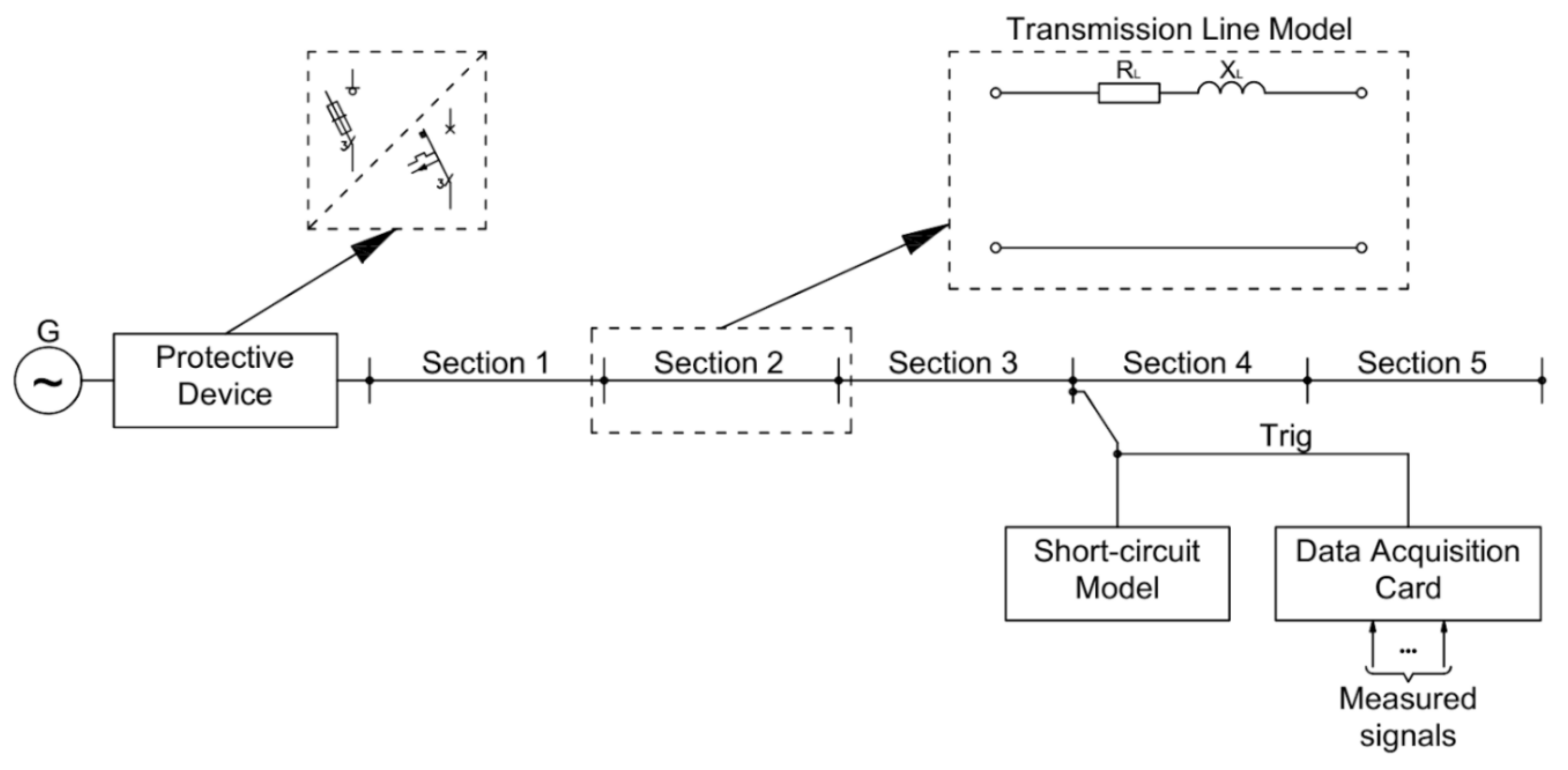
Short-circuit current analysis was carried out in a system powered by a synchronous generator with rated power equal 16 kVA (the rated data of the generator are presented in Table 1 and Table 2—marked column), driven by a DC motor MS1322 M32 (made by Leroy-Somer, Angouleme CEDEX, France)—shown in Figure 3a,b. The created laboratory power system model powered a static receiver of the RL type (adjustable resistance load from 0 kW to 9 kW, with the step of 0.6 kW, and inductance reactance from 0 kVAr to 9 kVAr) through a sectioned model of II type lines (parameters of each section were the same and equal to R S   =   0.22   , X S   =   0.04   ). Additionally, a specially prepared short-circuit module and measurement system with data acquisition were included in the model.
The constructed short-circuit module made it possible to set the short-circuit duration up to 2 s, while the maximum value of the short-circuit withstand current was up to 1600 A.
According to the appropriate design of the short-circuit module, it was possible to make various types of short-circuits—from single-phase to three-phase (with and without earth). The module was connected between the appropriate sections of the transmission line. This circuit was also the source of the external trigger signal.
The measurement system with data acquisition was created with the usage of the measurement card NI USB-6259 and NI LabView SignalExpress version 15.0.0 software (National Instruments Corp., Austin, TX, USA) and current clamps. The external triggering signal source for the data acquisition system was the signal from the short-circuit module (the measurement system could be switched on before the short-circuit occurred in the range from 50 ms up to 500 ms) [27]. The sampling frequency was set to 100 kHz.
Short-circuit current signals were measured with the usage of current clamps FLUKE ac i1000s (measurement range 100 A (10 mV/A, accuracy 2% of reading ±5 mV) and 1000 A (1 mV/A, accuracy 1% of reading ±1 mV)) with bandwidth range from 5 Hz to 100 kHz.
To verify the low-voltage protection apparatus used in the installations supplied from the alternative energy sources, such as low-power synchronous generators, short-circuit current research, appearing in the part of the low-voltage power system, was conducted. The scheme of the laboratory arrangement is presented in Figure 4.

4.2. Experimental Work

The electrical hybrid power system made in the laboratory scale tested MCB types B and C with rated currents: 16 A, 20 A, 25 A, and also the full range fuses gG type CH10 × 38 with rated currents 10 A, 16 A, 20 A, 25 A. All types of mentioned protections were tested for different current values. Due to the possibility of short-circuit occurrence place change in the five section line model (second type), there was the possibility of getting different short-circuit impedance loop values, and, thereby, modeling different short-circuit conditions. The tested apparatuses were installed on the output nodes of the synchronous generator (Figure 4).
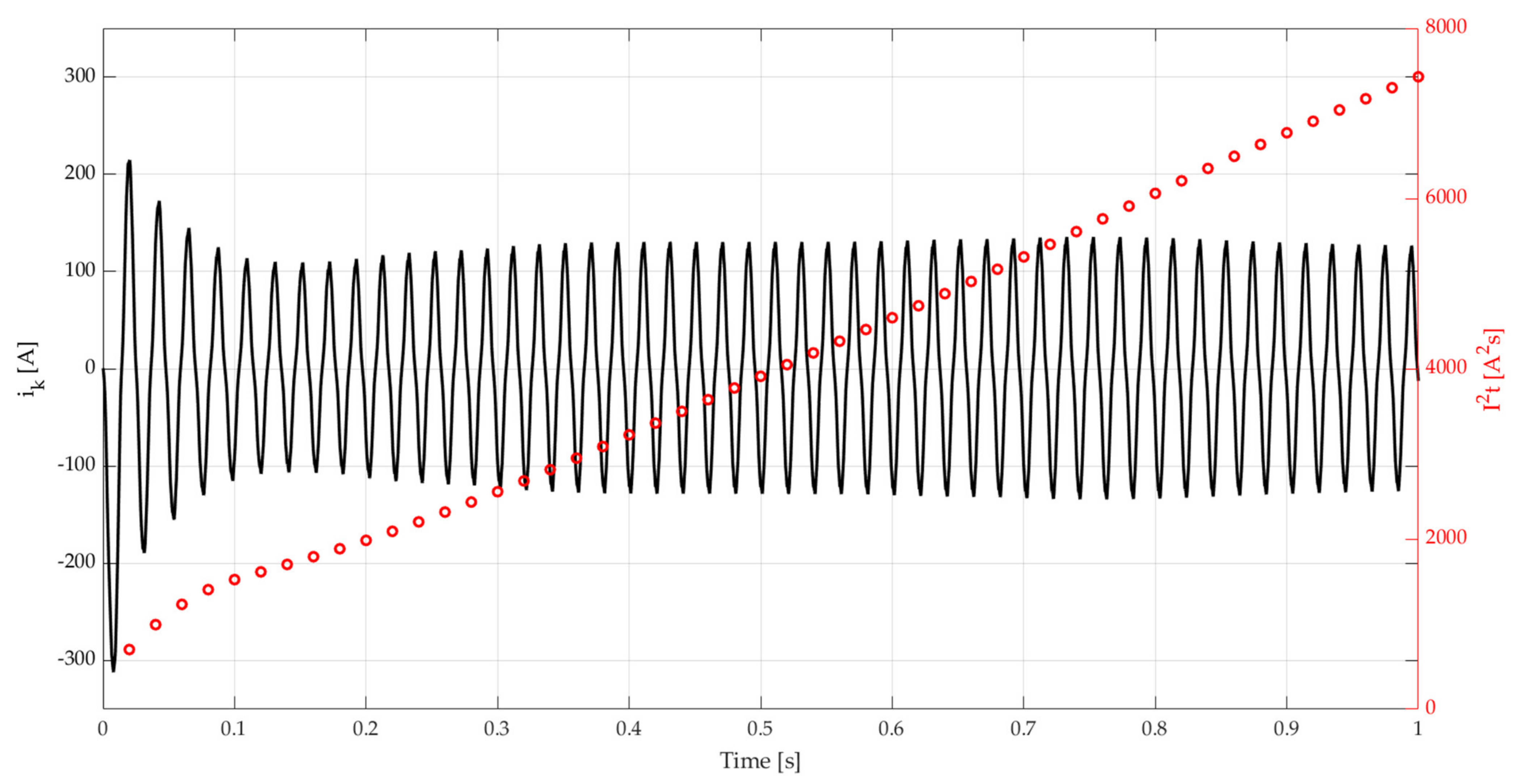
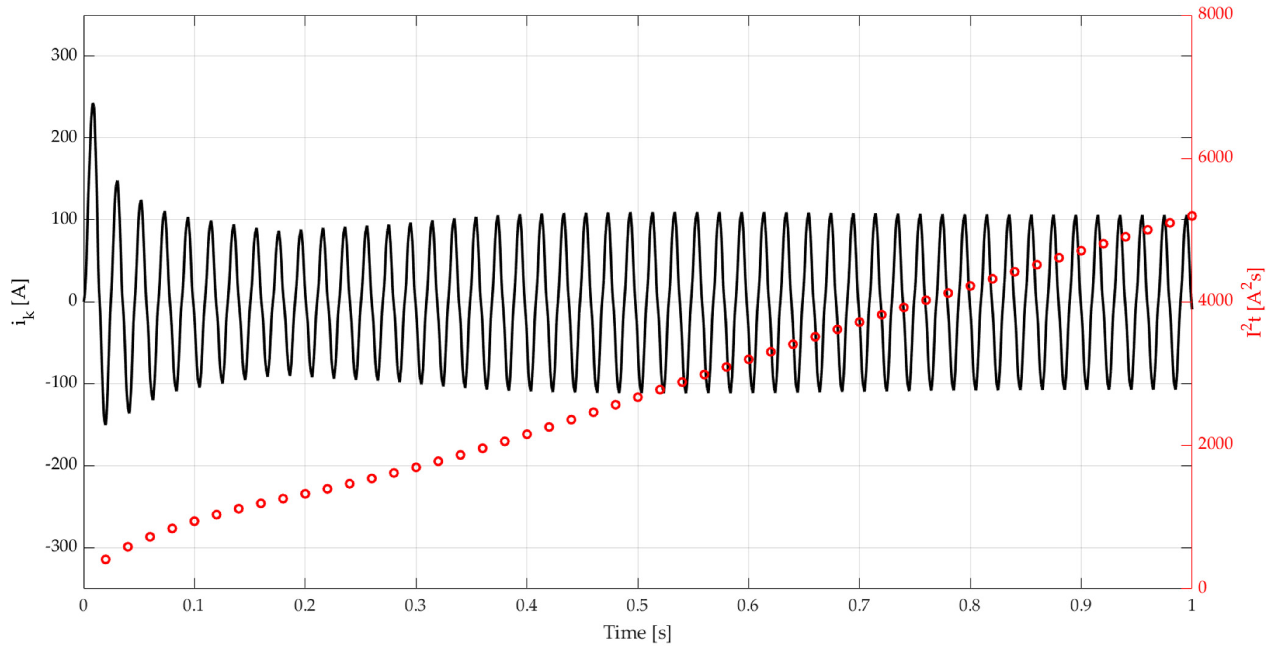
All tests were performed for the single-phase short-circuit set time equal 1 s. Figure 5 and Figure 6 present short-circuit current waveforms for chosen fault places, after the first and third sections counted from the generator G nodes.
Additionally, by means of the red markers, there are visualized changes of the revealed heat energy during short-circuit (Joule’s integral calculated after each period) on the metal strip of the fuse during current flow [28].
Figure 5 shows that sub-transient and transient states during short-circuit have significant impact on the total Joule’s integral value due to it being on the installed protection apparatus. The line distance to the fault is longer (so the line impedance is bigger), the transient phenomena influence on the short-circuit current shape and value is smaller. Therefore, in case of short-circuit after the third section (Figure 6), the Joule’s integrals grow almost in a linear way. This effect should be especially taken into account during protection selection to achieve reliable work.
An impact of the line length (and so longitude impedance) on the steady-state short-circuit current should be noted. The analyzed single-phase short-circuit maximal and steady-state current values (during fault) are presented in Table 4. In each case, the line resistance RS to the line reactance XS ratio was equal to 6. In the presented approach, the authors showed that, on the released energy and in consequence to the short-circuit switching-off time, beside the steady-state short-circuit current value, the significant influence has transient and sub-transient states (depending on the longitude line impedance), generator type, and generator excitation type. It should be noted that in hybrid installation cooperating with backup power sources, the short-circuit is always consider as close. In those type faults, the released energy, during transient and sub-transient, is significant compared to the overall short-circuit energy. For the fault after the first line section, the energy released during the first five periods of the short-circuit (unsteady state) is equal to 1750   A 2 s , while during the steady-state for the same time period, this energy is 550   A 2 s . Thus, the described situation is important for the protective apparatus reaction times.
In the single-phase short-circuit, the line impedance growth causes steady-state short-circuit current decrease. Comparing this fact with the research [20], this dependence during protection selection, including the load type (three-phase or single-phase load), and expected current values (for symmetrical faults for the different line lengths the steady-state short-circuit current values were almost the same), should be taken into account.
Analyzing results presented in Table 5 and the Joule’s integral as time function (Figure 7) created for the tested fuses, it can be seen that single-phase off-switching is possible, but in time, which is longer than required by the standards [3]. In turn, for MCB, the most important impact on the short-circuit off-switching has, first, sub-transient states, when the current magnitudes are much bigger than for steady-state short-circuit. Each case of the MCB proper work occurs in half-periods (10 ms) for short-circuit currents, which values precisely depend on the electromagnetic flux displacing from the generator’s rotor. When there is no MCB electromagnetic part reaction during the surge current flow, there is the possibility to switch-off the short-circuit by the MCB overcurrent element. However, off-switching time is much bigger than required to anti-electric shock protection.
The fuses usage in hybrid installations show inefficiency in fast reactions on short-circuits supplied from low-power low-voltage synchronous generators. For analyzed cases, the generator rated current is 23.1 A, so, according to the design guidelines, there can be a selected protection apparatus with a nominal current greater than it (i.e., 25 A) for supplying high power loads. Moreover, because of that situation, it is visible that gG20A and 25 A fuses never ensure required protection levels in presented conditions during the backup supply mode.
The literature presents fuse characteristics I 2 t versus expected short-circuit currents I k . However, close to the generator faults, such as in this work, there appears sub-transient and transient phenomena, and after, a constant current value in steady-state short-circuit. Thus, there is a problem with choosing the equivalent short-circuit current value to verify switching-off times. A certain solution could be taking the steady-state short-circuit current as the least advantageous condition for the fuse. Then, counting the sub-transient and transient periods, should achieve a faster reaction than assessed on the I 2 t versus I k characteristic for the assumed steady-state short-circuit value. Research data, presented in Table 4, show that the most commonly used protective devices (with typically rated currents) do not guarantee fast circuit breaking in case of supplication from the low-power generator set. Additionally, it is worth noting that, very often, the generator’s manufacturer instructs to protect its device by MCB with a type and current rated that, even in case of a short-circuit fault on the generator terminals, does not guarantee the appropriate protection. For example, the diesel generator manufacturers use MCB C16A as protection from overload and short-circuit in a three-phase generator with power rating 7.7 kVA [29].
According to data contained in Table 4, obtained during a laboratory test, in Figure 7, it is visible is that the gG25A fuse will never switch-off the short-circuit. The gG20A fuse would probably be burned out in time (much longer than 1 s). The gG16A and gG10A fuses switched-off the short-circuit in 10 ms, what is confirmed on the chart (for gG16A, there are two cross points: first in 10 ms, second in 520 ms). The whole curve gG10A is below the line of the real measured energy (black dot line), so that the fuse worked immediately. The Joule’s integrals in Figure 7 were obtained based on the catalogue data [30]. The calculated curves of Joule’s integrals regard the changes of short-circuit current flowing times. Based on the presented characteristics (Figure 7), there is the possibility to verify the burning out times for different fuses. Additionally, the derivative of fuse characteristic allows to evaluate the chance of circuit breaking, in case of higher fuse rated currents for longer short-circuit times (for example based on the mentioned method, the gG20A fuse can be burned out, approximately, after 2.2 s).

5. Conclusions

The analysis of the single-phase short-circuit current pointed out the character of current changes during faults close to the generator. For small supplying units, sub-transient and transient states are short due to small electromagnetic time constants. This issue directly impacts the switching-off operation possibility by MCB electromagnetic element (the current values decreases rapidly) resulting only in releasing the protective apparatus by the revealed heat (bimetallic element in MCBs or the wire in fuses).
Revealed heat for considered cases is presented as Joule’s integrals after each period. The energy increments are the biggest for the first moments after fault appearing (as a consequence of the sub-transient and transient phenomena). The energy counted for these several periods is up to three times greater than the energy of the same time period in the steady-state short-circuit. That current character is desired and allows for faster protective device reaction. Additionally, the presented laboratory research has shown that some typically used protection apparatuses in the electrical installations do not fully—or even at all—realize requirements concerning electric shock prevention in case of synchronous generators as backup supply
As a consequence of ineffective installation protection, for some MCB or fuses there is no possibility of protection devices working selectivity; in developed installations, it can be a real problem with adjoining circuit functioning, where there are no short-circuits.
Ineffective working, or even no reaction of protection devices in the installations supplied from the backup supply, may lead to permanent damage of electrical wires and cables, if the short-circuit is not switched-off in the required time. That situation can also affect the generator and damage it, and in some extreme cases, start a fire. Cases of working protection devices in hybrid installations show real problems and there is a need for more awareness for both synchronous generator and apparatus (MCB, fuses) selection.
The summary of the measured energy values released for a short-circuit current for different line impedance values, with experimentally determined Joule’s integral values, will allow preparation of an optimal protective device selection algorithm for hybrid electrical installation.

Author Contributions

Conceptualization, D.M., P.A., and B.R.; methodology, D.M., P.A., and B.R.; software, N.R.-P. and B.R.; formal analysis, B.R. and A.C.; investigation, D.M., P.A., and B.R.; resources, D.M., P.A., B.R., N.R.-P., and A.C.; data curation, D.M. and P.A.; writing—original draft preparation, P.A. and N.R.-P.; writing—review and editing, D.M. and P.A. All authors have read and agreed to the published version of the manuscript.

Funding

This research was funded by the Polish Ministry of Science and Higher Education and performed by the Institute of Electromechanical Energy Conversion and Department of Energy of Cracow University of Technology.

Data Availability Statement

The data presented in this study are available on request from the corresponding author.

Conflicts of Interest

The authors declare no conflict of interest.

References

  1. Drozdowski, P.; Warzecha, A. Mathematical Study and Control of Diesel Rotary Uninterruptible Power Supply. In Proceedings of the 2019 15th Selected Issues of Electrical Engineering and Electronics (WZEE), Zakopane, Poland, 8–10 December 2019; pp. 469–475. [Google Scholar] [CrossRef]
  2. Best, R.J.; Morrow, D.J.; McGowan, D.J.; Crossley, P.A. Synchronous islanded operation of a diesel generator. IEEE Trans. Power Syst. 2007, 22, 2170–2176. [Google Scholar] [CrossRef]
  3. Regulation of the Minister for Infrastructure and Construction Amending the Regulation of the Minister for Infrastructure of 12 April 2002 on the Technical Conditions to Be Met by Buildings and Their Location, Dz.U. 2002 nr 75 poz. 690. Available online: http://isap.sejm.gov.pl/isap.nsf/download.xsp/WDU20020750690/O/D20020690.pdf (accessed on 15 June 2002).
  4. IEEE Std 30045-2014. Recommended Practice for the Application of Low-Voltage Circuit Breakers in Industrial and Commercial Power Systems; IEEE: New York, NY, USA, 21 August 2014. [Google Scholar]
  5. IEC 60909-0:2016. Short-Circuit Currents in Three-Phase a.c. Systems–Part 0: Calculation of Currents, 28 January 2016.
  6. Wiatr, J. Generating Sets in Emergency Power Supply Systems for Buildings. In Notebooks for Electricians–no 3 Series; Publishing House Medium: Warsaw, Poland, 2009. [Google Scholar]
  7. Ludwinek, K.; Szczepanik, J.; Sułowicz, M. Experimental analysis of assessing of the tripping effectiveness of miniature circuit breakers in an electrical installation fed from a synchronous generator set. Electr. Power Syst. Res. 2017, 142, 341–350. [Google Scholar] [CrossRef]
  8. Kozmian, R.; Kusz, A.; Kuna-Broniowski, M.; Makarski, P.; Scibisz, M.; Ludwinek, K.; Nadolski, R.; Staszak, J. Assessing of the Tripping Effectiveness of Fuses in Electrical Installation Fed from a Synchronous Generator Set. In Proceedings of the 2015 Selected Problems of Electrical Engineering and Electronics (WZEE), Kielce, Poland, 17–19 September 2015; pp. 1–4. [Google Scholar] [CrossRef]
  9. Albrechtowicz, P.; Szczepanik, J. The analysis of the effectiveness of standard protection devices in supply systems fed from synchronous generator sets. In Proceedings of the 2018 International Symposium on Electrical Machines (SME): SME 2018, Andrychów, Poland, 10–13 June 2018; pp. 1–5. [Google Scholar] [CrossRef]
  10. Gautam, V.P.; Joseph, F.C. Evaluation of Short Circuit Currents in Networks with Low Voltage Ride Through (LVRT) Enabled Voltage Source Converters (VSC) based Wind Turbines. In Proceedings of the 2018 20th National Power Systems Conference (NPSC), Tiruchirappalli, India, 14–16 December 2018; pp. 1–6. [Google Scholar] [CrossRef]
  11. Gopalan, S.; Sreeram, V.; Iu, H.; Mishra, Y. An Improved Protection Strategy for Microgrids. In Proceedings of the IEEE PES ISGT Europe 2013, Lyngby, Denmark, 6–9 October 2013; pp. 1–5. [Google Scholar] [CrossRef]
  12. Sahoo, A.K. Protection of microgrid through coordinated directional over-current relays. In Proceedings of the 2014 IEEE Global Humanitarian Technology Conference–South Asia Satellite (GHTC-SAS), Trivandrum, India, 26–27 September 2014; pp. 129–134. [Google Scholar] [CrossRef]
  13. Sahebkar Farkhani, J.; Zareein, M.; Najafi, A.; Melicio, R.; Rodrigues, E.M.G. The power system and microgrid protection—A Review. Appl. Sci. 2020, 10, 8271. [Google Scholar] [CrossRef]
  14. Rozegnał, B.; Albrechtowicz, P.; Mamcarz, D. The protections of the 5-node medium voltage power system in case of the symmetrical faults. In Proceedings of the 2019 15th Selected Issues of Electrical Engineering and Electronics, WZEE 2019, Zakopane, Poland, 8–10 December 2019. [Google Scholar] [CrossRef]
  15. Gordon, P. Developments from the R&D Community: Control and Protection of Diesel Gen-Sets; The Institution of Electrical Engineers: Savoy Place, London, UK, 1998; pp. 6/1–6/5. [Google Scholar]
  16. Meng, Q.; Li, S.; Jiao, Z. A Cut-off protection circuit based on dynamic arc recognition and termination technology. Electr. Eng. 2019, 20, 23–27. [Google Scholar]
  17. Gong, H.; Zong, M. Study on the new structure and its influencing factors of miniature circuit breaker for short circuit protection. In Seventh International Conference on Electronics and Information Engineering; IEEE: New York, NY, USA, 2017. [Google Scholar] [CrossRef]
  18. Chen, L.; Chen, Y.; Ding, Q. Selective Switch with Selective Protective Module. Patent Number CN1617405A, 3 December 2004. [Google Scholar]
  19. Popczyk, J. Present and Expected Short-Circuit Current Values in Electrical Power Systems; Energetyka: Warsaw, Poland, 1986; pp. 6–10. (In Polish) [Google Scholar]
  20. Kanicki, A. The Symmetrical Component Method Used to Modeling Transient States of Electrical Power System; Tom Z349; Wydawnictwo Politechniki Łódzkiej: Wólczańska, Poland, 2006; pp. 3–176. [Google Scholar]
  21. Mamcarz, D.; Albrechtowicz, P.; Radwan-Pragłowska, N.; Rozegnał, B. The Analysis of the Symmetrical Short-Circuit Currents in Backup Power Supply Systems with Low-Power Synchronous Generators. Energies 2020, 13, 4474. [Google Scholar] [CrossRef]
  22. Latek, W. The Theory of Electrical Machines; WNT: Warszawa, Poland, 1987. (In Polish) [Google Scholar]
  23. Kacejko, P.; Machowski, J. Short Circuits in the Electroenergetic System; WNT: Warszawa, Poland, 2020. (In Polish) [Google Scholar]
  24. Linz Electric Generators. Available online: https://www.linzelectric.com/index.cfm/en/products/ (accessed on 6 July 2020).
  25. Das, J.C. Short-Circuits in AC and DC Systems: ANSI, IEEE and IEC Standards; Taylor & Francis Inc.: Portland, OR, USA, 2017. [Google Scholar]
  26. Chiver, O.; Neamt, L.; Matei, O. Comparative study on sudden short-circuit currents of a synchronous generator. In Proceedings of the 2015 IEEE 15th International Conference on Environment and Electrical Engineering (EEEIC), Rome, Italy, 10–13 June 2015; pp. 1688–1693. [Google Scholar] [CrossRef]
  27. Ludwinek, K. Measurement of Momentary Currents by Hall Linear Sensor. Prz. Elektrotech. 2009, 85, 182–187. [Google Scholar]
  28. Ocłoń, P.; Pobędza, J.; Walczak, P.; Cisek, P.; Vallati, A. Experimental Validation of a Heat Transfer Model in Underground Power Cable Systems. Energies 2020, 13, 1747. [Google Scholar] [CrossRef] [Green Version]
  29. Proton Polska–Commercial Offer. Available online: https://proton-polska.pl/product-pol-497-Agregat-pradotworczy-Proton-Oasis-3.html (accessed on 20 November 2020).
  30. ETI Fuses Catalogue. Available online: https://www.etigroup.eu/images/userfiles/en-GB/documents/products/building_industry/BIE_digital_2019.pdf (accessed on 21 September 2020).
Figure 1. Distribution Box (DB) circuit diagram.
Energies 14 00160 g001
Figure 2. The short-circuit type participation in power supply system—data from [19].
Energies 14 00160 g002
Figure 3. The outside (a) and inside (b) view on the short-circuit module.
Energies 14 00160 g003
Figure 4. The laboratory system used to tests of the protective devices.
Energies 14 00160 g004
Figure 5. Waveforms of the short-circuit current and the revealed heat energy during short-circuit for L 1 phase (first phase of generator) for a single-phase short-circuit case after the first line section.
Energies 14 00160 g005
Figure 6. Waveforms of the short-circuit current and the revealed heat energy during short-circuit for L 1 phase (first phase of generator) for a single-phase short-circuit case after the third line section.
Energies 14 00160 g006
Figure 7. The fuses Joule’s integrals and real measured energy comparison for fault after first line section.
Energies 14 00160 g007
Table 1. The maximal permissible off-switching times—requirements according to [3].
Rated phase voltage, U o [V] 50 U o 120 120 U o 230 230 U o 400
Maximal permissible off-switching time, t [s]0.80.40.2
Table 2. Two-pole synchronous generator data with a rated voltage of 400 V from Linz Electric company [24].
S n [kVA]1111.513.5162227
Number of poles222222
X d [%]280239275382373350
X d [%]211922262931
X d [%]5.84.65.3101211
X q [%]155130150166162152
Background color was used to pointed tested generator parameters.
Table 3. The values of electromagnetic time constants for the sub-transient and transient states [23,24].
S n [kVA]71013.5162227 2 × 10 5 6 × 10 5 15 × 10 5
τ d [ms]3333464147548308501210
τ d [ms]5.565.9667232830
Background color was used to pointed tested generator parameters.
Table 4. The measured currents and Joule’s integral for different short-circuit places.
The Number of Section I p e a k
A
I s s
A
I 2 t 1 s
A 2 s
Generator3401247913
First section3121297431
Second section2571156116
Third section2411055196
Fourth section214984497
Fifth section200934283
I p e a k —short-circuit current value in peak, I s s —steady-state short-circuit current value in peak.
Table 5. The off-switching times for different fault places and protective device types.
The Place of
Short-Circuit
Generator
[ms]
1st Section
[ms]
2nd Section
[ms]
3rd Section
[ms]
4th Section
[ms]
5th Section
[ms]
The Protective
Device Type
gG10A1010101010340
gG16A1010100650D.N.R.D.N.R.
gG20AD.N.R.D.N.R.D.N.R.D.N.R.D.N.R.D.N.R.
gG25AD.N.R.D.N.R.D.N.R.D.N.R.D.N.R.D.N.R.
C16A101010101010
C20A10101010D.N.R.D.N.R.
C25AD.N.R.D.N.R.D.N.R.D.N.R.D.N.R.D.N.R.
B16A101010101010
B20A101010101010
B25A101010101010
D.N.R.—The protection device does not release.
Publisher’s Note: MDPI stays neutral with regard to jurisdictional claims in published maps and institutional affiliations.