Article

Design of a Low Torque Ripple Three-Phase SRM for Automotive Shift-by-Wire Actuator

Department of Mechatronics Engineering, Kyungsung University, Busan 48434, Korea
*
Author to whom correspondence should be addressed.
Energies 2020, 13(9), 2329; https://doi.org/10.3390/en13092329
Submission received: 6 April 2020 / Revised: 23 April 2020 / Accepted: 28 April 2020 / Published: 7 May 2020
(This article belongs to the Special Issue Electric Systems for Transportation)

Abstract

:
The shift-by-wire (SBW) system in vehicles aims to increase performance, safety, and comfort during driving. Switched reluctance motors (SRMs) are simple, resilient, and require only minimum maintenance; these factors make it a good option for use as an SBW actuator. Inherently, SRM generates a higher torque ripple than other AC machines, which can lead to a deterioration of its function. In this paper, a non-uniform air-gap rotor structure combined with the careful positioning of holes near the pole surface is proposed to reduce the torque ripple. The finite element method (FEM) is employed to analyze the electromagnetic characteristics of the design. The proposed motor is manufactured, and experiments are done to verify the performance. The design alone can reduce the torque ripple by 7% and flatten the torque waveform. The experimental result shows that the proposed motor can achieve the desired performance. The estimated torque ripple from the experiment is 26.65%.

Graphical Abstract

1. Introduction

Automotive x-by-wire systems have undergone a significant technological development over the last few decades. The “x” refers to the function segment of a car, such as parking, shifting, and braking, and varies widely. In shift-by-wire (SBW), the traditional mechanical connection between the gearshift activator (e.g., shift lever) and transmission is replaced with electric components. There are four common shifting modes—parking (P), reverse (R), neutral (N), and driving (D)—which the driver can switch to easily. When a command is given, it activates the electronic control that rotates the actuator to change the gear. SBW systems are easier to assemble and require less space, so there will is more room for interior design. Moreover, it adds convenience and comfort in driving [1]. According to [2], the three most important aspects in designing and manufacturing vehicle transmissions are their long service life, low repair cost, and low production costs, each of which score 9.00, 4.89, and 4.59 out of 10 points, respectively. In other words, the robustness of the system is the most essential factor.
Switched reluctance motors (SRMs) satisfy the three top requirements. The structure is simple and resilient. The core is doubly-salient with no permanent magnets, and the windings are only wound on the stator in a concentrated way. Moreover, the end-coil length is short, and so the motor is relatively small and compact overall. In terms of its structure, SRM is highly robust. SRM has been reported to be used by Toyota and Lexus as the motor is reliable and highly responsive [3,4].
SRMs are singly-excited and inherently generate a high torque ripple compared to AC machines running on sinusoidal voltage. Figure 1 shows a general 6/4 SRM drive system with an asymmetric half bridge converter and ideal torque generation. As the name suggests, SRM generates only reluctance torque and it pulsates according to the rotor position due to the switching operation and structure. In other words, the torque generation is based on the tendency of the rotor to be aligned with the excited stator pole pair [5]. Therefore, the reduction of torque ripple is a major topic in SRM research. The methods vary from design to control and simple to complicated approaches. From the design perspective, it is common to change the stator and/or rotor pole shape to form either a non-uniform air-gap or wide arc [6,7,8]. A unique semi-elliptical core is proposed in [9], in which both sides of each rotor pole are somewhat rounded instead of being straight lines. Rounded rotor pole tips are also presented as a design to reduce torque ripple in [10]. The inclusion of holes on the pole are also viable, as shown in [11,12,13,14,15], but this is usually done to reduce the noise and vibration. Various hole shapes have been studied; the effect of the height, width, and location of rectangular holes can be seen in [12]. Circular holes are preferred in [13], which prevent local saturation in the corners of square-shaped holes. Small diamond-shaped holes are placed strategically in the stator yoke in [14] to enhance the oscillation damping, leading to lower vibration. Triangular shapes are presented in [15] based on the flux path to reduce the stress during excitation. In addition, multi-objective shape optimization using intelligent algorithms (e.g., genetic algorithm, particle swarm, etc.) is usually implemented in the geometry optimization process [16,17,18]. With this method, various losses and thermal factors can be considered in combination to generate the optimum model. The inherent torque ripple of SRM is due to the nonlinear coupling between the phase current, rotor position, and overlapping angle as well as the complete machine geometry determined in the initial design process [17,19]. Therefore, to effectively reduce the torque ripple, it is best to undertake both design alterations and a control strategy. However, this study solely focuses on the design.
In this paper, a rotor pole design combining a non-uniform air-gap and circular holes near the tip is proposed to reduce torque ripple. The SBW system actuator is equipped with a cycloidal speed reducer to increase the output torque up to hundreds of Nm. Depending on the gear ratio, many rotations of the motor can only translate to one tooth being moved at the transmission gear. Smooth rotation is necessary to ensure accurate movement and increase the reliability of the SBW. The selection of a non-uniform angle and hole position is described. The finite element method (FEM) is used to analyze the electromagnetic characteristics of the design. The proposed SRM was manufactured and experiments were performed to verify the performance of the motor. Two simple Hall-effect sensors mounted on the back of the motor frame are used as rotation angle sensors to ensure a compact design. The simulation and experiment results show a reduction in torque ripple while maintaining the average torque output.
A similar structure, with holes drilled on the corners of stator and rotor poles, is proposed in [20]. The stator poles have a small shoe-like design, and a conventional uniform air-gap was implemented. The authors also suggested a tapered pole and skewed rotors. However, the rotor positioning method is not clearly described, and the design optimization approach is complicated. A non-uniform air-gap is also used in [21], which also targets the SBW application, but the design is complex. The rotor pole surface is castle-shaped using a plurality of concavities and convexities. A complicated structure is more prone to possible manufacturing errors. The proposed design simply adopts an arched non-uniform air-gap and two holes in the non-uniform air gap section. A hole placement method to modify the torque profile is also presented. Since SRM has no permanent magnet, its torque magnitude depends largely on the length of the air-gap. A non-uniform air-gap results in a larger gap length, and the holes are positioned so that saturation level at the surface can be maintained while still reducing the peak torque, leading to a lower torque ripple. Compared to previous literature, the proposed design is simple and straightforward and can serve as a guideline for modifying the torque profile by design.

2. Design of Proposed SRM

2.1. Design Target and Parameters

For the SBW application, a three-phase 12/8 SRM topology is chosen. A greater pole number is generally associated with higher torque, and a lower number corresponds to a higher rotational speed [22]. In SBW, the motor is not running continuously, but only on command according to the driver. The automotive voltage of 12 V is used as the input supply. The maximum current should be lower than 30 A to reduce the burden of the converter. Detailed specifications of the proposed motor are shown in Table 1. Another important aspect of the application is bi-directional rotation: the SRM must be able to rotate clockwise and counterclockwise to shift the gear back and forth. Most non-uniform air gap SRMs cut a small part of the rotor/stator tip in the same way for every pole. However, this method disables the bi-directional rotating capability since the inductance profile becomes asymmetrical. A solution to this is presented below.

2.2. Conventional 12/8 SRM

Common SRMs have a uniform air-gap, as shown in Figure 2a. The notations β s , β r , and β g denote the stator pole arc, rotor pole arc, and the angular distance between the stator and rotor pole tips when fully unaligned. Zero position is as determined in the figure as the position at which the rotor is completely unaligned with the stator. The corresponding torque and inductance profiles can be seen in Figure 2b. The inductance profile depends on the geometry of the motor and determines the torque as follows:
T p h = 1 2 i p h 2 d L p h d θ
where T p h ,     i p h , L p h , and θ are the phase torque, current, inductance, and rotor position. L p h can be obtained by one-phase excitation, and this value changes according to rotor position. Considering the linear magnetic characteristic, in SRM, the torque is proportional to the square of current and the change of inductance. The straight line is at 22.5°, where both poles are perfectly aligned and both left and right sides are identical to each other. This symmetry ensures bi-rotational rotation capability. The average torque considering the positive torque area only is 0.324 Nm.
The goal of this research is to reduce the torque ripple and shape the waveform close to an ideal profile, as shown in Figure 1b, whereas square-shaped torque is generated with constant current excitation. In Figure 2b, there is a protruding section between P and Q where the torque appears to have some “overshoot” before flattening again at Q. The angular distance between P and Q is 6°.

2.3. Non-Uniform Rotor Stucture

In order to retain the bi-directional rotating capability while maintaining a non-uniform air-gap, a mirrored structure is presented in Figure 3a. The M-type design has the cutting part on the left side, and the N-type design has this on the right side. The distribution is even for the rotor poles, meaning that there will be four “Ms” and four “Ns” for a 12/8 SRM. A similar structure was shown in [21], but instead of cutting/chipping a part of the tip, a castle-shaped pole was introduced. Compared to [21], the proposed rotor will be much simpler. The rotor surface can be divided into two sections: non-uniform and uniform. As can be seen in Figure 3b, the relationship can be expressed by the equation below, where β n o n and β u n i are the arcs of non-uniform and uniform sections, respectively. β n o n is set to 6° based on previous observation.
β r = β n o n + β u n i
The cutting length, l n o n , is measured from the pole tip vertically along the side. Therefore, the maximum non-uniform air-gap length is the addition of conventional air-gap l g and l n o n .
Inductance is at maximum when the poles are aligned. Considering counterclockwise rotation, the air-gap increases gradually on the M-type pole. Generally, there are two ways to cut the pole: line and arc. The straight (blue) and concave (red) lines in Figure 3b show the difference between these approaches. Nevertheless, both cuts cause a slower increase of inductance compared to the conventional method. Because of this, the torque is also reduced during β n o n , and instead of having an “overshoot”, it appears much rounder. The β n o n section ends at point Q, and the profile after that is similar using either conventional or non-uniform methods. After alignment, the rotor pole leaves the stator pole, and due to the “N” pole, the air-gap slightly increases, thus creating symmetry in the profiles. This phenomenon is shown and compared in Figure 4. Compared to the straight non-uniform gap, the arched cut preserves some convexity in torque, which results in a greater positive area while still reducing the “overshoot” and creates a more similar feature to the ideal profile. As a result, the average torque is higher than that of the straight cut. The values of the average torque with the same current excitation are 0.324, 0.315, and 0.319 for conventional, straight, and arched cuts, respectively. Because the torque drops by 2.8% in a straight cut and 1.5% in an arched cut, the latter is chosen in this study.

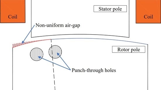
2.4. Proposed Rotor Stucture

After choosing the appropriate non-uniform section, the next step is to flatten the curve to further reduce the ripple. Figure 5 shows the design of the proposed rotor. β d i s R , β d i s H , and l d i s H are the angular distance of the first hole to the nearest pole edge, the angular distance between the holes, and the distance from the pole surface. Note that the l d i s H is constant regardless of the non-uniform part. Two small holes are placed near the surface because the closer they are to the shaft, the less their effect will be on torque development. Manufacturing accuracy is the only restriction in the model.
In order to investigate this more deeply, the non-uniform, one-hole model is investigated. The comparison of the torque and inductance of the four designs is shown in Figure 6. Two points, R and S, mark the convex area that has to be straightened from the previous non-uniform-only structure to achieve the ideal torque waveform shape. H 1 is located at “R”. It can be seen that the simple non-uniform and single hole models do not have distinct differences, as seen in the figure. However, the corner at “R” is slightly lowered in the single-hole design. The second hole and the H 2 placement create the rather square shape, which is discussed in Section 3. In any case, the symmetrical feature is retained, and so bi-directional rotation is possible. In this study, both holes have the same diameter, but it is possible to shape them in any way to create the desired waveform in accordance with the general guidelines given here. The average torque of the one-hole and proposed model for the same current excitation is 0.319 and 0.317 Nm, respectively. In other words, the proposed method has the minimum torque compared to others, with a drop of 2.16% compared the conventional approach.

3. Simulation Results

3.1. Flux Distribution

In this section, the flux paths from the stator to the rotor for points P, R, Q, and S are examined. Only the “M” type is used as illustration since the “N” type will work in the opposite manner. Both motors have the same core material, 50PN440, and the current is adjusted to obtain a similar average torque output. The summary of the point positions is given below.
Figure 7 and Figure 8 show the flux distribution of conventional and proposed motors as the rotor rotates along the circumference passing the stator pole. Each figure from (a) to (d) presents points P, R, Q, S, as described Figure 4, Figure 6, and Table 2. The subsection (e), however, is arbitrarily chosen to observe why the proposed motor has a slightly wider torque positive area, as seen in Figure 6b.
At point P, where the tips of the rotor and stator pole meet, no distinction can be made between the two models other than that the flux is more concentrated at the pole tip for the conventional model. This corresponds to Figure 4b and Figure 6b, in which the value of torque is similar for the four models.
At point R, where the torque convexity corner starts, the stator and rotor overlap in the non-uniform air-gap section. As a result, the flux density of the proposed design is lower, which leads to a lower torque value. In contrast to the conventional type, the sharp increase in torque can be reduced by avoiding high density or saturation in this area, thus obtaining a smoother slope.
After passing point R, the rotation comes to point Q, where the “torque overshoot” curve in the conventional model ends. Relative to point R, the maximum density of the conventional type is reduced here, and so is the torque value. However, this is not the case in the proposed model. The flux density level on the surface of the overlapping section is only higher than that at point R. Therefore, the torque value can be maintained. It can be seen in the figure that this is where the second hole plays an important role in keeping the rotor surface flux density the same; changing the position and/or size will affect the flatness of the torque.
Finally, the end of the convexity is at point S. Here, the average surface flux density in the overlapping section is similar in both models, which explains the torque values in Figure 6b. After point S, the 87% aligned position is chosen arbitrarily. The proposed model still has slightly higher torque compared to the conventional one, resulting in a wider positive area. The reason for this is shown in Figure 8e, where the average surface flux density of the proposed structure is higher because of the positioning of the second hole. In conclusion, the generated torque is closely related to the flux distribution in the overlapping region of the stator and rotor poles. Maintaining a similar flux density level over the excitation period means keeping a constant torque value and thus lowering the torque ripple.

3.2. Continuous Torque

Single-phase excitation alone cannot verify the reduction of the torque ripple. In this section, continuous torque is observed when all phases are excited sequentially. First, the torque ripple equation is given as a percentage of the average torque as follows:
T r i p p l e = T max + T min T a v g
Figure 9a shows the continuous torque in the proposed SRM. T min occurs at conduction when the exciting phase is turned off and the next phase is turned on. This switching action inevitably creates the inherent high torque ripple in SRM. Reducing T max and increasing T min for the same T a v g is an effective way to reduce the torque ripple. This is the main goal of the proposed structure. However, as shown before, the average torque decreases with each modification. For the torque ripple comparison, the current is adjusted so that the four models have the same average torque of 0.45 Nm. The result is presented in Figure 9b. The corresponding torque ripple is shown in Table 3. The torque ripple is reduced by 7%, and the current of the proposed model is merely 0.5 A higher than the conventional approach. It is shown that the torque of the proposed motor is much flatter at the top, with a wider positive torque area, compared to other models. This confirms that the proposed design can reduce the torque ripple with the same output capability.

4. Experimental Results

After the verification of the reduced torque ripple, the proposed motor was manufactured to evaluate its performance. The prototype of the proposed 12/8 SRM is shown in Figure 10. The punch-holes were distributed into “M” and “N” types, as previously described. The black plate attached on the rotor in Figure 10b contained small magnets. Two Hall-effect sensors were mounted on the back of the motor frame which detected these magnets for rotor position information. Compared to other encoder types, this method results in a much lighter and more compact system.
The experimental setup is shown in Figure 11a. The motor is mounted on a zig, and its shaft is coupled with a torque sensor, the other end of which is coupled with an electric clutch. By controlling the power of the electric clutch, the load torque could be induced to the motor. A 12 V power supply—corresponding to the battery supply in vehicles—was used for the motor. Figure 11b shows the overall connection diagram involved in the experiment. A microcontroller, TMS320F28335 from Texas Instruments, was used to control the PWM (Pulse Width Modulation) signal to the asymmetric converter and also read the position signal from the Hall sensors. The clutch model was an ZKG-50AN from Mitsubishi. The power to the clutch was controlled manually by adjusting the voltage of a separate DC power supply.
The experiment was performed by implementing a 100% duty cycle of PWM, also known as single-pulse control, as shown in Figure 12. The phase currents are also presented in the figure. The rated value of the proposed motor, which was 0.245 Nm at 1800 RPM, was achieved, as can be seen in Figure 12a. A much higher torque could be obtained at the lower speed level of 600 RPM, at which the motor was able to generate 0.70 Nm of output torque. Nevertheless, the maximum current was under 30 A in any condition. Finally, the speed vs. torque and efficiency curves are shown in Figure 13. The efficiencies at 1800 and 600 RPM were 70.7 and 32.5%, respectively. However, efficiency was not a necessary requirement, since the motor only rotates for a short amount of time with each shift gear command from the driver. The phase RMS (Root-Mean Square) current required to produce the torque is given in Figure 13b. All values were under 15 A and thus met the design target. Therefore, it could be confirmed that the proposed motor satisfies all the requirements presented in Table 1.
The calculation of the torque ripple is difficult to perform in real-time during an experiment. Therefore, FEM can be used to estimate the actual torque. A dynamic simulation using the SRM circuit configuration shown in Figure 1a could be set according to the experimental setup. The same control properties (initial position, excitation angle, etc.) were applied in the simulation to obtain a similar phase current to that of the experiment. Thus, the torque output of the experiment could be predicted. The result is shown in Figure 14. The experimental and simulation phase currents are shown in the top and middle plots, respectively. The resulting torque from the middle plot is shown at the bottom. The torque ripple was calculated to be 26.65%.

5. Discussions

The effectiveness of the proposed design combining a non-uniform air-gap and hole placement and its performance have been confirmed through FEM simulations and experiment. However, an optimization algorithm was not performed, and it is possible that a more optimal model could be designed. The closer the hole is to the surface, the greater the impact on the torque. If the hole is too close, however, then the structure is at risk of breaking during operation. An additional mechanical structural analysis could therefore also be useful. It is also feasible to only use one hole or more than two holes to modify the torque waveform as required. The same principle should be applied, maintaining the flux density on the surface. Another factor to be considered is that it is important to discuss how accurate the motor prototype will be with the corresponding manufacturer; in this case, this relates to the possible size of the hole and air-gap. Nevertheless, the viability of the proposed SRM as an SBW actuator is shown in this study.
SRM has a large number of advantages because of its simple structure, but the implementation of the motor in practical everyday use is still low compared to other machines. In [3,4], the authors presented a 12/8 SRM for an actual SBW application; however, the improvement of the drawbacks of SRM such as torque ripple were not clearly discussed and/or shown. Other than the design method and analysis, it is hoped that this study can guide researchers and industries to utilize and improve SRMs to make it competitive in the market.
Furthermore, various control methods can be applied to increase the performance. As can be seen in the experimental results, the phase currents have a “tail” at the end before decreasing to zero. This is due to the slightly long excitation time allowing more current to flow so that the desired torque can be reached. Even a simple turn-on and turn-off angle control method can be implemented to further reduce the torque ripple; however, this is beyond the scope of this paper.

6. Conclusions

In this paper, a rotor design to reduce torque ripple while maintaining the average torque value and bi-directional rotation is proposed. SRM is a low-cost, robust motor but suffers from relatively high torque ripple, which can hinder its performance. Low torque ripple and smooth operation are necessary for shift-by-wire applications for safety and accuracy in moving the shifting gear.
A non-uniform air-gap is utilized to reduce the “torque overshoot” which occurs in the conventional structure. This is then combined with the positioning of two holes, meaning that the average flux density at the overlapping region of the stator and rotor poles can be kept close to constant during the period of excitation. The rotor pole tip is cut in a mirrored way to maintain a symmetrical property for bi-directional rotation. FEM is used to check the characteristics of the motor, and it is shown that the torque ripple can be reduced by 7% for the same output power by modifying the design alone.
A prototype motor of the proposed design was manufactured to verify its performance. It was shown that the motor satisfied the requirement of 0.245 Nm of torque at 1800 RPM. Moreover, the maximum current was kept below 30 A. The estimated torque ripple by matching the simulation to the experimental result was shown to be low, at 26.65%. The efficiency at rated conditions was 70.7%, but this was not a requirement due to the designated application, which demands the motor only to be run for a short amount of time and not to be in continuous operation. Both simulations and experiments showed the viability of the proposed 12/8 SRM as an actuator for a shift-by-wire system.
SRM has no brushes and commutators, and so there is little—or no—problem with maintenance compared to DC and universal motors. However, compared to permanent magnet motors, the power density and efficiency are generally relatively low. SRM makes up for this with its low manufacturing cost and high robustness (due to its simple structure). When efficiency is not the main issue and a long lifespan and high robustness are prioritized, an SRM with a low torque ripple design is a good actuator candidate that can meet the output requirements, as presented in this paper.

Author Contributions

Conceptualization, X.S.N.; Data curation, G.F.L.; Formal analysis, G.F.L.; Investigation, G.F.L.; Methodology, X.S.N.; Supervision, J.-W.A.; Validation, J.-W.A.; Writing—original draft, G.F.L.; Writing—review & editing, G.F.L. All authors have read and agreed to the published version of the manuscript.

Funding

This work was supported by “Human Resources Program in Energy Technology” of the Korea Institute of Energy Technology Evaluation and Planning (KETEP), and was granted financial resources from the Ministry of Trade, Industry & Energy, Republic of Korea. (No. 20184010201700), and Kyungsung University Research Grants in 2020.

Conflicts of Interest

The authors declare no conflict of interest.

References

  1. Smirra, K.; Ferstl, M.; Eiting, T. Mechatronics for “Shift by Wire”—A Technical Challenge; SAE Technical Paper 2007-01–1309; SAE International: Warrendale, PA, USA, 2007. [Google Scholar] [CrossRef]
  2. Naunheimer, H.; Bertsche, B.; Ryborz, J.; Novak, W. Automotive Transmissions: Fundamentals, Selection, Design and Application, 2nd ed.; Springer-Verlag: Berlin/Heidelberg, Germany, 2011. [Google Scholar] [CrossRef]
  3. Kobiki, Y.; Inoue, Y.; Sekiguchi, S.; Itoh, T.; Kamio, S. Toyota’s New Shift-by-Wire System for Hybrid Vehicles; SAE Technical Paper 2004-01–1112; SAE International: Warrendale, PA, USA, 2004. [Google Scholar] [CrossRef]
  4. Nakade, Y.; Kamada, A.; Ueno, K.; Kume, M.; Sakaguchi, K. Shift-by-Wire System for Lexus RWD Vehicles. SAE Int. J. Engines 2017, 10, 689–694. [Google Scholar] [CrossRef]
  5. Ahn, J.-W.; Lukman, G.F. Switched Reluctance Motor Drives. Modeling Simul. Control Electr. Drives 2019, 275–324. [Google Scholar] [CrossRef]
  6. Choi, Y.K.; Yoon, H.S.; Koh, C.S. Pole-Shape Optimization of a Switched-Reluctance Motor for Torque Ripple Reduction. IEEE Trans. Magn. 2007, 43, 1797–1800. [Google Scholar] [CrossRef]
  7. Hieu, P.T.; Lee, D.-H.; Ahn, J.-W. Design of 2-Phase 4/2 SRM for Torque Ripple Reduction. In Proceedings of the 2012 15th International Conference on Electrical Machines and Systems (ICEMS), Sapporo, Japan, 21–24 October 2012; pp. 1–6. [Google Scholar]
  8. Sheth, N.K.; Rajagopal, K.R. Optimum Pole Arcs for a Switched Reluctance Motor for Higher Torque with Reduced Ripple. IEEE Trans. Magn. 2003, 39, 3214–3216. [Google Scholar] [CrossRef]
  9. Jing, L.; Cheng, J. Research on Torque Ripple Optimization of Switched Reluctance Motor based on Finite Element Method. Prog. Electromagn. Res. 2018, 74, 115–123. [Google Scholar] [CrossRef] [Green Version]
  10. Salunke, N.A.; Patel, A.N.; Panchal, T.H. Torque Ripple Reduction of Switched Reluctance Motor by Changing the Rotor Pole Tip Radius. IJRTE 2019, 8, 4256–4259. [Google Scholar] [CrossRef]
  11. Zhang, H.; Wang, S. Topology Optimization of Rotor Pole in Switched Reluctance Motor for Minimum Torque Ripple. Electr. Power Compon. Syst. 2017, 45, 905–911. [Google Scholar] [CrossRef]
  12. Nakata, K.; Hiramoto, K.; Sanada, M.; Morimoto, S.; Takeda, Y. Noise Reduction for Switched Reluctance Motor with a Hole. In Proceedings of the Power Conversion Conference-Osaka 2002 (Cat. No.02TH8579), Osaka, Japan, 2–5 April 2002; Volume 3, pp. 971–976. [Google Scholar] [CrossRef]
  13. Faiz, J.; Tahvilipour, F.; Shahgholian, G. Performance Improvement of a Switched Reluctance Motor. In Proceedings of the 31st Progress in Electromagnetics Research Symposium (PIERS), Kuala Lumpur, Malaysia, 27–30 March 2012; pp. 728–732. [Google Scholar]
  14. Tekgun, D. Acoustic Noise and Vibration Reduction on Switched Reluctance Machines through Hole Placement in Stator/Rotor Laminations. Master Thesis, The University of Akron, Akron, OH, USA, 2017. [Google Scholar]
  15. Dickinson, P.G.; Sykes, P.A.; Fulton, N.N.; Durairaj, T.R. Reducing Stress in Electric-Machine Rotors by Optimizing Holes. U.S. 9,246,363, 26 January 2016. [Google Scholar]
  16. Hashemi, Z.; Zohrabi, F.; Mardaneh, M. A Multi-Objective Optimization of Switched Reluctance Motor Using a Hybrid Analytic-ANFIS Model Considering the Vibrations. Iran. J. Sci. Technol. Trans. Electr. Eng. 2019, 43, 361–371. [Google Scholar] [CrossRef]
  17. Zhang, S.; Li, S.; Harley, R.G.; Habetler, T.G. Performance Evaluation and Comparison of Multi-Objective Optimization Algorithms for the Analytical Design of Switched Reluctance Machines. CES Trans. Electr. Mach. Syst. 2017, 1, 58–65. [Google Scholar] [CrossRef]
  18. Zhang, J.; Wang, H.; Zhu, S.; Lu, T. Multi-Physics Multi-Objective Optimal Design of Bearingless Switched Reluctance Motor Based on Finite-Element Method. Energies 2019, 12, 2374. [Google Scholar] [CrossRef] [Green Version]
  19. Schramm, D.S.; Williams, B.W.; Green, T.C. Torque Ripple Reduction of Switched Reluctance Motors by Phase Current Optimal Profiling. In Proceedings of the PESC ’92 Record. 23rd Annual IEEE Power Electronics Specialists Conference, Toledo, Spain, 29 June–3 July 1992; Volume 2, pp. 857–860. [Google Scholar] [CrossRef]
  20. Liang, J.; Parsapour, A.; Moallem, M.; Fahimi, B.; Kiani, M. Torque Profile Optimization in Switched Reluctance Motor. In Proceedings of the 2019 IEEE 28th International Symposium on Industrial Electronics (ISIE), Vancouver, BC, Canada, 12–14 June 2019; pp. 414–419. [Google Scholar]
  21. Nakayama, S.; Itoh, T.; Kimura, K. Switched Reluctance Motor. U.S. 7,948,145, 24 May 2011. [Google Scholar]
  22. Krishnan, R. Switched Reluctance Motor Drives: Modeling, Simulation, Analysis, Design, and Applications; CRC Press: Boca Raton, FL, USA, 2017. [Google Scholar]
Figure 1. (a) General 12/8 switched reluctance motor (SRM) with parallel winding connection and (b) constant current excitation.
Energies 13 02329 g001
Figure 2. Conventional 12/8 SRM: (a) 2D model and (b) characteristics.
Energies 13 02329 g002
Figure 3. Bi-directional non-uniform structure: (a) pole distribution and (b) modeling.
Energies 13 02329 g003
Figure 4. Comparison of conventional and non-uniform air-gap models: (a) torque and (b) inductance.
Energies 13 02329 g004
Figure 5. Proposed rotor structure: (a) pole distribution and (b) modeling.
Energies 13 02329 g005
Figure 6. Comparison of the four models: (a) inductance and (b) torque.
Energies 13 02329 g006
Figure 7. Flux density of conventional type: (a) point P, (b) point R, (c) point Q, (d) point S, (e) 87% aligned.
Energies 13 02329 g007aEnergies 13 02329 g007b
Figure 8. Flux density of proposed motor: (a) point P, (b) point R, (c) point Q, (d) point S, (e) 87% aligned.
Energies 13 02329 g008
Figure 9. Continuous torque: (a) conventional 12/8 SRM and (b) comparison.
Energies 13 02329 g009
Figure 10. Manufactured motor: (a) stator and (b) rotor.
Energies 13 02329 g010
Figure 11. Experimental setup: (a) test bed and (b) connection diagram (eCAP—enhanced capture; MCU—microcontroller unit).
Energies 13 02329 g011
Figure 12. Experimental result: (a) 1800 RPM–0.245 Nm and (b) 600 RPM–0.70 Nm.
Energies 13 02329 g012
Figure 13. Performance curves: (a) speed vs. torque, efficiency and (b) speed vs. torque, phase current RMS.
Energies 13 02329 g013
Figure 14. Comparison of phase currents and estimated torque.
Energies 13 02329 g014
Table 1. Design parameters.
ParametersValue
Stator outer diameter (mm)75
Stack length (mm)18
Air-gap length (mm)0.25
DC-link voltage (V)12
Maximum phase current (A)30
Rated speed (RPM)1800
Rated torque (Nm)0.24
Table 2. Selection of point location.
PointDefinition
PStart of overlap between rotor and stator
RStart of “torque overshoot” corner
QEnd of “torque overshoot” corner
SEnd of convexity of torque waveform
Table 3. Torque ripple comparison.
DesignPhase Current (A)Torque Ripple (%)
Conventional13.568.81
Non-uniform13.765.16
Non-uniform, one-hole13.864.27
Proposed14.061.77

