Article

Nucleate Pool Boiling Heat Transfer from High-Flux Tube with Dielectric Fluid HFE-7200

1
Department of Mechanical Engineering, National Chiao Tung University, Hsinchu 300, Taiwan
2
Green Energy & Environment Research Laboratories, Industrial Technology Research Institute, Zhudong 310, Taiwan
*
Author to whom correspondence should be addressed.
Energies 2020, 13(9), 2313; https://doi.org/10.3390/en13092313
Submission received: 21 April 2020 / Revised: 5 May 2020 / Accepted: 5 May 2020 / Published: 6 May 2020
(This article belongs to the Special Issue Experimental Heat Transfer in Energy Systems)

Abstract

:
In the present experimental study, nucleate pool boiling heat transfer measurements of two high-flux tubes (sample A and sample B) were conducted at atmospheric pressure with HFE-7200 as the working fluid. Both high-flux tubes were made from a sintered Cu-Ni (high-flux) alloy powder. The porous high-flux surface was coated inside the test tube and it is tested within the heat flux ranging from 2.6 to 86 kW/m2. The major difference between sample A and sample B was the coating thickness, where sample B (0.6 mm) was much larger than that of sample A (0.07 mm). Both tubes showed about three times enhancement in heat transfer coefficient (HTC) when compared to plain tube. Even though sample B contained a higher HTC than sample A, it also revealed a faster level-off phenomenon regarding the HTC vs. wall superheat. The major parameter which characterizes the boiling performance of high-flux tube was the ratio of coating thickness to pore diameter which also yielded different trends upon HTC vs. wall superheat amid sample A and B. It was found that the porous based Nishikawa correlation can well predict the performance of sample A but not sample B. This is because the ratio of coating thickness to pore diameter is far outside the applicable range of the Nishikawa correlation. Hence, a modified Nishikawa correlation is proposed. The predicted capability of the proposed modified Nishikawa correlation against sample A and sample for HTC was within ±28% deviation. The standard mean deviation of the Nishikawa correlation with experimental data for sample A and sample B was 0.302 (12.48%) and 5.64 (73%), respectively.

1. Introduction

One of the main components in the heat removal system is the heat exchanger that carries out heat transfer via sensible or latent heat during the heat transport process. Heat transfer via latent heat (e.g., boiling with evaporators) is considered as one of the most efficient ways of transporting huge amounts of thermal energy. Nucleate boiling from the porous-coated surface has been investigated for a long time since it has the capability of attaining high heat flux while maintaining a low wall superheat. In 1964, the porous-coated surface, called the high-flux surface, was initially introduced and patented by Milton (1968) [1]. The high-flux tube is characterized by a thin porous metal layer, which is bonded metallurgically to the heat transfer surface, and it is specifically designed to enhance heat transfer performance in association nucleate boiling subject to low wall superheat (e.g., Δ T = 5 °C). Due to the low wall superheat, stable boiling heat transfer can be achieved, and it can reduce the effective mean temperature difference of the heat exchanger to reduce utility consumption.
With the gigantic rise in heat flux in a large heat transfer system, a highly efficient thermal management system becomes imperative and the high-flux tube has shown potential to augment the heat transfer at low wall superheat and reduce the size of the heat exchanger equipment. A high-flux tube can be manufactured by sintering, spraying, and machining. Among them, the sintered high-flux tube is comparatively more efficient but more costly due to its complex manufacturing processing method. There are numerous applications of the high-flux tube in phase change equipment, such as carburetor, evaporator, and condenser, etc., with working fluids, such as dielectric fluid, ethylene glycol, light olefin, refrigerant, liquid oxygen, liquid nitrogen. Note that the high-flux surface features a porous roughness upon the base tube materials.
Since 1968 many studies have been conducted in terms of the major influential geometric parameters (e.g., porosity, shape, and size of the particle, coating thickness, pore size, and roughness) for the porous-coated boiling surface. Webb [2] summarized some prior works [3,4,5,6,7,8,9,10] for a variety of particle shape, size, and coating thickness with the spherical particle diameter of 44 < d p < 1000 µm and the coating thickness were 0.25 < δ < 2 mm. He found that the particle diameter has a minor effect on boiling performance, but good performance is attained with a coating thickness of around 3–6 particle diameter. Webb [2] also compared the effect of geometric variables of seven porous coated surfaces with R-11, and he found that the particle diameter imposes a negligible effect on heat transfer performance when the coating is made of high conductivity particles (copper), but the maximum boiling coefficient occurs when δ / d p ≈ 4. For lower thermal conductivity particles, such as bronze, the performance is not sensitive to the ratio of coating thickness to particle diameter in the range of 2 < δ / d p < 6. However, matrix porosity has a significant effect on the boiling coefficient, and matrix porosity should be independent of particle diameter when the coating is made of uniform diameter spherical particles. Nishikawa et al. [8] observed that the boiling performance is decreased with copper sintered coating provided that the coating thickness to particle diameter exceeds four. Nakayama et al. [11] studied the effects of pore diameters and system pressure on the saturated pool nucleate boiling heat transfer for the porous surface with R-11. Pore diameters were 50–150 µm and the system pressure was 0.04–0.23 MPa. The surface having a pore size of 100 µm or 150 µm showed excellent heat transfer performance at the system pressure of 0.23 MPa. At low levels of heat flux, pores of the largest size play significant roles in heat transfer. The influence of surface roughness on nucleate boiling heat transfer was investigated by [12,13,14,15,16]. The major conclusion from these studies indicates that increases in the surface roughness enhance the number of active nucleation sites, hence increase the heat transfer coefficient (HTC).
The aforementioned studies were focused on working fluids, such as refrigerants and water. For working fluids containing very low surface tension with high wetting characteristics, such as the dielectric fluid, some different heat transfer characteristics may prevail when compared to poorly wetting fluid. It was noticed that highly wetting fluid may significantly enhance the critical heat flux and reduces the wall superheat of the boiling surface [17]. Some representative studies concerning the boiling performance for porous surfaces are outlined in the following.
Sarangi et al. [18] investigated the pool boiling of FC-72 using porous surfaces coated with a layer of sintered copper particles having irregular and spherical morphologies of different porosities (40%–80%). The HTCs of the irregular particle is higher when compared to the spherical particle at similar porosity, and a higher porosity reduces the HTC. Ramaswamy et al. [19] investigated the effect of varying the pore size (90–320 µm), pitch, and height on the boiling performance with fluorocarbon FC-72. The largest pore size showed maximum heat dissipation, and a reduction in pitch also led to the significant rise of heat dissipation. Yet a larger pore and smaller pitch resulted in higher heat dissipation at all heat flux. Chang and You [20] compared the boiling performance of a microporous enhanced surface (ABM, CBM, DBM, DOA, SOA) with that of the commercial high-flux surface in a pool of saturated FC-72 at atmospheric pressure. They found that the high-flux surface yielded better performance than the microporous enhanced surface at lower heat flux. Chun and Kang [21] investigated the effects of heat exchanger parameters (tube diameters, surface roughness, and tube orientations) on nucleate pool boiling heat transfer in vertical and horizontal orientations. They found that increased surface roughness increases the heat transfer for both horizontal and vertical orientations, and the effect of surface roughness is more pronounced for the vertical tubes compared to the horizontal tubes. The heat transfer rate is decreased as the tube diameter is increased, and this is applicable for both horizontal and vertical tubes. However, the effect of tube diameter on the nucleate pool boiling heat transfer for vertical tubes is greater than that for horizontal tubes. Jones et al. [22] studied a wide range of roughness with water and FC-77. The tested surfaces are from ( R a = 0.027–0.038 µm) to ( R a = 1.08–10.0 µm). For FC-77, the HTC was found to continuously increase with increasing roughness, and the roughest surface showed the highest HTC.
Recently, Cao et al. [23,24] studied the pool boiling of HFE-7200 with nanoparticle (Cu-Zn ~100 nm) coating (e.g., modulated nanoparticle coating and uniform nanoparticle coating) and they observed that modulated surface could enhance the HTC and the critical heat flux by 60% and 20%–40%, respectively, in comparison to the smooth surface, while the uniform coating surface can improve HTC by a maximum 100% but shows no augmentation in the critical heat fluxes.
From the preceding literature review, it was observed that the nucleate pool boiling heat transfer of the porous-coated surface is generally outside the tube. Notice that the commercially available high-flux coated surface is applicable in either outside tube or inside the tube. In this regard, it is the objective of this study to examine the nucleate boiling of the high-flux surface inside the tube in association with dielectric fluids. The dielectric fluid for examination in this study is HFE-7200, which is one of the attractive fluids for offering the benign environmental features. Yet it is chemically stable with high dielectric strength that is well suited for high power electronic cooling [25]. The corresponding thermophysical properties of HFE-7200 are listed in Table 1.

2. Experimental Method and Procedure
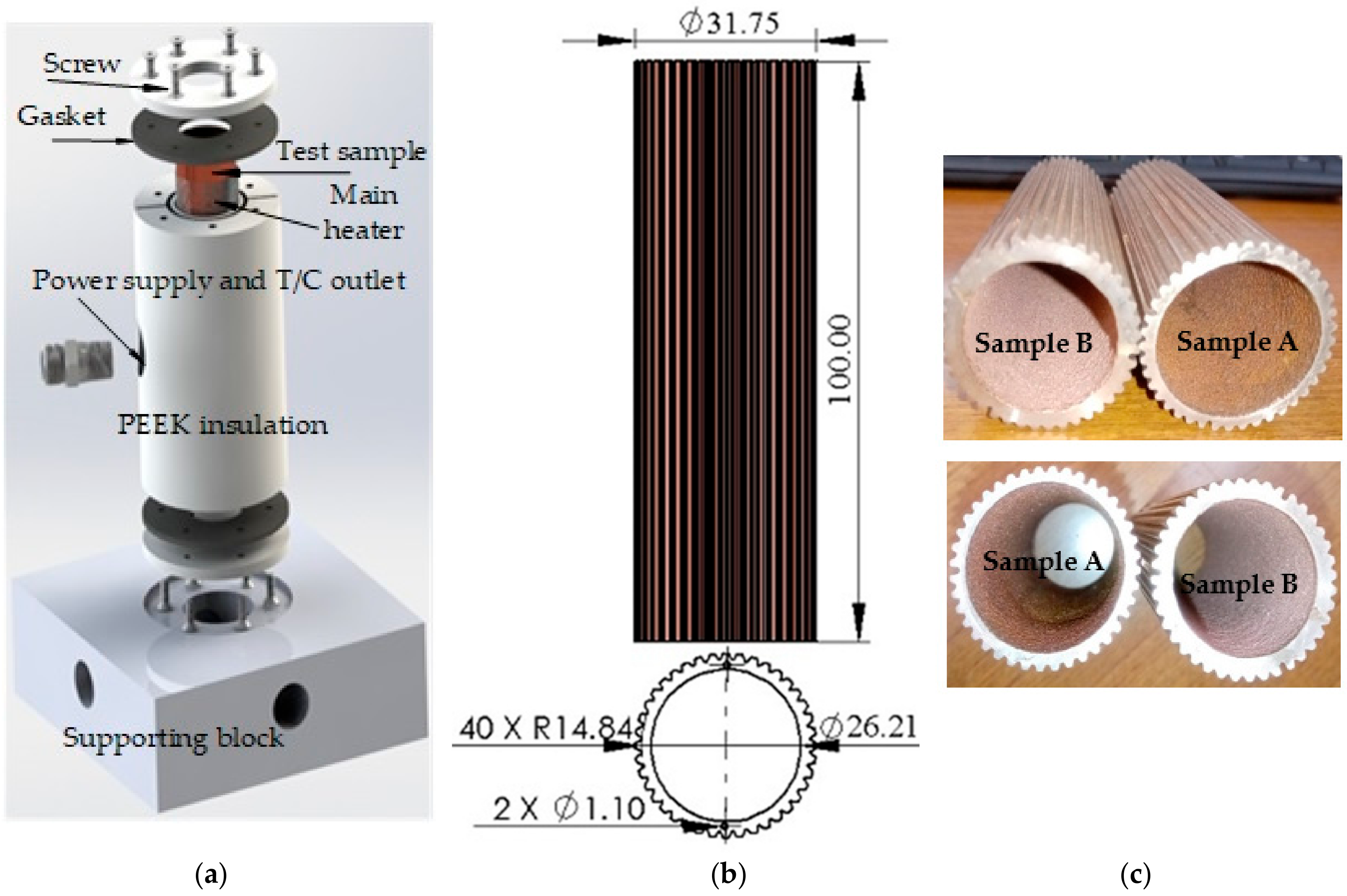
2.1. Test Apparatus

The pool boiling test facility used for the present study is shown in Figure 1. The main components of the experimental system included a PMMA vessel (height 600 mm and diameter 380 mm), test section, supporting block, preheater (800 W), main heater (1200 W), AC power supply unit, condenser, thermostat tank, GM-10 data acquisition, and a personal computer was used to collect the data and for further analysis.
The pool boiling experiments were conducted at the atmospheric pressure and saturation temperature, using HFE-7200 as a working fluid. The working fluid (HFE-7200) was contained within the PMMA vessel, and its saturation temperature was maintained by an 800 W preheater, which was installed at the bottom of the test vessel. A water-cooled condenser was installed at the upper part of the test vessel to condense and re-circulate the working fluid. Atmospheric pressure was maintained by the safety valve of the test vessel to ambient during the pool boiling experiment. Two T-type thermocouples were fitted inside the test vessel to measure the bulk temperature of the working fluid. GM-10 data logger (Yokogawa, Japan) was used to collect and convert the signal from temperature and pressure reading.

2.2. Test Section

Assembly of the test section and test sample used in the present study are shown in Figure 2. Test section assembly was vertically mounted to a supporting block (150 mm × 150 mm × 150 mm) and immersed in the test liquid. The test section was 100 mm long with internally coated copper alloy powder. The material of the test tube was made from copper–nickel (90/10) alloy. Two thermocouple holes were drilled on top of the tube to house two shielded T-type thermocouple, and the thermocouples were spaced 180 degrees apart. Note that the diameter and length of the drilled hole were 1.1 mm and 15 mm, respectively. A 1200 W cylindrical (coiled) heater was wrapped over the test sample with 31.75 mm in diameter and 90 mm in length. A 20 mm thick insulation of PEEK material was wrapped over the main heater and the test sample to ensure the electrical and thermal insulation. A 2.5 mm gasket and 2.5 mm block were put top and bottom of the test samples. Additional four holes having 1.7 mm in diameter and 45 mm in length were drilled alongside the radial direction of insulation PEEK. The purpose of these four thermocouples was to measure the heat loss via Fourier conduction law. All the T-type thermocouples were calibrated to measure the uncertainty of 0.2 °C. The two high-flux tubes were provided from the Formosa Heavy Industries Corporation and designated as sample A and sample B. Note that the manufacturers of sample A and sample B were different.
Scanning electron microscope (SEM) images of the high-flux test samples at different magnifications (samples A and B) are shown in Figure 3. By using ImageJ software, the number of nucleation sites, nucleation site density, porosity, particle diameter, pore size, and circularity of the sintered particle was analyzed and listed in Table 2. Analysis of each sample shows that coating thickness, surface roughness, and nucleation site density of sample B was higher than sample A. However, porosity, pore size, particle circularity, particle diameter, and tube diameter of sample B was less than that of sample A. The high-flux surface characteristically contained numerous nucleation sites due to the sintered porous coating of the copper alloy powder. Nucleation site density was calculated by the following equation [26]:
N u c l e a t i o n   s i t e   d e n s i t y   =   N o .   o f   n u c l e a t i o n   s i t e t o t a l   h e a t e d   a r e a
The pore radius of the porous-coated surface was calculated by the following equation [1]:
r c = 2 σ ρ g h
where ρ is the density of the working fluid, σ is the surface tension of the working fluid, and h is vertical capillary rises of the working fluid along the porous boiling surface, g is gravity acceleration.

2.3. Test Procedure

The test section was vertically mounted on the PEEK supporting block and immersed in the pool of the dielectric fluid. The level of the working fluid was maintained 80 mm above from the top of the test section to prevent any disturbance caused by the vapor/bubble. The working fluid HFE-7200 was heated to the saturation temperature by the preheater. Once the working fluid reached its saturation temperature, an additional heating period lasting for 2 hours to remove the dissolved non-condensable gas was undertaken. The thermostat was maintained at 10 °C to condense the generated vapor from the heating surface. Subsequently, the main heater was turned on, and power was increased in small steps. Once the steady-state was reached, all the signals from the measurements of temperature, pressure, and power supply were recorded by the GM-10 data logger unit and WT-230 (YOKOGAWA power meter, Yokogawa Electric Corporation, Japan), respectively. The entire measurement procedure was repeated three times for each sample. The pool boiling experiment was conducted to a maximum heat flux of 85,830 W/m2.

2.4. Data Reduction and Experimental Uncertainty

Power supplied to the main heater was calculated by the following equation:
Q p = I V
where I and V are the input current and voltage, respectively. Heat loss from the test section was calculated by using the following equation:
Q l = 2 π k L T i T o ln r o r i
where, r o is the outside radius of insulation, r i is the inside radius of insulation, k is the thermal conductivity of insulating material, T i is the temperature near inside radius of the insulation, T o is the temperature near the outside radius of the insulation, L is the thickness of the insulation. For each high-flux tube, the surface area used to determine heat flux was based on the inner diameter of the high-flux tube, and it was calculated by using the following equation:
q = Q p Q l A i = h i T w T s = h i Δ T
where hi is the HTC inside the surface of the tube, q is the heat flux through the heating surface, ΔT is wall superheat, Q p is power supplied, Ai denotes inside surface area of the tube. The boiling HTC of HFE-7200 on the heating surface hi was calculated by Equation (5). The relative error in the heat transfer coefficient was calculated by the following equation:
Δ h i h i = δ q q 2 + δ Δ T Δ T 2
Heating power input to the heating surface, Q p was measured by YOKOGAWA WT-230 digital power meter and relative uncertainty in the heat flux was calculated by the following equation:
δ q q = δ Q p Q p 2 + δ d d 2 + δ l l 2 = 1 % 2 + 0.023 % 2 + 0.0045 % 2 = 1 %
The calibrated uncertainty of the copper-constantan thermocouple was 0.2 °C and the precision of Pt100 were 0.185 °C Therefore, the temperature difference absolute error was 0.23 °C. The smallest wall superheat ( Δ T ) was 2.5 °C. So, the relative uncertainty in wall superheat was:
δ Δ T Δ T = 0.23 2.5 × 100 % = 9.2 %
The maximum uncertainty in the heat transfer coefficient was:
Δ h i h i = 1 % 2 + 9.2 % 2 = 9.25 %

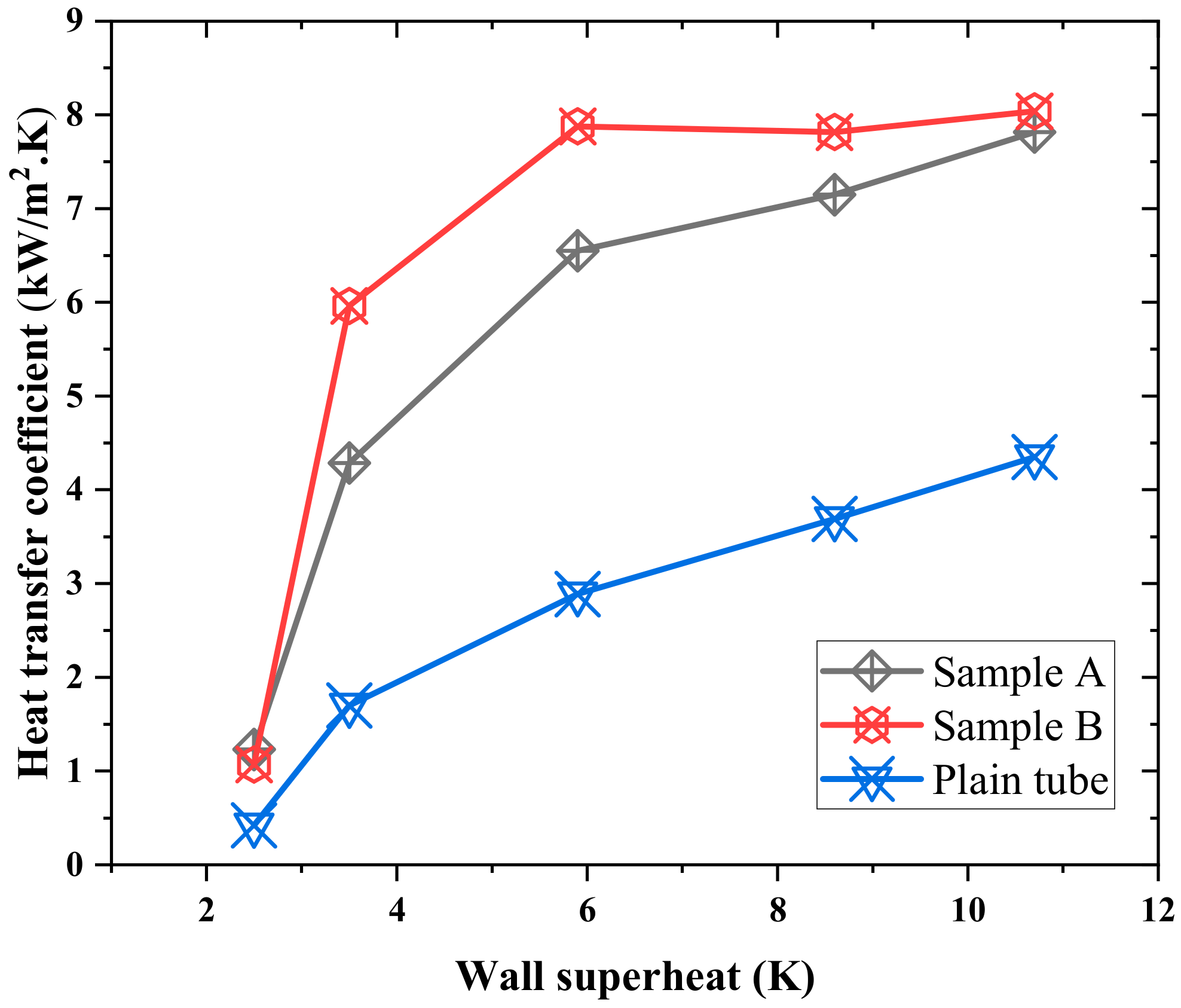
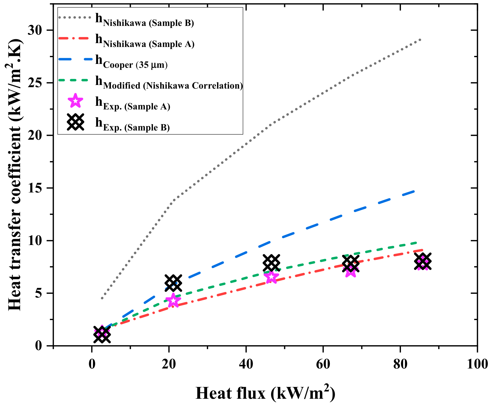
3. Results and Discussion

The experiment was carried out at the atmospheric pressure of internally porous-coated high-flux tubes in saturated HFE-7200 for comparison purposes. The typical pool boiling curve with heat flux vs. wall superheat is shown in Figure 4. It was noticed that a larger incipient boiling wall superheat was required for a high-flux surface having a low surface roughness (30.82 µm, sample A) than the high surface with a larger roughness (35.03 µm, sample B). Note that the influence of different surface roughness on the nucleate boiling surface for HFE-7200 is also reported by Tran et al. [27], whose roughness falls between 0.45–9 μm and is made by either polished or rough machining methods. Their results showed that a heat flux of 80 kW/m2 is attainable at a wall superheat about 27 °C for R a = 9 μm (a rough machining surface). Similarly, Cao et al. [23,24] presented the influence of nanoparticle coating on nucleate pool boiling with HFE-7200, and their result showed that a heat flux of 80 kW/m2 is attainable at a wall superheat about 13.5–15 °C. On the other hand, as can be depicted in Figure 4, either sample A or sample B offered the same heat flux at just about 10 °C wall superheat. Apparently, this is associated with the porous nature of the high-flux surface, which incorporated more nucleation sites onto the surfaces. From the visualization of the boiling process, at a low heat flux about 1–2.5 kW/m2, some tiny bubbles were generated from the entire heated surface for both the test samples, as shown in Figure 5. These tiny bubbles at the low heat flux region detached from the heating surface and rose freely in a separate way without apparently merging. On the other hand, when the heat flux was further raised, say q ≥ 5 kW/m2, more nucleation sites were activated, thereby resulting in more bubbles are generated from the porous surface as shown in Figure 6. The detached bubbles easily caught the prior, leaving bubbles to yield large bubble columns, and this phenomenon became more pronounced with the rise of heat flux.
The HTCs vs. wall superheats subject to heat flux is shown in Figure 7. As shown in the figure, the heat transfer enhancement at the low heat flux region can be as high as almost three times relative to the plain tube. The enhancement of the HTC depends on the morphology of the tested high-flux tube (sample A and sample B), which is listed in Table 2.
The morphological analysis of the high-flux tubes revealed that porosity ( ε ), the pore size ( r c ), particle diameter ( d p ), and circularity of the particle of sample B were 7.15%, 19.8%, 12.3%, and 2.5%, respectively, which were somehow less than sample A. On the other hand, roughness (~13.7%), coating thickness (~757%), and nucleation site density (~26%) of sample B was higher than sample A. Note that the rise of HTC between sample A and B was not the same. There were two regions of the heat transfer mechanism observed during the pool boiling test of high-flux tubes. Namely the low heat flux region ( q ≤ 50 kW/m2) and high heat flux region ( q ≥ 50 kW/m2). In the low heat flux region, the HTC increased expeditiously after the incipience boiling for both the samples up to the wall superheat ( Δ T ) 2.4–3.5 °C and 3.5–5.9 °C, respectively. In this region, sample B showed a maximum improvement in HTC of approximately 24% when compared to sample A. From Table 2, the major difference between samples A and B was the coating thickness and pore diameter. Note that sample B contained a coating thickness ( δ ) of 0.6 mm, while the δ for sample A was just 0.07 mm. In the meantime, the pore radius for samples A and B was 478 μm and 399 μm, respectively. A larger coating thickness or a smaller pore diameter apparently offers more nucleation sites to initiate effective boiling. This can be made clear from the experimental results of the microporous surface using water by Jung et al. [28]. Although more nucleation sites can initiate the boiling process effectively, it also raises some significant flow resistance that may inhibit the bubble from detaching the surface, and the re-filling liquid into the porous channel may also be impaired by the bubble incipience. This negative influence resultant from larger coating thickness and smaller pore diameter was further accentuated when the heat flux was increased. In essence, at lower heat flux, the sintered porous coating can effectively increase the nucleation site density and liquid agitation by the bubble. However, the plateau of the enhancement was soon reached at a high-flux regime due to appreciable vapor flow resistance and incapable liquid refilling. This was made clear in the high heat flux region ( q ≥ 50 kW/m2) for sample B. On the other hand, sample A which contained larger pore radius and a much lower coating thickness did not suffer appreciably and still showed a moderate rise of HTC with the rise of wall superheat. The enhancement of the HTC of sample B relative to sample A was reduced from 24% to 6%. For the sintered porous-coated surface and roughest surface, similar results were also observed by some references [18,21,29]. According to the Milton patent [1], the performance of the pore/cavity can be described and predicted by the well-known Gibbs and Clapeyron equations which relate the thermal potential required for growth of a bubble (in terms of the superheat of the liquid surrounding the bubble) to the size of the bubble.
The required superheat to initiate bubble growth ( T i T s ) is reduced by increasing r c , and hence, pore radius should be as large as possible, which can still retain the entrapped gas or vapor to activate the nucleation sites. But due to the effect of the film ( Δ T = T w T i ), it has been reported to increase as r c is increased, an effect opposite to that observed for the superheat T w T s . This phenomenon happens when the equivalent pore radius r c is greater than 0.1143 mm, as suggested by Milton [1]. In this study, the equivalent pore radius r c of sample A and sample B were 0.399 mm and 0.478 mm, respectively. In this regard, the thermal resistance induced by the film over the porous-coated surface and liquid–vapor interface surrounding the bubble may suppress the boiling HTC at the high-flux region. For the commercial tube surface, a roughness of 0.3 µm was suggested by [30,31]. Figure 7 compares the results of each of the high-flux tubes to the plain tube. The HTC of the high-flux tube was 2.5–3 times higher than that of the plain tube.
The experimental results were compared with the Cooper [30] and the Nishikawa correlation [8] at different heat flux, as shown in Figure 8. The HTC of the smooth tube and high-flux tube with working fluid HFE-7200 for the Cooper correlation [30,31] is given as:
h c = 90 q 0.67 M 0.5 p r m log 10 p r m 0.55
m = 0.12 0.2 log 10 R a
where q is the heat flux, p r is the reduced pressure, M is the molecular weight of the working fluid, R a is the surface roughness, and h c is the HTC.
The HTC of the high-flux tube (sample A and sample B) was also estimated by the Nishikawa correlation, which was developed especially for the sintered coated porous surface [8]:
q δ k m T w T s = 0.001 σ 2 λ q 2 δ 2 0.0284 δ d p 0.56 q d p ε h f g μ v 0.593 k l k m 0.708 ρ l ρ v 1.67
k m = k l + 1 ε k p
Range of applicability for Nishikawa correlation:
  • 0.1 < d p (mm) < 1
  • 1.6 < δ / d p < 20
  • 0.38 < ε < 0.71
  • 61 < k p (W/m⋅K) < 372
The experimental results of the high-flux tubes were in line with the Cooper correlation in the range of low wall superheat, i.e., Δ T = (2.5–4.5 °C). Copper correlation predicted the HTCs with a mean error of ± 17% in the low heat flux region, and the deviation was enlarged to 48% at the high-flux region. The departure of the present Cooper correlation was expected for the main database was not from the porous structure, and does not contain the influence of coating thickness. Whereas, the Nishikawa correlation (specially developed for the sintered particle coating) well predicted the HTC in the entire region of the boiling curve with the mean error of ± 15% for sample A, as shown in Figure 8. But for sample B, it over-predicted the HTC by 66% because the correlation was limited to 1.6 < δ / d p < 20, and sample B contained a much higher value of the ratio of coating thickness to pore diameter ( δ / d p = 30.82). In contrast, the actual average HTC enhancement of sample B compared to sample A was only 11%. The level-off of HTC for sample B has been explained in the aforementioned section.
From the experimental results, it was noticed that increasing coating thickness to particle diameter ratio ( δ / d p ) in the range from 20 to ~ 32 did not offer appreciable enhancement on HTC, which was opposite to the prediction by the Nishikawa correlation. It signifies that the influence of δ / d p is diminishing when the ratio is increased to a certain threshold, yet this effect is also associated with the supplied heat flux. The corresponding influence gradually died out with the rise of ( δ / d p ) and heat flux. As mentioned earlier, Equation (12) is valid for δ / d p < 20. To extend the applicability of the Nishikawa correlation, efforts were made to modify the original correlation. The modified correlation is not only valid in its original range but also can extend to a higher δ / d p up to 32. The proposed modified form of Nishikawa correlation is the following:
q δ k m T w T s = 0.001 σ 2 h f g q 2 δ 2 0.0284   +   C 1 δ d p 0.560   +   C 2 q d p ε h f g μ v 0.593 k l k m 0.708 ρ l ρ v 1.67
where C 1 and C 2 are defined as follows:
C 1 =   0.081 +   0.0244 log 10 σ 2 h f g q 2 δ 2
C 2 = 0.448 + 0.141 log 10 δ d p
Range of applicability for the modified Nishikawa correlation:
  • 100 (nm) < d p < 1 (mm)
  • 1.6 < δ / d p < 32
  • 0.38 < ε < 0.71
  • 61 < k p (W/m⋅K) < 372
As seen in Figure 9, the predicted capability of the proposed modified Nishikawa correlation against sample A and sample for HTC was within ± 28% error. The standard mean deviation of the Nishikawa correlation with experimental data for sample A and sample B was 0.302 (12.48%) and 5.64 (73%), respectively. Whereas the standard mean deviation of sample A and sample B with the modified form of Nishikawa correlation and experimental data was 0.302 (12.48%) and 0.534 (20%), respectively.
A comparison from four experimental data sources [23,24,32,33] with modified Nishikawa correlation is shown in Figure 10. The original Nishikawa correlation was tested for only refrigerant R-11 and R-113, but the modified form of Nishikawa correlation showed good agreement with other working fluids (HFE-7200, FC-72, and water). The standard deviation of the predicted value (4.843) against the experimental value (4.715) was 0.129, with a ± 28% deviation.

4. Conclusions

In this paper, an experimental study concerning the pool boiling performance for two high-flux tubes was conducted with dielectric fluid HFE-7200 at atmospheric pressure. The internal diameter of the high-flux tubes was 26.07 mm (sample A) and 23.74 mm (sample B) with sintered porous coating inside the tube and was placed vertically for testing. The major difference between sample A and sample B was the coating thickness of sample B (0.6 mm) was much larger than sample A (0.07 mm). The experimental results showed that the high-flux tubes yield superior performance, especially at the low wall superheat ( Δ T = 2.4–5 °C). The high-flux tubes offer 2.5–3 times higher HTC than the plain tube. Although sample B contained a higher HTC than that of sample A, it also revealed a faster level-off regarding the HTC vs. wall superheat, while sample A did not show an appreciable level-off phenomenon. This is because a larger coating thickness provides more nucleation sites to facilitate high boiling performance effectively in low wall superheat. However, it also contains some drawbacks; the detachment of bubbles from the heating surfaces and refilling the liquid into the porous structure, and these phenomena were further accentuated at the high-flux regime. It was found that the porous based Nishikawa correlation can well predict the performance of sample A but not for sample B. This is because the ratio of coating thickness to pore diameter for sample B is far away from the applicable range of the Nishikawa correlation. In this regard, efforts were made to extend the predictive ability of the Nishikawa correlation. The proposed modified correlation was based on the Nishikawa correlation but can predict the HTC subject to a much larger ratio of coating thickness to pore diameter. The predicted capability of the proposed modified Nishikawa correlation against sample A and sample B for HTC was within ± 28% deviation. The standard mean deviation of the Nishikawa correlation with experimental data for sample A and sample B was 0.302 (12.48%) and 5.64 (73%), respectively.

Author Contributions

All the authors have contributed their efforts to complete the paper. A.K. prepared and analyzed the data and also wrote the first draft, K.-S.H. supervised the project, and C.-C.W. wrote and edited the manuscript. All authors have read and agreed to the published version of the manuscript.

Funding

This research was funded by the Ministry of Science and Technology Taiwan under, grant number 108-2622-E-009-004-CC2, and the funding from the Ministry of Economic Affairs, Taiwan by K.-S. Hong.

Acknowledgments

The author would like to thank Formosa Heavy Industries Corp. for their assistance in obtaining samples of the high-flux tube tested during the study. The second author (K.-S. Hong wishes to acknowledge support from the Ministry of Economic Affairs, Taiwan).

Conflicts of Interest

The authors declare no conflict of interest.

Nomenclature

A i surface area, m2
D i inside diameter, m
d p particle diameter, mm
h vertical capillary rises, m
h i HTC, W/m2⋅K
h f g latent heat of vaporization, J/kg
I current, A
k thermal conductivity, W/m⋅K
L thickness of insulation, m
N nucleation site density
Q p power supplied, W
Q l heat loss, W
q 2 heat flux, W/m2
r i radius of insulation, m
r o radius of insulation, m
r c pore radius
T w surface boiling temperature, K
T s sat. temp. of the HFE-7200, K
t thickness of insulation, m
V voltage, V
ρ l liquid density of the working fluid, kg/m3
ρ v vapor density of the working fluid, kg/m3
Δ T wall superheat, K
Greek symbols
ρ density, kg/m3
σ surface tension, N/m
Δ difference
δ coating thickness
ε porosity
Subscripts
i inside
o outside
p power
w wall
s saturation

References

  1. Milton, R.M. Heat Exchange Sytem. U.S. Patent 3384154, 21 May 1968. [Google Scholar]
  2. Webb, R.L. Nucleate boiling on porous coated surfaces. Heat Transf. Eng. 1983, 4, 71–82. [Google Scholar] [CrossRef]
  3. Dahl, M.M.; Erb, L.D. Liquid Heat Exchanger Interface and Method. U.S. Patent 3,990,862, 9 November 1976. [Google Scholar]
  4. Fujii, M.; Nishiyama, E.; Yamanaka, G. Nucleate pool boiling heat transfer from microporous heating surface. In Advances in Enhanced Heat Transfer; Chenoweth, J.M., Kaellis, J., Michel, J.W., Shenkman, S., Eds.; ASME: New York, NY, USA, 1979; pp. 45–51. [Google Scholar]
  5. Janowski, K.R.; Shum, M.S.; Bradley, S.A. Heat Transfer Surface. U.S. Patent 4,129,181, 12 December 1978. [Google Scholar]
  6. Kajikawa, T.; Takazawa, H.; Mizuki, M. Heat transfer performance of metal fiber sintered surfaces. Heat Transf. Eng. 1983, 4, 57–66. [Google Scholar] [CrossRef]
  7. Kartsounes, G.T. A Study of Surface Treatment on Pool Boiling Heat Transfer in Refrigerant-12; ASHRAE Transactions: Atlanta, GA, USA, 1975; Volume 81, pp. 320–326. [Google Scholar]
  8. Nishikawa, K.; Ito, T.; Tanaka, K. Enhanced heat transfer by nucleate boiling on a sintered metal layer. Heat Transf. Jpn. Res. 1979, 8, 65–81. [Google Scholar]
  9. O’Neill, P.S.; Gottzmann, C.F.; Terbot, J.W. Novel heat exchanger increases cascade cycle efficiency for natural gas liquefaction. In Advances in Cryogenic Engineering: A Collection of Invited Papers and Contributed Papers Presented at National Technical Meetings during 1970 and 1971; Timmerhaus, K.D., Ed.; Springer US: Boston, MA, USA, 1972; pp. 420–437. [Google Scholar] [CrossRef]
  10. Yilmaz, S.; Westwater, J.W. Effect of commercial enhanced surfaces on the boiling heat transfer curve. In Advances in Enhanced Heat Transfer 1981; Webb, R.L., Carnavos, T.C., Park, E.F., Jr., Hostetler, K.M., Eds.; ASME Symp.: New York, USA, 1981; Volume HTD; Volume 18, pp. 73–92. [Google Scholar]
  11. Nakayama, W.; Daikoku, T.; Nakajima, T. Effects of pore diameters and system pressure on saturated pool nucleate boiling heat transfer from porous surfaces. J. Heat Transf. 1982, 104, 286–291. [Google Scholar] [CrossRef]
  12. Das, S.; Bhaumik, S. The effect of coating thickness and roughness of nucleate pool boiling heat transfer on nanoparticle coated surface. J. Inst. Eng. (India) Ser. E 2016, 97, 55–62. [Google Scholar] [CrossRef]
  13. Kang, M.-G. Effect of surface roughness on pool boiling heat transfer. Int. J. Heat Mass Transf. 2000, 43, 4073–4085. [Google Scholar] [CrossRef]
  14. Kim, J.; Jun, S.; Laksnarain, R.; You, S.M. Effect of surface roughness on pool boiling heat transfer at a heated surface having moderate wettability. Int. J. Heat Mass Transf. 2016, 101, 992–1002. [Google Scholar] [CrossRef]
  15. Kim, J.; Jun, S.; Lee, J.; Godinez, J.; You, S.M. Effect of surface roughness on pool boiling heat transfer of water on a superhydrophilic aluminum surface. J. Heat Transf. 2017, 139. [Google Scholar] [CrossRef]
  16. Kim, J.S.; Girard, A.; Jun, S.; Lee, J.; You, S.M. Effect of surface roughness on pool boiling heat transfer of water on hydrophobic surfaces. Int. J. Heat Mass Transf. 2018, 118, 802–811. [Google Scholar] [CrossRef]
  17. You, S.M.; Simon, T.W.; Bar-Cohen, A.; Tong, W. Experimental investigation of nucleate boiling incipience with a highly-wetting dielectric fluid (R-113). Int. J. Heat Mass Transf. 1990, 33, 105–117. [Google Scholar] [CrossRef]
  18. Sarangi, S.; Weibel, J.A.; Garimella, S.V. Quantitative evaluation of the dependence of pool boiling heat transfer enhancement on sintered particle coating characteristics. J. Heat Transf. 2016, 139. [Google Scholar] [CrossRef] [Green Version]
  19. Ramaswamy, C.; Joshi, Y.; Nakayama, W.; Johnson, W. Effects of varying geometrical parameters on boiling from microfabricated enhanced structures. J. Heat Transf. Trans. Asme J. HEAT Transf. 2003, 125. [Google Scholar] [CrossRef]
  20. Chang, J.Y.; You, S.M. Enhanced boiling heat transfer from micro-porous cylindrical surfaces in saturated FC-87 and R-123. J. Heat Transf. 1997, 119, 319–325. [Google Scholar] [CrossRef]
  21. Chun, M.-H.; Kang, M.-G. Effects of heat exchanger tube parameters on nucleate pool boiling heat transfer. J. Heat Transf. 1998, 120, 468–476. [Google Scholar] [CrossRef]
  22. Jones, B.J.; McHale, J.P.; Garimella, S.V. The influence of surface roughness on nucleate pool boiling heat transfer. J. Heat Transf. 2009, 131. [Google Scholar] [CrossRef] [Green Version]
  23. Cao, Z.; Wu, Z.; Pham, A.D.; Yanjie, Y.; Abbood, S.; Falkman, P.; Ruzgas, T.; Albèr, C.; Sunden, B. Pool boiling of HFE-7200 on nanoparticle-coating surfaces: Experiments and heat transfer analysis. Int. J. Heat Mass Transf. 2019, 133, 548–560. [Google Scholar] [CrossRef]
  24. Cao, Z.; Wu, Z.; Pham, A.-D.; Sundén, B. Electrophoretic deposition surfaces to enhance HFE-7200 pool boiling heat transfer and critical heat flux. Int. J. Therm. Sci. 2019, 146, 106107. [Google Scholar] [CrossRef]
  25. 3MTM NovecTM 7200 Engineering Fluid. Issued: 9/09 © 3M. Available online: https://multimedia.3m.com/mws/media/199819O/3m-novec-7200-engineered-fluid-en.pdf (accessed on 20 July 2019).
  26. Gerardi, C.; Buongiorno, J.; Hu, L.-W.; McKrell, T. Measurement of nucleation site density, bubble departure diameter and frequency in pool boiling of water using high-speed infrared and optical cameras. In Proceedings of the Boiling 2009: 7 ECI International Conference on Boiling Heat Transfer, Florianopolis, Brazil, 3–7 May 2009. [Google Scholar]
  27. Tran, N.; Sajjad, U.; Lin, R.; Wang, C.-C. Effects of surface inclination and type of surface roughness on the nucleate boiling heat transfer performance of HFE-7200 dielectric fluid. Int. J. Heat Mass Transf. 2020, 147, 119015. [Google Scholar] [CrossRef]
  28. Jun, S.; Kim, J.; Son, D.; Kim, H.Y.; You, S.M. Enhancement of Pool Boiling Heat Transfer in Water Using Sintered Copper Microporous Coatings. Nucl. Eng. Technol. 2016, 48, 932–940. [Google Scholar] [CrossRef] [Green Version]
  29. McHale, J.P.; Garimella, S.V.; Fisher, T.S.; Powell, G.A. Pool Boiling Performance Comparison of Smooth and Sintered Copper Surfaces with and Without Carbon Nanotubes. Nanoscale Microscale Thermophys. Eng. 2011, 15, 133–150. [Google Scholar] [CrossRef]
  30. Cooper, M.G. Saturation nucleate pool boiling—A simple correlation. In First U.K. National Conference on Heat Transfer; Elsevier: Amsterdam, The Netherlands, 1984; pp. 785–793. [Google Scholar] [CrossRef]
  31. Cooper, M.G. Heat flow rates in saturated nucleate pool boiling-A wide-ranging examination using reduced properties. In Advances in Heat Transfer; Hartnett, J.P., Irvine, T.F., Eds.; Elsevier: Amsterdam, The Netherlands, 1984; Volume 16, pp. 157–239. [Google Scholar]
  32. Chang, J.Y.; You, S.M. Boiling heat transfer phenomena from microporous and porous surfaces in saturated FC-72. Int. J. Heat Mass Transf. 1997, 40, 4437–4447. [Google Scholar] [CrossRef]
  33. Gupta, S.K.; Misra, R.D. An experimental investigation on pool boiling heat transfer enhancement using Cu-Al2O3 nano-composite coating. Exp. Heat Transf. 2019, 32, 133–158. [Google Scholar] [CrossRef]
Figure 1. Schematic of pool boiling apparatus.
Energies 13 02313 g001
Figure 2. Test section: (a) Exploded view of test section flux tube; (b) Test sample A; (c) Sample of the high-flux tube.
Energies 13 02313 g002
Figure 3. SEM image of test sample A and sample B: (a) 240x; (b) 2400x; (c) 240x; (d) 2400x.
Energies 13 02313 g003
Figure 4. Boiling curve for the high-flux tube.
Energies 13 02313 g004
Figure 5. Bubble generation at lower heat flux (1–5 kW/m2): (a) 1 kW/m2; (b) 2 kW/m2; (c) 3.5 kW/m2; (d) 5 kW/m2.
Energies 13 02313 g005
Figure 6. Bubble generation at higher heat flux (≥5 kW/m2): (a) 10 kW/m2; (b) 30 kW/m2; (c) 50 kW/m2; (d) 80 kW/m2.
Energies 13 02313 g006
Figure 7. Comparison of the heat transfer coefficient (HTC) vs. wall superheat amid the high-flux tubes and plain tube.
Energies 13 02313 g007
Figure 8. Comparison of the high-flux tube (sample A and sample B) with the Cooper and Nishikawa correlations.
Energies 13 02313 g008
Figure 9. Comparison of HTC between the high-flux tube (sample A and sample B) with original and the modified Nishikawa correlation.
Energies 13 02313 g009
Figure 10. Comparison of the modified Nishikawa correlation with the experimental data having a porous coating.
Energies 13 02313 g010
Table 1. Thermal properties of HFE-7200.
ParametersProperties
Molecular weight M 264 g/mol
Absolute viscosity, μ 0.00058 N⋅s/m2
Saturation temperature, T s a t 76 °C
Density, ρ l 1420 kg/m3
Vapor density, ρ v 1.825 kg/m3
Heat of vaporization, h f g 119,000 J/kg
Thermal conductivity, kl0.068 W/m⋅K
Specific heat, C p l 1220 J/kg⋅K
Kinematic viscosity, ν l 4.75 × 10 7 m2/s
Surface tension, σ l 0.0136 N/m
Table 2. Dimensions and characteristics of the tested high-flux tube.
ParametersSample ASample B
Tube materialSB466-C70600SB111-C70600
Processing technologySintered porous coatingSintered porous coating
Coating comp.Copper alloyCopper alloy
Porosity57.5%50.65%
Coating thickness0.07 mm0.6 mm
Particle diameter21.87 µm19.47 µm
δ/dp3.230.82
Circularity 82.5%80%
Pore radius478 µm399 µm
No. of nucleation site17211893
Nucleation site density26653363
Surface roughness30.82 μm35.03 μm
Tube I. D26.07 mm23.74 mm
Tube thickness2.95 mm3.92 mm

