Computational Simulation and Dimensioning of Solar-Combi Systems for Large-Size Sports Facilities: A Case Study for the Pancretan Stadium, Crete, Greece


Abstract
1. Introduction
1.1. Thermal Energy Production from Renewables—The Case of Sports Facilities
1.2. Scope of the Article—Points of Originality
- The methodology adopted for the solar-combi system’s dimensioning and dynamic simulation;
- Full presentation of the mathematical background;
- Economic analysis of the introduced system and economic feasibility evaluation.
2. Existing Situation
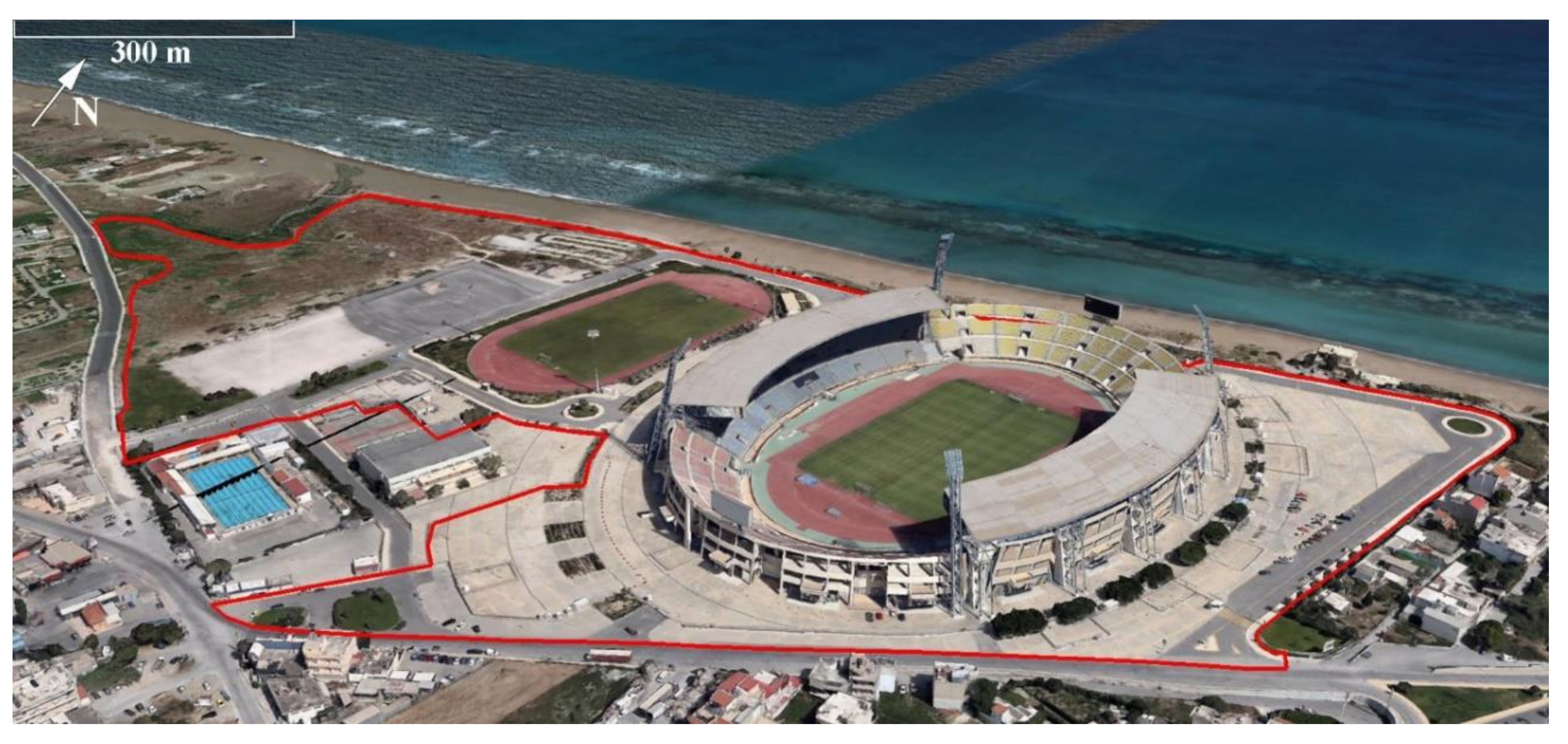
2.1. The Pancretan Stadium
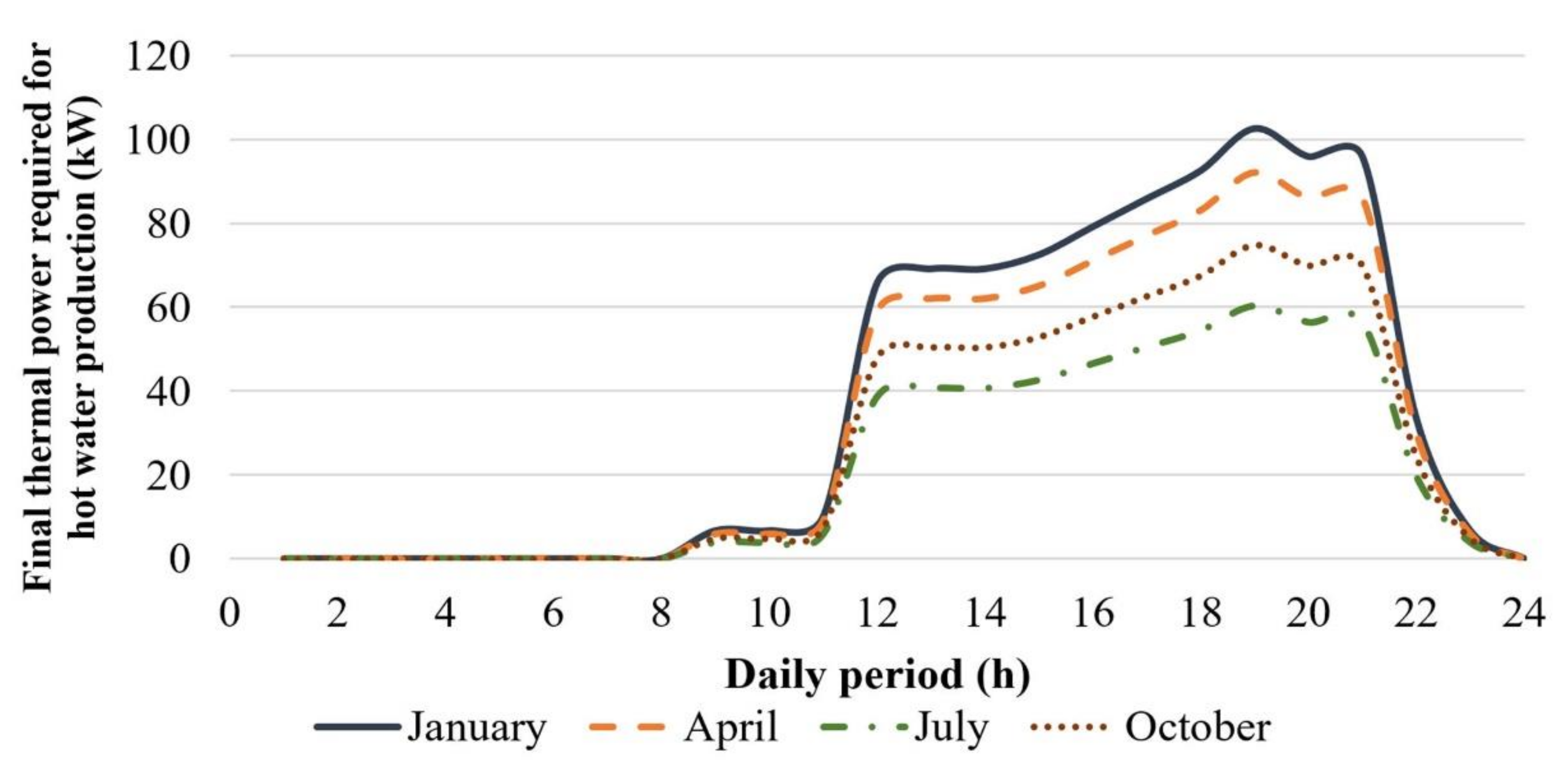
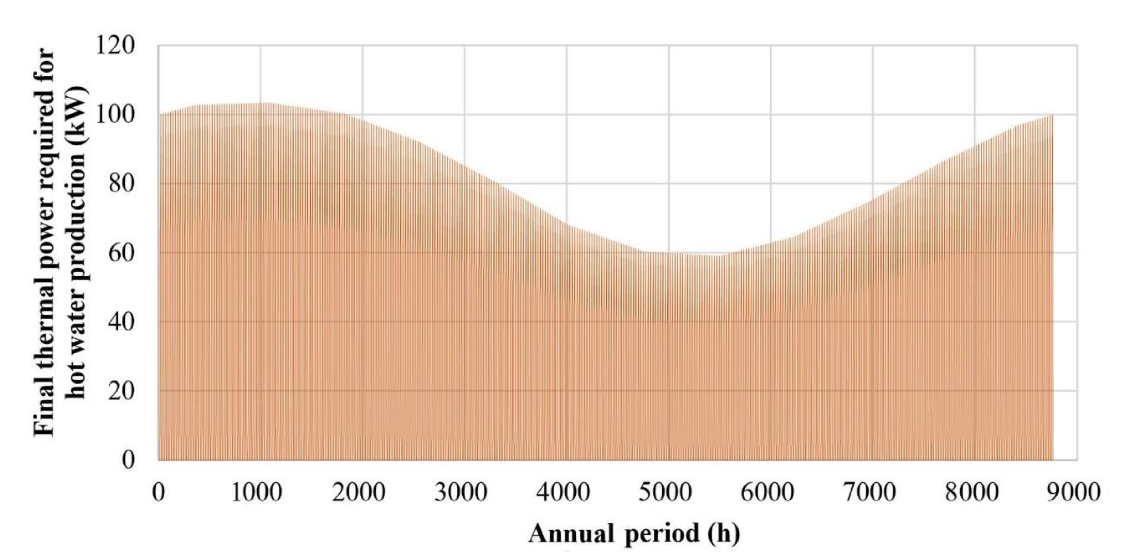
2.2. Existing Thermal Energy Consumption for Hot Water Production
- The stadium’s facilities are used by 900 users daily; half of them make use of the changing rooms and consume 20 L of hot water.
- The daily swimming pools users are estimated at 500; each one of them consumes 30 L of hot water.
- Adopted hot water properties: temperature Thw = 45 °C, density ρhw = 990 kg/m3 and specific heat capacity 4.180 J/kg∙K.
- A 24-h thermal power demand profile is developed by applying the following relationship on hourly basis:
| : | the thermal power required for hot water production (in kW); |
| : | the consumed hot water mass flow rate, equal to the product of the users’ number per hour with the hot water mass consumption per user (in kg/s); |
| Tws: | the water temperature in the water supply network. |
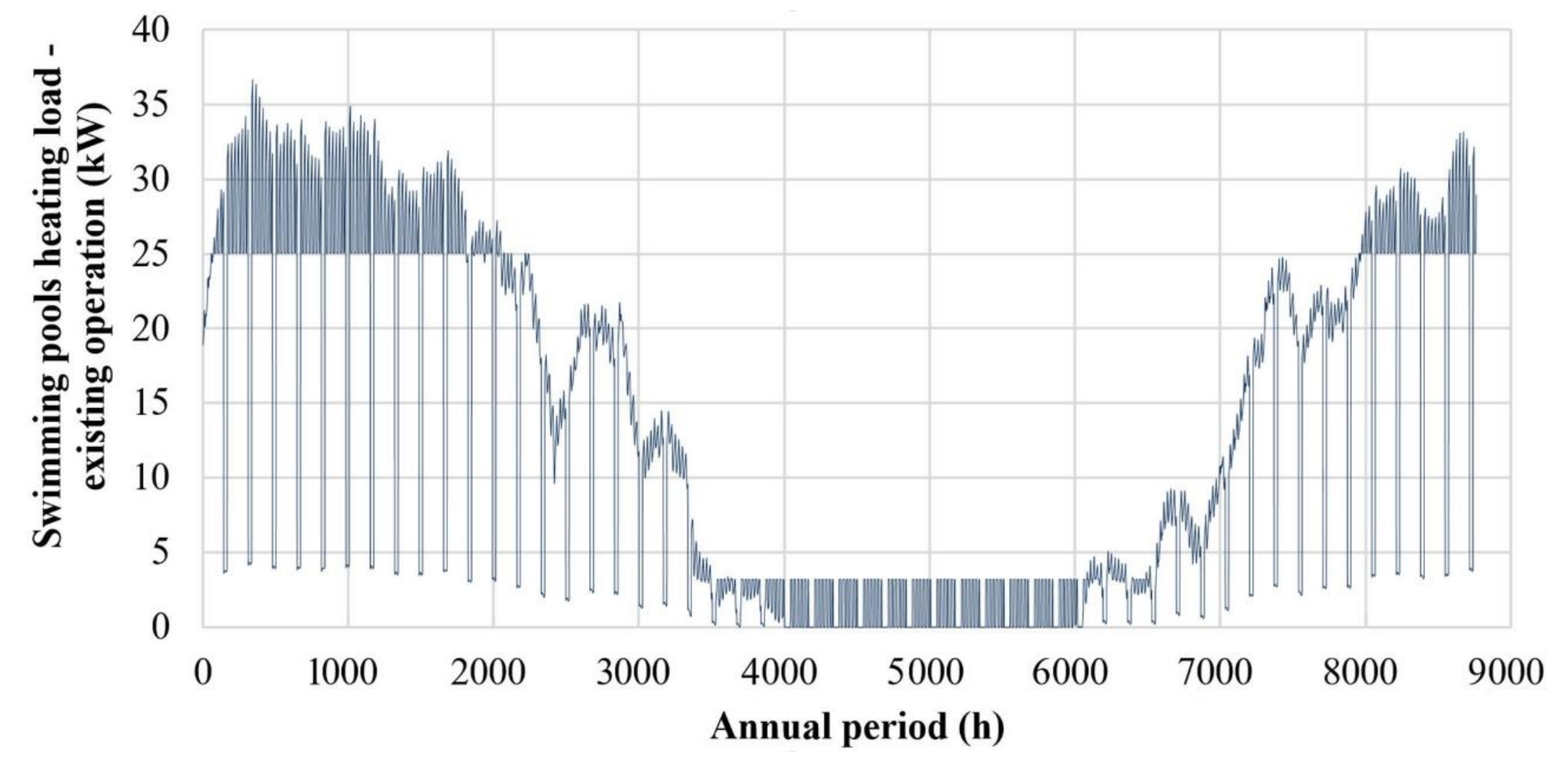
2.3. Existing Thermal Energy Consumption for Swimming Pools Heating
- Temperature: 18 °C in winter and 25 °C in summer;
- Relative humidity: 50%;
- Required ventilation: 33.75 m3 of fresh air per hour and m2 of indoor covered space.
| Asp: | the swimming pools upper surface (in m2); |
| U: | the U-factor determining the heat losses rate from the swimming pools’ surface to the indoor environment (in W/m2∙K); |
| Tw: | the water temperature in the swimming pools (see Table 2). |
2.4. Existing Primary Energy Consumption
- The chemical energy contained in the consumed diesel oil with a factor of 1.1;
- The electricity consumption with a factor of 2.9, in case it is produced by thermal power plants.
3. Solar-Combi Systems
- Performance evaluation, comparing computational and experimental results [48];
4. Application in the Pancretan Stadium
4.1. Climate Conditions—RES Potential
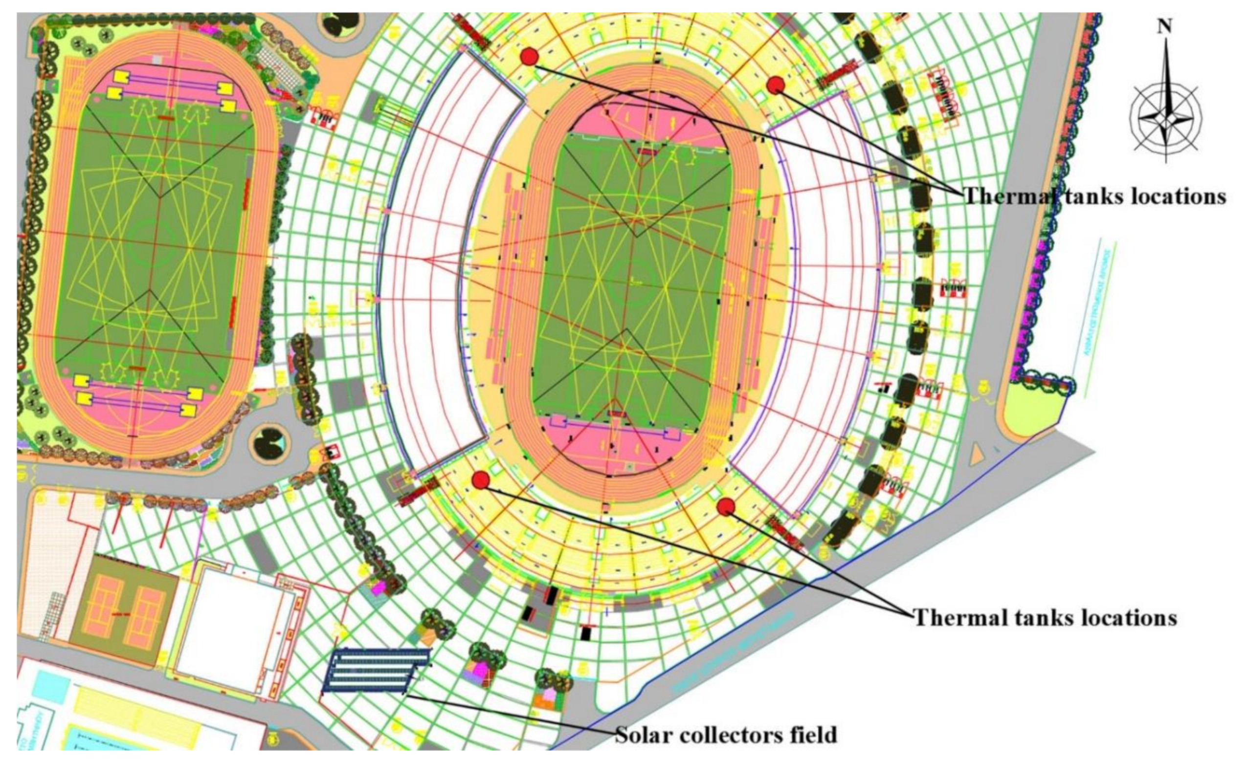
4.2. Existing Infrastructure—Siting Parameters
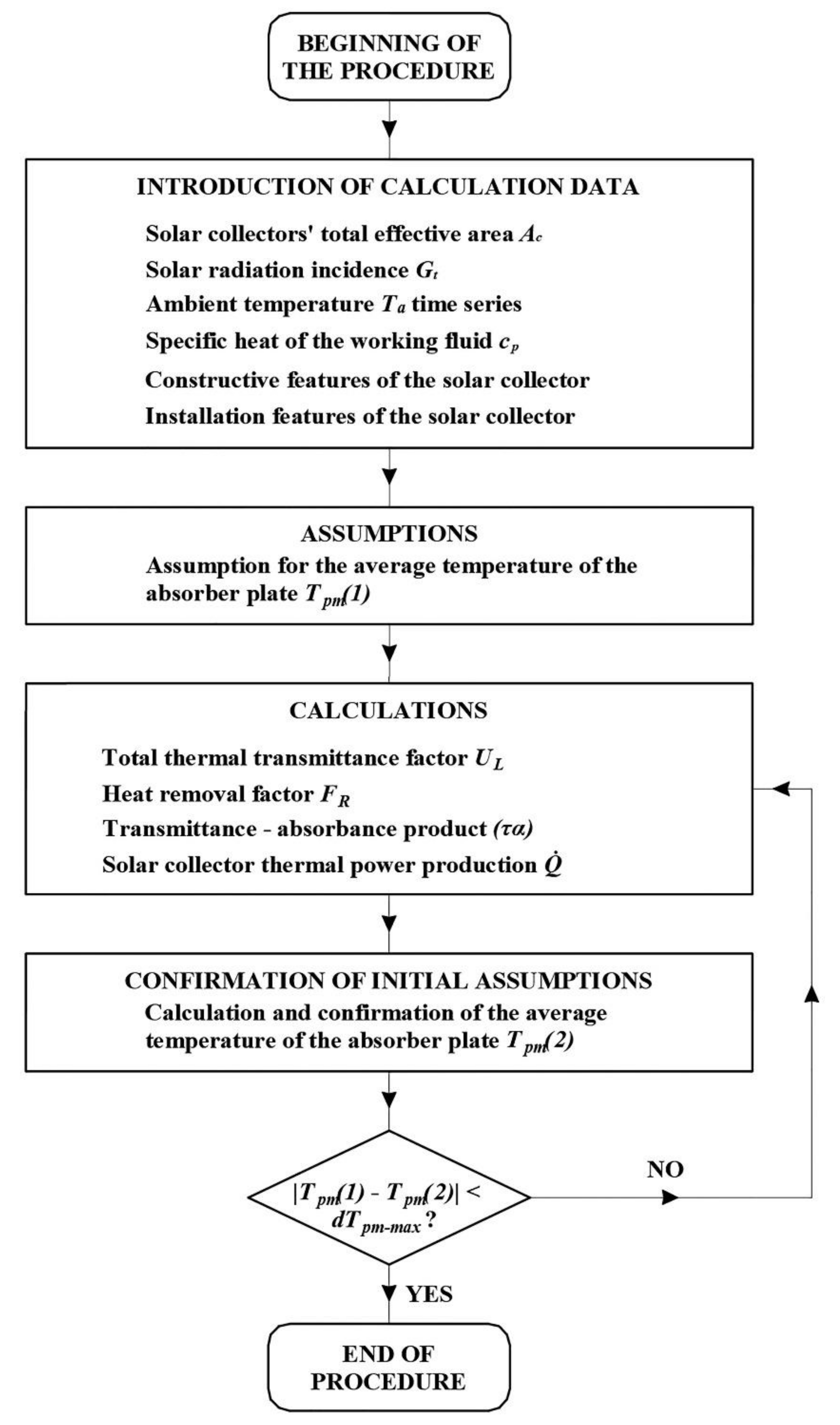
4.3. Mathematical Background—Calculation Process—Dimensioning Methodology
- The solar collector’s effective area: Ac = 2.3 m2.
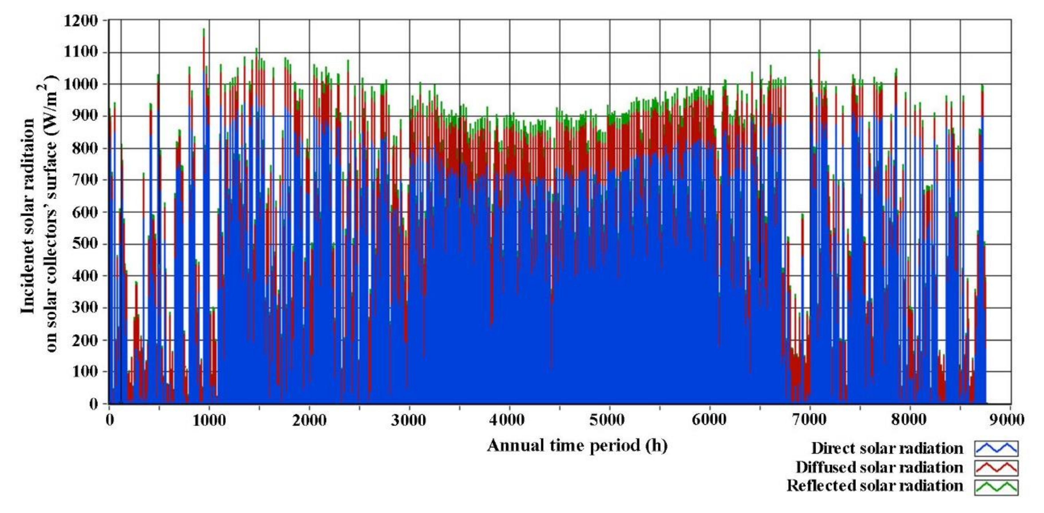
- The total incident solar radiation Gt in W/m2 on the collector’s surface (sum of the direct, diffused and reflected solar radiation), presented in Figure 12.
- The ambient temperature Ta, presented in Figure 9.
- The specific heat capacity of the working fluid cp in kJ/(kg∙K), practically assumed equal to that of pure water (4.184 kJ/kg∙K), in case of water—glycol solution.
- Constructive features and properties of the solar collector:
- -
- the number of the collector’s top covers: N = 1;
- -
- the collector’s insulation thickness te and tb in the side edges and in the bottom respectively: te = tb = 7 mm;
- -
- -
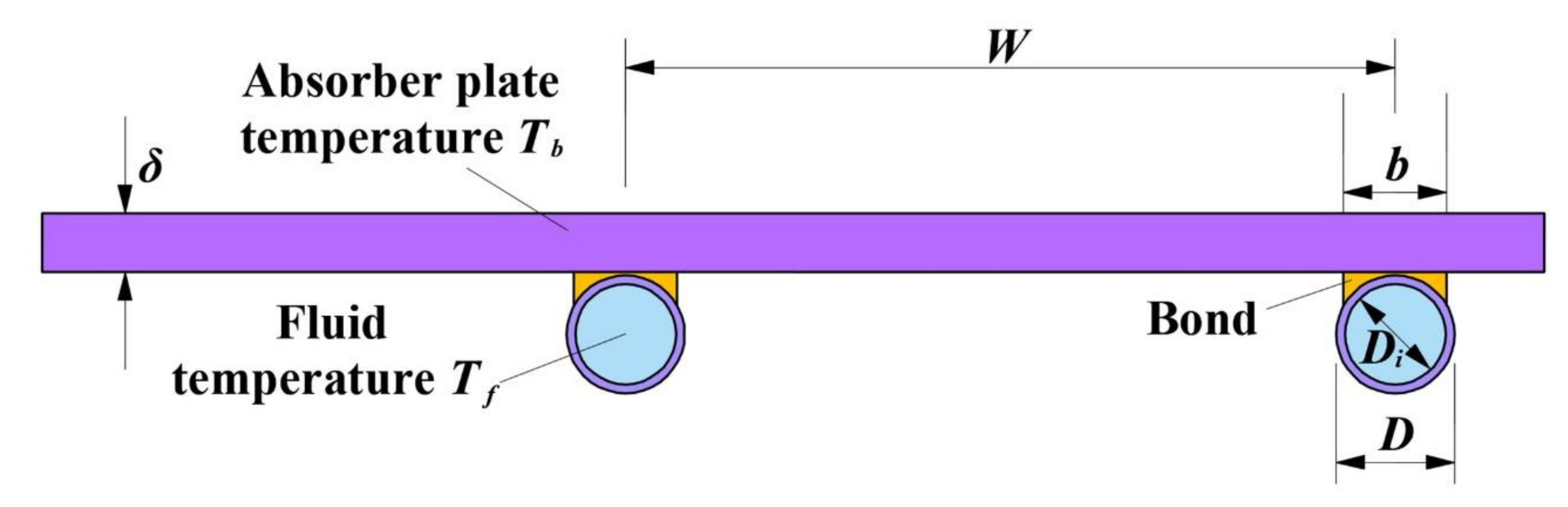
- the collector’s pipeline outer and inner diameter: D = 11 mm and Di = 10 mm respectively;
- -
- the thermal conductivity factors of the collector’s insulation ke and kb for the side edges and the bottom respectively: ke = kb = 0.0245 W/(m∙K);
- -
- the emissivity εg of the collector’s transparent cover: εg = 0.88;
- -
- the emissivity εp of the collector’s absorber plate: εp = 0.95;
- -
- the thermal conductivity factor k of the absorber plate: k = 350 W/(m∙K);
- -
- -
- the thermal conductivity factor kb of the bond’s material between the collector’s pipelines and the absorber plate: kb = 1000 W/(m∙K) (see Figure 14);
- -
- the bond’s thickness b between the collector’s pipelines and the absorber plate: b = 0.60 mm;
- -
- the bond’s width γ between the collector’s pipelines and the absorber plate: γ = 0.120 mm.
- Data regarding the particular collector’s installation, such as:
- -
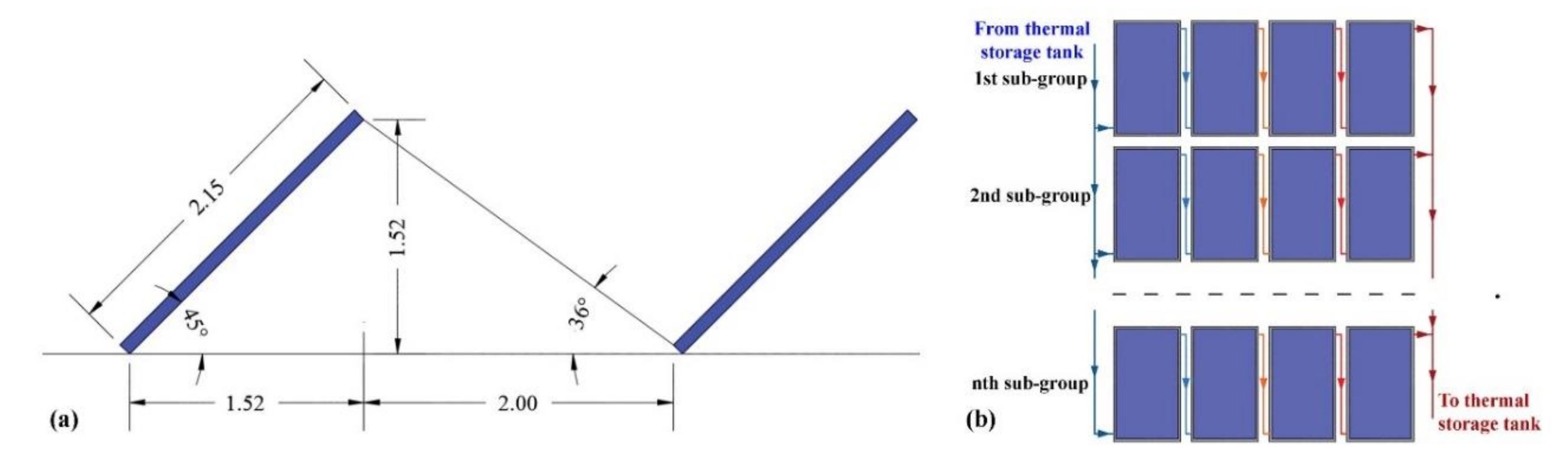
- the collector’s installation angle β in degrees: β = 45°;
- -
- the thermal convective factor hfi for the heat transfer from the absorber plate to the working fluid in the collectors’ pipelines: hfi = 3000 W/(m2∙K);
- -
- the thermal transition factors he and hb for the heat losses from the collector’s side edges and bottom respectively to the ambient: he = hb = 10 W/(m2∙K);
- -
- the mass flow rate of the working fluid in the collector’s pipelines: kg/s∙m2 of solar collector’s surface.
- σ is the Stefan–Boltzam constant (see the nomenclature Table);
- the parameter C is calculated with the following empirical relationship, versus the collector’s installation angle β (in degrees) [56]:
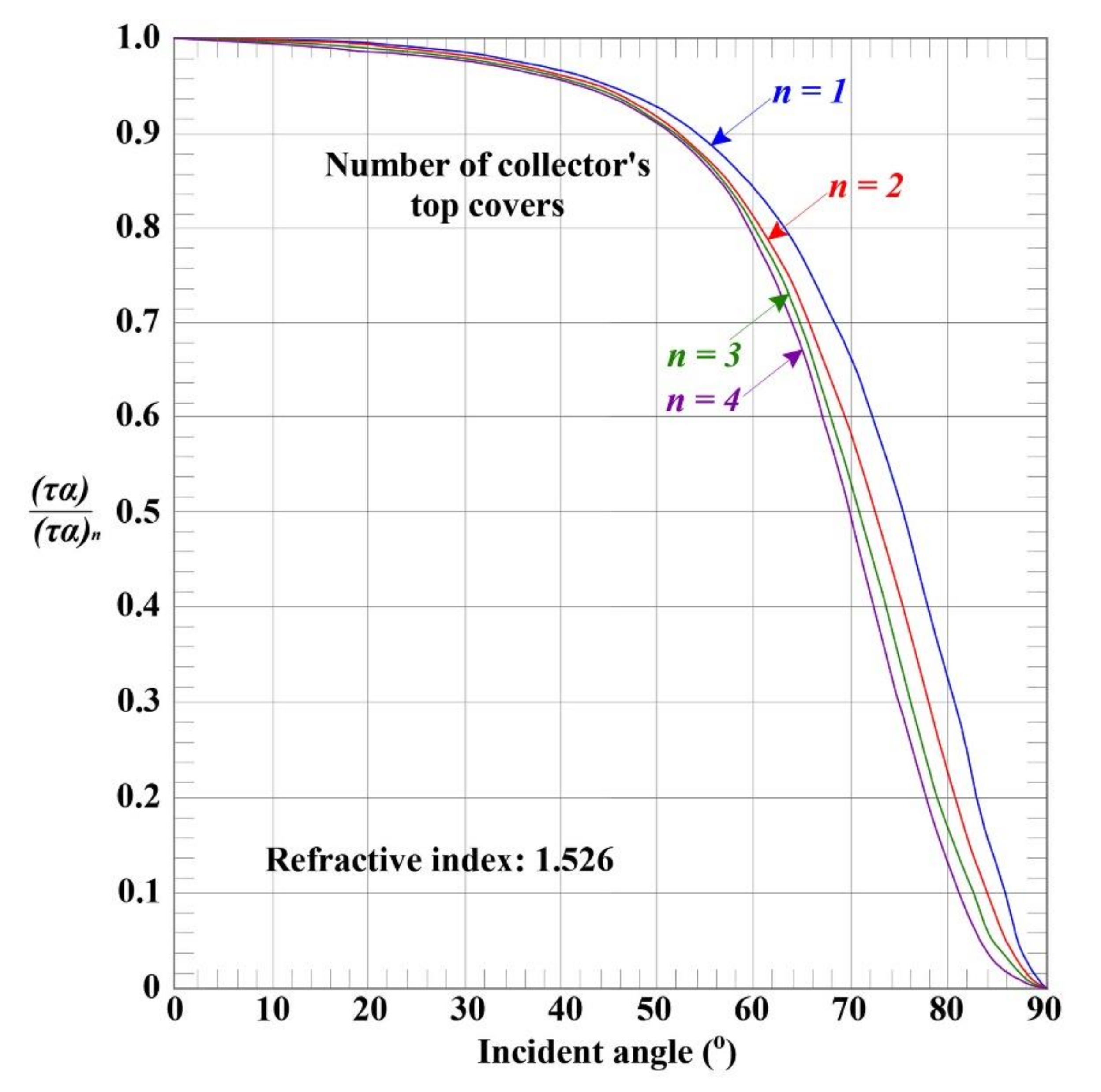
- the parameter f is given by the following empirical relationship, versus the number Ν of the collector’s transparent top covers, the absorber plate emissivity εp and the thermal transition factor ht for the heat losses from the collector to the ambient [56]:
- the parameter e is given by the following empirical relationship versus the average temperature of the absorber plate Tpm (in K) [56]:
4.4. Swimming Pools Heating Load with the Introduction of Passive Measures
5. Results
- Selective coating, flat plate solar collector procurement price: 400 EUR/collector;
- Biomass pellets heat capacity: 5.2 kWh/kg;
- Biomass heater efficiency: 85%;
- Heating distribution system efficiency: 95%;
- Biomass pellets price (in Crete): 350 EUR/tons.
| L.C.: | the annually average, thermal energy production specific cost (in EUR/kWh); |
| I.C.: | the set-up cost of the solar-combi system (in EUR); |
| A.O.C.: | the overall annual operation and maintenance cost (in EUR/year); |
| i: | the discount rate, adopted equal to 3%; |
| L: | the total life period of the solar-combi system, adopted equal to 20 years; |
| n: | the number of the current year of the system’s operation; |
| Eth: | the total annual thermal energy production of the solar-combi system, equal to 315,635 kWh. |
- The calculation of these electricity consumptions would impose a detailed writing down of all the involved hydraulic network with its components, which on the one hand would require considerable amount of additional work and, on the other, is beyond the scope of the present article, which is the dynamic simulation and the dimensioning of the introduced system.
- The contribution of the annual electricity consumption in the circulators and the auxiliary loads would be, more or less, the same, regardless of the dimensioning of the solar-combi system. So, conclusively, it would not affect the optimization of the dimensioning, as there would be an analogous increase in the total L.C. for all the investigated scenarios.
- Finally, this electricity consumption already exists in the current operation state of the heating production system in the examined sports facility. Hence, since the payback period is calculated on the basis of the avoided diesel oil and electricity consumption cost of the current operation, the payback period is not affected by this particular operation cost component.
6. Conclusions
Funding
Acknowledgments
Conflicts of Interest
Nomenclature
| Data | ||
| Symbol | Description | Value |
| cw: | the specific heat capacity of water | 4.180 kJ/kgK |
| Thw: | the hot water temperature | 45 °C |
| Tws: | the water temperature at the hydraulic supply network | see Table 1 |
| ρhw: | density of hot water at 45 °C temperature | 990 kg/m3 |
| Asp: | the swimming pools upper surface area | 25 × 12.5 + 12.5 × 6 = 387.5 m2 |
| Tin: | the swimming pools indoor space temperature according to thermal comfort conditions | in winter: 18 °C in summer: 25 °C |
| Tw: | the desirable water temperature in the swimming pools | main pool: 26 °C training pool: 30 °C |
| hc: | the convective heat transfer factor for indoor space air flows above horizontal surfaces | 2.5 W/m2∙K |
| σ: | the Stefan–Boltzman constant | 5.67 10−8 W/m2∙K4 |
| εw: | the radiation emissivity of water | 0.957 |
| Ac: | the solar collector’s effective area | 2.3 m2 |
| Ta: | the ambient temperature (in K) | see Figure 9 |
| cp: | the specific heat capacity of the working fluid in the solar collectors loop | 4.184 kJ/(kg∙K) |
| N: | the number of the collectors’ protective transparent top cover | 1 |
| te, tb: | the insulation thickness te and tb in the side edges and in the bottom of the solar collectors respectively | 7 mm |
| W: | the distance between two consecutive pipelines of the solar collector | 115 mm |
| D: | the solar collector’s pipeline outer diameter | 11 mm |
| Di: | the solar collector’s pipeline inner diameter | 10 mm |
| ke, kb: | the thermal conductivity factors of the collector’s insulation for the side edges and for the bottom of the collector respectively | 0.0245 W/(m∙K) |
| εg: | the emissivity of the collector’s transparent cover | 0.88 |
| εp: | the emissivity of the collector’s absorber plate | 0.95 |
| k: | the thermal conductivity factor of the absorber plate | 350 W/(m∙K) |
| δ: | the thickness of the absorber plate | 0.50 mm |
| kb: | the thermal conductivity factor of the bond’s material of the collector’s pipelines with the absorber plate | 1000 W/(m∙K) |
| b: | the bond’s thickness of the collector’s pipelines with the absorber plate | 0.60 mm |
| γ: | the bond’s width of the collector’s pipelines with the absorber plate | 0.120 mm |
| β: | the collector’s installation angle | 45° |
| hfi: | the thermal convective factor for the heat transfer from the plate to the working fluid in the collectors’ pipelines | 3000 W/(m2∙K) |
| he, hb: | the thermal transition factors for the heat transfer from the collector’s side edges and bottom respectively to the ambient | 10 W/(m2∙K) |
| : | the mass flow rate of the working fluid inside the collector per unit of solar collectors’ effective surface. | 0.02 kg/s∙m2 |
| m: | the water mass in the storage tank | 5000 kg |
| Us: | the thermal transmittance factor of the thermal storage tank | 0.16 |
| As: | the heat transfer area of the thermal storage tank | 10.9 m2 |
| hw: | the convective heat transfer factor of still water | 50 W/(m2∙K) |
| kc: | the floating insulating cover conductivity coefficient | 0.025 W/(m∙K) |
| dc: | the floating insulating cover thickness | 2.0 cm |
| εc: | the radiation emissivity of the insulating floating cover material | 0.550 |
| t: | the duration of the calculation time step | 3600 s |
| i: | the discount rate | 3% |
| L: | the total life period of the solar-combi system | 20 years |
| Results | ||
| Symbol | Description | |
| : | the hourly average thermal power required for hot water production (in W) | |
| : | the swimming pools hourly average heating load (in W) | |
| : | the total thermal power production by each independent solar-combi system (in W) | |
| : | the total thermal power demand (in W) | |
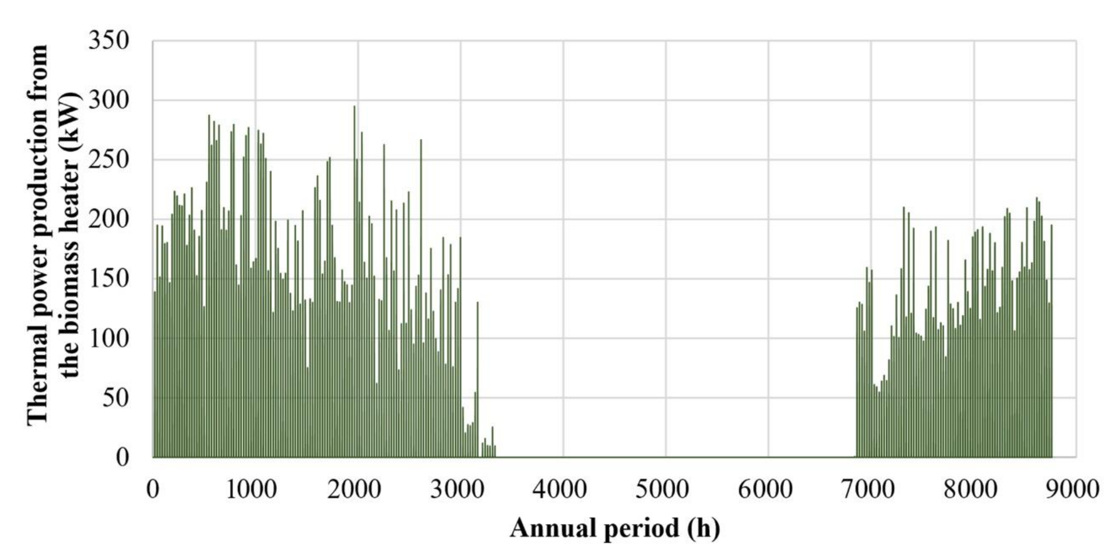
| : | the thermal power production from the biomass heater (in W) | |
| Gt: | the total incident solar radiation (in W/m2) | |
| : | the hourly average consumed hot water mass flow rate (in kg/s) | |
| U: | the U-factor determining the heat transfer rate from the swimming pools free surface to the indoor environment (in W/m2K) | |
| UL: | the total thermal transmittance factor for the heat losses from solar collectors to the ambient (in W/m2K) | |
| Ub, Ue, Ut: | the thermal transmittance factors describing the heat losses from the solar collector’s bottom, side edges and top respectively to the ambient (in W/m2K) | |
| hrw: | the heat transfer factor with radiation from the pools free surface (in W/m2K) | |
| ht: | the thermal transition factor for the heat transfer from the collector to the ambient (in W/m2K) | |
| Tout: | the working medium’s outlet temperature of each solar-combi system (in K) | |
| Ts(i): | the water temperature inside the thermal storage tank at the calculation time step i (in K) | |
| Tpm: | the solar collectors’ absorber plate average temperature (in K) | |
| Tfi: | the fluid’s inlet temperature in the solar collector (in K) | |
| L.C.: | the annually average, thermal energy production specific cost of the solar-combi system (in EUR/kWh) | |
| I.C.: | the initial cost (set-up cost) of the solar-combi system (in EUR) | |
| A.O.C.: | the total annual operation and maintenance cost of the solar-combi system (in EUR/year) | |
References
- Cunio, L.N.; Sproul, A.B. Performance characterisation and energy savings of uncovered swimming pool solar collectors under reduced flow rate conditions. Sol. Energy 2012, 86, 1511–1517. [Google Scholar] [CrossRef]
- Bunea, M.; Perers, B.; Eicher, S.; Hildbrand, C.; Bony, J.; Citherlet, S. Mathematical modelling of unglazed solar collectors under extreme operating conditions. Sol. Energy 2015, 118, 547–561. [Google Scholar] [CrossRef]
- Soltau, H. Testing the thermal performance of uncovered solar collectors. Sol. Energy 1992, 49, 263–272. [Google Scholar] [CrossRef]
- Hashim, W.M.; Shomran, A.T.; Jurmut, H.A.; Gaaz, T.S.; Al-Amiery, A.A. Case study on solar water heating for flat plate collector. Case Stud. Therm. Eng. 2018, 12, 666–671. [Google Scholar] [CrossRef]
- Pandey, K.M.; Chaurasiya, R. A review on analysis and development of solar flat plate collector. Renew. Sustain. Energy Rev. 2017, 67, 641–650. [Google Scholar] [CrossRef]
- Hao, W.; Lu, Y.; Lai, Y.; Yu, H.; Lyu, M. Research on operation strategy and performance prediction of flat plate solar collector with dual-function for drying agricultural products. Renew. Energy 2018, 127, 685–696. [Google Scholar] [CrossRef]
- Tian, Z.; Perers, B.; Furbo, S.; Fan, J. Thermo-economic optimization of a hybrid solar district heating plant with flat plate collectors and parabolic trough collectors in series. Energy Convers. Manag. 2018, 165, 92–101. [Google Scholar] [CrossRef]
- Nitsas, M.T.; Koronaki, I.P. Experimental and theoretical performance evaluation of evacuated tube collectors under Mediterranean climate conditions. Therm. Sci. Eng. Prog. 2018, 8, 457–469. [Google Scholar] [CrossRef]
- Shafieian, A.; Khiadani, M.; Nosrati, A. A review of latest developments, progress, and applications of heat pipe solar collectors. Renew. Sustain. Energy Rev. 2018, 95, 273–304. [Google Scholar] [CrossRef]
- Daghigh, R.; Shafieian, A. Theoretical and experimental analysis of thermal performance of a solar water heating system with evacuated tube heat pipe collector. Appl. Therm. Eng. 2016, 103, 1219–1227. [Google Scholar] [CrossRef]
- Sabiha, M.A.; Saidur, R.; Mekhilef, S.; Mahian, O. Progress and latest developments of evacuated tube solar collectors. Renew. Sustain. Energy Rev. 2015, 51, 1038–1054. [Google Scholar] [CrossRef]
- Lamnatou, C.; Cristofari, C.; Chemisana, D.; Canaletti, J.L. Building-integrated solar thermal systems based on vacuum-tube technology: Critical factors focusing on life-cycle environmental profile. Renew. Sustain. Energy Rev. 2016, 65, 1199–1215. [Google Scholar] [CrossRef]
- Hassanien, R.; Hassanien, E.; Li, M.; Tang, Y. The evacuated tube solar collector assisted heat pump for heating greenhouses. Energy Build. 2018, 169, 305–318. [Google Scholar] [CrossRef]
- Shafii, M.B.; Mamouri, S.J.; Lotfi, M.M.; Mosleh, H.J. A modified solar desalination system using evacuated tube collector. Desalination 2016, 396, 30–38. [Google Scholar] [CrossRef]
- Tyagi, V.V.; Kaushik, S.C.; Tyagi, S.K. Advancement in solar photovoltaic/thermal (PV/T) hybrid collector technology. Renew. Sustain. Energy Rev. 2012, 16, 1383–1398. [Google Scholar] [CrossRef]
- Abdelrazik, A.S.; Al-Sulaiman, F.A.; Saidur, R.; Ben-Mansour, R. A review on recent development for the design and packaging of hybrid photovoltaic/thermal (PV/T) solar systems. Renew. Sustain. Energy Rev. 2018, 95, 110–129. [Google Scholar] [CrossRef]
- Parvez Mahmud, M.A.; Huda, N.; Farjana, S.H.; Lang, C. Environmental impacts of solar-photovoltaic and solar-thermal systems with life-cycle assessment. Energies 2018, 11, 2346. [Google Scholar] [CrossRef]
- Ruan, Y.; Liu, Q.; Li, Z.; Wu, J. Optimization and analysis of building combined cooling, heating and power (BCHP) plants with chilled ice thermal storage system. Appl. Energy 2016, 179, 738–754. [Google Scholar] [CrossRef]
- Murugan, S.; Horák, B. A review of micro combined heat and power systems for residential applications. Renew. Sustain. Energy Rev. 2016, 64, 144–162. [Google Scholar] [CrossRef]
- Huang, Y.; McIlveen-Wright, D.R.; Rezvani, S.; Huang, M.J.; Wang, Y.D.; Roskilly, A.P.; Hewitt, N.J. Comparative techno-economic analysis of biomass fuelled combined heat and power for commercial buildings. Appl. Energy 2013, 112, 518–525. [Google Scholar] [CrossRef]
- Molavi, J.; McDaniel, J. A Review of the benefits of geothermal heat pump systems in retail buildings. Procedia Eng. 2016, 145, 1135–1143. [Google Scholar] [CrossRef]
- Eicker, U.; Vorschulze, C. Potential of geothermal heat exchangers for office building climatisation. Renew. Energy 2009, 34, 1126–1133. [Google Scholar] [CrossRef]
- Pahud, D.; Belliardi, M.; Caputo, P. Geocooling potential of borehole heat exchangers’ systems applied to low energy office buildings. Renew. Energy 2012, 45, 197–204. [Google Scholar] [CrossRef]
- Moià-Pol, A.; Pujol-Nadal, R.; Martínez-Moll, V.; Hertel, J.D. Retrofit of a solar system in sport center in Mallorca. Energy Procedia 2016, 91, 190–196. [Google Scholar] [CrossRef]
- Artuso, P.; Santiangeli, A. Energy solutions for sports facilities. Int. J. Hydrog. Energy 2008, 33, 3182–3187. [Google Scholar] [CrossRef]
- Zuccari, F.; Santiangeli, A.; Orecchini, F. Energy analysis of swimming pools for sports activities: Cost effective solutions for efficiency improvement. Energy Procedia 2017, 126, 123–130. [Google Scholar] [CrossRef]
- Katsaprakakis, D.A. Comparison of swimming pools alternative passive and active heating systems based on renewable energy sources in Southern Europe. Energy 2015, 81, 738–753. [Google Scholar] [CrossRef]
- Kaci, K.; Merzouk, M.; Kasbadji Merzouk, N.; El Ganaoui, M.; Sami, S.; Djedjig, R. Dynamic simulation of hybrid-solar water heated olympic swimming pool. Energy Procedia 2017, 139, 750–757. [Google Scholar] [CrossRef]
- Starke, A.R.; Cardemil, J.M.; Colle, S. Multi-objective optimization of a solar-assisted heat pump for swimming pool heating using genetic algorithm. Appl. Therm. Eng. 2018, 142, 118–126. [Google Scholar] [CrossRef]
- Barbato, M.; Cirillo, L.; Menditto, L.; Moretti, R.; Nardini, S. Feasibility study of a geothermal energy system for indoor swimming pool in Campi Flegrei area. Therm. Sci. Eng. Prog. 2018, 6, 421–425. [Google Scholar] [CrossRef]
- Katsaprakakis, D.A.; Dakanali, I.; Zidianakis, G.; Yiannakoudakis, Y.; Psarras, N.; Kanouras, S. Potential on energy performance upgrade of national stadiums: a case study for the Pancretan stadium, Crete, Greece. Appl. Sci. 2019, 9, 1544. [Google Scholar] [CrossRef]
- Directive on Buildings’ Energy Performance. Official Governmental Gazette 2367B’/12-7-2017. Available online: http://tdm.tee.gr/wp-content/uploads/2017/07/fek_12_7_2017_egrisi_kenak.pdf (accessed on 21 February 2020).
- 2009 ASHRAE Handbook—Fundamentals (SI Edition); American Society of Heating, Refrigerating and Air-Conditioning Engineers, Inc.: Atlanta, GA, USA, 2009.
- Kreider, J.; Rabl, A.; Curtiss, P. Heating and Cooling of Buildings, 3rd ed.; CRC Press: Boca Raton, FL, USA, 2017. [Google Scholar]
- Katsaprakakis, D.A.; Zidianakis, G. Optimized dimensioning and operation automation for a solar-combi system for indoor space heating. A case study for a school building in Crete. Energies 2019, 12, 177. [Google Scholar] [CrossRef]
- Kefalloniti, I.; Ampatzi, E. Building integration of domestic solar combi-systems: The importance of managing the distribution pipework. Energy Build. 2017, 142, 179–190. [Google Scholar] [CrossRef]
- Glembin, J.; Haselhorst, T.; Steinweg, J.; Rockendorf, G. Simulation and evaluation of solar thermal combi systems with direct integration of solar heat into the space heating loop. Energy Procedia 2016, 91, 450–459. [Google Scholar] [CrossRef]
- Antoniadis, C.N.; Martinopoulos, G. Simulation of solar thermal systems with seasonal storage operation for residential scale applications. Procedia Environ. Sci. 2017, 38, 405–412. [Google Scholar] [CrossRef]
- Yang, Z.; Wang, Y.; Li, X. Building space heating with a solar-assisted heat pump using roof-integrated solar collectors. Energies 2011, 4, 504–516. [Google Scholar] [CrossRef]
- Kalder, J.; Annuk, A.; Allik, A.; Kokin, E. Increasing solar energy usage for dwelling heating, using solar collectors and medium sized vacuum insulated storage tank. Energies 2018, 11, 1832. [Google Scholar] [CrossRef]
- Katsaprakakis, D.A.; Zidianakis, G. Upgrading energy efficiency for school buildings in Greece. Procedia Environ. Sci. 2017, 38, 248–255. [Google Scholar] [CrossRef]
- Kyriaki, E.; Giama, E.; Papadopoulou, A.; Drosou, V.; Papadopoulos, A.M. Energy and environmental performance of solar thermal systems in hotel buildings. Procedia Environ. Sci. 2017, 38, 36–43. [Google Scholar] [CrossRef]
- Calise, F.; Figaj, R.D.; Vanoli, L. Energy and economic analysis of energy savings measures in a swimming pool centre by means of dynamic simulations. Energies 2018, 11, 2182. [Google Scholar] [CrossRef]
- Hsieh, S.; Omu, A.; Orehounig, K. Comparison of solar thermal systems with storage: From building to neighbourhood scale. Energy Build. 2017, 152, 359–372. [Google Scholar] [CrossRef]
- Tirumala, N.; Kumar, U.; Martin, A.R. Co-production performance evaluation of a novel solar combi system for simultaneous pure water and hot water supply in urban households of UAE. Energies 2017, 10, 481. [Google Scholar]
- Bois, J.; Mora, L.; Wurtz, E. Energy saving analysis of a solar combi-system using detailed control algorithm modeled with modelica. Energy Procedia 2015, 78, 1985–1990. [Google Scholar] [CrossRef]
- Deng, S.; Dai, Y.J.; Wang, R.Z. Performance optimization and analysis of solar combi-system with carbon dioxide heat pump. Sol. Energy 2013, 98, 212–225. [Google Scholar] [CrossRef]
- D’Antoni, M.; Ferruzzi, G.; Bettoni, D.; Fedrizzi, R. Validation of the numerical model of a turnkey solar combi + system. Energy Procedia 2012, 30, 551–561. [Google Scholar] [CrossRef]
- Johansen, J.B.; Englmair, G.; Dannemand, M.; Kong, W.; Furbo, S. Laboratory testing of solar combi system with compact long term PCM heat storage. Energy Procedia 2016, 91, 330–337. [Google Scholar] [CrossRef]
- Englmair, G.; Dannemand, M.; Johansen, J.B.; Kong, W.; Dragsted, J.; Furbo, S.; Fan, J. Testing of PCM heat storage modules with solar collectors as heat source. Energy Procedia 2016, 91, 138–144. [Google Scholar] [CrossRef]
- Colclough, S.; McGrath, T. Net energy analysis of a solar combi system with seasonal thermal energy store. Appl. Energy 2015, 147, 611–616. [Google Scholar] [CrossRef]
- Ma, Z.; Bao, H.; Roskilly, A.P. Feasibility study of seasonal solar thermal energy storage in domestic dwellings in the UK. Sol. Energy 2018, 162, 489–499. [Google Scholar] [CrossRef]
- Andersen, E.; Furbo, S. Theoretical variations of the thermal performance of different solar collectors and solar combi systems as function of the varying yearly weather conditions in Denmark. Sol. Energy 2009, 83, 552–565. [Google Scholar] [CrossRef]
- Mauthner, F.; Weiss, W.; Spörk-Dür, M. Solar Heat Worldwide: Markets and Contribution to the Energy Supply 2014. AEE-Institute for Sustainable Technologies, A-8200 Gleisdorf, Austria. IEA Solar Heating & Cooling Programme, May 2016. Available online: http://www.iea-shc.org/data/sites/1/publications/solar-heat-worldwide-2016.pdf (accessed on 21 February 2020).
- Wikipedia: Tichelmann-System. Available online: https://de.wikipedia.org/wiki/Tichelmann-System (accessed on 21 February 2020).
- Duffie, J.A.; Beckman, W.A. Solar Engineering of Thermal Processes, 4th ed.; Wiley: Hoboken, NJ, USA, 2017. [Google Scholar]


| Month | Water Temperature in Supply Network (°C) | Monthly Final Thermal Energy Consumption (kWh) | Month | Water Temperature in Supply Network (°C) | Monthly Final Thermal Energy Consumption (kWh) |
|---|---|---|---|---|---|
| 1 | 13 | 27,670 | 7 | 26.2 | 16,256 |
| 2 | 12.8 | 25,149 | 8 | 26.6 | 15,910 |
| 3 | 13.8 | 26,978 | 9 | 24.9 | 16,819 |
| 4 | 16.3 | 24,016 | 10 | 21.7 | 20,147 |
| 5 | 19.9 | 21,704 | 11 | 18.1 | 22,509 |
| 6 | 23.8 | 17,740 | 12 | 14.8 | 26,113 |
| Parameter | Value |
|---|---|
| Radiation emissivity of water εw | 0.957 |
| Radiation emissivity of the insulating floating cover material εc | 0.550 |
| Convective coefficient hc for heat transfer from horizontal indoor surface to the indoor space (W/m2∙K) [33,34] | 2.5 |
| Convective coefficient hw of standing still water (W/m2∙K) [33,34] | 50.0 |
| Insulating cover thickness dc (cm) | 2.0 |
| Insulating cover conductivity coefficient kc (W/m∙K) | 0.025 |
| Main swimming pool’s upper surface dimensions (m2) | 25 12.5 = 312.5 |
| Training swimming pool’s upper surface dimensions (m2) | 12.5 6 = 75 |
| Desirable water temperature Tw of the main / training swimming pool (°C) | 26/30 |
| Daily operation schedule (Monday—Friday) | 14:00–22:00 |
| Saturday operation schedule | 9:00–14:00 |
| Heating Load | Hot Water Production | Swimming Pools Heating | Total | |
|---|---|---|---|---|
| Thermal energy demand (kWh) | 261,015 | 112,216 | 373,231 | |
| Thermal energy production (kWh) | Diesel oil | 128,550 | 0 | 128,550 |
| Electricity | 132,465 | 112,216 | 244,681 | |
| Energy source consumption | Diesel oil (L) | 16,500 | 0 | 16,500 |
| Electricity (kWh) | 139,436 | 52,198 | 191,634 | |
| Primary energy consumption (kWh) | Diesel oil | 186,059 | 0 | 186,059 |
| Electricity | 404,366 | 151,373 | 555,739 | |
| Total | 590,425 | 151,373 | 741,798 | |
| Energy Source/Use | Consumption | Procurement Price | Total Procurement Cost (EUR) |
|---|---|---|---|
| Diesel oil/hot water production | 16,500 L | 1 EUR/L | 16,500 |
| Electricity/hot water production | 139,436 kWh | 0.1729 EUR/kWh | 24,108 |
| Electricity/swimming pools heating | 52,198 kWh | 0.1729 UR/kWh | 9025 |
| Existing energy resources total procurement cost (EUR) | 49,634 | ||
| Solar Radiation | Installation Angle | ||||||
|---|---|---|---|---|---|---|---|
| 20° | 30° | 35° | 40° | 45° | 50° | 60° | |
| Annual incident solar irradiation (kWh/m2) | |||||||
| Direct | 1408 | 1453 | 1459 | 1454 | 1438 | 1411 | 1325 |
| Diffused | 630 | 607 | 592 | 574 | 555 | 534 | 488 |
| Reflected | 19 | 43 | 58 | 75 | 94 | 115 | 161 |
| Total | 2057 | 2103 | 2109 | 2103 | 2087 | 2060 | 1974 |
| Incident solar irradiation during winter—from 15/10 to 15/3 (kWh/m2) | |||||||
| Direct | 492 | 545 | 565 | 581 | 592 | 599 | 599 |
| Diffused | 168 | 161 | 157 | 153 | 148 | 142 | 130 |
| Reflected | 5 | 12 | 16 | 21 | 26 | 32 | 45 |
| Total | 665 | 718 | 738 | 755 | 766 | 775 | 774 |
| Scenario Number | 1 | 2 | 3 | 4 | 5 |
|---|---|---|---|---|---|
| System’s Component | Procurement and Installation Cost (EUR) | ||||
| Biomas heater 150,000 kcal/h | 25,000 | ||||
| Cyclonic filter | 10,000 | ||||
| Electrical panel | 3000 | ||||
| Biomass tank 8 m3 | 5000 | ||||
| Four thermal tanks 5000 L each | 32,000 | ||||
| Copper pipelines with insulations | 60,000 | ||||
| Expansion vessels | 2000 | ||||
| Circulators | 5000 | ||||
| Swimming pools insulation cover | 10,000 | ||||
| Solar collectors | 38,400 | 44,800 | 51,200 | 57,600 | 64,000 |
| Total set-up cost | 190,400 | 196,800 | 203,200 | 209,600 | 216,000 |
| Investigating Scenario | 1 | 2 | 3 | 4 | 5 |
|---|---|---|---|---|---|
| Solar collectors number | 96 | 112 | 128 | 144 | 160 |
| Solar collectors’ initial thermal energy production (kWh) | 146,677 | 169,816 | 192,948 | 216,081 | 239,214 |
| Solar collectors’ thermal energy storage (kWh) | 144,183 | 161,039 | 174,799 | 186,648 | 198,495 |
| Solar collectors’ thermal energy surplus (kWh) | 2494 | 8777 | 18,149 | 29,433 | 40,719 |
| Biomass thermal energy production (kWh) | 171,452 | 154,596 | 140,836 | 128,987 | 117,140 |
| Solar collectors’ annual penetration percentage (%) | 45.68 | 51.02 | 55.38 | 59.13 | 62.89 |
| Solar collectors’ annual thermal energy surplus percentage (%) | 0.79 | 2.78 | 5.75 | 9.33 | 12.90 |
| Biomass pellets annual consumption (tons) | 40.83 | 36.82 | 33.54 | 30.72 | 27.90 |
| Biomass pellets annual procurement cost (EUR) | 14,291 | 12,886 | 11,739 | 10,751 | 9764 |
| Annual, net monetary saving (EUR) | 35,342 | 36,747 | 37,894 | 38,882 | 39,870 |
| Investment’s payback period (years) | 5.39 | 5.36 | 5.36 | 5.39 | 5.42 |
| Thermal energy specific production cost (EUR/kWh) | 0.0650 | 0.0627 | 0.0610 | 0.0597 | 0.0584 |
| Heating Load | Hot Water Production | Swimming Pools Heating | Total | |
|---|---|---|---|---|
| Thermal energy demand (kWh) | 261,015 | 54,620 | 315,635 | |
| Thermal energy production (kWh) | Solar collectors | 169,700 | 5099 | 174,799 |
| Biomass | 91,315 | 49,521 | 140,836 | |
| Biomass consumption (tons) | 20.609 | 10.588 | 31.197 | |
| Primary energy consumption (kWh) | 119,365 | 61,326 | 180,691 | |
© 2020 by the author. Licensee MDPI, Basel, Switzerland. This article is an open access article distributed under the terms and conditions of the Creative Commons Attribution (CC BY) license (http://creativecommons.org/licenses/by/4.0/).
Share and Cite
Katsaprakakis, D.A. Computational Simulation and Dimensioning of Solar-Combi Systems for Large-Size Sports Facilities: A Case Study for the Pancretan Stadium, Crete, Greece. Energies 2020, 13, 2285. https://doi.org/10.3390/en13092285
Katsaprakakis DA. Computational Simulation and Dimensioning of Solar-Combi Systems for Large-Size Sports Facilities: A Case Study for the Pancretan Stadium, Crete, Greece. Energies. 2020; 13(9):2285. https://doi.org/10.3390/en13092285
Chicago/Turabian StyleKatsaprakakis, Dimitris Al. 2020. "Computational Simulation and Dimensioning of Solar-Combi Systems for Large-Size Sports Facilities: A Case Study for the Pancretan Stadium, Crete, Greece" Energies 13, no. 9: 2285. https://doi.org/10.3390/en13092285
APA StyleKatsaprakakis, D. A. (2020). Computational Simulation and Dimensioning of Solar-Combi Systems for Large-Size Sports Facilities: A Case Study for the Pancretan Stadium, Crete, Greece. Energies, 13(9), 2285. https://doi.org/10.3390/en13092285