Article

Multi-Target Control Strategy of DFIG Using Virtual Synchronous Generator Based on Extended Power Resonance Control under Unbalanced Power Grid

1
College of Electrical Engineering, Zhejiang University, Hangzhou 310027, China
2
State Key Laboratory of Smart Grid Protection and Control, Nanjing 211106, China
3
NARI Group Corporation, Nanjing 211106, China
*
Author to whom correspondence should be addressed.
Energies 2020, 13(9), 2232; https://doi.org/10.3390/en13092232
Submission received: 15 March 2020 / Revised: 23 April 2020 / Accepted: 26 April 2020 / Published: 3 May 2020
(This article belongs to the Special Issue Power Electronics in Renewable Energy Systems Ⅱ)

Abstract

:
Virtual synchronous generator control is considered as an effective solution to optimize the frequency response characteristics of doubly fed induction generator. However, due to the insufficient control bandwidth of the original virtual synchronous generator, it has little control effect over the oscillating components of the power caused by the unbalanced grid voltage. Therefore, long-term unbalanced voltage will cause a series of problems, such as distortion of stator and rotor currents, as well as oscillations of power and electromagnetic torque, which seriously affect the power quality and the operating performance of the doubly fed induction generator. To solve these problems, the concept of extended power is introduced, and the second-order generalized integrator-based resonant controller is used to control the extended power and traditional power. Control targets of the extended power method are discussed and extended, so that the doubly fed induction generator system using extended power resonant control-based virtual synchronous generator control can realize three different control targets under the unbalanced grid condition. The three control targets are: balanced and sinusoidal stator current, sinusoidal stator current and constant active power, and sinusoidal stator current and constant reactive power and electromagnetic torque. The three control targets can also be flexibly switched according to the real-time requirements of the grid with unbalanced voltage. The simulation results verify the effectiveness of the control method.

Graphical Abstract

1. Introduction

With the increase of renewable energy generation, the power electronic characteristics of the power system are more and more obvious [1]. For the widely adopted doubly fed induction generators (DFIG)-based wind power generation, when various vector control (VC) [2] or direct power control (DPC) strategies are used [3,4], the rotor speed of DFIG and the grid frequency are decoupled from each other, so the DFIG system cannot respond to the frequency disturbance of the grid, which will reduce the stability of the power system. In order to improve the equivalent inertia of the grid, virtual synchronous generator (VSG) control has been studied and considered as an effective solution for DFIG [5,6,7,8,9]. The VSG control imitates the operating mechanism of the conventional synchronous generator in order to obtain the same operating characteristics of inertia and frequency support. In VSG control of DFIG, the active power control loop simulates the rotor swing equation of the conventional SG to realize the active power-frequency regulation in order to improve the frequency-response characteristic, and the reactive power control loop simulates the excitation process of the SG to realize the reactive power-voltage regulation. Therefore, the DFIG based on VSG can have the same inertial characteristics as the SG; i.e., the synthetic inertia or virtual inertia can be given to the DFIG by the VSG control. In other words, when the grid frequency is disturbed, the mechanical rotational kinetic energy of the rotor can be used to provide dynamic frequency support for the grid, which completely changes the frequency response capability of the DFIG.
However, since the DFIG system is often installed in the remote or offshore areas, the grid voltage unbalance becomes more and more frequent due to the change of large number of three-phase unbalanced loads. Since the control bandwidth of the original VSG is insufficient, long-term unbalanced voltage will cause problems such as distortion of stator and rotor currents, as well as oscillation of power and torque of the DFIG, which seriously affect its power quality and operation performance [10,11,12,13]. In addition, under unbalanced grid voltage, the requirements of the grid for the power quality index of DFIG are different over time, and these requirements cannot be met at the same time [14,15,16]. Therefore, the control target of the DFIG should be selected according to the priority of different control targets and be able to be switched flexibly.
Many literatures have studied the improved control strategies for the DFIG under unbalanced power grid. A positive and negative sequence rotor currents separation method is proposed in [17,18] using VC strategy, where the positive and negative sequence components are controlled separately in positive and reverse synchronous rotating coordinates. Although the control performance is improved, the complexity of the control system is also greatly increased, and the dynamic performance is deteriorated. The authors of [19] propose a power compensation method for the DFIG under unbalanced grid using modified DPC strategy; on the basis of the original power reference value, the power fluctuation compensation term generated by the negative sequence voltage is added, and multiple targets can be achieved by changing the compensation term. However, a phase sequence separation module is still needed in this method. An extended power method was proposed in [20] for DFIG using the sliding mode DPC under unbalanced grid to achieve only one control target, which is to output constant reactive power and constant electromagnetic torque. In addition, due to the modification of the original active power reference, there are DC steady-state errors in the output active power.
However, there are only a few literatures studying the control strategy for DFIG using VSG control under unbalanced grid voltage. A torque resonator closed-loop compensation term is added to the original VSG in [21]. With the help of the powerful control ability of the resonator, the torque ripple of DFIG is eliminated. However, there are still some research gaps on the improved control strategies of the VSG-controlled DFIG system under unbalanced power grid. Firstly, only one single control target is obtained, so multi-target control strategy is necessary to meet different requirements of the unbalanced grid. Secondly, the phase-locked loop (PLL) is still needed in order to provide the electrical angle required for the coordinate transformation of stator voltage and current, so a simple strategy without PLL or sequence separation, such as the extended power method, is preferred. Moreover, the combination of the simple method with the VSG control need to be further investigated.
In this paper, a novel multi-target control strategy for DFIG using a VSG under unbalanced grid voltage is proposed by introducing the extended power method and resonant controller into the conventional VSG. An extended power control loop is added to the original control structure of VSG as an outer loop in order to compensate the control voltage. By analyzing the extended power in detail, two more control targets are proposed for the extended power control loop in this paper, i.e., balanced and sinusoidal stator current, as well as sinusoidal stator current and constant active power. Therefore, the proposed strategy can simply realize three different control targets without the need of either PLL or sequence separation. Moreover, due to the introduction of the extended power resonant controller, the DC steady-state errors in the output active and reactive power are avoided. In addition, the analysis and design of the extended power control loop is discussed in detail. The simulation results verify that the power quality and control performance of DFIG are improved using the proposed strategy.
The rest of this paper is organized as follows. In Section 2, the basic principle of VSG control for DFIG is introduced briefly. The characteristics of the DFIG under unbalanced grid voltage is analyzed in Section 3. In Section 4, the proposed VSG control based on the extended power resonance control for the DFIG under unbalanced power grid is introduced, and the design process is discussed in detail. In Section 5, the simulation studies are implemented on a 2MW DFIG system. Then, a discussion is provided in Section 6, and finally, the conclusions are drawn.

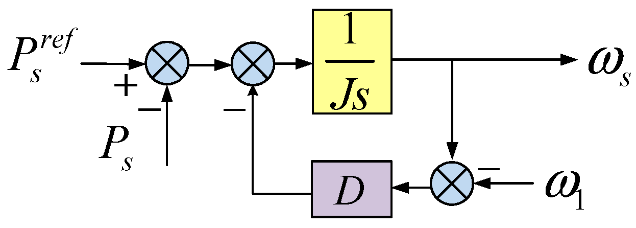
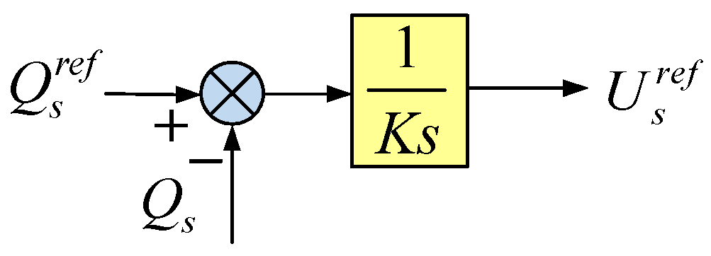
2. Basic Principle of VSG Control for DFIG

The basic idea of the VSG control of DFIG is to increase the equivalent inertia of the DFIG and improve the frequency response characteristics of the system by simulating the rotor motion equation and the excitation process of the traditional SG.
The active power-frequency regulation process of traditional SG can be simulated by the equivalent equation shown in (1).
P s r e f P s D ( ω ω 1 ) = J ω 1 d ω d t
where P s r e f is the reference value of the active power; Ps is the output active power of the DFIG; D is the damping coefficient; J is the virtual inertia; ω1 is the rated angular frequency of the grid, i.e., 100π rad/s and ω is the stator electrical angular frequency generated by VSG. D(ωω1) is used to simulate the damping power generated by the damper windings in the SG to achieve the effect of suppressing frequency oscillation and improving the system stability.
Therefore, the active power-frequency control loop of the VSG can be designed according to (1), which is shown in Figure 1.
The reactive power-voltage regulation process of the traditional SG can be simulated by the equivalent equation shown in (2).
Q s r e f Q s = K d U s d t
where Q s r e f is the reference value of the reactive power, Qs is the output reactive power by DFIG, Us is the amplitude of the stator voltage and K is the excitation adjustment factor.
Therefore, the reactive power-voltage control loop of the VSG can be designed according to (2), as shown in Figure 2.
By using the difference between the stator angular frequency generated by the active power-frequency control loop and the rotor electrical angular frequency obtained by the optical encoder, the slip frequency can be obtained, and the phase information of the rotor excitation voltage can also be calculated through an integral module. The amplitude of the rotor excitation voltage can be obtained through a PI module by using the stator voltage reference value generated by the reactive power-voltage control loop. By using (3) to synthesize the phase information and amplitude information of the rotor excitation voltage, the reference value of the three-phase rotor excitation voltage can be obtained.
{ U r a = U r cos ( θ s l i p ) U r b = U r cos ( θ s l i p 2 3 π ) U r c = U r cos ( θ s l i p 4 3 π )
where Ur is the reference of the rotor excitation voltage, and θslip is the slip angle of the DFIG.
The reference three-phase rotor excitation voltage obtained by (3) can be converted into a two-phase rotor coordinate system, and then, the three-phase switching signal can be generated through a space vector pulse width modulation (SVPWM) module. The block diagram of the VSG control of the DFIG system is shown in Figure 3.
It can be seen from Figure 3 that, during the VSG control of the DFIG, when the frequency disturbance of power grid occurs, the VSG has a relatively slow dynamic response due to the function of the inertia module in the active power-frequency control loop. At this time, the mechanical power input to the DFIG and the electromagnetic power output will have a short time unbalance. This unbalance will change the mechanical rotational speed of the rotor, and the mechanical rotational kinetic energy stored in the rotor will be used to provide frequency support for the power grid.

3. Impact of Unbalanced Grid on DFIG and VSG

When the grid voltage is unbalanced, since the stator of the DFIG is directly connected to the grid, the stator voltage and current vector of the DFIG can be expressed as:
U s s = U s + + e j ω 1 t + U s e j ω 1 t I s s = I s + + e j ω 1 t + I s e j ω 1 t
where U s s and I s s are the stator voltage and current vector of the DFIG in two-phase stationary coordinate system, U s + + and I s + + are the positive sequence components of the stator voltage and current in the forward synchronous rotating coordinate system and U s and I s are the negative sequence components of the stator voltage and the stator current in the reverse synchronous rotating coordinate system. They can be expressed as:
U s + + = U s d + + + j U s q + + U s = U s d + j U s q I s + + = I s d + + + j I s q + + I s = I s d + j I s q
The complex power output from the stator of the DFIG to the grid can be expressed as:
S s = P s + j Q s = 3 2 U s s I ^ s s
where “^” represents the conjugate vector.
Substituting (4) and (5) into (6) yields:
{ P s = P 0 + P 1 cos 2 ω 1 t + P 2 sin 2 ω 1 t Q s = Q 0 + Q 1 cos 2 ω 1 t + Q 2 sin 2 ω 1 t
where P0 and Q0 are the DC components of the active and reactive power, P1 and P2 are the amplitudes of the cosine and sine oscillating components of the active power, Q1 and Q2 are the amplitudes of the cosine and sine oscillating components of the reactive power and
[ P 0 Q 0 P 1 P 2 Q 1 Q 2 ] = 3 2 [ U s d + + U s q + + U s d   U s q U s q + + U s d + + U s q   U s d U s d U s q U s d + + U s q + + U s q U s d U s q + + U s d + + U s q U s d   U s q + + U s d + + U s d U s q U s d + + U s q + + ] [ I s d + + I s q + + I s d I s q ]
It can be seen from Figure 1 and Figure 2 that both the active power-frequency control loop and the reactive power-voltage control loop of the VSG use integral modules, so that they can realize accurate tracking of the two DC components of P0 and Q0. However, the integral modules have little control effect over the four oscillating components of P1cos2ω1t, P2sin2ω1t, Q1cos2ω1t and Q2sin2ω1t.
At this time, the stator and rotor flux linkage of DFIG can be expressed as:
{ ψ s + + = I s + + L s + I r + + L m ψ r + + = I r + + L r + I s + + L m ψ s = I s L s + I r L m ψ r = I r L r + I s L m
where Ψ s + + and Ψ r + + are the positive sequence components of the stator and rotor flux in the forward synchronous rotating coordinate system; Ψ s and Ψ r are the negative sequence components of the stator and rotor flux in the reverse synchronous rotating coordinate system; I r + + and I r are the positive sequence component of the rotor current in the forward synchronous rotating coordinate system and the negative sequence component of the rotor current in the reverse synchronous rotating coordinate system, respectively, and Ls, Lr and Lm are the equivalent inductance of the stator, equivalent inductance of the rotor and the equivalent mutual inductance between the stator and the rotor, respectively.
Ignoring the influence of stator resistance in the steady state, the stator flux of DFIG can be represented by the stator voltage, i.e.,
{ ψ s d + + = U s q + + ω 1 ; ψ s q + + = U s d + + ω 1 ψ s d = U s q ω 1 ; ψ s q = U s d ω 1
Substituting (9) and (10) into (8) gives the relationship between the active and reactive power and the rotor current under the unbalanced grid, i.e.,
[ P 0 Q 0 P 1 P 2 Q 1 Q 2 ] = 3 2 1 ω 1 L s [ 0 U s d + + 2 + U s q + + 2 U s d 2 U s q 2 2 U s q + + U s d 2 U s d + + U s q 2 U s d + + U s d + 2 U s q + + U s q 0 0 ] + 3 2 L m L s [ U s d + + U s q + + U s d   U s q U s q + + U s d + + U s q   U s d U s d U s q U s d + + U s q + + U s q U s d U s q + + U s d + + U s q U s d   U s q + + U s d + + U s d U s q U s d + + U s q + + ] [ I r d + + I r q + + I r d I r q ]
The electromagnetic torque of the DFIG can be expressed as:
T e = P e ω r / p = 3 p 2 ω r Re [ j ω 1 ψ s + I ^ s + + j ( ω 1 ω r ) ψ r + I ^ r + ] = T 0 + T 1 cos 2 ω 1 t + T 2 sin 2 ω 1 t
where T0, T1 and T2 are the DC component of the electromagnetic torque and amplitude of the cosine and sine oscillating components, respectively, and p is the pole pair of the DFIG.
Substituting (9) and (10) into (12) can obtain the relationship between the electromagnetic torque and the rotor current of the DFIG under the unbalanced grid, i.e.,
[ T 0 T 1 T 2 ] = 3 2 L m L s p ω 1 [ U s d + + U s q + + U s d U s q U s d U s q U s d + + U s q + + U s q U s d U s q + + U s d + + ] [ I r d + + I r q + + I r d I r q ]
It can be seen from (11) and (13) that, if the original VSG control is not improved, when the grid voltage is unbalanced, there will be many problems, such as stator and rotor current distortions, active and reactive power fluctuations and torque oscillations. The power quality of the DFIG is difficult to meet the grid requirements.

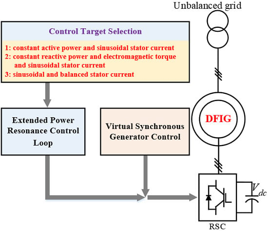
4. Multi-Target Operation Strategies of VSG Control under Unbalanced Grid

4.1. Control Target Analysis

In order to solve the problems of the original VSG control proposed in [9] under the unbalanced power grid, the concept of expended power is introduced in this paper. Define the extended complex power of the DFIG as:
S ˜ s = j P ˜ s + Q ˜ s = 3 2 U ˜ s I ^ s
where P ˜ s is the extended active power output from the stator, Q ˜ s is the extended reactive power output from the stator, U ˜ s is the extended stator voltage vector, which is obtained by delaying the stator voltage vector by 1/4 the fundamental period and
U ˜ s s = U ˜ s + + e j ω 1 t + U ˜ s e j ω 1 t
Substituting (15) into (14), (16) can be obtained.
{ P ˜ s = P ˜ 0 + P ˜ 1 cos 2 ω 1 t + P ˜ 2 sin 2 ω 1 t Q ˜ s = Q ˜ 0 + Q ˜ 1 cos 2 ω 1 t + Q ˜ 2 sin 2 ω 1 t
where P ˜ 0 and Q ˜ 0 are the DC components of the extended active and reactive power, P ˜ 1 and P ˜ 2 are the amplitudes of the cosine and sine oscillating components of the extended active power, Q ˜ 1 and Q ˜ 2 are the amplitudes of the cosine and sine components of the extended reactive power and
[ P ˜ 0 Q ˜ 0 P ˜ 1 P ˜ 2 Q ˜ 1 Q ˜ 2 ] = 3 2 [ U s d + + U s q + + U s d   U s q U s q + + U s d + + U s q   U s d U s d U s q U s d + + U s q + + U s q U s d U s q + + U s d + + U s q U s d   U s q + + U s d + + U s d U s q U s d + + U s q + + ] [ I s d + + I s q + + I s d I s q ]
Comparing (17) with (8), it can be seen that
[ P ˜ 1 P ˜ 2 Q ˜ 1 Q ˜ 2 ] = [ Q 2 Q 1 P 2 P 1 ]
As can be seen from (18),
[ P ˜ 1 + P 1 P ˜ 2 + P 2 ] = [ Q 2 + Q ˜ 2 ( Q 1 + Q ˜ 1 ) ]
According to (18) and (19), the following conclusions can be obtained:
Conclusion 1: The oscillating components of the traditional active power and the extended reactive power can be eliminated at the same time.
Conclusion 2: The oscillating components of the traditional reactive power and the extended active power can be eliminated at the same time.
Conclusion 3: The oscillating components of the sum of the traditional power and the corresponding extended power can be eliminated simultaneously.
According to conclusion 1, the VSG control of the DFIG based on the extended power theory can realize the control target of the sinusoidal stator current and constant active power under the unbalanced grid.
Comparing (11) with (13), it can be seen that
{ T 1 = p ω 1 Q 2 T 2 = p ω 1 Q 1
According to (20) and conclusion 2, the VSG control of DFIG based on the extended power theory can realize the control target of the sinusoidal stator current and constant reactive power and electromagnetic torque under the unbalanced power grid at the same time.
Let the equation shown in (19) equal to 0; i.e.,
[ P ˜ 1 + P 1 P ˜ 2 + P 2 Q 1 + Q ˜ 1 Q 2 + Q ˜ 2 ] = [ 0 0 0 0 ]
Substituting (8) and (17) into (21), the necessary condition for (21) can be obtained:
[ I s d I s q ] = [ 0 0 ]
Therefore, according to (22) and conclusion 3, the VSG control of the DFIG based on the extended power can realize the control target of the balanced and sinusoidal stator currents.
In summary, under the unbalanced grid, the VSG control of the DFIG based on the extended power can achieve the following three control targets, respectively.
Target 1: Sinusoidal stator current and constant active power.
Target 2: Sinusoidal stator current and constant reactive power and electromagnetic torque.
Target 3: Sinusoidal and balanced stator current.

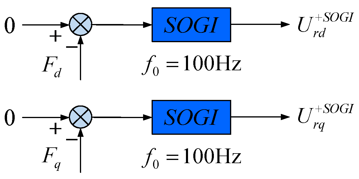
4.2. Design Process of Multi-Target Control Based on Resonant Controller

In order to achieve the above three control targets, a second-order generalized integrator (SOGI; i.e., resonant controller), which has frequency-selective control characteristics, is used in this paper to control the extended power and traditional power. The transfer function of the SOGI is shown in (23).
G S O G I ( s ) = k r 2 ω c s s 2 + 2 ω c s + ω 0 2
where ω0 is the resonant frequency, kr is the control coefficient of the resonator and ωc is the cut-off frequency used to reduce the sensitivity of the SOGI to frequency changes.
Since the main function of the resonant controller is to control the AC component of the traditional power and the extended power, the resonant frequency is set to 100 Hz. At this time, the controller has a control effect only on the 100-Hz oscillating components of the traditional power and the extended power and has little control effect over their DC components.
Therefore, the extended power resonance control can be set in the synchronous rotating coordinate system, as shown in Figure 4.
The reference value of the d and q axes of the extended power resonance control loop is set as 0. The feedback values have different forms depending on different control targets, which will be described in detail.
When the control target is target 1, it can be known from conclusion 1 that the feedback values of the extended power resonance control should be the traditional active power and the extended reactive power. It can be known from (23) that the phase gain of the resonator is 0, and the amplitude gain is kr at the resonant frequency. Therefore, the output voltage of the 100-Hz oscillating components of the traditional active power and extended reactive power after passing through the SOGI should be:
{ U r P + S O G I = k r P { 0 [ P 1 cos ( 2 ω 1 t ) + P 2 sin ( 2 ω 1 t ) ] } = 1 2 k r P P 1 2 + P 2 2 [ e j ( 2 ω 1 t arctan P 2 P 1 ) + e j ( 2 ω 1 t + arctan P 2 P 1 ) ] U r Q ˜ + S O G I = k r Q ˜ { 0 [ Q ˜ 1 cos ( 2 ω 1 t ) + Q ˜ 2 sin ( 2 ω 1 t ) ] } = 1 2 k r Q ˜ Q ˜ 1 2 + Q ˜ 2 2 [ e j ( 2 ω 1 t arctan Q ˜ 2 Q ˜ 1 ) + e j ( 2 ω 1 t + arctan Q ˜ 2 Q ˜ 1 ) ]
where U r P + S O G I and krP are the output voltage and amplitude gain of the traditional active power resonator in the rotor coordinate system, respectively, and U r Q + S O G I and krQ are the output voltage and amplitude gain of the extended reactive power resonator, respectively.
Converting the output voltage of the resonators into the rotor coordinate system, (25) can be obtained as:
{ U r P r S O G I = 1 2 k r P P 1 2 + P 2 2 [ e j [ ( 3 ω 1 ω r ) t arctan P 2 P 1 ] + e j [ ( ω 1 ω r ) t + arctan P 2 P 1 ] ] U r Q ˜ r S O G I = 1 2 k r Q ˜ Q ˜ 1 2 + Q ˜ 2 2 [ e j [ ( 3 ω 1 ω r ) t arctan Q ˜ 2 Q ˜ 1 ] + e j [ ( ω 1 ω r ) t + arctan Q ˜ 2 Q ˜ 1 ] ]
Substituting (18) into (25), (26) can be obtained as:
{ U r P r S O G I = 1 2 k r P P 1 2 + P 2 2 [ e j [ ( 3 ω 1 ω r ) t arctan P 2 P 1 ] + e j [ ( ω 1 ω r ) t + arctan P 2 P 1 ] ] U r Q ˜ r S O G I = j 1 2 k r Q ˜ P 1 2 + P 2 2 [ e j [ ( 3 ω 1 ω r ) t arctan P 2 P 1 ] e j [ ( ω 1 ω r ) t + arctan P 2 P 1 ] ]
It can be known from (26) that the necessary and sufficient condition to eliminate the harmonic component of the rotor excitation voltage with an angular frequency of 3ω1ωr, i.e., the necessary and sufficient condition for maintaining the sinusoidal stator current, is:
{ U r r S O G I = ( U r P r S O G I j U r Q ˜ r S O G I ) e j m π 2 m Z k r P = k r Q ˜
When (27) is reached, the harmonic component of (25) with an angular frequency of 3ω1ωr can be eliminated, and then (25) can be expressed as:
{ U r P r S O G I = 1 2 k r P P 1 2 + P 2 2 e j [ ( ω 1 ω r ) t + arctan P 2 P 1 ] = 1 2 k r P ( P 1 + j P 2 ) e j ( ω 1 ω r ) t U r Q ˜ r S O G I = 1 2 k r Q ˜ Q ˜ 1 2 + Q ˜ 2 2 e j [ ( ω 1 ω r ) t + arctan Q ˜ 2 Q ˜ 1 ] = 1 2 k r Q ˜ ( Q ˜ 1 + j Q ˜ 2 ) e j ( ω 1 ω r ) t
By multiplying both sides of (28) by e j ( ω 1 + ω r ) t and transforming it into the reverse synchronous rotation coordinate system, (29) can be obtained as:
{ U r P S O G I = 1 2 k r P ( P 1 + j P 2 ) = k r P ( 0 1 2 P 1 ) + j k r P ( 0 1 2 P 2 ) U r Q ˜ S O G I = 1 2 k r Q ˜ ( Q ˜ 1 + j Q ˜ 2 ) = k r Q ˜ ( 0 1 2 Q ˜ 1 ) + j k r Q ˜ ( 0 1 2 Q ˜ 2 )
It can be known from (29) that when the traditional active power and the extended reactive power are controlled by the SOGI, and the control coefficients of the resonant controller satisfy the condition in (27), the control process is equivalent to controlling P1, P2, Q ˜ 1 and Q ˜ 2 using the proportional controller in the reverse synchronous rotating coordinate system. Obviously, the feedback of the extended power resonance control should be set based on the phase relationship between P1, P2, Q ˜ 1 and Q ˜ 2 and the rotor negative sequence voltage U r d and U r q . In other words, the setting of the feedback depends on the phase relationship between P1, P2, Q ˜ 1 and Q ˜ 2 and the rotor negative sequence current I r d and I r q , since the rotor negative sequence voltage has a corresponding relationship with the phase of the rotor negative sequence current.
According to (11) and (18), (30) can be obtained as:
{ P 1 = 3 L m 2 L s U s d + + I r d + [ 3 L m 2 L s ( U s d I r d + + + U s q I r q + + ) 3 ω 1 L s ( U s q + + U s d U s d + + U s q ) ] P 2 = 3 L m 2 L s U s d + + I r q + [ 3 L m 2 L s ( U s q I r d + + U s d I r q + + ) 3 ω 1 L s ( U s d + + U s d + U s q + + U s q ) ] Q ˜ 1 = 3 L m 2 L s U s d + + I r q [ 3 L m 2 L s ( U s q I r d + + U s d I r q + + ) 3 ω 1 L s ( U s d + + U s d + U s q + + U s q ) ] Q ˜ 2 = 3 L m 2 L s U s d + + I r d + [ 3 L m 2 L s ( U s d I r d + + + U s q I r q + + ) 3 ω 1 L s ( U s q + + U s d U s d + + U s q ) ]
It can be seen that, when the control target is target 1, the feedback values should be set as:
{ F d = P s F q = Q ˜ s
When the control target is target 2, it can be known from conclusion 2 that the feedback values of the extended power resonance control should be the traditional reactive power and the extended active power.
According to (25), the output voltage of the 100-Hz oscillating components of the traditional reactive power and the extended active power passing through the SOGI can be directly written as:
{ U r Q r S O G I = 1 2 k r Q Q 1 2 + Q 2 2 [ e j [ ( 3 ω 1 ω r ) t arctan Q 2 Q 1 ] + e j [ ( ω 1 ω r ) t + arctan Q 2 Q 1 ] ] U r P ˜ r S O G I = 1 2 k r P ˜ P ˜ 1 2 + P ˜ 2 2 [ e j [ ( 3 ω 1 ω r ) t arctan P ˜ 2 P ˜ 1 ] + e j [ ( ω 1 ω r ) t + arctan P ˜ 2 P ˜ 1 ] ]
where U r Q + S O G I and krQ are the output voltage and amplitude gain of the traditional reactive power resonator in the rotor coordinate system, respectively, U r P + S O G I and krP are the output voltage and amplitude gain of the extended active power resonator in the rotor coordinate system, respectively.
Substituting (18) into (32), (33) can be obtained as:
{ U r Q r S O G I = 1 2 k r Q Q 1 2 + Q 2 2 [ e j [ ( 3 ω 1 ω r ) t arctan Q 2 Q 1 ] + e j [ ( ω 1 ω r ) t + arctan Q 2 Q 1 ] ] U r P ˜ r S O G I = j 1 2 k r P ˜ Q 1 2 + Q 2 2 [ e j [ ( 3 ω 1 ω r ) t arctan Q 2 Q 1 ] e j [ ( ω 1 ω r ) t + arctan Q 2 Q 1 ] ]
It can be seen that the necessary and sufficient condition to eliminate the harmonic component of the rotor excitation voltage with an angular frequency of 3ω1ωr, i.e., the necessary and sufficient condition for maintaining the sinusoidal stator current, is:
{ U r r S O G I = ( U r P ˜ r S O G I j U r Q r S O G I ) e j m π 2 m Z k r P ˜ = k r Q
Similar to target 1, when the control target is set to target 2, the setting of the feedback values of the extended power resonance control depends on the phase relationship between P ˜ 1 , P ˜ 2 , Q1 and Q2 and the rotor negative sequence current I r d and I r q .
According to (11) and (18), (35) can be obtained as:
{ Q 1 = 3 L m 2 L s U s d + + I r q + 3 L m 2 L s ( U s q I r d + + U s d I r q + + ) Q 2 = 3 L m 2 L s U s d + + I r d + 3 L m 2 L s ( U s d I r d + + U s q I r q + + ) P ˜ 1 = 3 L m 2 L s U s d + + I r d + 3 L m 2 L s ( U s d I r d + + U s q I r q + + ) P ˜ 2 = 3 L m 2 L s U s d + + I r q 3 L m 2 L s ( U s q I r d + + U s d I r q + + )
It can be seen that when the control target is target 2, the feedback values should be set as:
{ F d = P ˜ s F q = Q s
When the control target is target 3, it can be known from conclusion 3 that the feedback values of the extended power resonance control should be the sum of the traditional power and the corresponding extended power.
It is easy to know from (27) and (34) that if the introduction of harmonic voltage needs to be prevented, then (37) needs to be satisfied.
{ U r r S O G I = ( U r P s u m r S O G I j U r Q s u m r S O G I ) e j m π 2 m Z k r P s u m = k r Q s u m
where U r P s u m r S O G I and k r P s u m are the output voltage and amplitude gain of the active power resonant controller in the rotor coordinate system, respectively, and U r Q s u m r S O G I and k r Q s u m are the output voltage and amplitude gain of the reactive power resonator in the rotor coordinate system, respectively.
On the basis of satisfying (37), it can be known from (30) and (35) that the feedback values should be set as (38) when the control target is selected as target 3.
{ F d = P s + P ˜ s F q = Q s Q ˜ s
In summary, three control targets can be achieved by adjusting the feedback values of the extended power resonance control.

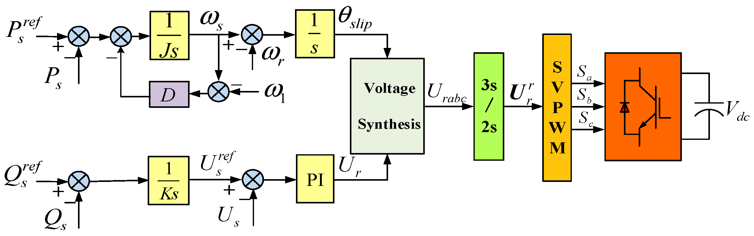
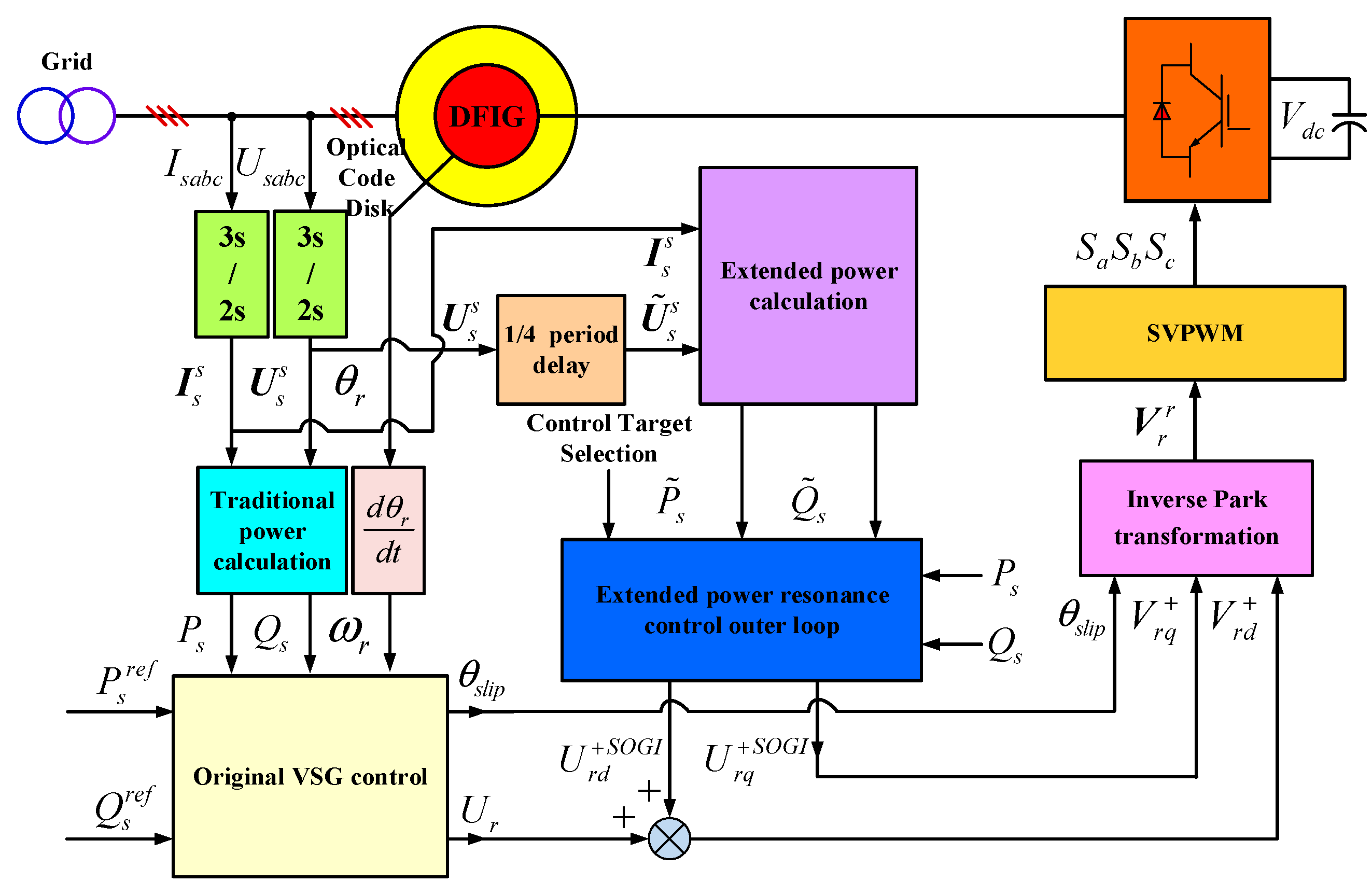
4.3. Control Block Diagram under Unbalanced Power Grid

Based on previous analysis, the control block diagram of the multi-target operation strategies of DFIG using a VSG control based on the extended power resonance control under unbalanced power grid can be illustrated in Figure 5.
In Figure 5, the multi-target operation strategies proposed in this paper adds an extended power resonance control as the outer control loop to the original VSG control. The original VSG is used to control the positive sequence and DC component of each electrical variable of the DFIG under unbalanced power grid. In the forward synchronous rotating coordinate system, the extended power resonance control is used to control the negative sequence and the AC component of each electrical variable of the DFIG by controlling the traditional power and extended power. It can be seen that this method does not change the reference and feedback of the VSG control, which avoids the problem of steady-state DC static difference caused by the inconsistency between the DC components of the traditional power and the extended power in [20]. The multi-target operation can be realized under the unbalanced power grid by changing the feedback values of the extended power resonance control according to different control targets. At the same time, the phase angle θs output by the VSG is used for orientation, and the PLL and the three-phase voltage synthesis block in the original VSG control are not necessary.

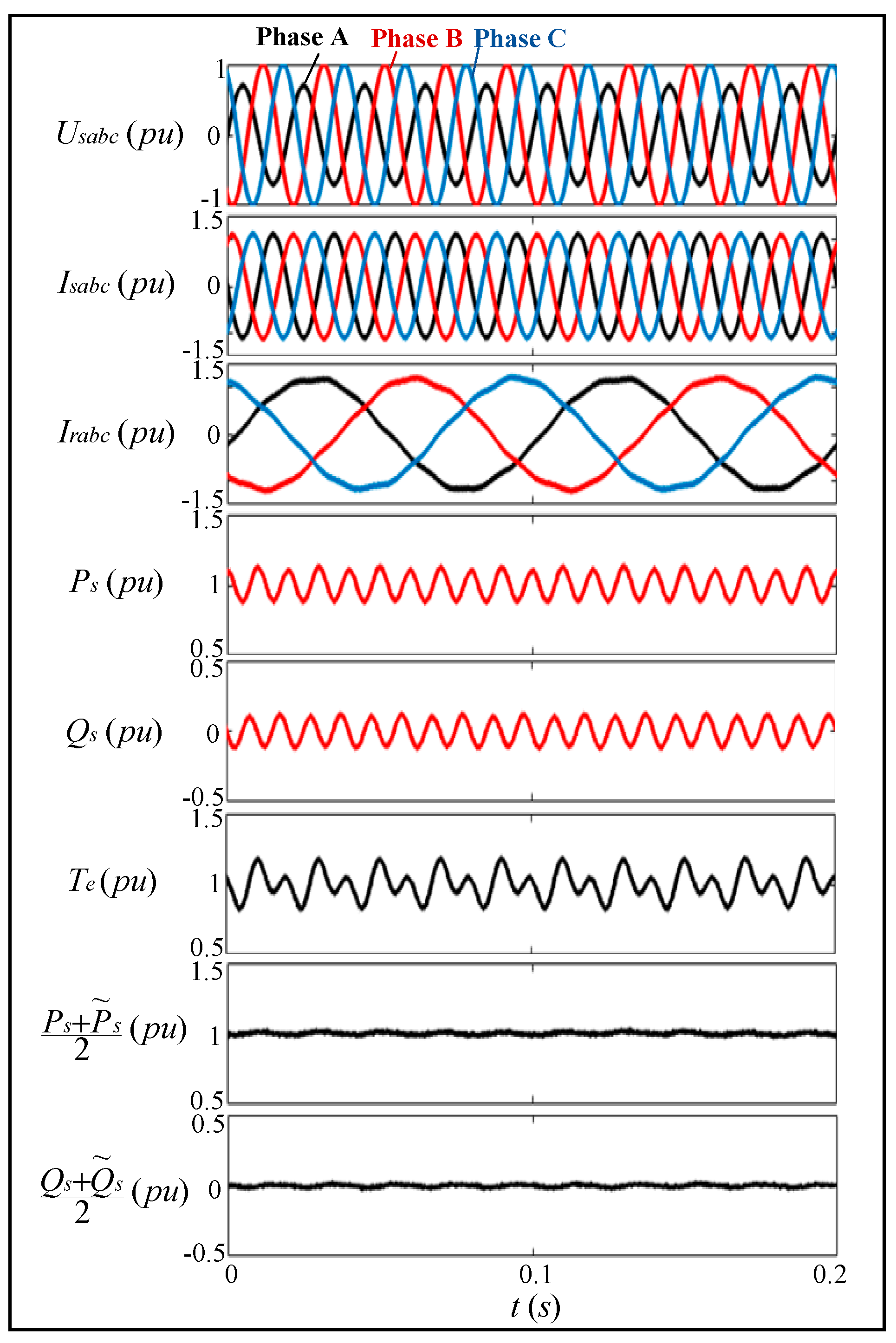
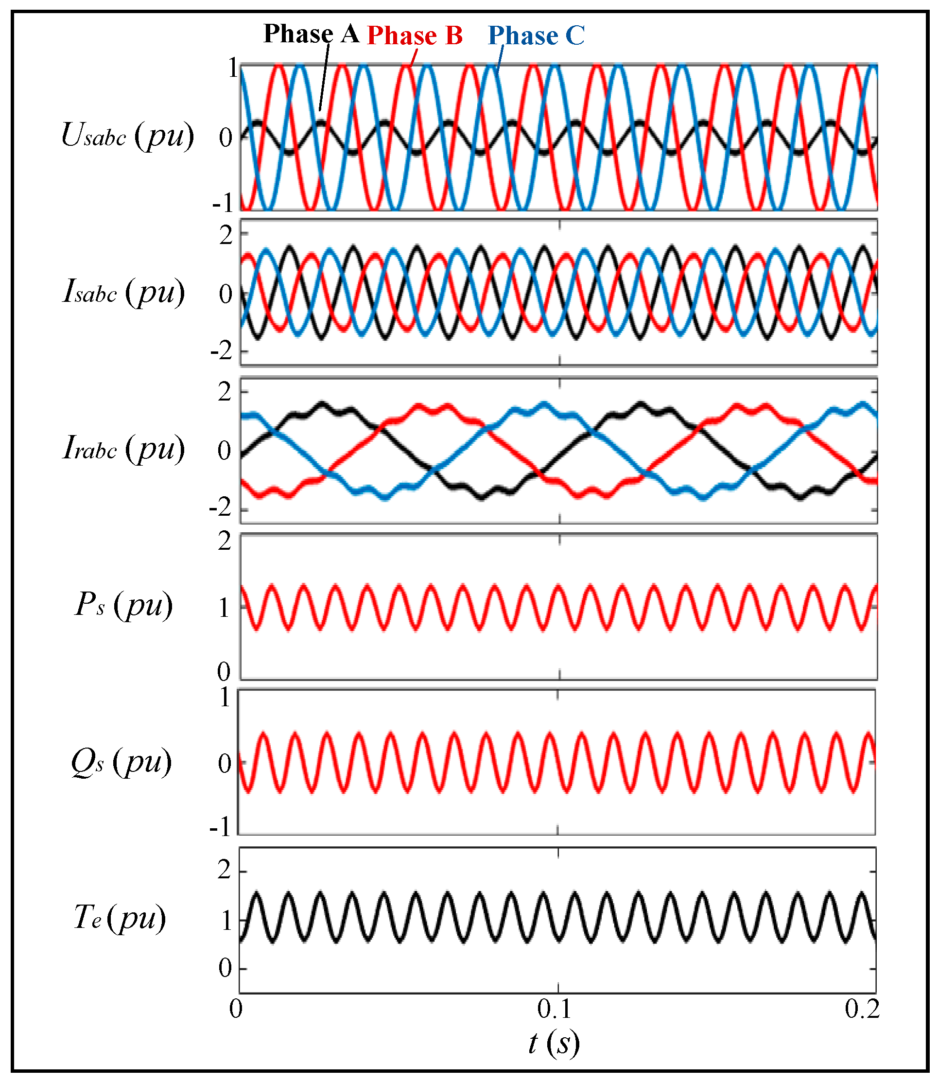
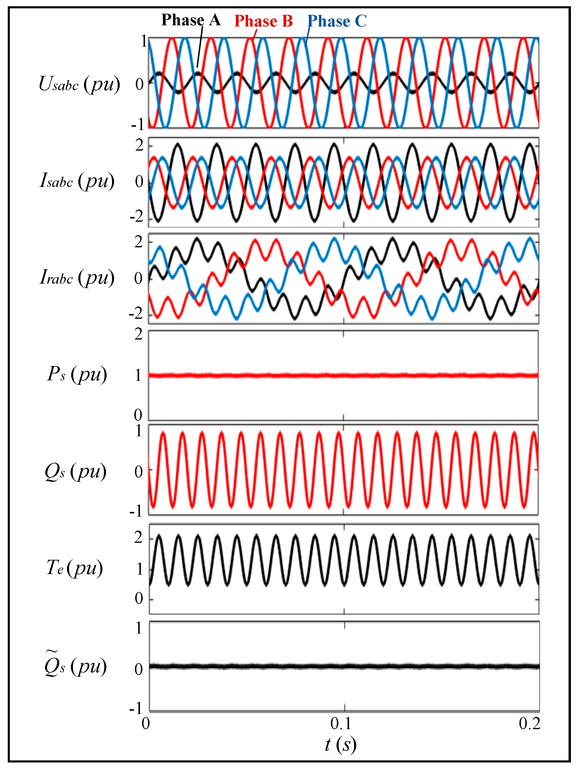
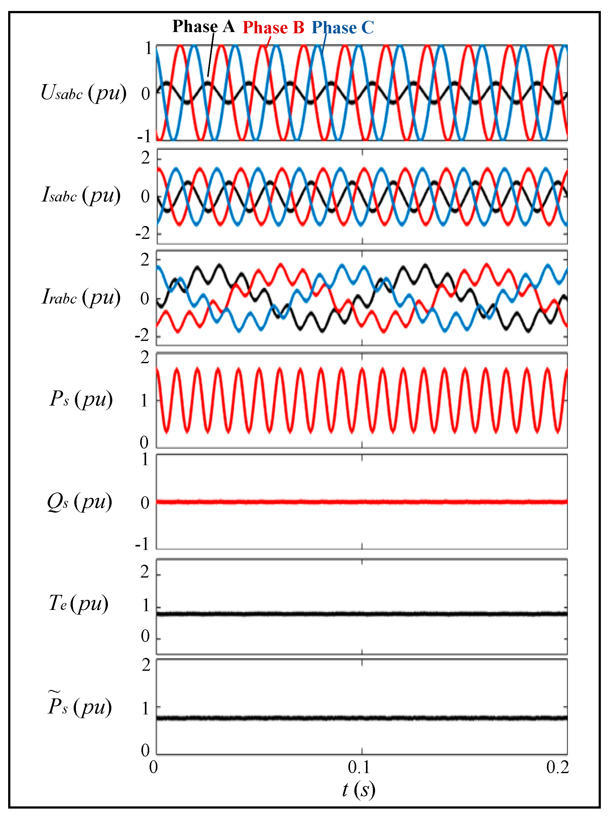
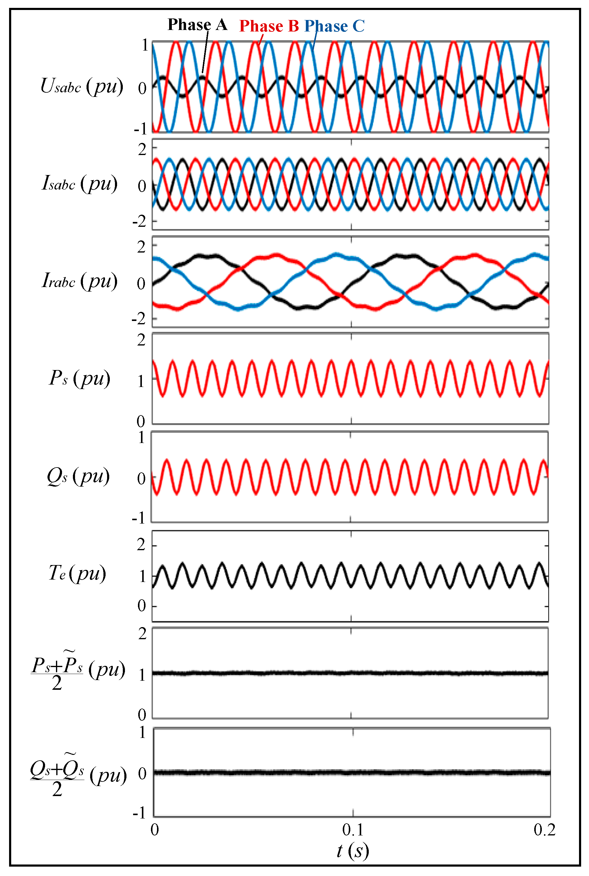
5. Simulation Studies

In this paper, the multi-target operation strategy of the DFIG using VSG control based on the extended power resonance control under different unbalanced grid conditions is simulated and verified based on MATLAB/Simulink. The system parameters in the simulation process are shown in Table 1.
During the simulation, the reference active power of the DFIG output to the grid is set to 1pu, and the reference reactive power is 0. The simulation condition of a single-phase grid voltage drop of 30% is used to simulate the unbalanced grid voltage conditions. When using the conventional VSG control strategy, the steady-state waveforms of the three-phase stator current, three-phase rotor current, active power, reactive power and electromagnetic torque are shown in Figure 6.
As shown in Figure 6, the unbalanced grid voltage causes negative sequence (−50 Hz) components in the stator current, and the unbalanced stator current also causes distortion in the rotor current. Besides, there are large double-frequency ripple components in the active and reactive power, as well as the electromagnetic torque. It can be concluded that the simulation results are consistent with the previous theoretical analysis, and the conventional VSG control has no adjustment capability for the negative-sequence current, power and torque fluctuations caused by the negative-sequence grid voltage, which will seriously affect the power quality and the operating performance of DFIG.
When using the proposed multi-target operation strategy of DFIG with VSG control based on extended power resonance control and the control target is set to target 1, target 2 and target 3, the corresponding steady-state waveforms of the three-phase stator current, three-phase rotor current, active power, reactive power and electromagnetic torque are shown in Figure 7, Figure 8 and Figure 9, respectively.
As shown in Figure 7, when the control target is set to target 1, the stator current keeps sinusoidal, and the double-frequency ripples of the active power and the extended reactive power are greatly eliminated. Therefore, the requirement of target 1 is satisfied; i.e., the stator current is sinusoidal, and the active power output from the stator is constant, which improves the output power quality of the system. It is worth noting that, when increasing the gain coefficient of the resonant controller, the power waveforms will become more ideal, but this will increase the risk of system instability.
It can be seen from Figure 8 that, when the control target is set to target 2, the reactive power, the extended active power and the electromagnetic torque are all almost constant, and the stator current keeps sinusoidal. Therefore, the requirement of target 2 is satisfied; i.e., the stator current is sinusoidal, and the reactive power and the electromagnetic torque are both constant, which avoids the impact of electromagnetic torque oscillation on the mechanical shaft and improves the operating performance of the system.
As shown in Figure 9, when the control target is set to target 3, the sum of active power and extended active power and the sum of reactive power and extended reactive power are both constant. Compared with Figure 6, it can be seen that the stator current is balanced and sinusoidal. Therefore, the requirement of target 3 is satisfied, which ensures the heat equalization of the three-phase stator windings of the DFIG.
Besides, it can also be seen from Figure 7, Figure 8 and Figure 9 that there are no DC steady-state errors in the traditional active and reactive power.
In order to verify the effectiveness of the proposed VSG control strategy under different unbalanced grid conditions, a simulation of a single-phase grid voltage drop of 80% is used to simulate more serious unbalanced conditions. The settings of the reference active and reactive power of the DFIG output to the grid remain unchanged. The simulation results of the conventional and proposed VSG control of DFIG are shown in Figure 10, Figure 11, Figure 12 and Figure 13, respectively.
It can be seen from Figure 10 that, when the unbalance of the grid voltage increases, the degree of current distortion and the double-frequency ripple components in the active and reactive power, as well as the electromagnetic torque, will become larger, which causes the power quality and operation performance of the DFIG to become worse.
As shown in Figure 11, when the control target is set to target 1, despite the greater imbalance of the grid voltage, the proposed VSG control strategy can still effectively achieve the control target of eliminating the ripple components in the active power and maintaining the stator current sinusoidal. Similarly, target 2 and target 3 can also be realized through the proposed method when the control target is switched to target 2 or target 3, as shown in Figure 12 and Figure 13. The operating performance of the VSG-based DFIG under unbalanced power grid has been improved by adopting the extended power resonance control method.
Therefore, the proposed VSG control strategy can effectively realize multi-target control under different unbalanced grid conditions, and the different control targets need to be coordinately considered according to the real-time requirements of the power grid or generator considering the priority of different requirements.
Comparing the original and proposed control strategy, it can be seen that the proposed control strategy can significantly improve the power quality and control performance of the DFIG when the grid voltage is unbalanced. The simulation results are consistent with the theoretical analysis on the proposed multi-target operation strategies of the DFIG with VSG control based on the extended power resonance control under unbalanced power grid.

6. Discussion

This paper presents a simple way to improve the operation performance of a VSG-controlled DFIG under unbalanced grid by adopting the extended power method and resonant controller.
In existing studies on either VC and DPC or VSG control for the DFIG under unbalanced grid voltage [17,18,19,21], the sequence separation module or PLL is needed, which increases the complexity of the control system. The proposed method in this paper is simple, and the sequence separation module and PLL are avoided. Besides, compared with other existing methods that can only achieve one control target, the proposed multi-target strategy increases the flexibility of the VSG-controlled DFIG system to meet different requirements of the unbalanced grid.
In this paper, the extended power method in [20] is expanded, and an extended power resonance control loop is designed and applied in a VSG-controlled DFIG system under unbalanced power grid. Compared with [20], two more control targets, i.e., balanced and sinusoidal stator current, as well as sinusoidal stator current and constant active power, are obtained based on the extended power concept; thus, a novel multi-target operation strategy for the DFIG system with VSG control under unbalanced power grid is obtained, which expands the industrial application potential of the extended power-based control strategies. In addition, compared with other existing literatures on extended power concepts, a more detailed design process of the extended power resonance control is discussed in this paper. The setting of the feedback of the extended power resonance control and the control coefficients are illustrated through analysis and mathematical derivation. Therefore, the proposed design process of the extended power-based controller is repeatable and extensible.
In order to verify the superiority of the proposed control strategy, comparative simulations are performed. The simulation results show that the VSG-based DFIG system using extended power resonance control can effectively achieve three different control targets under unbalanced grid voltage with enhanced operation performance, which proves the excellent operation ability of the proposed control strategy under unbalanced grid voltage fault.

7. Conclusions

This paper proposed a multi-target control strategy of a DFIG using VSG control based on extended power resonance control to enhance the operation performance under unbalanced grid voltage. By introducing the extended power concept and resonant controller into the conventional VSG, the proposed strategy can effectively control the DFIG according to different power quality requirements of the grid when the grid voltage is unbalanced. By analyzing the extended power, the proposed strategy can effectively realize three different control targets by simply changing the feedback of the extended power resonance controller. Meanwhile, the design process of the extended power resonance control has been discussed in detail. Besides, there is no need of PLL to monitor the phase of the grid voltage and sequence composition when using the proposed strategy. The validity of the proposed strategy has been proven by the simulation results.

Author Contributions

Conceptualization, Y.W. and D.S.; methodology, Y.W. and T.J.; software, Y.W. and T.J.; validation, Y.W. and T.J.; formal analysis, Y.W. and T.J.; data curation, D.S., X.W. and J.S.; writing—original draft preparation, Y.W. and T.J.; writing—review and editing, D.S. and Y.W.; supervision, D.S. and H.N.; project administration, D.S. and J.S. and funding acquisition, D.S. and J.S. All authors have read and agreed to the published version of the manuscript.

Funding

This research was funded by the Zhejiang Provincial Natural Science Foundation of China, grant number LZ18E070001, and the State Key Laboratory of Smart Grid Protection and Control (Project: RTDS-based modeling and simulation of virtual synchronous generator control for doubly fed induction generator).

Conflicts of Interest

The authors declare no conflicts of interest.

References

  1. Ashabani, M.; Mohamed, Y. Integrating VSCs to weak grids by nonlinear power damping controller with self-synchronization capability. IEEE Trans. Power Syst. 2014, 29, 805–814. [Google Scholar] [CrossRef]
  2. Dyanamina, G.; Kumar, A. Performance improvement of grid connected DFIG fed by three level diode clamped MLI using vector control. In Proceedings of the IEEE Region 10 Conference (TENCON), Singapore, 22–25 November 2016; pp. 560–565. [Google Scholar]
  3. Djilali, L.; Sanchez, E.N.; Belkheiri, M. Neural sliding mode field oriented control for DFIG based wind turbine. In Proceedings of the IEEE International Conference on Systems, Man, and Cybernetics, Banff, AB, Canada, 5–8 October 2017; pp. 2087–2092. [Google Scholar]
  4. Luckins, A.; Duttagupta, S.P. Model predictive control strategy for direct drive PMSG and DFIG for ocean wave energy converter system. In Proceedings of the OCEANS 2016 MTS/IEEE Monterey, Monterey, CA, USA, 19–23 September 2016; pp. 1–4. [Google Scholar]
  5. Bevrani, H.; Ise, T.; Miura, Y. Virtual synchronous generators: A survey and new perspectives. Int. J. Electr. Power Energy Syst. 2014, 54, 244–254. [Google Scholar] [CrossRef]
  6. He, X.; Geng, H.; Yang, G.; Zou, X. VSG control for DFIG-based islanded wind farm with LCC-HVDC integration. In Proceedings of the IEEE Power & Energy Society General Meeting (PESGM), Portland, OR, USA, 5–9 August 2018; pp. 1–5. [Google Scholar]
  7. Deepak, C.M.; Vijayakumari, A. Virtual inertia control for transient active power support from DFIG based wind electric system. In Proceedings of the 2nd IEEE International Conference on Recent Trends in Electronics, Information & Communication Technology, Bangalore, India, 19–20 May 2017; pp. 809–814. [Google Scholar]
  8. Shi, K.; Ye, H.; Song, W.; Zhou, G. Virtual inertia control strategy in microgrid based on virtual synchronous generator technology. IEEE Access 2018, 6, 244–254. [Google Scholar] [CrossRef]
  9. Wang, S.; Hu, J.; Yuan, X. Virtual synchronous control for grid-connected DFIG-based wind turbines. IEEE J. Emerg. Sel. Top. Power Electron. 2015, 3, 932–944. [Google Scholar] [CrossRef]
  10. Asha Rani, M.A.; Nagamani, C. An effective reference generation scheme for DFIG with unbalanced grid voltage. IEEE Trans. Sustain. Energy 2014, 5, 1010–1018. [Google Scholar] [CrossRef]
  11. Yuan, G.; Liang, R.; Hou, X. Control strategy of DFIG under unbalanced grid voltage conditions based on complex-vector-resonant regulator. In Proceedings of the 20th International Conference on Electrical Machines and Systems, Sydney, Australia, 11–14 August 2017; pp. 1–6. [Google Scholar]
  12. Abad, G.; Rodríguez, M.Á.; Iwanski, G.; Poza, J. Direct power control of doubly-fed-induction-generator-based wind turbines under unbalanced grid voltage. IEEE Trans. Power Electron. 2010, 25, 442–452. [Google Scholar] [CrossRef]
  13. Santos-Martin, D.; Rodriguez-Amenedo, J.L.; Arnalte, S. Direct power control applied to doubly fed induction generator under unbalanced grid voltage conditions. IEEE Trans. Power Electron. 2008, 23, 2328–2336. [Google Scholar] [CrossRef]
  14. Cheng, P.; Nian, H. Collaborative control of DFIG system during network unbalance using reduced-order generalized integrators. IEEE Trans. Energy Convers. 2015, 30, 453–464. [Google Scholar] [CrossRef]
  15. Reyes, M.; Rodriguez, P. Enhanced decoupled double synchronous reference frame current controller for unbalanced grid-voltage conditions. IEEE Trans. Power Electron. 2012, 27, 3934–3943. [Google Scholar] [CrossRef]
  16. Nian, H.; Cheng, P. Independent operation of DFIG-based WECS using resonant feedback compensators under unbalanced grid voltage conditions. IEEE Trans. Power Electron. 2015, 30, 3650–3661. [Google Scholar] [CrossRef]
  17. Wang, H.; Zhang, W. Improved dual-PI rotor current control scheme for a wind-driven DFIG during asymmetrical grid voltage dips. In Proceedings of the IEEE International Electric Machines and Drives Conference, Miami, FL, USA, 3–6 May 2009; pp. 171–176. [Google Scholar]
  18. Hu, J.; He, Y. Reinforced control and operation of DFIG-based wind-power-generation system under unbalanced grid voltage conditions. IEEE Trans. Energy Convers. 2009, 24, 905–915. [Google Scholar] [CrossRef]
  19. Hu, J.; Zhu, J.; Dorrell, D.G. Model-predictive direct power control of doubly-fed induction generators under unbalanced grid voltage conditions in wind energy applications. IET Renew. Power Gener. 2014, 8, 687–695. [Google Scholar] [CrossRef]
  20. Sun, D.; Wang, X. A sliding-mode direct power control strategy for DFIG under both balanced and unbalanced grid conditions using extended active power. IEEE Trans. Power Electron. 2018, 33, 1313–1322. [Google Scholar] [CrossRef]
  21. Jiao, Y.; Nian, H.; He, G. Control strategy based on virtual synchronous generator of DFIG-based wind turbine under unbalanced grid voltage. In Proceedings of the 20th International Conference on Electrical Machines and Systems, Sydney, Australia, 11–14 August 2017; pp. 1–6. [Google Scholar]
Figure 1. Active power-frequency control loop of virtual synchronous generator (VSG).
Energies 13 02232 g001
Figure 2. Reactive power-voltage control loop of VSG.
Energies 13 02232 g002
Figure 3. Virtual synchronous generator control of a doubly fed induction generator (DFIG).
Energies 13 02232 g003
Figure 4. Extended power resonance control loop.
Energies 13 02232 g004
Figure 5. Multi-target operation strategies of the DFIG using VSG control based on the extended power resonance control under unbalanced grid.
Energies 13 02232 g005
Figure 6. Conventional VSG control under a single-phase grid voltage drop of 30%.
Energies 13 02232 g006
Figure 7. Proposed VSG control under a single-phase grid voltage drop of 30% (Target 1).
Energies 13 02232 g007
Figure 8. Proposed VSG control under a single-phase grid voltage drop of 30% (Target 2).
Energies 13 02232 g008
Figure 9. Proposed VSG control under a single-phase grid voltage drop of 30% (Target 3).
Energies 13 02232 g009
Figure 10. Conventional VSG control under a single-phase grid voltage drop of 80%.
Energies 13 02232 g010
Figure 11. Proposed VSG control under a single-phase grid voltage drop of 80% (Target 1).
Energies 13 02232 g011
Figure 12. Proposed VSG control under a single-phase grid voltage drop of 80% (Target 2).
Energies 13 02232 g012
Figure 13. Proposed VSG control under a single-phase grid voltage drop of 80% (Target 3).
Energies 13 02232 g013
Table 1. System parameters of the doubly fed induction generator (DFIG) control system.
Motor ParametersParameter Values
Nominal l-l voltage Us0690 V(rms)
Rated power Ps02 MW
Rated Frequency ω150 Hz
Stator leakage inductance Lls0.102 pu
Rotor leakage inductance Llr0.11 pu
Mutual inductance Lm11.3 pu
Stator resistance Rs0.0108 pu
Rotor resistance Rr0.0121 pu
Turns ratio (rotor over stator)2.835
DC Voltage Vdc
slip ratio s
1200 V
0.2
Control ParametersParameter Values
Virtual inertia J0.2
Damping coefficient D3
Excitation adjustment factor K0.33
PI Proportionality coefficient Kp1
PI Integral coefficient Ki2
Resonator control coefficient kr100

