Abstract
In wireless charging devices, a transmitter that applies a single inverter to output dual-frequency can effectively solve the charging incompatibility problem caused by different wireless charging standards and reduce the equipment volume. However, it is very difficult to solve the switching angle of the modulated dual-frequency waveform, which involves non-linear high-dimensional multi-objective optimization with multiple constraints. In this paper, an improved differential evolution (DE) algorithm is proposed to solve the transcendental equations of switching angle trains of dual-frequency programmed harmonic modulation (PHM) waveform. The proposed algorithm maintains diversity while preserving the elites and improves the convergence speed of the solution. The advantage of the proposed algorithm was verified by comparing with non-dominated sorting genetic algorithm II (NSGA II) and multi-objective particle swarm optimization (MOPSO). The simulation and experimental results validate that the proposed method can output dual-frequency with a single inverter for wireless power transfer (WPT).
1. Introduction
The wireless power transfer (WPT) systems transmit electrical power from the power supply to the load without any wired connection [1]. It avoids potential safety hazards such as hot-plugging and wire shorting in wired power transmission, which greatly increases safety. With the continuous development of technology, WPT has been widely used in the fields of portable electronics, implantable medical devices, electric vehicles [2,3,4,5], and so on. The rapid development of WPT technology has inspired an era of wireless charging.
Although WPT technology has the above advantages, there are also some challenges in the field of wireless charging, such as inconsistent charging frequency standards and the need to transmit information in the wireless charging process.
Currently, there are several international standards in the wireless charging field. In February 2017, the Wireless Power Consortium officially published the Qi interface standard and the low-power specification [6]. The Aviation Fuel Alliance gave the wireless power transfer system baseline system specification (BSS) [7] in 2014. This difference in frequency standards will bring great inconvenience to consumers and manufacturers. Wireless charging devices designed by manufacturers according to different charging standards are not compatible with each other. Mobile electronic devices with different charging standards must be equipped with a charger corresponding to the charging standard, which limits the application and promotion of wireless charging products.
In some areas of wireless power transmission, such as implantable medical devices [8], field fire alarm [9], etc., it is necessary to transmit information while transmitting power. Despite many advances in the field of simultaneous wireless information and power transfer (SWIPT) [10,11], there are still some challenges. The fundamental and third harmonics of the triangle current waveform are used for power and information transmission, respectively [12]. Unfortunately, its information transmission rate is limited and cannot be further improved. A multifrequency superposition method [13] is proposed for a magnetically coupled resonant WPT system with multiple loads. However, this increases the energy loss of the system and system complexity. The dual-frequency (DF) inverter can work in different frequency bands, which can be used to effectively solve the problem of inconsistent charging frequency standards. At the same time, the system can also be used for simultaneous transmission of electrical power and information [14] and it does not need additional information channel, which simplifies the system topology and improves the transmission efficiency.
The DF-inverter employs dual-frequency programmed harmonic modulation (PHM). Unlike the traditional pulse width modulation (PWM) [15] which only generates a fundamental frequency and restrains limited harmonics, the DF-inverter with PHM needs to output two frequencies at the same time. The greater the difference between the two frequencies of the output, the more harmonics need to be eliminated, and the more pure the output frequency. The advantage is that it is easy to distinguish the two output frequencies while avoiding mutual interference, which helps to reduce the difficulty of demodulation. Therefore, in practical applications, these two frequencies usually differ greatly which increases the difficulty of implementation.
Dual-frequency PHM achieves dual-frequency output by solving a set of switching angles. The difficulty of this method implementation mainly lies in the calculation of inverter switching angles, because it is essentially a nonlinear optimization problem with multivariable, high dimension and complex constraints. If the lower frequency of the DF-inverter output is regarded as the fundamental, the higher frequency is the high-order harmonic. Considering that the frequency ranges specified by different charging standards differ greatly, the high frequency of the DF-inverter output will be very large, and inevitably, the number of switching angles of the inverter will be large. Increasing the number of preset switch angles will greatly increase the difficulty of finding solutions. Therefore, the compatibility of different standards and the far-reaching frequency distribution are contradictory.
In view of the above consideration, this paper combines the DE algorithm with the Newton iteration method to solve the dual-frequency modulation switching angle of the DF-inverter. The principle of wave-forming of DF-inverter was analyzed and a mathematical model was established. Considering it is a high-dimensional multi-objective problem, the Pareto frontier was introduced, and the adaptive operator was added to the mutation, which increased the global search ability of the algorithm. Moreover, by combining with the Newton iteration method, the convergence speed of the algorithm improved.
The purpose of this paper is to propose an improved DE to produce the dual-frequency with a single inverter. The remainder of this paper is organized as follows. Section 2 summarizes related works of the method of solving the switching angle. Section 3 presents the principle of dual-frequency PHM. Section 4 develops an improved DE algorithm for the dual-frequency switching angle. Several multi-objective algorithm comparisons and DF inverter’s simulation and experimental results are provided in Section 5. Finally, Section 6 draws the conclusions.
2. Related Works
At present, the algorithm for solving the switching angle is mainly divided into two categories. One is the numerical methods, such as Newton–Raphson method [16,17], homotopy algorithm [18,19], etc. The other one is the optimization method, such as particle swarm optimization algorithm [20], ant colony algorithm [21], artificial bee colony [22] and so on.
All numerical methods require the selection of appropriate initial values. Unfortunately, there is still no literature on how to choose the appropriate initial value. An algebraic method combining Groebner bases with symmetric polynomials [23] is proposed to solve the switching angle. It can get rid of the constraint of initial value selection and avoids solving the multivariate high-order equations, which greatly simplifies the solution process. Even if the maximum solvable switch angle is increased to nine, it still cannot meet the large number of switching angles of the dual-frequency output required in practical applications. In addition, with the increase in solving the switching angle, the computational complexity of the numerical methods increases. Considering the limitations of the numerical method itself, it is not suitable for solving the switching angle of the DF-inverter.
The optimization method does not have to preset initial value. Its idea is to convert the solving switching angle sequence into multi-objective optimization. The genetic algorithm has been used to selectively eliminate harmonics (SHE) by changing the fitness function [24] and control the basic voltage component according to the modulation index. A modulation of an 11-stage cascade multilevel inverter by combining a genetic algorithm with an artificial neural network [25] was proposed to solve a switching angle that varies with the DC power supply. DE is one of the most powerful stochastic real-parameter optimization algorithms and was first proposed by Storn and Price. It has been widely used to optimize multiple engineering problems due to its advantages in maintaining population diversity and searching ability [26,27,28]. For example, a composite DE is proposed to improve the global searching ability and convergence rate of the solution by combining multiple combination trial vectors and reasonably setting control parameters [29]. DE is also applied in multilevel voltage source inverter (MVSI) [30] to realize harmonic elimination, which can achieve a wide range of fundamental output voltage while maintaining very low total harmonic distortion.
According to the above analysis, in the publications on optimization methods, optimization algorithms have been widely used to solve the selected harmonic elimination pulse width modulation (SHEPWM), which only retains the fundamental of the low frequency and eliminates all other high-order harmonics. However, in a dual-frequency scenario, two specific frequencies need to be reserved. Although only one extra nonzero frequency is added, the difficulty of solving is greatly increased. The optimization method must be improved to solve the optimization problem under the condition of multivariable, high dimension and nonlinear complex constraints.
3. The Principle of Dual-Frequency PHM
The structure diagram of the DF-inverter is shown in Figure 1. The two phase-legs (Q1, Q2, Q3, Q4) form a full-bridge inverter, which can output two frequencies simultaneously by controlling the turn-on and turn-off timing of the switches. The DF-inverter output is presented in the form of a composite frequency, which typically includes a low-frequency and a high-frequency component.
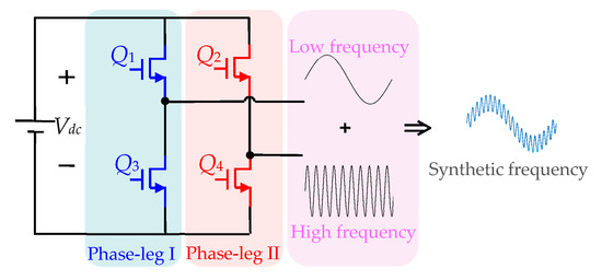
Figure 1.
Topology of GaN-based single phase full bridge inverter.
Figure 2a shows a bipolar dual-frequency PHM waveform with an odd number of switching angles in the 1/4 cycle. The waveform is a quarter period symmetric waveform, so the calculation can be simplified by analyzing its 1/4 period. The in Figure 2b is the switching angle (), which is the phase angle sequence of the switches, and represents each pulse width in the figure, and its physical significance is the time interval between two adjacent switching angles. Since the waveform is a quarter periodic symmetric waveform, even harmonics are automatically eliminated, and only odd harmonic components exist.

Figure 2.
(a) Bipolar dual-frequency programmed harmonic modulation (PHM) waveform and (b) its quarter cycle.
The output voltage could be represented as a Fourier series,
The corresponding frequency component derived from Equation (1) is
where Vdc is the input DC voltage of the inverter, Vac1 (fundamental frequency) and Vac2 (high frequency) represent the desired magnitudes of two output frequencies. To simplify the subsequent analysis and experiments, the modulation index of the fundamental frequency and high frequency is defined as the value of output AC voltage normalized by DC voltage, M1 = Vac1/Vdc, M2 = Vac2/Vdc. It is assumed that Vdc = 1 and the output voltage (Vac1 and Vac2) are equal to their respective modulation indices. The m is the highest harmonic that can be eliminated. To avoid transcendental equations, m is set to 2N − 1 to form a square matrix, where N is the number of switches in the quarter symmetrical period.
Once the switching angles within the quarter symmetric waveform are found, from the waveform characteristics of Figure 2a, the remaining angle values can be obtained from the following formula:
According to Equation (2), if the greatest common divisor of the two frequencies is the fundamental frequency component, it can calculate any harmonic combination. This gives the flexibility of the choice of dual-frequency PHM output frequency. At the same time, the higher the order of the high frequency of the modulated output relative to the fundamental frequency, the more switching angles are required.
As for SHEPWM, it eliminates the low-order harmonics, retains and outputs only the fundamental frequency component that is the only nonzero component in the switching angle solution system. However, the dual-frequency PHM requires that two components are nonzero in the switching equations, which greatly increases the difficulty of solving the switching angle. In addition, the two output frequencies should be separated as far as possible to reduce the interference between the two frequencies. Consequently, it increases the order of the high-frequency components, which undoubtedly increases the number of switching angles and the dimension of the equations.
Based on the above analysis, considering the complexity of solving the switching angle of dual-frequency PHM, an improved DE algorithm combined with Newton iteration is adopted to solve the problem.
4. Proposed Improved DE Algorithm
The problem of solving the switching angle of dual-frequency PHM can be transformed into finding an optimal solution for the following equations, that is, finding a set of switching angles that can satisfy the following constraints simultaneously.
where N is the number of switching angles in a quarter cycle of the symmetric square wave, and m is the highest harmonic order that can be eliminated (m = 2N − 1). and are the lower and upper bounds of the j-th switching angle, respectively. Considering that the waveform is modulated within a quarter of a period, the range of (,) is (0, π/2).
The proposed algorithm in this paper introduces the concept of the Pareto frontier on the basis of DE, adds an adaptive mutation operator in the variation link, improves the global search ability of the algorithm, and reduces the possibility of falling into the local optimal solution. After that, the value obtained by evolution is taken as the initial value and iterated into the Newton iterative algorithm. The general structure of the improved DE algorithm is shown in Figure 3.
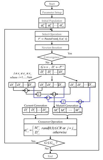
Figure 3.
Flowchart for the improved DE optimization.
The cross operation in this algorithm is consistent with the classical DE algorithm, and will not be described here. The termination condition of the algorithm program is that the evolution exceeds the preset maximum evolutionary generation. The remaining main steps to solve the dual-frequency PHM switch angle using the improved DE algorithm are as follows.
4.1. Parameter Setup
The parameters required by the improved algorithm include solution space dimension (N), population size (NP), mutation factor (F0), crossover probability (CR), boundary constraint condition (, ), DC input voltage (Vdc) and expected amplitude of two output frequencies Vac1 (fundamental frequency) and Vac2 (High frequency). The boundary must satisfy Equation (5), and F0 and CR are within the range of [0, 1].
4.2. Initial Population
The initial generation population is randomly initialized according to Equation (6).
where the represents the initial generation i-th group switching angle in the population, and the represents the j-th switching angle in . The number of groups of switching angles is expressed by NP. rand ( ) is a random number randomly distributed within the interval of (0, 1). Since each set of values is the switching angle within a quarter of a week and its angle should increase with time, the switching angle () in each set of values should also be sorted from small to large after initializing the population.
4.3. Selection
One of the main differences between the proposed algorithm in this paper and the classic DE is the selection. The proposed algorithm uses the concept of the Pareto frontier non-dominated solution to sort the equations corresponding to each set of switching angles of this generation and obtains the Pareto frontier of the equation solution, thus obtaining the Pareto frontier of each set of switching angles () as a high-quality individual into the next generation of evolution.
According to the properties of the Pareto front, the number of switching angle groups in the Pareto front must be less than or equal to the population size NP. Assuming that the number of Pareto frontier switching angular groups is Num, then i = 1, 2, 3, ..., Num in , where Num ≤ NP.
4.4. Newton Iteration
The Newton iteration method has strong convergence, but its limitation is that it needs a suitable initial value. The introduction of Newton’s algorithm can speed up the convergence of the proposed algorithm, especially in the later stage of the algorithm. Each set of in the Pareto front obtained in Section 4.3 is taken as the initial value to be iterated by the Newton iteration method. The convergence of Newton’s iteration is determined by setting the solution accuracy. When the solution accuracy is satisfied, the algorithm converges, and the accuracy is set to 10−4 (unit: degree) in this algorithm. If the iteration is convergent and the switching angle boundary condition is satisfied, it indicates that a set of switching angles is successfully found. At this time, the set of switching angle values is output and the algorithm is terminated. Otherwise, perform Section 4.5.
Considering that Newton iteration requires initial values with high precision, the initial value obtained by the selection operation may not meet the requirement. Therefore, it is necessary to set an upper limit on the number of iterations to reduce the iteration time and prevent invalid iterations. In this paper, the maximum number of iterations is set to 10 times.
4.5. Mutation Operation
The individual mutation in DE is achieved by randomly selecting two different individuals in a population and synthesizing the vectors with the mutated individuals after scaling their vector differences. Evolution in each generation is accompanied by individual mutation.
The mutation operation formula is as follows:
where, G stands for evolutionary generation; r1, r2, and r3 are three random numbers that are not equal to i and less than or equal to Num; F is a proportional factor with a range of [0, 1]; is a population of G-th generation, producing intermediate by mutation.
In order to improve the global search ability of the solution and avoid falling into the local optimum, the mutation chain adopts the adaptive mutation operator. The formula is as follows,
where Gm is the maximum evolutionary generation and G stands for current evolutionary generation. The mutation operator has a larger value (2F0) in the early evolution stage to maintain individual diversity, thus avoiding premature maturity. With the increase of evolutionary generation, the mutation operator gradually reduces to F0 to retain good individual information.
The mutated individuals may not meet the preset boundary conditions in which case it is necessary to judge whether in the individual after mutation meets the boundary condition. For the that does not meet the boundary condition, the method of Section 4.2 shall be adopted to regenerate them until the boundary conditions are satisfied.
5. Verification
To verify the effectiveness of the improved DE algorithm proposed in this paper for solving the switching angle of a single inverter to achieve dual-frequency output, the improved DE was compared with the existing multi-objective algorithm, and the switching angles obtained by the improved DE was verified by simulation and experiment with the DF inverter.
5.1. Algorithm Comparison
In order to illustrate the effectiveness of the improved DE algorithm in solving dual-frequency PHM switching angles and the performance in solving multidimensional multi-objective optimization problems, the proposed algorithm is compared with non-dominated sorting genetic algorithm II (NSGA II) [31] and multi-objective particle swarm optimization (MOPSO) [32] about the solving time of solving 2, 3, 5 and 10 switching angles of dual-frequency PHM with different solving accuracy.
The parameters of the algorithm are set as follows. In the improved DE, NP = 10N, CR = 0.9, F0 = 0.5. The population size of NSGA II is 200, the crossover probability is 0.9, the mutation probability is 1/N, the simulated binary crossover of ηc = 20 and the polynomial mutation strategy of ηm = 20 are adopted. The population size of MOPSO is 200, the external population size is 200, and the number of mesh divisions of each dimension in the adaptive mesh is 50. The inertia weight decreases linearly with evaluation times from ω0 = 0.7 to ω1 = 0.2 and the two acceleration constants are r1 = r2 = 2.0. Each algorithm runs randomly 10 times for each solution condition. When the estimated times of the objective function reaches 10,000 times, the algorithm stops running. Table 1 describes the time taken by the three algorithms to solve 2, 3, 5 and 10 switching angles of dual-frequency PHM with different solution accuracy (10−3 or 10−4).

Table 1.
Time required for three algorithms to solve dual-frequency PHM switching angles with different accuracy (time unit: second).
From the comparison of the data obtained in Table 1, it can be found that the improved DE is better than NSGA II and MOPSO in terms of solution time and ability to solve more objectives. The improvement of the solution accuracy has almost no impact on the performance of the algorithm. NSGA II has good performance in solving two and three objective problems, but with the increase of the number of solving problems, the performance of NSGA II drops sharply, and five switching angles cannot be solved under the maximum evaluation times. With the increase in the number of objectives, the solution time of MOPSO increases obviously, and it is very sensitive to the solution precision. The improvement of the solution precision will greatly increase the solution time. Under the set parameters, this algorithm can only solve five switching angles.
This comparative study shows that the improved DE is more suitable for solving multi-objective problems, especially when the number of objectives is more than five, NSGA II and MOPSO lose the solving ability and the improved DE still has solving capability.
5.2. Simulation Verification
In the verification process of simulation and experiments, the number of switching angles in the 1/4 cycle is determined to be 20 (N = 20). The fundamental frequency output is 10 kHz, and the 37th harmonic (370 kHz) is used as the high-frequency output. When the DC voltage is 10 V, the amplitude of the fundamental frequency voltage and the high-frequency voltage is 6 V. Therefore, the parameter in Equation (4) is set to Vac1 = Vac2 = 0.6, Vdc = 1. The quarter-cycle switching angle under the solution accuracy of 10−4 can be obtained, as shown in Table 2. The parameters in the simulation model and experimental circuit are shown in Table 3.

Table 2.
Values to bipolar 20 switching-angle case (unit: degree) when Vac1 = Vac2 = 0.6 (normalized), k = 37.

Table 3.
Simulation and experimental parameters.
MATLAB/Simulink is used as the simulation tool to verify the improved algorithm. The topology of the DF-inverter system simulation circuit in this paper is shown in Figure 4. A full-bridge inverter has been formed using two GaN-based phase-legs. L1 and C1 resonate at the fundamental frequency, L2 and C2 form high-frequency resonance tank.
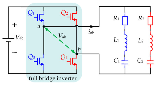
Figure 4.
The topology of dual-frequency PHM inverter.
The waveform of the output voltage Vab of the inverter within one cycle is obtained by simulation as shown in Figure 5, which displays the turn-on and turn-off angle of the inverter. The FFT result is shown in Figure 6. The fundamental frequency and the 37th harmonic amplitude are about 6 V, which is basically consistent with the set value, and the harmonics between the two pre-output frequencies are completely eliminated, in accordance with the expected effect.
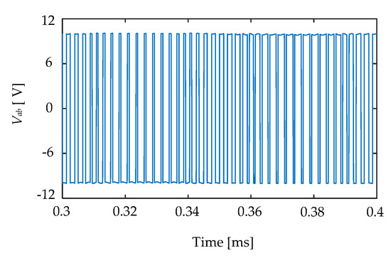
Figure 5.
The output voltage Vab of the inverter.
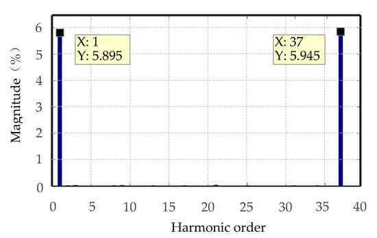
Figure 6.
FFT results of Vab.
The resonant tanks L1-C1-R1 and L2-C2-R2 separate the fundamental and high-frequency components of the inverter output, respectively. The load voltage waveforms of the fundamental and high-frequency are shown in Figure 7. As can be seen from the waveform in the figure above, the waveform is smooth on the whole and the amplitude is relatively stable, but there are some small ripples in the waveform which is caused by other harmonics higher than the 37th harmonic.
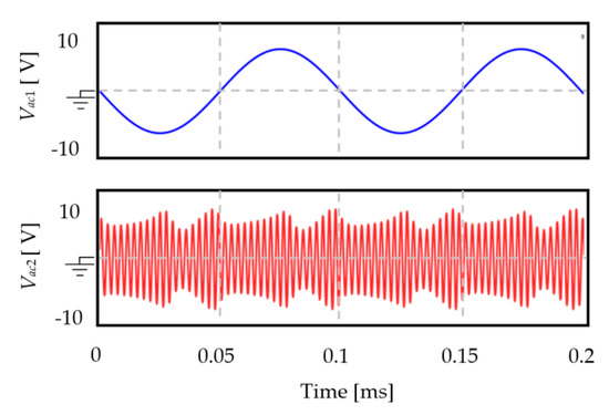
Figure 7.
Load voltage of two resonant branches.
5.3. Experimental Verification
An experimental platform was set up to verify the proposed algorithm, as shown in Figure 8. The experimental system used an FPGA chip EP4CE10F17C8 as the controller to generate dual-frequency PHM signals. After obtaining the predetermined switching angle by off-line calculation of the algorithm, the control resolution of the system hardware was improved by doubling the clock frequency of the FPGA system to 400 MHz, which improved the experimental precision of the dual-frequency PHM signal. Considering that the inverter works under high-frequency switching, a GaN-based inverter was used, which can operate at frequencies up to several MHz. The component parameters of the experimental system were consistent with the simulation parameters setting.
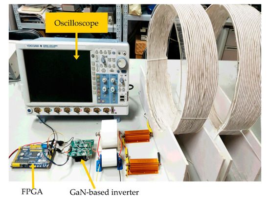
Figure 8.
Experimental platform.
Experimental voltage waveforms of the full-bridge inverter output Vab, and the load voltage Vac1 and Vac2 of the high and low frequency resonant branch are shown in Figure 9, respectively, where Vab is the dual-frequency PHM waveform which is generated by the system. Its Fourier analysis is shown in Figure 10a, where the amplitude of the residual harmonics between the two frequencies is severely attenuated. In addition to the pre-output frequency, the amplitudes of the 36th and 38th harmonics were observable in the frequency range from the fundamental frequency to the 40th harmonic, but their amplitudes were only 0.611 V and 0.628 V, respectively, and the contents of other harmonics were lower. The amplitudes of the fundamental frequency and the preset high-frequency components were basically consistent with the simulation results, but the harmonics near the preset high-frequency components were not completely eliminated in the experiment, which was caused by the insufficient control resolution of the experimental platform. However, its amplitude was also very low, which was acceptable.
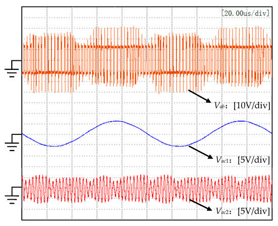
Figure 9.
Experimental waveforms at Vac1 = Vac2 = 0.6 (normalized), Vdc = 10 V and k = 37. (Full-bridge voltage Vab, fundamental frequency load voltage Vac1, and high-frequency load voltage Vac2).
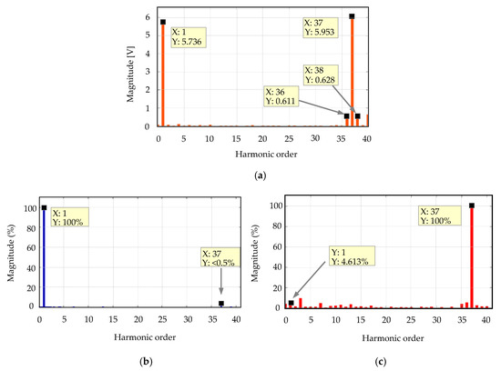
Figure 10.
Spectrums of (a) Vab, (b) Vac1, and (c) Vac2.
Figure 10b,c shows the spectrum of Vac1 and Vac2, respectively. In Figure 10b, the pre-output high-frequency component in the low-frequency branch accounts for less than 0.5% of the fundamental frequency component. The proportion of the fundamental frequency component in the high-frequency branch in Figure 10c is only 4.613% of the high-frequency component. It can be seen that the corresponding resonant frequency component in the resonance branch is large and the rest harmonic components are small, which indicates that the two frequencies generated by the system are separated very well.
As shown in Table 4, the improved DE was used to obtain the values at bipolar 20 switching angles when Vac1 = 0.8, Vac2 = 0.4 (normalized), and k = 39. Experiments were performed under the conditions of Vdc = 20 V, fundamental frequency 15 kHz, and high-frequency 585 kHz (39th harmonic) to obtain the full-bridge output voltage and its spectrum analysis results, as shown in Figure 11. The experimental results are basically consistent with the expected values, which proves the effectiveness and accuracy of the improved DE once again.

Table 4.
Values to bipolar 20 switching-angle case (unit: degree) when Vac1 = 0.8, Vac2 = 0.4 (normalized), k = 39.
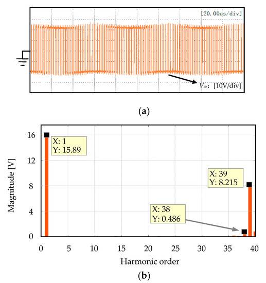
Figure 11.
Experimental waveforms at Vac1 = 0.8, Vac2 = 0.4 (normalized), Vdc = 20 V and k = 39. (a) Full bridge voltage Vab and (b) its spectrums.
6. Conclusions
The dual-frequency PHM is essentially a high-dimensional multi-objective problem with complex constraints. The classic DE cannot solve this kind of problem. In this paper, an improved algorithm based on DE is proposed, which provides a solution for solving the switching angle of the dual-frequency output of a single inverter. In this algorithm, the Newton iterative method is combined with DE. By rationally utilizing the strong convergence of Newton’s method and the diversity of DE, the efficiency of the solution is improved. In addition, the adaptive mutation operator is used in the mutation process, which can effectively avoid the program falling into local optimum and premature phenomenon. The simulation analysis and experimental results are consistent with the expectation, and the feasibility of the proposed algorithm is verified. The algorithm can be used to solve the dual-frequency and multifrequency switching angles of a single inverter and is also suitable for the optimization of multi-objective and multidimensional problems.
Author Contributions
Conceptualization, J.W.; investigation, L.G.; methodology, J.W., L.B., N.J. and V.S.; resources, J.Z. and J.T.; supervision, N.J.; validation, L.B.; writing—original draft, J.W., L.B. and N.J.; writing—review and editing, J.W. and V.S. All authors have read and agreed to the published version of the manuscript.
Funding
This work was supported in part by the National Natural Science Foundation of China under the grant U1604136 and by the Scientific and Technological Program of Henan Province under the grant 202102210090.
Conflicts of Interest
The authors declare no conflict of interest.
References
- Kurs, A.; Karalis, A.; Moffatt, R.; Joannopoulos, J.D.; Fisher, P.; Soljačić, M. Wireless power transfer via strongly coupled magnetic resonances. Science 2007, 317, 83–86. [Google Scholar] [CrossRef] [PubMed]
- Sugahara, S.; Matsunaga, S. Fundamental study of influence of ripple noise from DC-DC converter on spurious noise of wireless portable equipment. IEEE Trans. Power Electron. 2013, 31, 2111–2119. [Google Scholar] [CrossRef]
- Kim, J.; Kim, H.; Kim, D.; Park, H.-J.; Ban, K.; Ahn, S.; Park, S.-M. A Wireless Power Transfer Based Implantable ECG Monitoring Device. Energies 2020, 13, 905. [Google Scholar] [CrossRef]
- Seong, J.Y.; Lee, S.-S. Optimization of the Alignment Method for an Electric Vehicle Magnetic Field Wireless Power Transfer System Using a Low-Frequency Ferrite Rod Antenna. Energies 2019, 12, 4689. [Google Scholar] [CrossRef]
- De Marco, D.; Dolara, A.; Longo, M.; Yaïci, W. Design and Performance Analysis of Pads for Dynamic Wireless Charging of EVs using the Finite Element Method. Energies 2019, 12, 4139. [Google Scholar] [CrossRef]
- Wireless Power Consortium. The Qi Wireless Power Transfer System Power Class 0 Specification, Version 1.2.3. February 2017. Available online: https://www.wirelesspowerconsortium.com/ (accessed on 1 February 2017).
- AirFuel. A4WP Wireless Power Transfer System Baseline System Specification, BSS Standard A4WP-S-0001 v1.2. January 2014. Available online: https://airfuel.org/ (accessed on 1 January 2014).
- Abdulfattah, A.N.; Tsimenidis, C.C.; Al-Jewad, B.Z.; Yakovlev, A. Performance analysis of MICS-based RF wireless power transfer system for implantable medical devices. IEEE Access 2019, 7, 11775–11782. [Google Scholar] [CrossRef]
- Lin, W.; Ziolkowski, R.W. Electrically small huygens antenna-based fully-integrated wireless power transfer and communication system. IEEE Access 2019, 7, 39762–39769. [Google Scholar] [CrossRef]
- Wu, J.; Zhao, C.; Lin, Z.; Du, J.; Hu, Y.; He, X. Wireless power and data transfer via a common inductive link using frequency division multiplexing. IEEE Trans. Ind. Electron. 2015, 62, 7810–7820. [Google Scholar] [CrossRef]
- Wu, J.; Zhao, C.; Jin, N.; He, S.; Ma, D. Bidirectional information transmission in SWIPT system with single controlled chopper receiver. Electronics 2019, 8, 1027. [Google Scholar] [CrossRef]
- Yan, Z.; Xiang, Z.; Wu, L.; Wang, B. Study of Wireless Power and Information Transmission Technology Based on the Triangular Current Waveform. IEEE Trans. Power Electron. 2018, 33, 1368–1377. [Google Scholar] [CrossRef]
- Liu, F.; Yang, Y.; Ding, Z.; Chen, X.; Kennel, R.M. A multifrequency superposition methodology to achieve high efficiency and targeted power distribution for a multiload MCR WPT system. IEEE Trans. Power Electron. 2018, 33, 9005–9016. [Google Scholar] [CrossRef]
- Wu, J.; Li, Y.; Jin, N.; Deng, W.; Tang, H.; Snášel, V. A GaN-based wireless power and information transmission method using dual-frequency programmed harmonic modulation. IEEE Access 2020, 8, 49848–49856. [Google Scholar] [CrossRef]
- Buccella, C.; Cecati, C.; Cimoroni, M.G.; Kulothungan, G.; Edpuganti, A.; Rathore, A.K. A selective harmonic elimination method for five-level converters for distributed generation. IEEE J. Emerg. Sel. Topics Power Electron. 2017, 5, 775–783. [Google Scholar] [CrossRef]
- Memon, M.A.; Mekhilef, S.; Mubin, M.; Aamir, M. Selective harmonic elimination in inverters using bio-inspired intelligent algorithms for renewable energy conversion applications: A review. Renew. Sust. Energy Rev. 2018, 82, 2235–2253. [Google Scholar] [CrossRef]
- Kouro, S.; Malinowski, M.; Gopakumar, K. Recent advances and industrial applications of multilevel converters. IEEE Trans. Ind. Electron. 2010, 57, 2553–2580. [Google Scholar] [CrossRef]
- Ning, L.; Tong, G.; Hui, Z.; Ping, Y. Comparative research of harmonic suppression algorithm of the three-level NPC converter. J. Eng. 2019, 2019, 1271–1274. [Google Scholar] [CrossRef]
- Aghdam, G.H. Optimised active harmonic elimination technique for three-level T-type inverters. IET Power Electron. 2013, 6, 425–433. [Google Scholar] [CrossRef]
- Etesami, M.; Ghasemi, N.; Vilathgamuwa, D.M.; Malan, W.L. Particle swarm optimisation-based modified SHE method for cascaded H-bridge multilevel inverters. IET Power Electron. 2017, 10, 18–28. [Google Scholar] [CrossRef]
- Haghdar, K. Optimal DC source influence on selective harmonic elimination in multilevel inverters using teaching–learning-based optimization. IEEE Trans. Ind. Electron. 2020, 67, 942–949. [Google Scholar] [CrossRef]
- Mousavi, S.Y.M.; Laharami, M.Z.; Kumle, A.N.; Fathi, S.H. Application of ABC algorithm for selective harmonic elimination switching pattern of cascade multilevel inverter with unequal DC sources. Int. Trans. Elect. Energy Syst. 2018, 28, e2522. [Google Scholar] [CrossRef]
- Yang, K.; Zhang, Q.; Yuan, R.; Yu, W.; Yuan, J.; Wang, J. Selective harmonic elimination with groebner bases and symmetric polynomials. IEEE Trans. Power Electron. 2016, 31, 2742–2752. [Google Scholar] [CrossRef]
- Lee, S.S.; Chu, B.; Idris, N.R.N.; Goh, H.H.; Heng, Y.E. Switched-battery boost-multilevel inverter with GA optimized SHEPWM for standalone application. IEEE Trans. Ind. Electron. 2016, 63, 2133–2142. [Google Scholar] [CrossRef]
- Filho, F.; Maia, H.Z.; Mateus, T.H.A.; Ozpineci, B.; Tolbert, L.M.; Pinto, J.O.P. Adaptive selective harmonic minimization based on ANNs for cascade multilevel inverters with varying DC sources. IEEE Trans. Ind. Electron. 2013, 60, 1955–1962. [Google Scholar] [CrossRef]
- Das, S.; Suganthan, P.N. Differential Evolution: A Survey of the State-of-the-Art. IEEE Trans. Evol. Comput. 2011, 15, 4–31. [Google Scholar] [CrossRef]
- Sutton, A.M.; Lunacek, M.; Whitley, L.D. Differential evolution and non-separability: Using selective pressure to focus search. In Proceedings of the 9th Annual Conference on Genetic and Evolutionary Computation (GECCO ’07), London, UK, 7–11 July 2007; Association for Computing Machinery: New York, NY, USA, 2007; pp. 1428–1435. [Google Scholar]
- Pattanaik, J.K.; Basu, M.; Dash, D.P. Opposition-based differential evolution for hydrothermal power system. Power Syst. Prot. Control 2017, 2, 40–56. [Google Scholar] [CrossRef]
- Yu, Y.; Zhang, P.; Song, Z.; Chai, F. Composite differential evolution algorithm for SHM with low carrier ratio. IET Power Electron. 2018, 11, 1101–1109. [Google Scholar] [CrossRef]
- Salam, Z.; Majed, A.; Amjad, A.M. Design and implementation of 15-level cascaded multi-level voltage source inverter with harmonics elimination pulse-width modulation using differential evolution method. IET Power Electron. 2015, 8, 1740–1748. [Google Scholar] [CrossRef]
- Ye, B.; Shi, X.; Wang, X.; Wu, H. Optimisation configuration of hybrid AC/DC microgrid containing electric vehicles based on the NSGA-II algorithm. J. Eng. 2019, 2019, 7229–7236. [Google Scholar] [CrossRef]
- Yang, Y.; Shang, Z.; Chen, Y.; Chen, Y. Multi-Objective Particle Swarm Optimization Algorithm for Multi-Step Electric Load Forecasting. Energies 2020, 13, 532. [Google Scholar] [CrossRef]
© 2020 by the authors. Licensee MDPI, Basel, Switzerland. This article is an open access article distributed under the terms and conditions of the Creative Commons Attribution (CC BY) license (http://creativecommons.org/licenses/by/4.0/).