Article

System Designs and Experimental Assessment of a Seven-Mode Vehicle-Oriented Hybrid Powertrain Platform

1
Undergraduate Program of Vehicle and Energy Engineering, National Taiwan Normal University, Taipei 106, Taiwan
2
Department of Industrial Education, National Taiwan Normal University, Taipei 106, Taiwan
3
Department of Vehicle Engineering, National Formosa University, Taipei 106, Taiwan
*
Author to whom correspondence should be addressed.
Energies 2020, 13(8), 2104; https://doi.org/10.3390/en13082104
Submission received: 3 March 2020 / Revised: 16 April 2020 / Accepted: 18 April 2020 / Published: 23 April 2020
(This article belongs to the Section E: Electric Vehicles)

Abstract

:
This study developed a mechatronics platform for a seven-mode vehicle-oriented powertrain system. The innovative “all-in-one” concept was used for flexibly arranging various power or energy sources to be combined for various hybrid powertrains. Hence, it significantly reduces the cost and human resources for evaluating new-type power systems or developed vehicle control strategies on the same experimental platform. In this study, three power sources were chosen for providing hybrid power. The first source is a 125 c.c. spark ignition (SI) engine, where a controllable throttle valve governs the output torque, while a fuel meter measures the consumed fuel. The second one is a 1.5kW hub motor, where a motor control unit (MCU) and a 48V lithium battery pack properly provide the required electric power. The third source is an air engine, where a 220V air compressor and other components provide the pneumatic power. For the experimental platform, a developed Matlab/Simulink package receives the measured signals and sends the control commands to actuators. Through the on/off state control of three controllable e-clutches, three single-source modes, three dual-source modes, and one three-source mode (3+3+1) can be conducted. A 1.1kW/24V magnetic powder brake emulates the road load. The results show that three dual-source modes and a three-source mode were successfully operated. The efficiencies, torques and speeds, mass flow rates, etc. have been measured and calculated. This platform is aimed for the research fields of green energies, advanced powertrains, and power flow management.

1. Introduction

Nowadays, the hybrid powertrain systems as well as the hybrid green energy sources are the main stream for advanced vehicles [1,2]. Although battery electric vehicles (BEVs) have become much more popular recently, the obstacles of mass commercialization, such as: charging station/battery exchange station, low power density of lithium batteries are still crucial for the transportations. Hence, regarding the power-assist devices for electric vehicles, the gasoline engine or diesel engine, as well as another zero-pollutant power sources, the air-powered traction motor (engine) [3], become much more popular nowadays.
For engine/motor hybrid powertrains, the vehicle types majorly include: series, parallel, and series/parallel hybrid electric vehicles (HEVs) [4]. From the large output power ratio to the small power ratio of the engine when compared to the traction motor, the vehicle types can be classified to be power-assist HEVs [5], full-hybrid HEVs [6], plug-in HEVs [7], and the range-extension electric vehicles (RE-EVs) [8]. Several hybrid-powertrain experimental platforms have been constructed prior to the vehicle development in order to evaluate the performances as well as the design of the vehicle control unit (VCU) of the hybrid powertrains [9,10,11,12]. In [9], a prototyping hybrid powertrain platform with a transient hydrostatic dynamometer for the purpose of emulating dynamics of various hybrid sources and different hybrid architectures, was constructed. In [10], a parallel hybrid-electric bus model was constructed, where each model subsystem was separately validated by test bench experiment. The model behavior was compared with that of real target part on testbed and modified if it was inaccurate. In [11], a test platform for "hybrid electric power systems" (HEPS) was developed, where it serves as a platform for research and education and it can optimize the energy flow in HEPS. From above, all experimental platform was less than two power sources and the system flexibility and usages were limited. Hence, by our multi-source experimental platform, the R&D cost, and development period will be significantly reduced if various powertrain developments are required.
To satisfy the concept of “clean zone”, besides the electric motor, the zero-pollutant power sources, the air motor (air engine) was chosen as another vehicle power source. The advantages of an air motor when compared with the electric motor are summarized in [12]. Many studies have modeled or constructed the experimental platform for the air motor (vane-type or scroll-type) [13,14,15,16]. In [13], a fuzzy MRAC controller design for vane-type air motor systems was developed. In [14,15], the mathematical modeling of scroll air motors and energy efficiency analysis have been conducted. In [16], a hybrid pneumatic-power vehicle was constructed. The optimization of the internal-combustion and recycling of the exhaust energy can increase the efficiency from an original 15% to 33%. Key variables, such as the pressures, temperatures, and air flow rates inner the air motor can be calculated, according to the geometric shape of the air motor, as well as the thermodynamics equations [3]. In [17], a hybrid pneumatic-power system that recycles exhaust gas of an internal-combustion engine was developed. In [18], a hybrid pneumatic-power system was established for optimizing the thermal efficiency of the powertrain. In this study, an engine drove a compressor to drive the air motor. The engine waste heat was then delivered to drive the air motor. The results showed that 20% system efficiency was improved. In [19], an air-powered motorcycle was produced, which was equipped a high-pressure tank and the van-type air motor for the on road test with a fuzzy logic controller. In [20], an air-supply station was designed and constructed. By using the high-pressure accumulator, an AC220V compressor, and a pressure boost cylinder, the two-mode air charging mechanism was accomplished. A self-produced air/electric scooter was tested on the dynamometer.
According to aforementioned studies, although many experimental platforms and numerical models for two power sources have been established for performance assessment prior to real-vehicle usages, a complicated experimental platform for three power sources has not been developed in previous research. The innovative platform in this study is able to produce seven operation modes on a single platform: three single-source modes ( C 1 3 ) (engine, air engine, electric motor), three dual-source modes ( C 2 3 ) (engine/electric motor, electric motor/air engine, air engine /engine), and one three-source mode ( C 3 3 ) (engine/electric motor/air engine). Through this platform, combined with the control system and mechatronics, various operation scenarios and hybridization of power sources, verification of vehicle control unit (VCU), and performance evaluation of hybrid powertrains can be conducted. The main contributions of the present study can be summarized, as follows: 1) mechanical designs of the power sources, energy providing systems, and the power engage/disengage devices were successfully integrated; 2) the system mechatronics and harness were constructed; 3) the Matlab/Simulink program for the mode switch and actuator control were completed; and, 4) the test results of engine/electric motor, electric motor/air engine, air engine /engine, and engine/air engine/electric motor were achieved by this research.

2. Experimental Platform Designs and Mode Control

2.1. Experimental Platform Designs

The experimental platform was designed to integrate three power sources, energy sources, and to measure the key variables, as shown in Figure 1. It was separated into four segments. The first segment (energy path) is the electric motor (in-wheel type), where a lithium battery module provided the DC power to the motor control unit (MCU). After the proper switch of power-drive components, the hub motor provided traction power to the out load. For the signal measurements, the power sensor measured the output DC power from the battery, while the torque meter 3 (TM3) and speed sensor 3 (SS3) detected the output torque and speed of the hub motor. For the control signal, the VCU delivered the proper command voltage to the MCU. The second segment is the air engine, where an AC 220V air compressor pumped the compressed air to an air tank as a pneumatic energy storage device or an energy buffer to stabilize the output air flow rate. The air from the tank then propelled the piston of the air engine to produce the traction power. For the signal measurements, a mass flow meter (MFM) was mounted to evaluate the input power (force) at the air engine inlet. The torque meter 2 (TM2) and speed sensor 2 (SS2) detected the output torque and speed of the air engine. For the control signal, the VCU sent the command voltage to a proportional valve for the purpose of regulating the air flow energy to the air engine. The third segment is the four-stroke SI engine, where a fuel tank delivered the fuel energy to the engine. For the signal measurements, a flow meter (FM) was interconnected to the intake manifold to evaluate the consumed energy of the fuel. For the control signal, the VCU sent the command voltage to a step motor (SM) to control the throttle to manage the air/fuel mixture to the engine. The torque meter 1 (TM1) and speed sensor 1 (SS1) detected the output torque and speed of the engine. The fourth segment is the magnetic powder brake, where the command voltage was proportional to the load torque and was sent by the VCU in order to emulate the road load. The output energy of the three power sources can be combined and disengaged by three electric clutches. Clutch 3 (C3) was for the electric motor, clutch 2 (C2) was for the air engine, while clutch 1 (C1) was for the engine. Two chain gear sets delivered the power between two shafts. Shaft 1 linked the hub motor and the magnetic powder brake, while shaft 2 directly linked the air engine and the engine.
Figure 2 illustrates the scheme of the three-power-source experimental platform following the concept design illustrated in Figure 1. The three-dimensional (3D) plot showed that the position of the key components, sensors, and mountings were properly arranged.

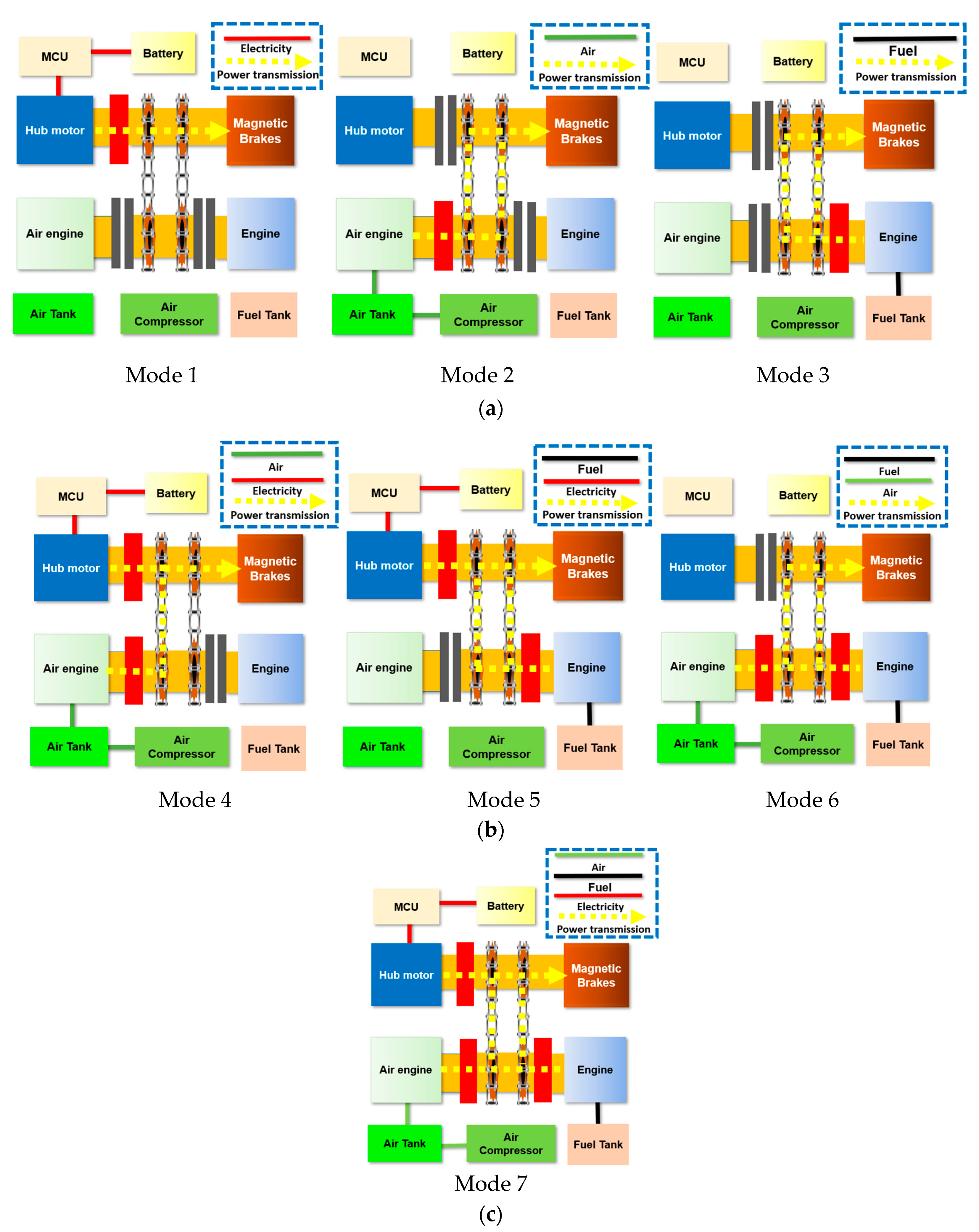
2.2. Seven Operation Modes

From Section 2.1, the three power sources produced seven operation modes. Figure 3 demonstrates the relationships between the energy (power) flow and the actions of components. In Figure 3a, from the left, the Mode 1: hub motor mode means the power was solely delivered by the hub motor, where the electric power was given by the battery, through the MCU, and then to the hub motor. As C3 was engaged, the power was directly transferred to the magnetic powder brake. The middle is the Mode 2: the air engine mode, where the pneumatic energy from the air compressor, the air tank was sent to the air engine on the second shaft. With the engagement of C2 and the power transmission of two chain gear sets, the power can be transferred from shaft 2 to shaft 1, and then to the load. The right is the Mode 3: the engine mode, where the chemical energy of the gasoline was transferred to the mechanical power from the engine. As C3 was engaged on shaft 2, the chain gears sent the power to the load on shaft 1. Figure 3b illustrates the three hybrid modes of dual power source. Mode 4 (left) was the hub motor/air engine mode, where C2 and C3 were on so that the air power from shaft 2 and the hub motor power from shaft 1 were combined and then sent to the out load. Mode 5 (middle) was the hub motor/engine mode, where C1 and C3 were on, and the hub motor power from shaft 1 and the engine power from shaft 2 were linked and sent to the out load. Mode 6 (right) was the air engine /engine mode, where C1 and C2 were engaged. The air engine power and the engine power from shaft 2 were transferred through the chain gear sets to the out load. Mode 7: the triple source mode (Figure 3c) shows that all three clutches were engaged. Energy from all power sources was delivered to the out load. From the above introduction, the controller can be integrated to form the closed-loop control.

2.3. Control Strategies

The control strategy for the seven modes was coded on the Matlab/Simulink environment to properly control the complicated experimental platform, as shown in Figure 4. For the input signals, the interface can be selected from the “Advantech pci-1720-u card”, “Advantech pci-1716 card”, and “Advantech pci-1240 card” toolbox. The input signals (from the top) were: (1) hub motor torque: the analog signal was measured by the TM3 (see Figure 1); (2) air engine flow: the analog signal was measured by the MFM; (3) air engine pressure: the analog signal was measured by the pressure sensor (PS); (4) air engine torque: the analog signal was measured by the TM2; (5) total output torque: the analog signal was measured by the TM1; (6) air engine speed: the analog signal was measured by SS2; (7) engine speed: the analog signal was measured by SS1; (8) battery voltage: the analog signal was measured by the power sensor downstream the battery; (9) battery current: the analog signal was measured by the same power sensor; and, (10) hub motor speed: the analog signal was measured by the SS3.
For the output ports, the physical meaning of them, from the top, can be listed, as follows: (1) hub motor control voltage ( V m ): the analog output signal is for the MCU to provide the proper output motor speed; (2) air engine throttle control voltage ( V m f m ): the analog output signal is for the step motor to control the throttle position of the air engine; (3) engine throttle control voltage ( V s m ): the analog output signal is for the step motor to control the throttle position of the engine; (4) magnetic brake control voltage ( V m b ): the analog control signal is proportional to the loading torque; (5) C3 control voltage ( V c 3 ): the analog signal is for the electric clutch on/off downstream the hub motor; (6) C2 control voltage ( V c 2 ): the analog signal is for the electric clutch on/off downstream the air engine; (7) C1 control voltage ( V c 1 ): the analog signal is for the electric clutch on/off downstream the engine.
For the control strategy of the seven mode, it is shown in Table 1. For single power source mode, only one clutch is engaged (C1 for engine mode; C2 for air engine mode; C3 for hub motor mode). For dual power sources mode, (1) Engine + Hub-motor: the hub motor and the C3 will activate first and reach a constant speed, while the engine throttle starts to open to raise the engine speed. Subsequently, the C1 is on, as the engine speed equals to the motor speed. The hybrid engine/motor power is reached. (2) Engine + Air engine: the engine activates first to a constant operation speed with C1 is on. The air engine is then activated as the air throttle provides the compressed air into the air engine, the C2 is then engaged when the motor speed equals the engine speed. (3) Hub motor + air engine: the hub motor and the C3 will activate first and to a constant speed, while the air engine throttle starts to open to raise the speed. The C2 is then on as the air engine speed equals to the hub motor speed. The hybrid hub motor/air engine power is reached.

3. Experimental Platform and Mechatronics System

In this section, the three power source subsystems were first developed based on the system designs and the mechatronics in Section 2. Subsequently, the experimental platform was constructed according to Figure 1 and Figure 2. The control system then was integrated into the platform for the closed-loop control.

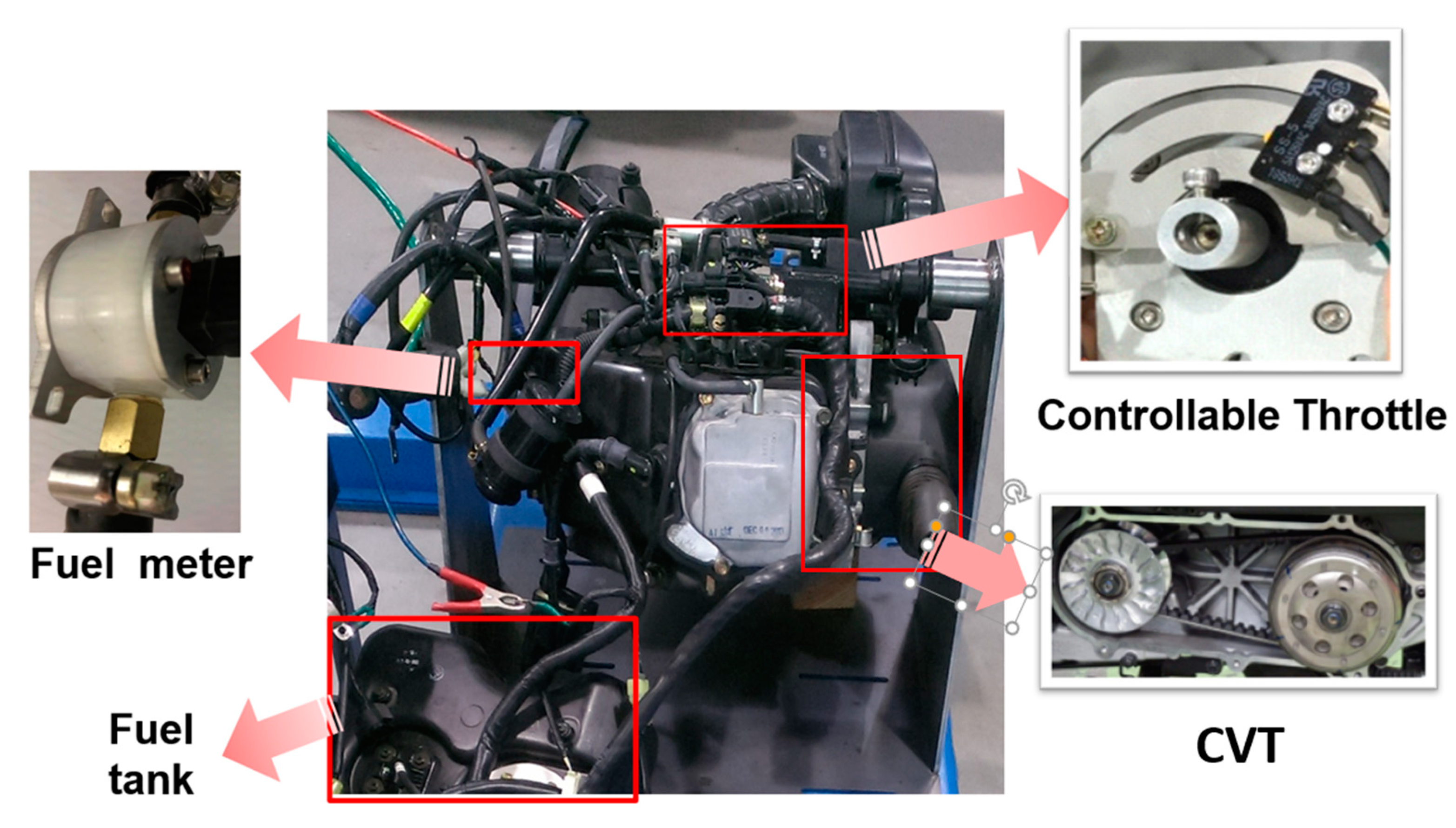
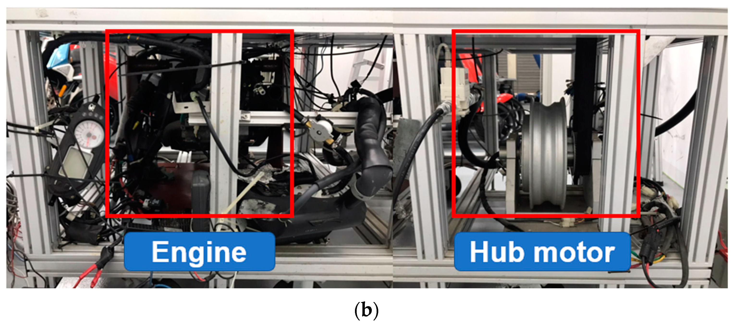
3.1. SI Engine System

The engine is a 125c.c. four-stroke SI engine. For the system integration, it was mounted below the platform, which was linked with a sprocket chain to drive the outload (see Figure 5). To vary the output torque (power), a controllable throttle with a 0–5V stepper motor analog signal command was placed in the front part of the intake manifold to manage the input air/fuel mixture. A fuel meter (FCH-m-POM-HD, Bio Tech, Germany) was equipped at the rear part of the fuel pump inner the fuel tank to evaluate the total fuel consumption and to record the instant fuel economy. To properly and efficiently operate the engine, a continuously variable transmission (CVT) was equipped at the rear part of the engine, where the torque meter 1 (TM1) and the speed sensor 1 (SS1) were mounted at the output shaft of the CVT. The efficiency of the engine with the CVT system can be expressed as:
η e = P e , o / P e , i = τ e ω e / ( L H V × m ˙ e )
where the efficiency of the engine system (including the CVT), as denoted by η e , is the output power P e , o (output torque τ e multiplied by output speed ω e ) divided by the input theoretical inner power P e , i of the fuel (low heating value, LHV, multiplied by the mass flow rate m ˙ e ).

3.2. Traction Motor System

For the zero-emission power source, a 1kW brushless DC hub motor was selected, as shown in Figure 6. The 48V lithium battery package provided the required electric power to the MCU, which transfers the DC power to proper signal wave by the power circuits to drive the motor. A current sensor detected the current value, as combined with the battery voltage, the power can be derived to measure the output electric power from the battery. The efficiency of the hub motor can be expressed as:
η m = P m , o / P m , i = τ m ω m / ( I m V m )
where the efficiency of the hub motor system, denoted by η m , is the output power P m , o (output motor torque τ m multiplied by output motor speed ω m ) divided by the input electric power P m , i (DC current I m multiplied by the input DC voltage V m ).

3.3. Air Engine System

The other zero-pollutant power source, an air propulsion system was established, as shown in Figure 7. An AC 220V air compressor provided the compressed air to the air tank, where it can stabilize the air pressure and guaranteed the long-period test. A mass flow meter was equipped after the air tank to calculate the instant air mass flow rate and the accumulated air mass. Moreover, a throttle valve inside controls the mass flow rate entering the air engine. A pressure regulator was equipped to measure the air power as well as to further realize the variation of pneumatic power. The air energy was then pumped into the air engine to propel the piston as well as the rotational shaft.
The efficiency of the air engine system can be formulated as:
η a e = τ a e ω a e / ( P a e × m ˙ a e )
where the efficiency of the air engine, denoted by η a e , is the output power P a e , o (output air engine torque τ a e multiplied by output air engine speed ω a e ) divided by the input pneumatic power P a e , i (the inlet pressure of the air engine P a e multiplied by the mass flow rate of the compressed air m ˙ a e ).
The above three power system will be integrated into the three-power-source platform, which is described in Section 3.4.

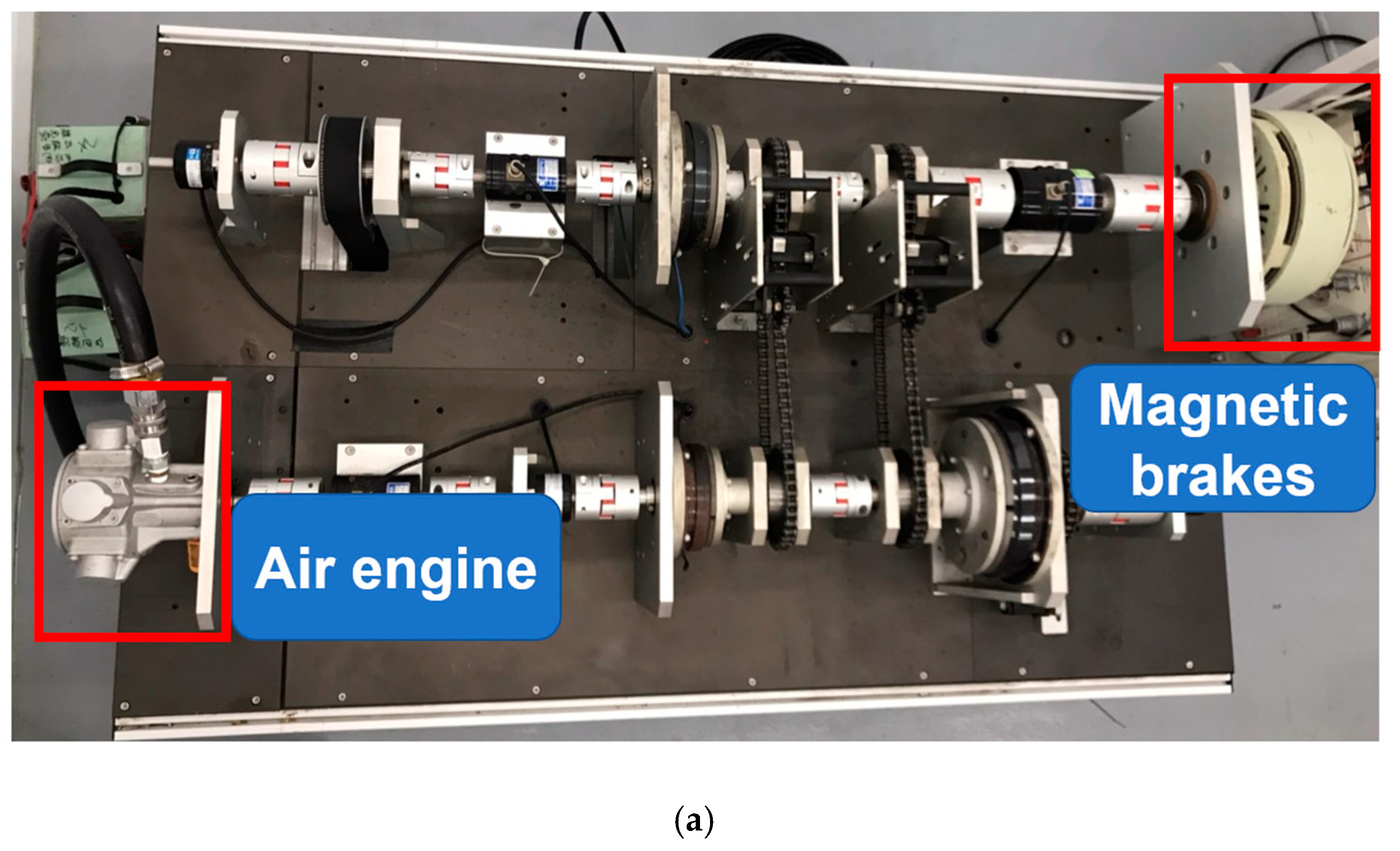
3.4. Three-Power-Source Platform Establishment

According to Figure 1 and Figure 2, and the three power sources from Figure 5 to Figure 7, the experimental platform was built, as shown in Figure 8. Figure 8a shows the top view of the system with two main shafts, three clutches and two belts links the three power sources, and the out load. Due to the limitation of the platform space, Figure 8b demonstrates that the hub motor and the 125 c.c. SI engine was integrated below the platform.
The I/O ports and the harness should be defined and setup to properly manage the power sources. Figure 9 illustrates that two I/O boards governs the control voltages and feedback signals. For Board A, the front side output signals to the board include: the torque sensors of the hub motor (denoted as number 1 in Figure 9), the air engine (number 7) and the output shaft (gross torque sensor) (number 3), the air engine pressure sensor (number 2), the battery voltage sensor (number 4), the battery current sensor (number 9), the speed sensors of the engine (number 10), hub motor (number 8) and the air engine (number 5), and the air engine mass flow sensor (number 6). The front side output signals from Board A are the control voltage of the motor control unit of the hub motor (number 11) and the control voltage of the throttle of the air engine (number 12). For back side of Board A, the output signal to the board is the engine fuel meter sensor (number 16), while the input signal to the board includes: the step motor control signals (number 13 and 18) and the control voltages for C1 (number 17), C2 (number 15), and C3 (number 14), respectively. For the front side of Board B, the signals are the control voltage of the magnetic brake (number 19) and the pressure signal from the pressure regulator of the air engine (number 20). The seven mode experimental platform is completed according to the system designs and the mechatronics integration.

4. Experimental Results and Discussion

This section demonstrates the results of the three-power-source experimental platform with four operation modes: three dual power sources and one triple power sources. The variation of key parameters and the analysis of the efficiencies are conducted.

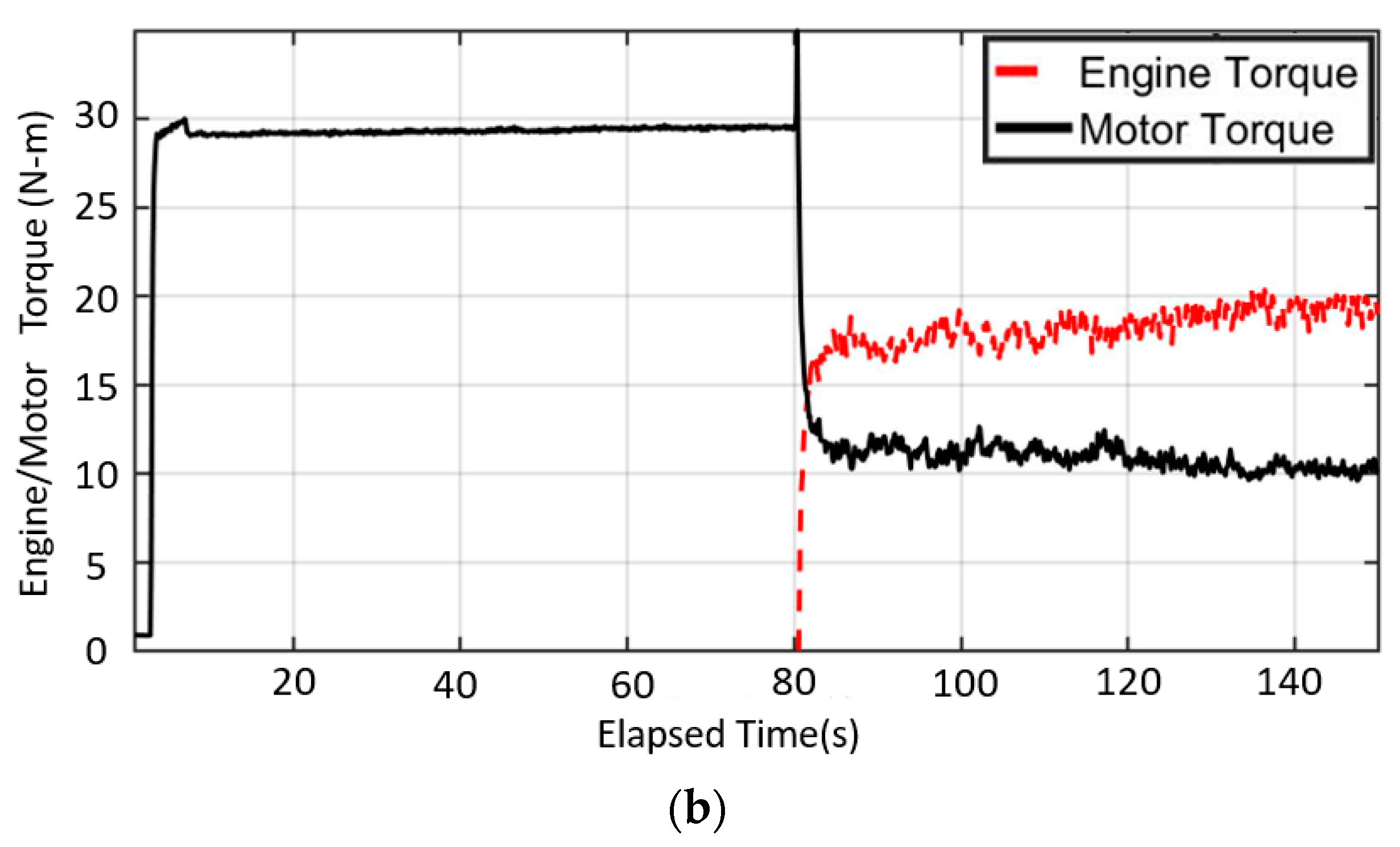
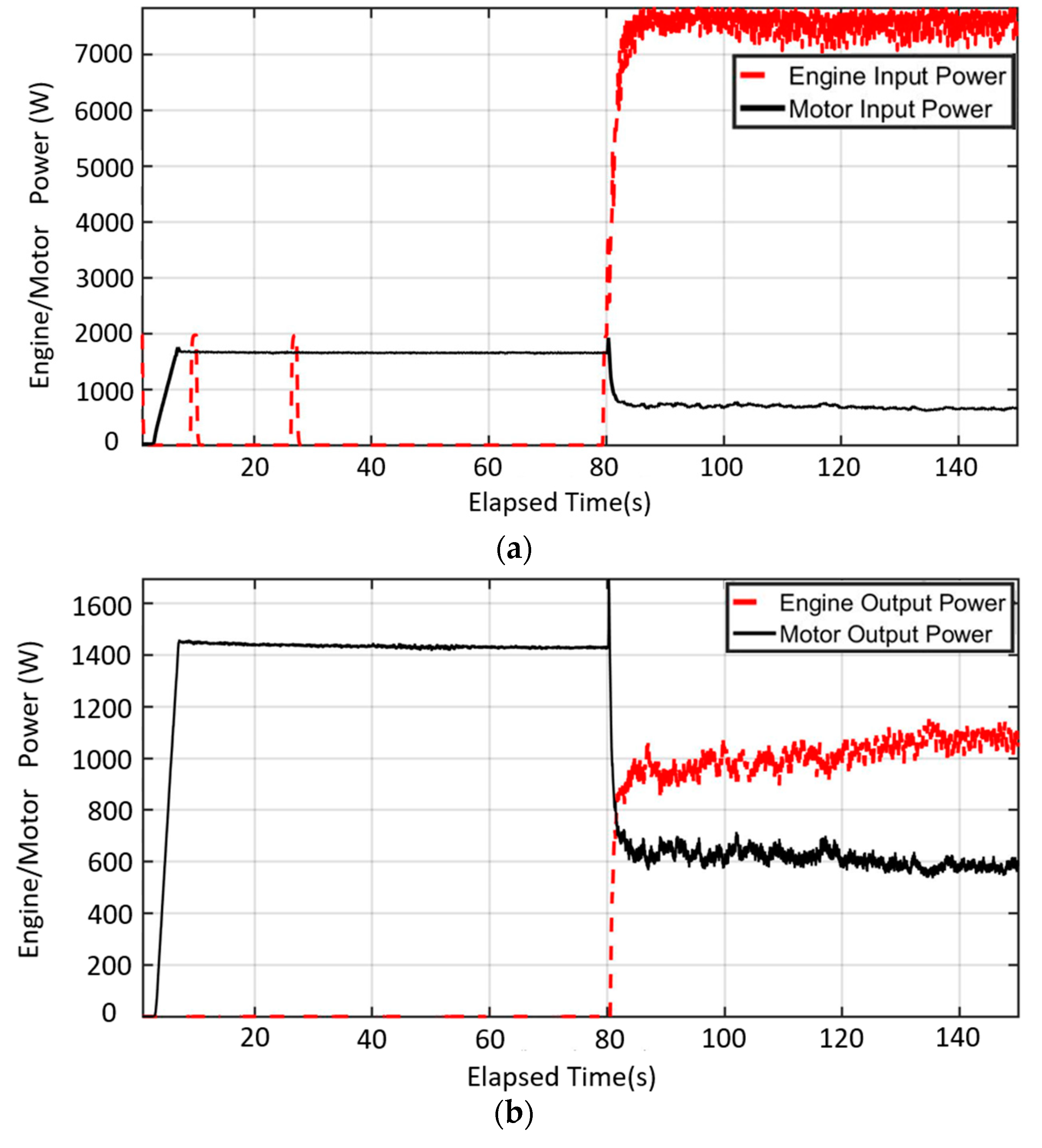
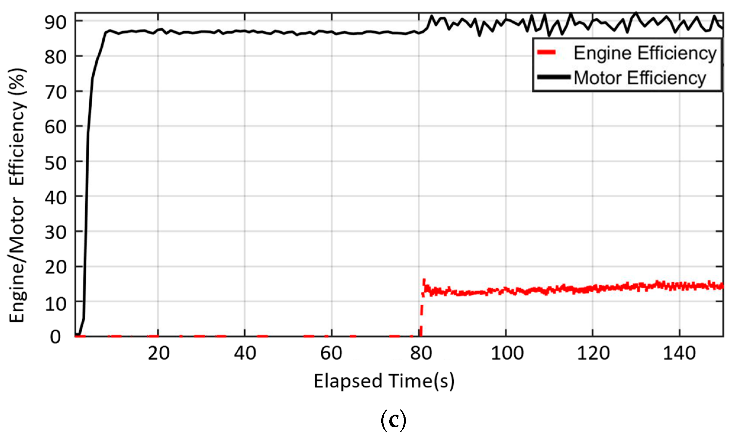
4.1. Engine/hub Motor Hybrid Mode

As mentioned in Mode 4 in Table 1, the speed and torque are shown in Figure 10. In Figure 10a, the hub motor starts to accelerate at the third second, and the speed reaches 470 rpm at the 7.2th second. The engine starts to activate from the idle and the C1 is on at the 80.5th second. The hybrid power raises the rotational speed to 510 rpm. Note that because of the engine idle, though the C1 is off in the beginning, the engine speed sensor still measures the temporary engine speed. For the output torque, the hub motor torque rises to 29 N-m at the third second. After C1 is engaged, the motor torque decreases to 11 N-m. Contrarily, the engine torque rises to 17.5 N-m to maintain the gross output torque to the brake.
In order to evaluate the efficiency of the hybrid system, the input and output power of dual power sources are calculated based on Figure 1 and Figure 2. The hub motor input electric power rises to 1740W at the 7th second in Figure 11a. As the engine clutch is engaged, the electric input power decreases to 770W at the 80.5th second. Meanwhile, the input power of the engine fuel rises to 7300W. In Figure 11b, the mechanical output power of the hub motor is 1450W. The motor power decreases to 600, as the engine is on and the C1 is engaged. Meanwhile, the output engine power rises to 620W. According to Figure 11a,b, the efficiencies of dual power sources are calculated, as shown in Figure 11c. For the hub motor, the efficiency is 87% at the third second, while 89% at the 80.5th second as the engine clutch is on. For the engine, the efficiency is 13% after the 80th second.

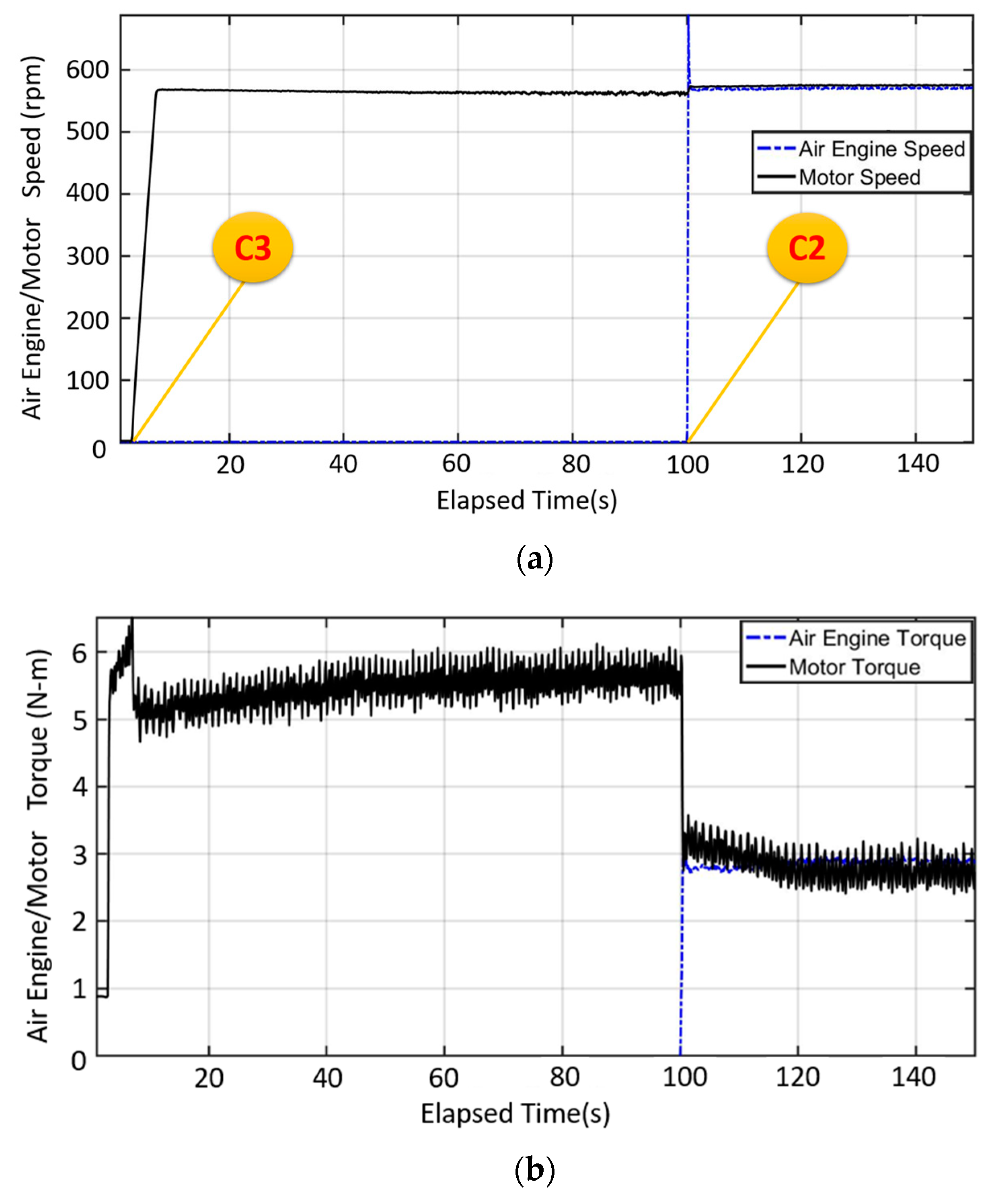
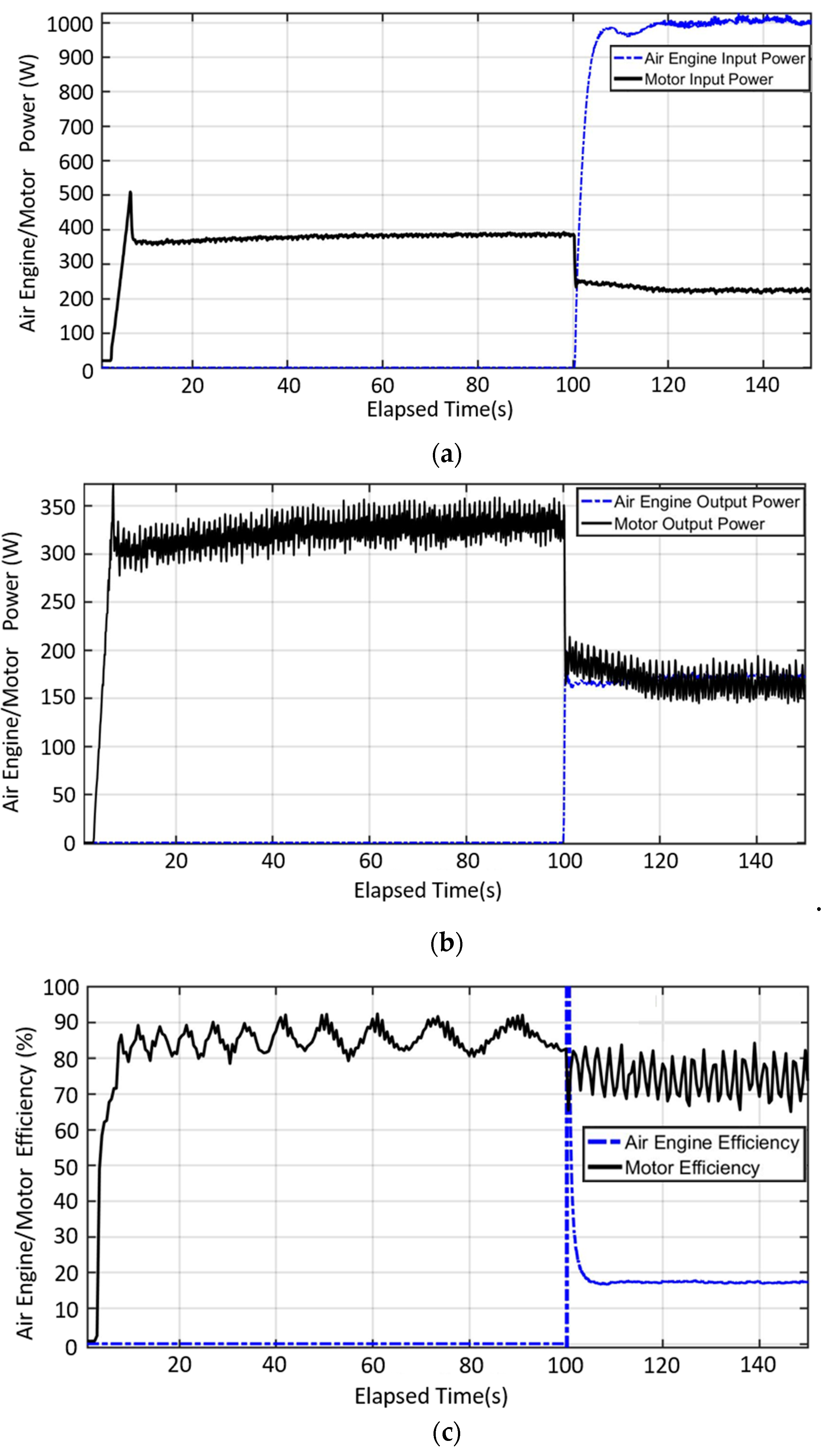
4.2. Hub Motor/Air Engine Hybrid Mode

As described in Mode 6 in Table 1, the speed and torque are shown in Figure 12. From Figure 12a, the hub motor activates at the third second, and the speed reaches 566 rpm. Next, the air engine starts to operate after the 100th second as C2 is engaged. The two power devices reach the same speed. For the output torque, the hub motor torque rises to 6.45 N-m at the seventh second and then decreases to 5.5 N-m. After C2 is engaged, the motor torque decreases to 3 N-m. Meanwhile, the air engine torque rises to 2.8 N-m to maintain the gross output torque to the brake.
For the input and output power, they are calculated based on Figure 2 and Figure 3. The hub motor input electric power rises to 508W at the seventh second and then decreases to 365W in Figure 13a. As the air engine C2 is engaged, the input hub motor power decreases to 240W at the 100th second. Meanwhile, the input power of the air engine increases to 960W. In Figure 13b, the mechanical output power of the hub motor rises to 371W and then to 320W. The motor power decreases to 180W at the 100th second. Meanwhile, the output air engine power is 165W. According to Figure 13a,b, the efficiencies are calculated, as shown in Figure 13c. For the hub motor, the efficiency is approximately 85% at the 7th second. For the air engine, the reason why the efficiency exceeds 100% is because that the motor drives the air engine initially at the 100th second. The air engine efficiency then drops to 17.5% after the 101th second.

4.3. Engine/Air Engine Hybrid Mode

As described in Mode 5 in Table 1, the variations of speed and torque are shown in Figure 14. From Figure 14a, the engine speed increases from the idle at the 28.5th second, and the speed reaches 850 rpm at the 40th second. The C2 is engaged at the 100th second, where the final steady-state speed reaches 925 rpm. For the output torque in Figure 14b, the engine torque rises to 18.5 N-m at the 40th second and then decreases to 16.7 N-m at the 100th second. After the C2 is engaged, the air engine torque increases to 3.6 N-m.
For the power flows, they are calculated based on Figure 1 and Figure 3. The engine input fuel power gradually increases to 11000W at the 28.5th second, while the air engine power increases to 3000W at the 100th second. In Figure 15b, the mechanical output power of the engine increases to 1600W and then gradually decreases to 1450W at the 100th second. The assistant steady-state air engine power is 320W. Figure 15c shows that the engine efficiency is 15% at the 28.5th second, while it slightly decreases to 14% after the 100th second. For the air engine, the efficiency reaches 100+% is due to the sudden engine power input, and it drops to 10% within two seconds.

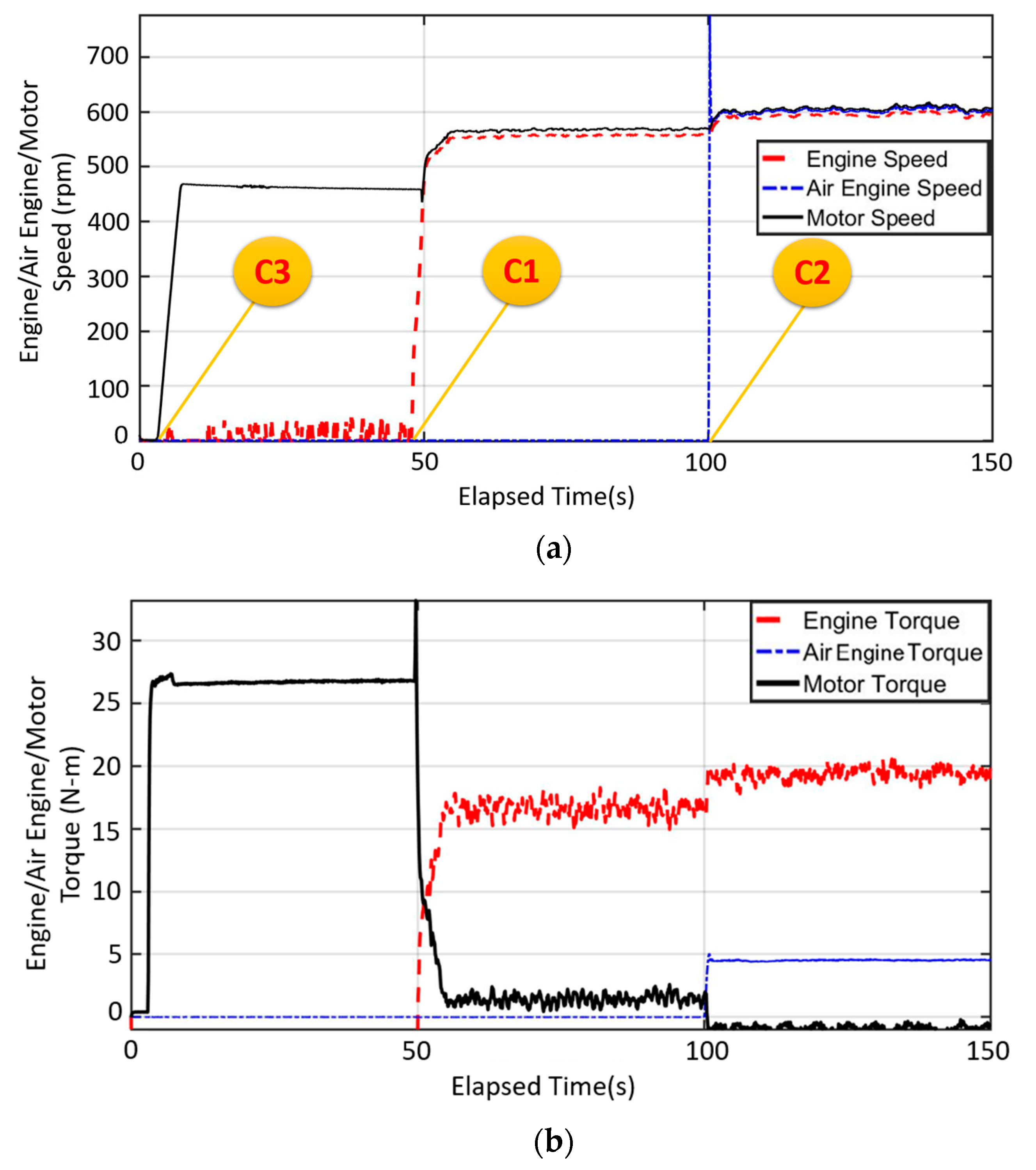
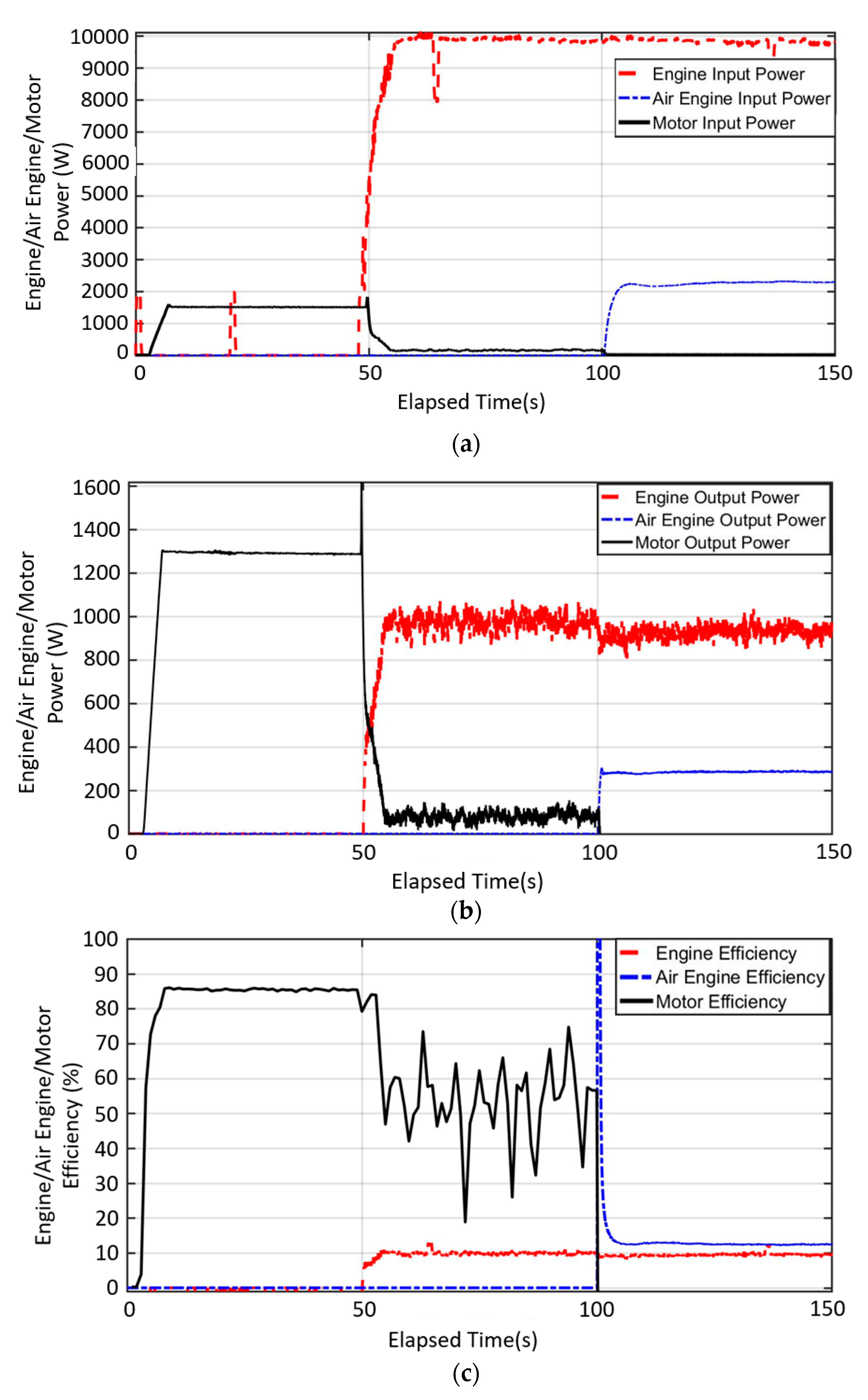
4.4. Engine/Hub Motor/Air Engine Hybrid Mode

In order to demonstrate the three-power-source mode, the activation sequence is from the hub motor for the quick acceleration, then to the engine for the range extension, and finally the air engine for the power assistance. In Figure 16a, the hub motor speed increases to 466 rpm at the fourth second, 550 rpm at the 50th second, and 600 rpm at the 100th second due to the engagement of three clutches from C3, C1, to C2, respectively. For the torque outputs, the hub motor torque starts at the third second, while reaches 27 N-m at the 7.1th second. At the 50th second, the torque drops to 1.5 N-m as C2 is on, while 0 N-m at the 100th second. The air engine torque starts from 5 N-m and then to 4.5 N-m at approximately the 100th second.
For the input power in Figure 17a, the electric power of the motor is 1567W at the 7.1th second, while it drops to 150W at the 50th second. The engine starts to provide the fuel power at the 45th second and reaches 9900W at the 55th second. The assistant power from the input compressed air of the air engine rises to 2200W at the 104th second. For the output power in Figure 17b, the mechanical power of the hub motor rises to 1300W at the eighth second. At the 50th second, as C1 is on for the engine, the motor power decreases to 80W, while the motor stops as the air engine is on at the 100th second. The engine mechanical power is 1000W at the 54th second, and it slightly decreases to 950W when the pneumatic energy is provided at the 100th second. The air engine delivers 280W at the same time. For the efficiencies, the hub motor efficiency increases to 86% at the eighth second, and a serious vibration occurs at the 50th second (averagely 60%) because of the influences of the engine power. The air engine majorly provides the efficiency approaches 0% at the 100th second due to the gross power. The efficiency of the engine after the 50th second is nearly 10% with the CVT transmission loss. For the air engine efficiency, it exceeds 100% due to the input power from the engine, while it then stabilizes to 12.9%.

5. Conclusions

This study established a mechatronics platform for a seven-mode three-power-source powertrain system. The “all-in-one” concept significantly reduces the cost and R&D resources for the performance assessment of various hybrid power systems. The research contributions are summarized, as follows:
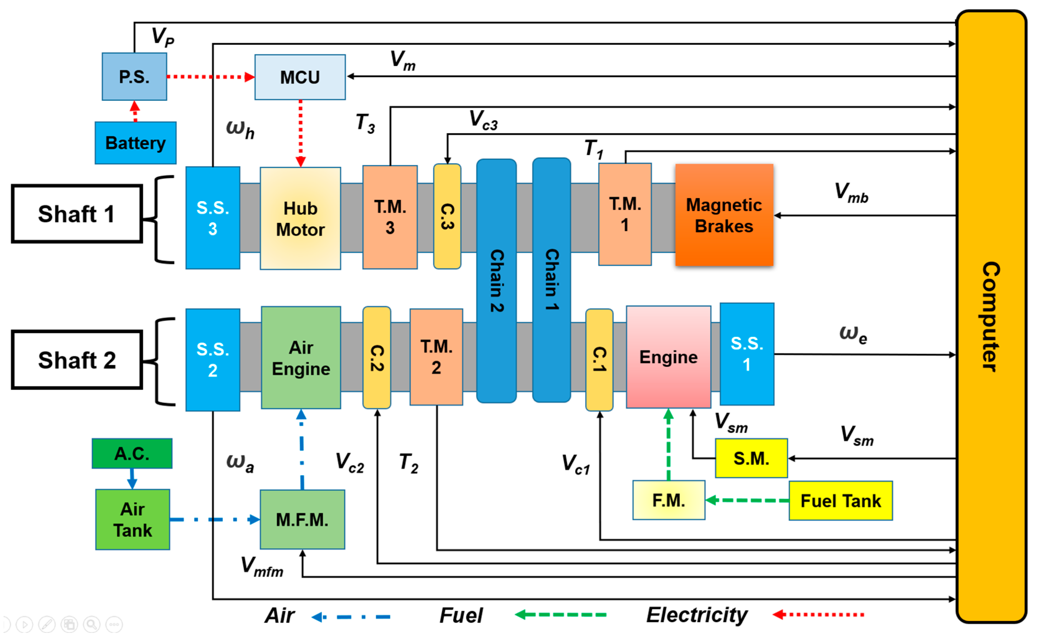
  • Innovative all-in-one mechatronics system: a 125 c.c. SI engine, a 1.5kW hub motor, a 1kW air engine, and a outload simulation system are combined on two transmission shafts where three e-clutches and two chain belts deliver the power flow.
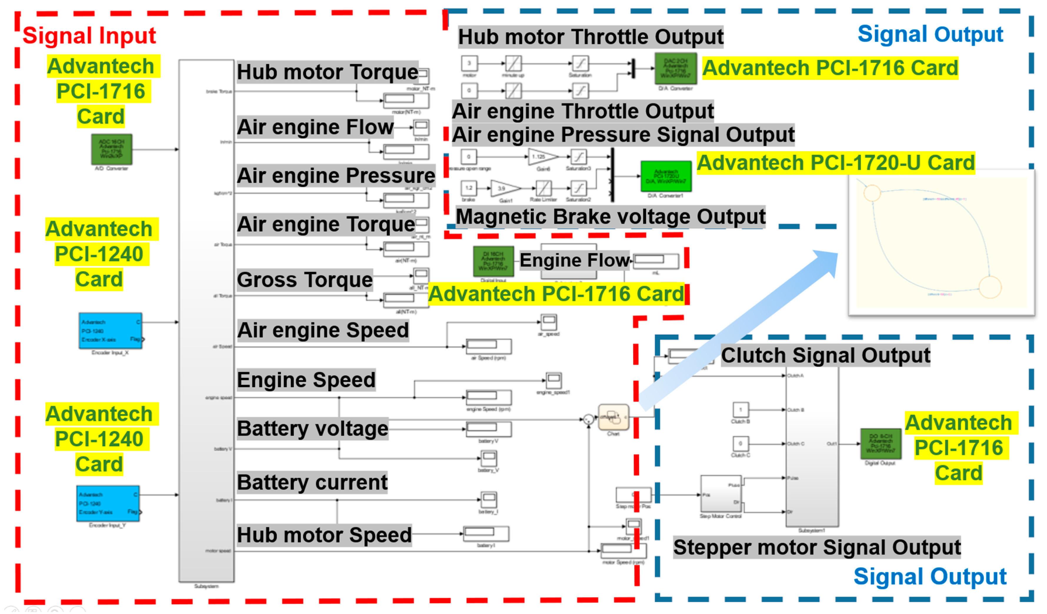
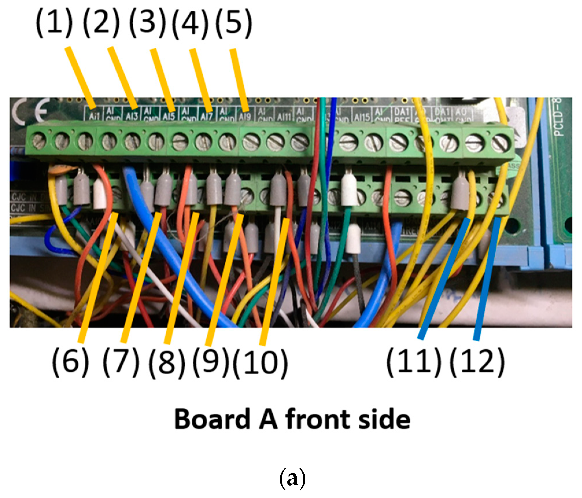
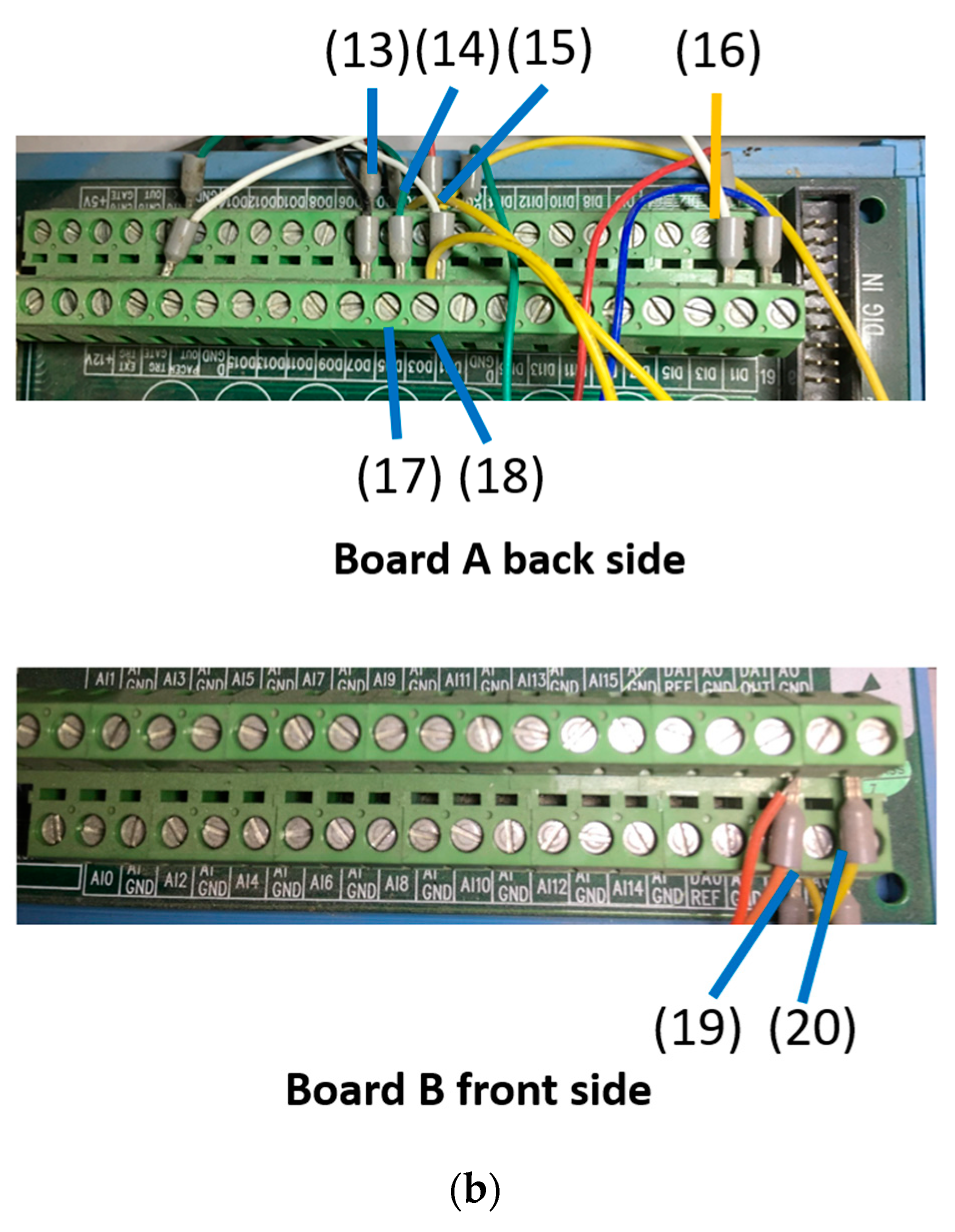
  • The integration of control, harness, and signals: on the Matlab/Simulink environment, it receives the measured signals and sends the control commands to actuators (throttles and the MCU). The rule-based control of three e-clutches, three single-source modes, three dual-source modes, and one three-source mode (3+3+1) can be conducted.
  • Four mode demonstration: the results show that four modes, including three dual-source modes and one three-source mode, were successfully operated. The torque and speed, input/output power, and the efficiencies can be recorded and analyzed. For engine/hub motor mode, the hub motor activates and accelerates first (C3 on), and then the engine starts (C1 on). The hub motor efficiency ranged from 87–89%, while 13% for the engine. For the hub motor/air engine mode, the major power-hub motor starts first (C3 on), and then the air engine (C2 on). The hub motor efficiency varies from 70% to 90%, while 17.5% for the air engine. For the engine/air engine mode, the main power-engine lunches first (C1 on) and the air engine (C2 on), where the engine efficiency is nearly 15% while 10% for the air engine. For the three-power-source mode, the hub motor provides large torque in the beginning (C1 on), then the engine starts as the main power, while the air engine is for the power assistance. The motor efficiency is 86%, and 10% and 12.9% for the engine and the air engine, respectively. The above results prove the high flexibility of power combination, and this research provides a good platform for the research of hybrid powertrains and energy control.
This novel seven-mode hybrid powertrain platform will be equipped with other power/energy sources and new-type transmissions in the future. The advanced control and energy management algorithms will also be further implemented.

Author Contributions

Conceptualization, Y.-H.H. and C.-H.C.; methodology, Y.-H.H., C.-H.C. and H.-Y.C.; software, H.-Y.C. and J.-J.X.; validation, H.-Y.C. and J.-J.X. and C.-H.W.; formal analysis, H.-Y.C. and C.-H.W.; writing—original draft preparation, H.-Y.C., J.-J.X., and C.-H.C.; writing—review and editing, Y.-H.H., C.-H.C.; supervision, Y.-H.H. All authors have read and agreed to the published version of the manuscript.

Funding

This research received funding from the Ministry of Science and Technology of the Republic of China, Taiwan.

Acknowledgments

The authors would like to thank the Ministry of Science and Technology of the Republic of China, Taiwan, for financial support for this research under Contract No. MOST 108-2628-E-003-001-MY3.

Conflicts of Interest

The authors declare no conflict of interest.

References

  1. Wang, X.I.; He, H.W.; Sun, F.C.; Zhang, J.L. Architectures of Planetary Hybrid Powertrain System: Review, Classification and Comparison. Energies 2020, 13, 329. [Google Scholar] [CrossRef] [Green Version]
  2. Chen, X.; Hu, G.G.; Guo, F.; Ye, M.Q.; Huang, J.Y. Switched Energy Management Strategy for Fuel Cell Hybrid Vehicle Based on Switch Network. Energies 2020, 13, 247. [Google Scholar] [CrossRef] [Green Version]
  3. Hung, Y.H.; Tung, Y.M.; Li, H.W. A real-time model of an automotive air propulsion system. Appl. Energy 2014, 129, 287–298. [Google Scholar] [CrossRef]
  4. Bagwe, R.M.; Byerly, A.; Santos, E.C.D.; BenMiled, Z. Adaptive Rule-Based Energy Management Strategy for a Parallel HEV. Energies 2019, 12, 4472. [Google Scholar] [CrossRef] [Green Version]
  5. Wang, X.I.; He, H.W.; Sun, F.C.; Zhang, J.L. Application Study on the Dynamic Programming Algorithm for Energy Management of Plug-in Hybrid Electric Vehicles. Energies 2015, 8, 3225–3244. [Google Scholar] [CrossRef] [Green Version]
  6. Chung, C.T.; Hung, Y.H. Performance and energy management of a novel full hybrid electric powertrain system. Energy 2015, 89, 626–636. [Google Scholar] [CrossRef]
  7. Khaligh, A.; Li, Z. Battery, ultracapacitor, fuel cell, and hybrid energy storage systems for electric, hybrid electric, fuel cell, and plug-in hybrid electric vehicles: State of the art. IEEE Trans. Veh. Technol. 2010, 59, 2806–2814. [Google Scholar] [CrossRef]
  8. Tate, E.; Harpster, M.; Savagian, P. The Electrification of the automobile: From conventional hybrid, to plug-in hybrids, to extended-range electric vehicles. SAE Int. J. Passeng. Cars-Electron. Electr. Syst. 2009, 1, 156–166. [Google Scholar] [CrossRef] [Green Version]
  9. Wang, Y.; Song, X.; Sun, Z. Hybrid powertrain control with a rapid prototyping research platform. In Proceedings of the IEEE 2011 American Control Conference, San Francisco, CA, USA, 29 June–1 July 2011; pp. 997–1002. [Google Scholar]
  10. Ye, X.; Jin, Z.; Liu, B.; Chen, M.; Lu, Q. Design and application of parallel hybrid vehicle simulation platform. In Proceedings of the IEEE Vehicle Power and Propulsion Conference, Hangzhou, China, 17–20 October 2010; pp. 1–5. [Google Scholar]
  11. Timmermans, J.; Van Mierlo, J.; Lataire, P.; Van Mulders, F.; McCaffree, Z. Test platform for hybrid electric power systems: Development of a HIL test platform. In Proceedings of the IEEE European Conference on Power Electronics and Applications, Aalborg, Denmark, 2–5 September 2007; pp. 1–7. [Google Scholar]
  12. Padian, S.R.; Takemura, F.; Hayakawa, Y.; Kawamura, Y.S. Control performance of an air motor-can air motors replace electric motors? In Proceedings of the IEEE International Conference on Robotics & Automation, Detroit, MI, USA, 10–15 May 1999; pp. 518–524. [Google Scholar]
  13. Hwang, Y.R.; Shen, Y.D.; Jen, K.K. Fuzzy MRAC controller design for vane-type air motor systems. J. Mech. Sci. Technol 2008, 22, 497–505. [Google Scholar] [CrossRef]
  14. Wang, J.; Yan, L.; Luo, X.; Mangan, S.; Derby, J.W. Mathematical modeling study of scroll air motors and energy efficiency analysis—Part I. IEEE/ASME Trans. On Mech. 2011, 16, 112–121. [Google Scholar] [CrossRef]
  15. Wang, J.; Yan, L.; Luo, X.; Mangan, S.; Derby, J.W. Mathematical modeling study of scroll air motors and energy efficiency analysis—Part II. IEEE/ASME Trans. On Mech. 2011, 16, 122–132. [Google Scholar] [CrossRef]
  16. Huang, K.D.; Tzeng, S.C. Development of a hybrid pneumatic-power vehicle. Appl. Energy 2005, 80, 47–59. [Google Scholar] [CrossRef]
  17. Huang, K.D.; Tzeng, S.C.; Ma, W.P.; Chang, W.C. Hybrid pneumatic-power system which recycles exhaust gas of an internal-combustion engine. Appl. Energy 2005, 82, 117–132. [Google Scholar] [CrossRef]
  18. Huang, K.D.; Tzeng, S.C.; Chang, W.C. Energy-saving hybrid vehicle using a pneumatic-power system. Appl. Energy 2005, 81, 1–18. [Google Scholar] [CrossRef]
  19. Shen, Y.T.; Hwang, Y.R. Design and implementation of an air-powered motorcycle. Appl. Energy 2009, 86, 1105–1110. [Google Scholar]
  20. Hung, Y.H.; Chen, J.H.; Wu, C.H.; Chen, S.Y. System design and mechatronics of an air supply station for air-powered scooters. Comput. Electr. Eng. 2016, 54, 185–194. [Google Scholar] [CrossRef]
Figure 1. System components of the three-power-source hybrid platform.
Energies 13 02104 g001
Figure 2. Scheme of the seven-mode three-power-source experimental platform.
Energies 13 02104 g002
Figure 3. Energy (Power) flow of the seven modes: (a) Single-source (engine, motor, air engine) mode; (b) Dual-source (engine/motor, motor/air engine, engine/air engine) mode; and, (c) Triple-source mode.
Energies 13 02104 g003
Figure 4. Matlab/Simulink input/output control block diagram.
Energies 13 02104 g004
Figure 5. Key components of engine power system.
Energies 13 02104 g005
Figure 6. Key components of traction motor power system.
Energies 13 02104 g006
Figure 7. Key components of air engine power system.
Energies 13 02104 g007
Figure 8. Three-power-source experimental platform: (a) top view; (b) side view.
Energies 13 02104 g008aEnergies 13 02104 g008b
Figure 9. I/O communication interface for (a) Board A; (b) Board B.
Energies 13 02104 g009aEnergies 13 02104 g009b
Figure 10. Engine/hub motor hybrid mode: (a) speed; (b) torque.
Energies 13 02104 g010aEnergies 13 02104 g010b
Figure 11. Engine/hub motor hybrid mode: (a) input power; (b) output power; and, (c) efficiency.
Energies 13 02104 g011aEnergies 13 02104 g011b
Figure 12. Hub motor/air engine hybrid mode: (a) speed; (b) torque.
Energies 13 02104 g012
Figure 13. Hub motor/air engine hybrid mode: (a) input power; (b) output power; and, (c) efficiency.
Energies 13 02104 g013
Figure 14. Engine/air engine hybrid mode (1): (a) speed; (b) torque.
Energies 13 02104 g014
Figure 15. Engine/air engine hybrid mode: (a) input power; (b) output power; and, (c) efficiency.
Energies 13 02104 g015
Figure 16. Engine/motor/air engine hybrid mode: (a) speeds; (b) torque.
Energies 13 02104 g016
Figure 17. Engine/motor/air engine hybrid mode: (a) input power, (b) output power; and, (c) efficiency.
Energies 13 02104 g017
Table 1. Relationship of the seven modes and the clutch control.
ModelClutch1Clutch2Clutch3Switch Condition
Hub MotorOFFOFFON--
EngineONOFFOFF--
Air EngineOFFONOFF--
Engine + Hub MotorONOFFON(1) Hub motor on
(2) Clutch 1 on when engine speed reaches motor speed
Engine + Air EngineONONOFF(1) Engine on
(2) Clutch 2 on when air engine speed reaches engine speed
Hub Motor + Air EngineOFFONON(1) Hub motor on
(2) Clutch 2 on when air engine speed reaches hub motor speed
Engine + Hub Motor + Air EngineONONON(1) Hub motor on
(2) Clutch 1 and 2 on when engine and air engine speeds reach motor speed

