Abstract
To deal with the technical challenges of renewable energy penetration, this paper focuses on improving the grid voltage and frequency responses in a hybrid renewable energy source integrated power system following load and generation contingency events. A consolidated methodology is proposed to employ a battery energy storage system (BESS) to contribute to voltage regulation through droop-type control and frequency regulation by assimilated inertia emulation (IE) and droop-type control. In addition, a novel frequency-dependent state-of-charge (SOC) recovery (FDSR) is presented to regulate BESS power consumption within the FDSR constraints and recharge the battery during idle periods whenever needed. The efficacy of the proposed BESS controller is demonstrated in an IEEE-9 bus system with a 22.5% photovoltaics (PV) and wind penetration level. The simulation results obtained manifest the satisfactory performance of the proposed controller in regulating simultaneous voltage and frequency in terms of lower rate of change of frequency and better frequency nadir. Furthermore, the proposed FDSR demonstrates its superiority at the time of SOC recovery compared to the conventional approach.
1. Introduction
A large amount of renewable energy sources (RESs), mainly wind and photovoltaic (PV) power plants, has been installed throughout Europe, the USA, and Asia. A European Network of Transmission System Operators for Electricity (ENTSO-E) forecast stated that fossil fuelled conventional power plants (CPPs) are closing down following increased RES penetration in the grid [1]. With the replacement of CPPs by fundamentally intermittent wind and PV sources, several inevitable technical challenges are being introduced that can have a significant impact on the stability and security of the power system. The conventional synchronous generators inherently provide inertial response to frequency deviation and can participate in load-frequency control (LFC) according to their droop characteristics, given that sufficient spinning reserves are accessible. Therefore, increased penetration of RESs significantly reduces system inertia as RESs have the limitation of providing fundamental inertial and primary frequency control (PFC) response. This eventually affects the rate of change of frequency (ROCOF) and the maximum/minimum frequency limit during post-contingency periods, and therefore, the provision of frequency control becomes a challenging task.
The smart grid-oriented future power system with dominant infiltration of power electronics has led to a significant amount of research on emulating the behaviour of synchronous machines by exploiting the control mechanism of the power electronics converter at RES farms [2]. Different control strategies are proposed to provide grid frequency control including under-frequency load-shedding [3], regulating DC voltage in HVDC [4], and demand-side management [5]. Typically, RES plants are regulated to produce the maximum output power at a given wind speed and solar radiation. The research conducted by Engleitner et al. [5] proposed that wind farms can take part in regulating grid frequency through the use of their stored kinetic energy. To some extent, PV systems can also demonstrate frequency response capability [6]. However, such control approaches require curtailing power generation at their terminal, which is not desirable. Moreover, the implicit weather-dependent nature of RESs makes it unreliable to rely on adopting such control approaches. A new research trend of an electric vehicle (EV) acting as a power reserve to regulate frequency was proposed by Aliabadi et al. [7] and Liu et al. [8]; nevertheless, the vehicle-to-grid infrastructure to control grid frequency is not yet accessible. Moreover, different energy storage technologies are available to contribute both inertial [9] and primary frequency control [10].
The power-frequency droop control of BESS has been reported to have significant improvement in primary frequency response [11,12]. Li et al. [13] demonstrated that a droop-controlled hybrid storage system suppressed significant frequency oscillations and offered robust stability responses. Virtual inertia offers an added benefit to the system dynamics by delivering the required power imbalance. An inertia emulation (IE) performance analysis of an energy storage system (ESS) [14] and BESS [9] in a microgrid (MG) was demonstrated to deliver robust frequency stability. A combination of BESS for PFC and an ultra-capacitor for IE was proposed by Fini and Golshan [15] to improve the frequency stability of an MG. Different optimal energy storage methods have been proposed to enhance frequency variation for the required IE [16] and PFC in an MG using battery overloading features [17]. The research by Toma et al. [18] considered BESS to provide virtual inertia and PFC in a two-area power system considering 100% renewable generation. However, the battery state-of-charge (SOC) was completely overlooked in the earlier studies [14,15,18,19,20]. ESS provides IE and PFC to regulate grid frequency with high wind penetration [20]. Fast acting BESS is utilized for IE and PFC to participate in unit-commitment and improve frequency dynamics under contingencies [21]. The optimal sizing of BESS considering the BESS contribution as IE and PFC was presented in [22]. The study by Brogan et al. [23] demonstrated that improvements in frequency nadir and ROCOF were visible when BESS was activated with less time delay and high BESS power input following the changes. Nevertheless, all the aforementioned studies of IE and IE with PFC were based on active power regulation of BESS and did not provide any insight into the voltage regulation capability of BESS. A charge/discharge management of BESS was proposed by Zeraati et al. [24] via a droop control method in order to regulate distribution network voltage with high PV penetration.
In [25], BESS was proposed to regulate voltage and frequency in an MG. Nonetheless, battery SOC was considered for the droop component only. As demonstrated by Alhejaj and Longatt [26], battery SOC discharge is inversely related to the BESS inertia constant; hence, ignoring SOC for the inertia component is an inaccurate assumption in designing BESS for IE and PFC. An autonomous SOC recovery was proposed in [27] that suggested the regulation of the terminal voltage of the super-capacitor (SC) to maintain SOC defined constraints of SC from the battery. A similar SOC recovery was proposed by Xiao et al. [28] for voltage regulation and SOC recovery as long as the power capacity of energy storage devices was available. Nevertheless, these studied did not provide any insight into the impact of SOC recovery on the frequency of the grid. On the contrary, the study by Zhu and Zhang [29] proposed an SOC recovery strategy that could minimize the penalty costs due to the failure of frequency regulation. Variable SOC recovery strategies were proposed by Datta et al. [30] depending on the value of the charging current. However, the impact of SOC management on the performance of the controller and grid frequency was not considered by Zhu and Zhang [29] and by Datta et al. [30].
This paper therefore proposes an IE-and PFC-regulated BESS to achieve enhanced frequency dynamics in a power system with high shares of non-synchronous renewable generation. In addition, the droop control is selected to regulate reactive power and enhance the voltage dynamics. Hence, the main contributions of this paper include: (1) the proposed combined inertia- and droop-controlled frequency regulation and droop-controlled voltage regulation, which have not been studied in the earlier literature; (2) a novel frequency-dependent SOC recovery (FDSR) strategy to ensure sufficient SOC is available for future events without affecting the grid frequency. The proposed control approach regulates BESS active and reactive power considering BESS operation within the defined SOC constraints when participating in IE ad PFC.
2. System Inertia and Frequency Response
The inertia of rotating masses of synchronous machines and turbines responds to immediate frequency changes, due to power deficit, by regulating power flows (injection/absorption). There are several stages in frequency control following a power imbalance from a contingency event: the inertia response to regulate ROCOF, which is an uncontrolled response, primary control, secondary control, and tertiary control to mitigate frequency deviations, as shown in Figure 1. In the inertia control stage, power imbalance is met by the implicit kinetic energy release of synchronous machines during periods of 0–10 s [14]. PFC takes over this stage, once the controller is activated, mainly during periods of 0–30 s, and stabilizes the frequency to a new steady-state point. Then, the secondary and tertiary control recovers frequency to the non-operating frequency boundary if required, and the feature is available for a duration of 30 s–30 min [31]. The minimum grid frequency response followed by power imbalance is influenced by the deployment and the intensity of virtual inertia control and PFC, which depends on the available physical inertia and power/energy regulation capability of the system. The overall system inertia constant was defined in [32] as:
where is the total system inertia and is the total stored kinetic energy of all rotating machines with their rotational speed (), moment of inertia (J), and rated base power of the system ().
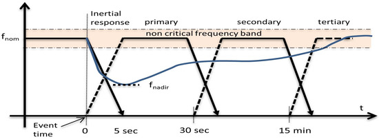
Figure 1.
Frequency response stages by the European Network of Transmission System Operators for Electricity (ENTSO-E) [1].
The power imbalance () during a contingency is determined by Equation (2):
where and are total generated and total load power, respectively. Substituting the value of J from (2) into (1), the swing equation describing the relationship of system inertia () and ROCOF due to power imbalance can be defined as in (3) [32]:
where is the nominal system frequency. It can be observed that ROCOF (df/dt) is inversely related to the system inertia, which implies that with a lower inertia value, the grid has a weaker frequency response capability during the abrupt changes in the power balance between power generation and demand and results in higher ROCOF.
At present, the grid code defines the ROCOF value for the Australian Energy Market Operator (AEMO) and ENTSO-E to be ≤0.5 Hz/s [33,34]. A faster ROCOF may activate protection relays and may cause tripping of generators [33]. On the other hand, rapid initial ROCOF may contribute a large frequency deviation, which can result in generator trip and load shedding [33]. In the Australian National Electricity Market (NEM), the maximum allowable frequency deviation in the post-fault condition is 50 ± 0.5 Hz for a load event and generation event with 50 ± 0.15 Hz as non-critical frequency operating ranges [35].
Synchronous inertia plays a fundamental role in minimizing the faster changes of frequency (df/dt). Synchronous machines respond to power deficit instantly by releasing kinetic energy as they are coupled with the grid frequency. On the contrary, generators on renewable farms are connected to the grid via a power electronics interface; hence intrinsically, they are not providing inertia response as they are decoupled from the grid frequency. Therefore, with increased penetration of asynchronous renewable generation, the power system has lower inertial response capability.
3. Proposed IE and Droop-Regulated BESS Control Schemes
The proposed BESS structure and its control system are discussed in this section. The control schemes regulate power flow between the battery and the grid via a voltage source converter (VSC). The measurements for voltage and frequency controllers are taken locally to control BESS operation. BESS regulates active and reactive power independently by governing its current controller in the d and q axes, and the total power is delimited by BESS converter capacity.
3.1. Frequency Controller for IE and PFC
BESS contributes towards frequency regulation by altering active power through the point of common coupling (PCC). At PFC, reduced system inertia affects power-frequency droop and thus influences the stability of the power system. Figure 2 illustrates the block diagram of the frequency controller to provide IE and PFC. The goal of the proposed frequency controller is to enhance the damping of frequency oscillations and reduce the value of ROCOF and frequency deviation. BESS is designed to emulate the behaviour of a conventional synchronous generator and provide both the inertial response and primary frequency control.
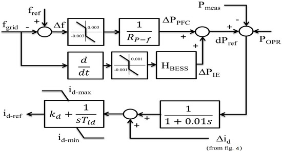
Figure 2.
Block diagram of BESS for the inertia emulation (IE)- and primary frequency control (PFC)-regulated frequency controller.
The expression of the suggested frequency controller can be written as in (4):
where is the total BESS output power reference and and are the changes in BESS active power output based on power-frequency droop characteristics and inertial response capability following the variation in grid frequency respectively and can be expressed as in (5) and (6):
where (pu) is the frequency deviation resulting from a disturbance and calculated as the difference between the reference frequency () and the grid frequency (), is the power-frequency droop value, and is the BESS inertia constant. The positive and negative values of define BESS power injection and absorption, respectively. in (5) specifies the demand of BESS active power adjustment in response to frequency error. The deadband restricts BESS operation for any minor frequency changes and within the grid defined inactive region. The PFC feature is activated if the actual frequency differs by MHz from the nominal value according to NEM criteria [35]. The BESS power is regulated linearly with the variation of frequency error, and the droop value is selected as 0.006 pu in order to activate the nominal BESS power for the frequency deviation of MHz. BESS operates at its maximum rated power when frequency deviation exceeds MHz.
The changes in active power during inertial response are regulated by the derivative of frequency error and the BESS inertia constant as in (6). The value of the inertia constant controls the sensitivity of the BESS controller according to the changes in ROCOF value. Theoretically, can be infinite as the physical concept of limiting the inertia constant is not applicable for BESS. However, the inertia constant value defines the intensity of active power participation, i.e., an increased value generates increased BESS power output, as mentioned in [26]; therefore, the value needs to be determined according to the capacity of the BESS converter. Hence, considering an amalgamated application, the value of was selected as 20 s, which defines the activation of nominal BESS active power for a total of 0.15 Hz/s. The inertial deadband value was selected as 0.05 Hz/s according to [22]. As the deadband for inertial response is smaller than droop response, BESS inertial power is activated for a small deviation in system frequency. Although Duckwitz and Fischer [36] presented that a certain delay may be essential in the control chain in order to avoid control instability when synthetic inertia (i.e., df/dt) control is performed, this study considered no delay for df/dt as in the studies [22] proposed by Knap et al. and [25] proposed by Serban and Marinescu.
The frequency fluctuations are dealt with by varying BESS active power output in charging, discharging, and inactive modes as shown in (7):
The battery storage operates in charging mode if the grid frequency is higher than the reference frequency and in discharging mode if the reference frequency is higher than the grid frequency, considering the SOC of the battery is usable as per the defined battery operating range. The battery can be charged when BESS remains in the inactive region. A low-pass filter is used to filter out the noise in the BESS active power reference. The error between the active power reference and active power output at BESS AC terminal generates updated active current reference in the d axis. The difference of the charge controller input and output as is added with the d axis current reference. P is the external power reference input by the operator.
3.2. Voltage Controller
The grid voltage is affected by the penetration of inverter-based RESs. As BESS can regulate active and reactive power separately, it can be easily utilized to draw/inject reactive power. The voltage control can be accomplished by regulating reactive power sharing according to conventional reactive power-voltage (Q-V) droop. The block diagram of the proposed voltage controller is shown in Figure 3. The figure shows how the reactive power reference is generated in response to the changes in voltage at the BESS AC terminal. Q is the external power reference input by the operator. The tracking error is used as an input to the PI controller.
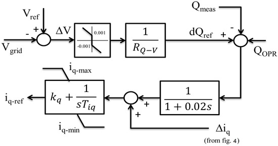
Figure 3.
Block diagram of the BESS voltage controller.
The voltage droop controller can be expressed as in (8):
where is the difference between voltage reference (pu) at steady state and grid voltage (pu) and defines the reactive power reference according to the Q-V droop characteristics. is the measure of reactive power intensity, which was selected as 10, defining the nominal reactive power activation for a voltage deviation of 0.1 pu with a voltage tolerance of pu. The lower slope for the reactive power-voltage drop is preferred to avoid overloading of BESS.
BESS absorbs/injects reactive power according to three level structures as shown in (9):
A low-pass filter is used to filter out the noise in the BESS reactive power reference, and the current reference in the q axis is generated using a PI controller. The error between the charge controller input and output as is added with the updated reactive current reference. This reference is calculated from the error of reactive power reference and the reactive power output at the BESS AC terminal that generates the reactive current reference in the q axis. The associated BESS parameters are given in Appendix A. The initial battery SOC was considered as 0.8 pu. As this study focuses on short-term transients, the smaller size of BESS capacity was selected for simulation purposes. The nominal source voltage and the internal resistance of the battery were selected as in [37]. PI parameters were tuned on a trial-and-error basis.
3.3. Proposed FDSR-Based Charge/Discharge Management
The BESS charge/discharge management (BCDM) encompasses coordinated operation between grid demand and accessible BESS power. BESS participates in frequency control by exchanging energy during over-frequency and under-frequency events resulting from power transients. It is worth noting that an effective control strategy is indispensable to avoid unwanted deep discharge and over-charge operation of BESS. The direction of current flow selects the appropriate SOC condition to fulfil and manage battery charge/discharge to deliver the required BESS output if the SOC condition is met. BESS operates in discharging mode if battery SOC is greater than the minimum SOC and charging mode if present battery SOC is less than the maximum SOC. The minimum and maximum battery SOC were selected as 0.2 pu and 1 pu, respectively. Battery SOC changes throughout the power exchanging periods (increase/decrease). Therefore, BESS functions in SOC recovery charging mode if battery SOC drops lower than the threshold or the minimum SOC value according to the conditions specified in (10). However, according to the proposed FDSR, the battery will only be recharged if the grid frequency is equal to or higher than the minimum limit of the nominal frequency limit, i.e., 0.997 pu. This can avoid the deep discharge of the battery and secure BESS availability for the upcoming events without affecting grid frequency stability.
Figure 4 illustrates the battery charging or discharging mechanism, highlighting the various control levels of BESS action. BCDM governs the response of BESS to the changes in frequency controller output and mandatory charging recovery, if applicable.
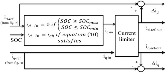
Figure 4.
Block diagram of BESS charge/discharge management.
BCDM determines whether the generated active power reference is executable from BESS according to available and specified SOC operating values. BESS operates in power curtailment mode when the SOC of the battery reaches the defined minimum and maximum range. The overall BESS charge/discharge approach can be defined as in (11):
As the active and reactive power of BESS is limited by its apparent power, a well regulated power allocation is imperative to avoid competition between these two and thus avoid saturation when the grid demands a large amount of active and reactive power at the same time. The current limiter calculates the total BESS current at its output to make sure active and reactive power do not exceed the rated capacity of BESS and can be calculated as shown in Figure 5. The active power is given preference over the reactive power, which can be calculated as in Figure 5a. The reactive power output is limited by the remaining BESS capacity and can be calculated as illustrated in Figure 5b where the value of y can be calculated as in (12).
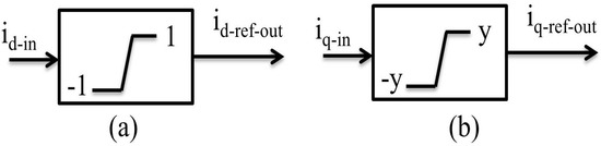
Figure 5.
Active (a) and reactive (b) power calculation at converter output.
3.4. Battery Model and SOC Calculation
Unlike the previous work in [25], SOC is calculated based on the total power output of BESS, which is the proper method of calculating battery SOC in this study. The selected battery model is an equivalent model, which was widely used in the previous studies [38,39,40].
The battery SOC can be calculated as follows:
where is the Coulomb efficiency, is the battery current, is the rated battery capacity, and k is the time of SOC calculation. Furthermore, = at the charging stage and = at the discharging stage, which is 0.98 and one, respectively, as in [41], and the temperature dependency for Coulomb efficiency is not considered in this study.
3.5. Current Controller on the d and q Axes
The current control loop, an internal level control, provides the reference voltage at BESS output (AC side) for regulating the VSC. The input of the current controller is the external control loop generated current reference in the d () and q () axes and the measured d and q axis current from the internal control loop. The phase-locked-loop (PLL) provides the necessary reference phase angle to the d-q transform value in the three phase reference for regulating DC/AC converter.
4. Attributes of the Test System
The performance of the proposed BESS model was investigated on an IEEE 9 bus standard test network, as shown in Figure 6, with 22.5% renewable energy penetration. The synchronous generator G1 was considered as the reference generator. The generators were dynamically modelled as hydro- (G1), gas- (G2), and coal-type (G3) power plants with a capacity of 250 MW, 255 MW, and 230 MW, respectively. All the generators were designed with a turbine governor and automatic voltage regulator (AVR). The connected RES farms at buses 5 and 9 were solar PV-type, whereas at buses 6 and 8, they were doubly-fed-induction generator-based wind-type. The RESs farm was integrated with the grid via a step-up transformer. The BESS was connected to the network via a 0.4/230 kV step-up transformer. The studied model was designed and simulated in Powerfactory, and the renewable generation parameters are given in Appendix A.
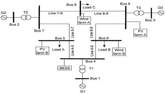
Figure 6.
IEEE 9 bus standard test network with installed BESS and RES. G, generator.
Three case studies were investigated to evaluate the performance of the proposed BESS for IE and PFC and to achieve a grid code compatible outcome. The considered case studies were as follows:
- Case 1: Load change event
- Case 2: Generation event
- Case 3: BESS recharging with FDSR
- Case 4: Single-phase-to-ground fault
BESS was integrated to provide additional system damping and improve the transient response of the system with increased RES penetration.
5. Results and Discussion
The dynamic responses of the proposed BESS were evaluated in a hybrid power system following multiple disturbance scenarios. The performance of the proposed BESS was assessed in accordance with fulfilling the NEM criteria as mentioned in [35].
5.1. Load Change Event
In this section, the objective is to assess BESS efficacy in strengthening the frequency response of the grid following an abrupt change in load demand at a particular bus. A temporary 50% step increase in load demand at Load A (bus 5) was applied during t = 0–0.75 s. The applied transient load event would create frequency oscillations due to temporary imbalances between the electrical and mechanical power of each generator.
Figure 7 depicts that without a BESS, the frequency of generator G1 dropped to a value of 49.416 Hz, which was beyond the grid defined limit (49.5–50.5 Hz) for a load event. Therefore, a 27 MW BESS was incorporated at bus 4 to provide added oscillation damping to the system. The frequency response of generator G1 illustrated in Figure 7 demonstrated that BESS in inertia or droop control mode failed to achieve the minimum allowed frequency value for the load event. However, droop control (49.478 Hz) performed better than the inertial control (49.435 Hz) of BESS in terms of lowest frequency drop. On the contrary, combined IE- and PFC-regulated BESS delivered sufficient damping to the system and recovered the frequency response within the minimum grid frequency periphery (49.518 Hz). The frequency responses of generators G2 and G3 demonstrated similar performance. As BESS was connected at the generator G1 terminal, the improvement in the case of G2 and G3 was not as prominent as G1. The ROCOF values for different scenarios are outlined in Table 1. The aim was to provide the same values of the inertia constant and droop to demonstrate comparative performances in different frequency controller configurations. BESS as IE support showed a higher ROCOF value as the considered inertia constant of BESS was small. It could be observed that there was a noticeable improvement in slowing down the frequency drop, i.e., lowest ROCOF and highest value that defined the effectiveness of the proposed combined control of BESS.
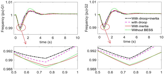
Figure 7.
The frequency (pu) oscillation of generators with the load event.

Table 1.
The frequency results of G1 with the load event.
The response of PCC voltage presented in Figure 8 shows that BESS with combined control performed better than without a BESS and independent of the IE-/PFC-controlled BESS, resulting in lower voltage drop during the load event periods. However, droop control demonstrated a slightly better outcome right after the end of the load event. It is worth noting that as voltage was regulated through droop control only, hence, the voltage responses in all three cases were very similar.
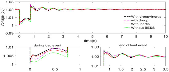
Figure 8.
The voltage (pu) at the point of common coupling (PCC) with the load event.
The active and reactive power output of BESS is presented in Figure 9. As demonstrated in Figure 9 and Table 1, BESS with IE and PFC provided better performance by delivering more power to the system during the transient periods. However, the reactive power output was nearly the same for all the control modes as the voltage control was droop-based regulation only. The sum of the total energy exchange of BESS during transient periods (discharging as positive and charging as negative value), as indicated in Table 1, exhibited that IE and PFC mixed control delivered more energy than others and thus reflected lower SOC at the end of the transient periods. Therefore, the results indicated that the proposed BESS control performed better and efficiently regulated the voltage and frequency of the power system following an abrupt load change event.
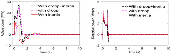
Figure 9.
The active and reactive power of BESS with the load event.
5.2. Generation Contingency Event
PV power output is subjected to intermittent and uncertainty, which require a sufficient level of contemplation to maintain system reliability and security. To evaluate further the efficacy of the proposed BESS control, the dynamic behaviour of the network was investigated following a temporary reduction of the largest PV farm output. A 85% reduction of PV farm output was applied for the duration of 0.2–3.2 s, and the comparative performance of the different BESS control modes was evaluated. Figure 10 demonstrates that without a BESS, the minimum frequency reached the lowest value of 49.307 Hz and thus exceeded the grid operating standards. On the contrary, the incorporated BESS effectively supplied additional damping to the system that regulated the frequency deviation of the generators within ±0.5 Hz. Nevertheless, IE- and PFC-regulated BESS manifested a slightly better frequency outcome, and this was clearly noticeable by taking a closer look at the lower minimum frequency and ROCOF value, as shown in Table 2. This was an expected result, as IE provided an immediate response to the frequency deviation before the droop controller came into action, and then, the droop controller took control linearly; therefore, the combination of IE and PFC contributed to providing better attenuation of the frequency derivative and minimum frequency nadir.
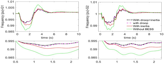
Figure 10.
The frequency (pu) oscillation of generators with the generation event.
Table 2.
The frequency results of G1 with the load event.
The voltage response at PCC shown in Figure 11 illustrated that the PCC voltage was not affected much during the generation event. Therefore, the reactive power contribution was relatively small, as illustrated in Figure 12. The BESS active power exhibited in Figure 12 showed that droop-controlled BESS provided the maximum active power (18.66 MW) at a certain time. However, the overall performance was not better than the combined IE- and PFC-regulated BESS control. The sum of total energy supplied by BESS in different operation modes revealed that a higher amount of energy was supplied by the assimilated IE- and PFC-regulated BESS, which also demonstrated better frequency dynamic behaviour.
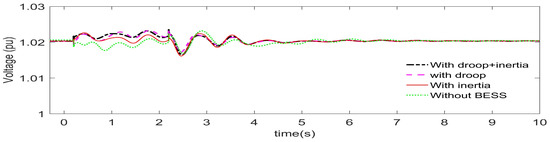
Figure 11.
The voltage (pu) at PCC with the generation event.
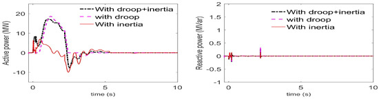
Figure 12.
The active and reactive power of BESS with the generation event.
5.3. BESS Recharging with FDSR
Battery SOC changes due to the exchange of BESS power with the grid and also the inherent self-discharging characteristics of the battery. Therefore, SOC recharging facility is required to ensure the battery is charged enough to participate in exchanging power whenever it is needed. A 15 Ah battery capacity and a charging current of 0.05 pu were used to demonstrate the proposed SOC recovery strategy (FDSR). In order to simulate the SOC recovery strategy, a permanent 20% load growth was applied at Load A at time t = 0 s. This would result in a reduction in grid frequency, and as the frequency dropped lower than the deadband limit, BESS action took place. BESS would inject power to the grid to improve grid frequency as long as it had sufficient SOC. Once battery SOC reaches the minimum SOC, battery needs to be charged. The comparative results of the conventional approach and the proposed SOC recovery strategy are demonstrated in Figure 13a–d.
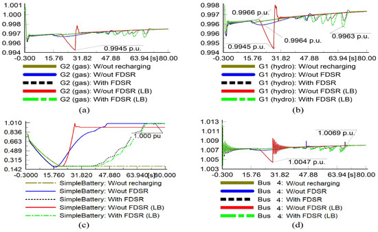
Figure 13.
Generator frequency (a,b) and battery SOC (c) and bus voltage (d) with the SOC recharging strategy. FDSR, frequency-dependent SOC recovery; LB, large BESS.
Figure 13c shows that at approximately t = 15 s, battery SOC reached the minimum SOC and the battery stopped injecting power to the grid according to the design constraints, as in (11). As the battery reached the minimum SOC, this resulted in a frequency reduction to 49.83 Hz before it finally recovered to the deadband boundary. With the conventional SOC recovery method (w/out FDSR), the battery started to recharge immediately as soon as the battery reached the minimum SOC. The battery would consume energy from the grid to be recharged, and this dragged down more the already lowered frequency to 49.82 Hz for the generators (G1, G2), as illustrated in Figure 13a,b. However, with the proposed FDSR, the battery did not participate in battery recharging, i.e., it consumed energy from the grid until the grid frequency reached the deadband boundaries ( ≥ 0.997 pu), i.e., within the nominal grid operation limit, which was at about t = 37.5 s. It can be seen that there were ups and downs in the frequency response during FDSR-based charging. This was due to the fact that when the frequency was equal to or greater than 0.997 pu, the battery attempted to charge and consumed energy from the grid; this caused the frequency to drop below 0.997 pu, and battery stopped charging immediately and waited until the frequency reached 0.997 pu. This continued until SOC reached the maximum SOC.
In order to further demonstrate the effectiveness of the proposed FDSR approach, a higher charging current and rated BESS power capacity were applied, which exemplified the high power capacity of BESS for SOC recovery. The large BESS (LB) converter (50 MW) with a battery capacity of 2.5 Ah and in response to the same load growth frequency response was slightly better, but at the expense of a faster reduction in battery SOC. With LB and a charging current of 0.5 pu and without FDSR (LB), the battery started consuming energy immediately (approximately at t = 20.4 s) for recharging. It can be seen that due to the consumption of higher energy from the grid, the grid frequency considerably reduced to a lower value (49.745 Hz). However, with the proposed FDSR (LB), BESS delayed its battery charging until the grid frequency satisfied the FDSR constraints and thus avoided impacting the grid frequency negatively during SOC recovery. In addition to grid frequency, PCC voltage was also affected by the uncontrolled battery charging (w/out FDSR (LB)). Without the proposed FDSR, the PCC voltage reduced to 1.0047 pu from its pre-charging voltage of 1.0075 pu, as depicted in Figure 13d. On the contrary, PCC voltage drop was limited to 1.0069 with FDSR (LB), which showed a significant improvement in the grid voltage. These observations clearly indicated that without the proposed FDSR, SOC recovery could hamper the performance of the controller and degrade grid performance instead of enhancing it. With larger BESS capacity, the consequences could be severe for the already seriously affected grid in terms of frequency and voltage. On the contrary, FDSR ensured that battery recharging took place when the grid frequency was stable and thus overcame the negative impact of the conventional SOC recovery strategy on both voltage and frequency.
5.4. Single-Phase-to-Ground Fault
In order to demonstrate the efficacy of the proposed BESS control design in fault conditions, a single-phase-to-ground fault event was carried out. The fault was applied at bus 4 for a duration of t = 0–150 ms. The performance of the generators, the bus voltage at bus 4, and BESS power output are illustrated in Figure 14, Figure 15 and Figure 16. The frequency of generators G1 and G2 as shown in Figure 14 indicated that the system experienced the highest rise and lowest drop in frequency without a BESS. However, it was observed that the comparative performance of various BESS control approaches was a mix of experience in terms of frequency rise and drop throughout the transient periods. The droop and combined control of BESS demonstrated a similar level of superior performance compared to the inertia-controlled BESS in terms of frequency rise and without a BESS condition. It is worth noting that for the studied contingency event, the frequency did not violate the mandatory grid limit of ±0.5 Hz for both the frequency and df/dt, as illustrated in Table 3.
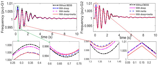
Figure 14.
The frequency (pu) oscillation of generators with a single-phase-to-ground fault.
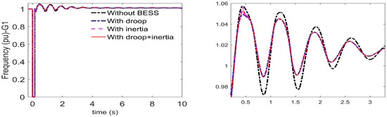
Figure 15.
The voltage (pu) oscillation of generators with a single-phase-to-ground fault.
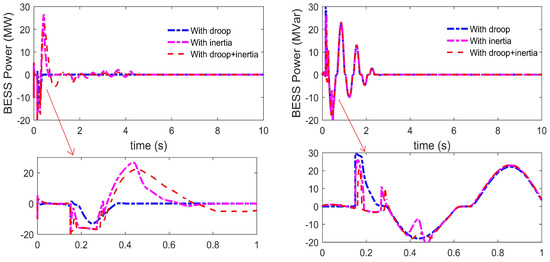
Figure 16.
The active and reactive power of BESS with a single-phase-to-ground fault.
Table 3.
The frequency results of G1 with a single-phase-to-ground fault.
On the contrary, the inertia and combined control manifested slightly better response in regards to the voltage drop between t = 0.6–0.75 s. In contrast, the droop and combined control exhibited a superior frequency drop response during t = 1.3–1.45 s, as shown in Figure 14. Furthermore, the proposed method established the superior performance for df/dt having the lowest value.
The voltage responses as shown in Figure 15 exhibited that BESS provided enhanced performance as compared to without a BESS in all control modes, and the voltage response was almost identical for all control designs throughout the transient periods. Nonetheless, droop-controlled BESS handled the frequency rise more effectively than the combined-controlled BESS. The amount of reactive power participation was substantial as the voltage oscillations were very high for this particular contingency event, as shown in Figure 16. BESS active power as shown in Figure 16 delineated that the inertia and combined control regulated the output more effectively than the droop control, which was reflected in the frequency of generators and df/dt, as shown in Figure 14 and Table 3, respectively.
6. Conclusions
In this paper, BESS was designed to provide voltage and frequency support and improve the stability of the grid. An enhanced consolidated IE- and PFC-regulated frequency controller and droop-regulated voltage controller were presented for supporting both the frequency and voltage stability with a high penetration of renewable sources. In addition, a novel frequency-dependent battery SOC recovery strategy was also suggested that allowed the battery to be recharged without imposing a negative impact on grid frequency. The battery was recharged when BESS was in idle mode and SOC was above the specified threshold or below the minimum SOC.
The simulation results of the comparative performances demonstrated that in comparison to individual IE or PFC service, the proposed amalgamated frequency controller performed the best in regulating the frequency response. The lower ROCOF and higher minimum frequency values were achieved with the proposed controller. As expected, IE with PFC service entailed a higher energy rating of BESS as this required BESS operation for longer periods. Furthermore, BESS exhibited a lower voltage drop than without a BESS during the contingency periods. Moreover, without FDSR, SOC recovery could have a severe impact on grid frequency and voltage as the battery consumed energy from the grid, which could be severe with high battery capacity and poor grid frequency. Nevertheless, the proposed FDSR demonstrated effective SOC recovery without negatively affecting either the grid frequency or voltage as FDSR delayed the battery recharging until the grid frequency was restored to the nominal operation limit.
Author Contributions
Conceptualization, methodology, software validation, formal analysis, and original draft preparation were done by U.D.; editing and supervision were carried out by A.K. and J.S. All authors read and agreed to the published version of the manuscript.
Funding
This work was supported by the Victoria University International Postgraduate Research Scholarship (IPRS) scheme.
Conflicts of Interest
The authors declare no conflict of interest.
Appendix A
Battery parameters: Initial SOC = 0.8 pu, battery cell capacity = 200 Ah, parallel cells = 65, nominal source voltage = 0.9 kV, internal resistance () = 0.001 pu. PI parameter: = 1.5, = 0.01, = 2, = 0.01, = 0.035. Current controller PI parameter: = = 1, = = 0.001.
Network parameters: PV Farm A = 69 MW, PV Farm B = 45 MW, Wind Farm A = Wind Farm B = 50 MW.
References
- Scenario Outlook & Adequacy Forecast 2014–2030; European Network of Transmission System 428 Operators for Electricity: Brussels, Belgium, 2014.
- D’Arco, S.; Suul, J.A.; Fosso, O.B. A Virtual Synchronous Machine implementation for distributed control of power converters in SmartGrids. Elect. Power Syst. Res. 2015, 122, 180–197. [Google Scholar] [CrossRef]
- Gu, W.; Liu, W.; Shen, C.; Wu, Z. Multi-stage underfrequency load shedding for islanded microgrid with equivalent inertia constant analysis. Int. J. Elect. Power Energy Syst. 2013, 46, 36–39. [Google Scholar] [CrossRef]
- Zhu, J.; Booth, C.D.; Adam, G.P.; Roscoe, A.J.; Bright, C.G. Inertia Emulation Control Strategy for VSC-HVDC Transmission Systems. IEEE Trans. Power Syst. 2013, 28, 1277–1287. [Google Scholar] [CrossRef]
- Engleitner, R.; Nied, A.; Cavalca, M.S.M.; da Costa, J.P. Dynamic Analysis of Small Wind Turbines Frequency Support Capability in a Low-Power Wind-Diesel Microgrid. IEEE Trans. Ind. Appl. 2018, 54, 102–111. [Google Scholar] [CrossRef]
- Nanou, S.I.; Papakonstantinou, A.G.; Papathanassiou, S.A. A generic model of two-stage grid-connected PV systems with primary frequency response and inertia emulation. Elec. Power Syst. Res. 2015, 127, 186–196. [Google Scholar] [CrossRef]
- Liu, H.; Qi, J.; Wang, J.; Li, P.; Li, C.; Wei, H. EV Dispatch Control for Supplementary Frequency Regulation Considering the Expectation of EV Owners. IEEE Trans. Smart Grid 2018, 9, 3763–3772. [Google Scholar] [CrossRef]
- Aliabadi, S.F.; Taher, S.A.; Shahidehpour, M. Smart Deregulated Grid Frequency Control in Presence of Renewable Energy Resources by EVs Charging Control. IEEE Trans. Smart Grid 2018, 9, 1073–1085. [Google Scholar] [CrossRef]
- Gonzalez-Longatt, F.M.; Alhejaj, S.M. Enabling inertial response in utility-scale battery energy storage system. In Proceedings of the 2016 IEEE Innovative Smart Grid Technologies - Asia (ISGT-Asia), Melbourne, Australia, 28 November–1 December 2016; pp. 605–610. [Google Scholar]
- Datta, U.; Kalam, A.; Shi, J. Battery energy storage system for transient frequency stability enhancement of a large-scale power system. In Proceedings of the Australasian Universities Power Engineering Conference, Melbourne, Australia, 19–22 November 2017; pp. 1–5. [Google Scholar]
- Shotorbani, A.M.; Mohammadi-Ivatloo, B.; Wang, L.; Ghassem-Zadeh, S.; Hosseini, S.H. Distributed secondary control of battery energy storage systems in a stand-alone microgrid. IET Gen. Trans. Dist. 2018, 12, 3944–3953. [Google Scholar] [CrossRef]
- Vazquez, N.; Yu, S.S.; Chau, T.K.; Fernando, T.; Iu, H.H. A Fully Decentralized Adaptive Droop Optimization Strategy for Power Loss Minimization in Microgrids with PV-BESS. IEEE Trans. Energy Conv. 2019, 34, 385–395. [Google Scholar] [CrossRef]
- Li, J.; Xiong, R.; Yang, Q.; Liang, F.; Zhang, M.; Yuan, W. Design/test of a hybrid energy storage system for primary frequency control using a dynamic droop method in an isolated microgrid power system. Appl. Energy 2017, 201, 257–269. [Google Scholar] [CrossRef]
- Kerdphol, T.; Rahman, F.S.; Mitani, Y.; Watanabe, M.; Küfeoǧlu, S. Robust Virtual Inertia Control of an Islanded Microgrid Considering High Penetration of Renewable Energy. IEEE Access 2018, 6, 625–636. [Google Scholar] [CrossRef]
- Fini, M.H.; Golshan, M.E.H. Determining optimal virtual inertia and frequency control parameters to preserve the frequency stability in islanded microgrids with high penetration of renewables. Elect. Power Syst. Res. 2018, 154, 13–22. [Google Scholar] [CrossRef]
- Yue, M.; Wang, X. Grid Inertial Response-Based Probabilistic Determination of Energy Storage System Capacity Under High Solar Penetration. IEEE Trans. Sust. Energy 2015, 6, 1039–1049. [Google Scholar] [CrossRef]
- Aghamohammadi, M.R.; Abdolahinia, H. A new approach for optimal sizing of battery energy storage system for primary frequency control of islanded Microgrid. Int. J. Elect. Power Energy Syst. 2014, 54, 325–333. [Google Scholar] [CrossRef]
- Toma, L.; Sanduleac, M.; Baltac, S.A.; Arrigo, F.; Mazza, A.; Bompard, E.; Musa, A.; Monti, A. On the virtual inertia provision by BESS in low inertia power systems. In Proceedings of the 2018 IEEE International Energy Conference (ENERGYCON), Limassol, Cyprus, 3–7 June 2018; pp. 1–6. [Google Scholar]
- Goya, T.; Omine, E.; Kinjyo, Y.; Senjyu, T.; Yona, A.; Urasaki, N.; Funabashi, T. Frequency control in isolated island by using parallel operated battery systems applying H-infinity control theory based on droop characteristics. IET Renew. Power Gen. 2011, 5, 160–166. [Google Scholar] [CrossRef]
- Li, H.; Wang, J.; Du, Z.; Zhao, F.; Liang, H.; Zhou, B. Frequency control framework of power system with high wind penetration considering demand response and energy storage. J. Eng. 2017, 2017, 1153–1158. [Google Scholar] [CrossRef]
- Wen, Y.; Li, W.; Huang, G.; Liu, X. Frequency Dynamics Constrained Unit Commitment with Battery Energy Storage. IEEE Trans. Power Syst. 2016, 31, 5115–5125. [Google Scholar] [CrossRef]
- Knap, V.; Chaudhary, S.K.; Stroe, D.; Swierczynski, M.; Craciun, B.; Teodorescu, R. Sizing of an Energy Storage System for Grid Inertial Response and Primary Frequency Reserve. IEEE Trans. Power Syst. 2016, 31, 3447–3456. [Google Scholar] [CrossRef]
- Brogan, P.V.; Best, R.J.; Morrow, D.J.; McKinley, K.; Kubik, M.L. Effect of BESS Response on Frequency and RoCoF During Underfrequency Transients. IEEE Trans. Power Sys. 2019, 34, 575–583. [Google Scholar] [CrossRef]
- Zeraati, M.; Hamedani Golshan, M.E.; Guerrero, J.M. Distributed Control of Battery Energy Storage Systems for Voltage Regulation in Distribution Networks with High PV Penetration. IEEE Trans. Smart Grid 2018, 9, 3582–3593. [Google Scholar] [CrossRef]
- Serban, I.; Marinescu, C. Control Strategy of Three-Phase Battery Energy Storage Systems for Frequency Support in Microgrids and with Uninterrupted Supply of Local Loads. IEEE Trans. Power Electron. 2014, 29, 5010–5020. [Google Scholar] [CrossRef]
- Alhejaj, S.M.; Gonzalez-Longatt, F.M. Investigation on grid-scale BESS providing inertial response support. In Proceedings of the 2016 IEEE International Conference on Power System Technology (POWERCON), Wollongong, Australia, 28 September–1 October 2016; pp. 1–6. [Google Scholar]
- Xu, Q.; Xiao, J.; Wang, P.; Pan, X.; Wen, C. A Decentralized Control Strategy for Autonomous Transient Power Sharing and State-of-Charge Recovery in Hybrid Energy Storage Systems. IEEE Trans. Sustain. Energy 2017, 8, 1443–1452. [Google Scholar] [CrossRef]
- Xiao, J.; Wang, P.; Setyawan, L. Hierarchical Control of Hybrid Energy Storage System in DC Microgrids. IEEE Trans. Ind. Electron. 2015, 62, 4915–4924. [Google Scholar] [CrossRef]
- Zhu, D.; Zhang, Y.A. Optimal Coordinated Control of Multiple Battery Energy Storage Systems for Primary Frequency Regulation. IEEE Trans. Power Syst. 2019, 34, 555–565. [Google Scholar] [CrossRef]
- Datta, U.; Kalam, A.; Shi, J. Battery Energy Storage System Control for Mitigating PV Penetration Impact on Primary Frequency Control and State-of-Charge Recovery. IEEE Trans. Sustain. Energy 2019, 11, 746–757. [Google Scholar] [CrossRef]
- ENTSO. P1—Policy 1: Load-Frequency Control and Performance. Available online: http://kom.aau.dk/project/smartcool/restricted_files/2012.11.06-AAU/ENTSOE_UCTE_frequency_reserves.pdf (accessed on 1 October 2018).
- Kundur, P.; Balu, N.J. Power System Stability And Control; McGraw-Hill: New York, NY, USA, 1994. [Google Scholar]
- Australian Energy Market Operator. Integrating Renewable Energy—Wind Integration Studies Report. Available online: http://www.aemo.com.au/-/media/Files/PDF/Integrating-Renewable-Energy--Wind-Integration-Studies-Report-2013pdf.pdf (accessed on 2 October 2018).
- Operator, A.E.M. International Review of Frequency Control. Available online: https://www.aemo.com.au/-/media/Files/Electricity/NEM/Security_and_Reliability/Reports/2016/FPSS---International-Review-of-Frequency-Control.pdf (accessed on 31 March 2020).
- AEMC. The Frequency Operating Standard Stage One Final-for-Publi. Available online: https://www.aemc.gov.au/sites/default/files/content/ce48ba94-b3a9-4991-9ef9-e05814a78526/REL0065-Review-of-the-Frequency-Operating-Standard-Final-for-publi.pdf (accessed on 15 September 2018).
- Duckwitz, D.; Fischer, B. Modeling and Design of df/dt -Based Inertia Control for Power Converters. IEEE J. Emerg. Sel. Top. Power Electron. 2017, 5, 1553–1564. [Google Scholar] [CrossRef]
- Datta, U.; Kalam, A.; Shi, J. Battery Energy Storage System to Stabilize Transient Voltage and Frequency and Enhance Power Export Capability. IEEE Trans. Power Syst. 2019, 34, 1845–1857. [Google Scholar] [CrossRef]
- Shen, P.; Ouyang, M.; Lu, L.; Li, J.; Feng, X. The Co-estimation of State of Charge, State of Health, and State of Function for Lithium-Ion Batteries in Electric Vehicles. IEEE Trans. Veh. Tech. 2018, 67, 92–103. [Google Scholar] [CrossRef]
- Mukherjee, N.; De, D. A New State-of-Charge Control Derivation Method for Hybrid Battery Type Integration. IEEE Trans. Energy Conv. 2017, 32, 866–875. [Google Scholar] [CrossRef]
- Zhang, R.; Hredzak, B.; Morstyn, T. Distributed Control with Virtual Capacitance for the Voltage Restorations, State of Charge Balancing and Load Allocations of Heterogeneous Energy Storages in a DC Datacenter Microgrid. IEEE Trans. Energy Conv. 2018, 34, 1296–1308. [Google Scholar] [CrossRef]
- Hu, X.; Yuan, H.; Zou, C.; Li, Z.; Zhang, L. Co-Estimation of State of Charge and State of Health for Lithium-Ion Batteries Based on Fractional-Order Calculus. IEEE Trans. Veh. Tech. 2018, 67, 10319–10329. [Google Scholar] [CrossRef]


© 2020 by the authors. Licensee MDPI, Basel, Switzerland. This article is an open access article distributed under the terms and conditions of the Creative Commons Attribution (CC BY) license (http://creativecommons.org/licenses/by/4.0/).