Article

Numerical Study of Heat Transfer in Gravity-Driven Particle Flow around Tubes with Different Shapes †

1
Key Laboratory of Thermo-Fluid Science and Engineering, Ministry of Education, Xi’an Jiaotong University, Xi’an 710049, China
2
Department of Energy Sciences, Lund University, 22100 Lund, Sweden
*
Authors to whom correspondence should be addressed.
This paper is an extended version of our paper published in the 22nd International Conference on Process Integration, Modelling, Optimization for Energy Saving and Pollution Reduction (PRES’ 19), Aghios Nikolaos, Crete, Greece, 20–23 October 2019; pp. 235–240.
Energies 2020, 13(8), 1961; https://doi.org/10.3390/en13081961
Submission received: 27 February 2020 / Revised: 14 April 2020 / Accepted: 14 April 2020 / Published: 16 April 2020

Abstract

:
In the present paper, the heat transfer of gravity-driven dense particle flow around five different shapes of tubes is numerically studied using discrete element method (DEM). The velocity vector, particle contact number, particle contact time and heat transfer coefficient of particle flow at different particle zones around the tube are carefully analyzed. The results show that the effect of tube shape on the particle flow at both upstream and downstream regions of different tubes are remarkable. A particle stagnation zone and particle cavity zone are formed at the upstream and downstream regions of all the tubes. Both the stagnation and cavity zones for the circular tube are the largest, and they are the smallest for the elliptical tube. As the particle outlet velocity (vout) changes from 0.5 mm/s to 8 mm/s at dp = 1.72 mm/s, when compared with the circular tube, the heat transfer coefficient of particle flow for the elliptical tube and flat elliptical tube can increase by 20.3% and 15.0% on average, respectively. The proper design of the downstream shape of the tube can improve the overall heat transfer performance more efficiently. The heat transfer coefficient will increase as particle diameter decreases.

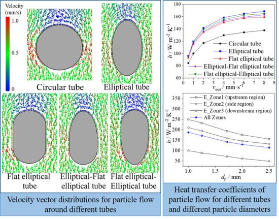
Graphical Abstract

1. Introduction

In the recent years, the world’s energy and environmental problems have become more and more prominent, which makes it urgent to improve energy efficiency and develop sustainable energy techniques. Moving bed heat exchanger (MBHE), with the advantages of low cost, clean energy and wide particle size adaptation, is gradually applied in many high temperature waste heat recovery industries [1], such as slag [2], cement [3], coke [4] and concentrated solar power (CSP) [5]. For the MBHE, the granular flow inside is driven by the gravity, and the heat transfer is relatively lower [6] as compared with packed bed [7] or fluidized bed [8]. Therefore, it is important to improve the heat transfer of particle flow in the MBHE.
The type of heat transfer element in the MBHE may include horizontal tubes, vertical tubes and parallel plates. For the MBHE with vertical tubes [9] or parallel plates inside [10], the solid particles move vertically along the tubes or palates without fully mixing, which would limit the heat transfer of particle flow along the tubes or plates in the MBHE. However, the particle flow around a horizontal tube should be disordered and fully mixed [11], and the heat transfer around the horizontal tube should be better. Many researchers have studied the effects of particle material, particle size, particle velocity, finned tube and layout of horizontal tubes in the MBHE. Qoaider et al. [12] found that the heat transfer performance of MBHE with mixed particles of 50% sand and 50% basalt particles were 30% better than that of MBHE with 100% sand particles by experiment. Increasing particle velocity can significantly improve the heat transfer coefficient, Al-Ansary et al. [13] found that the heat transfer coefficient would increase from 80 W/(m2·K) to 160 W/(m2·K) as the sand velocity increased from 1 mm/s to 3 mm/s. Nguyen et al. [14] found that, when the particle velocity changes from 3 mm/s to 10 mm/s, finned tubes can enhance heat transfer as compared with the smooth tubes. Liu et al. [1] analyzed the effects of particle diameter, particle velocity and tube arrangement on the performances of heat exchanger by experiment. They found that the heat transfer performance is better in staggered heat exchanger and the heat transfer coefficient increased as the particle size decreased or as the particle velocity increased. However, when the particles flowed around the horizontal tube, a stagnation zone would form at the upstream region of the tube and a cavity zone would form at the downstream region of the tube [15], which would seriously affect the flow and heat transfer of particles [16]. The particles in the stagnation zone move slowly or even remain stationary, while the particles in the cavity zone are almost untouched with the tube wall. Bartsch and Zunft studied the dense granular flow around horizontal tubes by CFD model [17], discrete element method (DEM) model and experiment [18]. The simulation results could well capture both the stagnation zone and cavity zone at the upstream and downstream of the tube, which was consistent with the experimental results. The heat transfer coefficient in these two zones was the lowest, and the heat transfer mainly occurred on the side region of the tube wall [19]. Therefore, it is an effective way to improve heat transfer performance of particle flow in the MBHE by reducing both the stagnation zone and cavity zone around the tube, such as using vibration or profiled tubes. Guo et al. [20] found that vibration could accelerate the renewal of particles at the upstream region of the tube, strengthen particle contact at the downstream region of the tube and increase the heat transfer coefficient of particle flow around the tube. However, the vibration may also significantly increase the wear rate of the tube. As for profiled tubes, Morris et al. [21] developed a continuum model for flowing particles heat transfer and studied the particle flow in the hexagonal tube array in the solar receiver [22], where the particle inlet velocity was up to 1 m/s and the thermal performance was obviously affected by the particle size. They found that the overall heat transfer increased as particle mass flow rate increased. Furthermore, Takeuchi [11] experimentally studied the heat transfer of particle flow around a circular tube, an elliptical tube and a lenticular tube. The study showed that the effect of tube shape on the heat transfer performance of particle flow around the tube was remarkable, and the performance of lenticular tube was the best.
According to the above studies, it should be noted that the effect of tube shape on the heat transfer of particle flow around tube is remarkable. In order to further understand the mechanism of this effect and improve the heat transfer performance of particle flow in the MBHE, the heat transfer of gravity-driven dense particle flow around different tubes was numerically investigated in the present study, including circular tube, elliptical tube, flat elliptical tube and the combination of elliptical tube and flat elliptical tube. A variety of factors, such as velocity vector, particle contact number, particle contact time and heat transfer coefficient of particle flow at different particle zones around the tube are carefully analyzed. Meanwhile, the effect of particle diameter on heat transfer is discussed. The results of the present study would be important and beneficial for the optimal design of MBHEs.

2. Physical Model and Computational Method

2.1. Physical Model

The physical model for particle flow around a single tube is presented in Figure 1. As shown in Figure 1a, the spherical particles flow around a single tube from the top to bottom in the particle flow channel and exchange heat with the tube wall. The dimensions of the particle flow channel are L (length) × W (width) × H (height), and the particle diameter (dp) is mainly fixed at 1.72 mm. The tube is located in the channel center. All the vertical channel walls are adiabatic, and the temperature of tube wall is kept at Ttube = 287 K. Particles are generated at the entrance of the flow channel, and the particle inlet temperature is kept at Tin = 773 K. All particles are driven by the gravity and have a dense filling in the flow channel. The particle velocity in the channel is controlled at the outlet [5], and the particle outlet velocity is kept constant along the vertical direction (z). As shown in Figure 1b, five different tubes are adopted for the study, including circular tube, elliptical tube, flat elliptical tube, elliptical-flat elliptical tube and flat elliptical-elliptical tube, where the perimeters of different tube cross sections are kept the same. Typical geometric parameters of the particle flow channel and tubes are presented in Table 1. In the present study, the particle flow around tube wall is divided into three zones, including the upstream region of the tube (Zone 1), the side region of the tube (Zone 2), and the downstream region of the tube (Zone 3). The geometric divisions of different particle zones are also presented in Figure 1b.

2.2. DEM Method and Heat Transfer Model

In the present study, the flow and heat transfer of particles are simulated with discrete element method (DEM). For DEM simulations, the Newton’s second law [23] is used to calculate the forces on each particle and track the particle motions. For gravity-driven dense particle flow, since the particle filling rate is high and particles move very slowly, the effect of the gas flow between particles is insignificant [24]. Therefore, the gas flow is not considered for the simulations, and the Hertz-Mindlin soft sphere model [25,26] is adopted to simulate the dense particle flow process, where the normal force and tangential force between particles are treated with equivalent spring, damper and slider to simplify the contact between particles. The contact force is calculated according to the normal overlap and tangential displacement of particles. The equations used to calculate the contact force of particle-particle or particle-wall are as follows:
F n = 4 3 E eq r eq δ n 3 / 2 + 2 5 6 ln e ln 2 e + π 2 2 E eq m eq r eq δ n V n rel
F t = { 8 G eq δ t r eq δ n + 2 5 6 ln e ln 2 e + π 2 8 G eq m eq r eq δ n V t rel | F t | < μ s | F n | μ s F n sign ( δ t ) | F t | μ s | F n |
where Fn and Ft are the normal and tangential components of the contact force. Eeq, Req, and meq are the equivalent Young’s modulus, radius, and mass. δn and δt are normal and tangential displacements. Vnrel and Vtrel are the relative normal and tangential translational velocities. e and μs are the restitution coefficient and the translational friction coefficient.
As for heat transfer of particle flow, the heat transfer form particle to particle (p-p) or from particle to the tube wall (p-w) includes heat conduction, thermal convection and thermal radiation, where the heat conduction consists of heat conduction inside particles, physical contact heat conduction and heat conduction through gas film surround particles. In the present study, since particles move quite slowly, the gas convection heat transfer is very small [27]. The thermal convection of gas flow between particles is not considered in the simulations. The heat transfer model adopted in the present paper is based on the following assumptions, (1) the diameter of all particles is the same; (2) the gas heat capacity is ignored [28]; (3) particles are wrapped with gas film and its thickness is 0.1 dp [29]; (4) the heat transfer between particles is along the radial direction of particles; (5) the thermal properties of gas and particles are kept constant, as listed in Table 2. The correlation of the heat transfer (Q) with temperature difference (ΔT), total thermal resistance (Rtotal) and time (t) is presented in Equation (3), and the total thermal resistance (Rtotal) is calculated based on the thermal resistance network, as shown in Figure 2.
Q = Δ t Δ T / R total
The thermal conduction resistance includes thermal conduction resistance inside particles (R1), physical contact thermal conduction resistance (R2) and thermal conduction resistance through gas film (R3). According to Fourier’s law [30], the thermal resistance R1 and the thermal resistance R3 are formulated as follows:
R 1 = 2 3 1 2 π k s r ( 1 cos α )
R 3 = [ β α 2 π k g r 2 sin θ cos θ l ij r sin θ r 2 ( r sin θ ) 2 d θ ] 1  
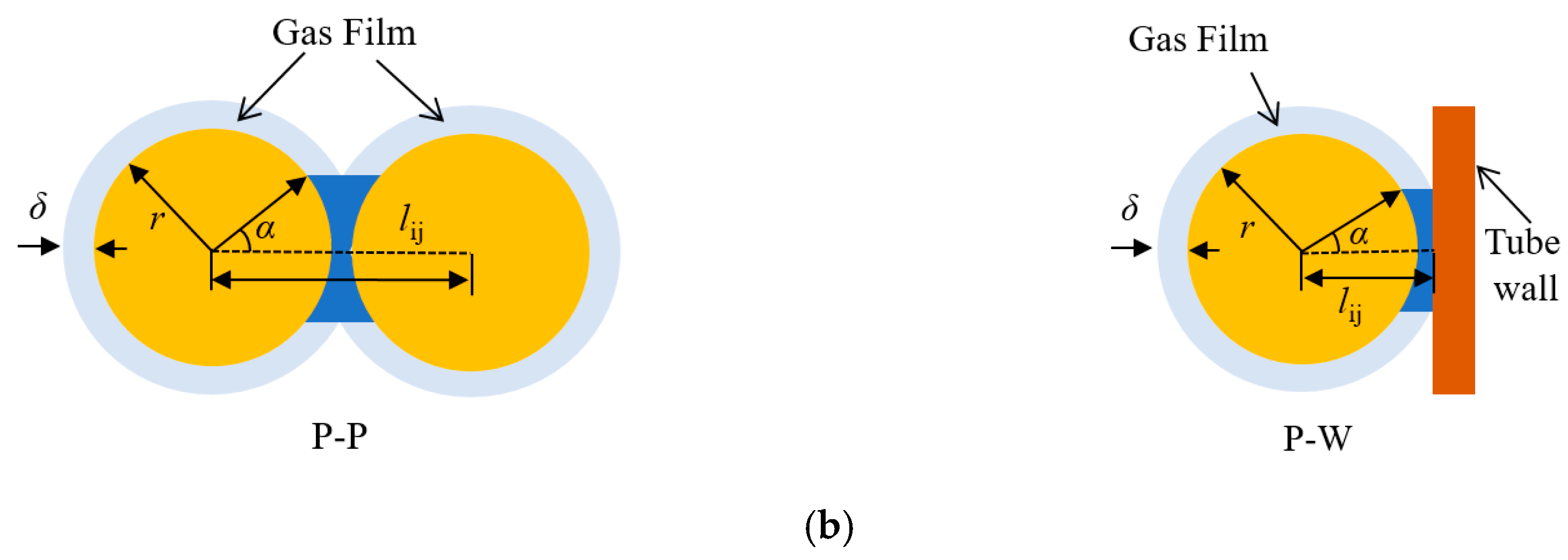
where α is an angle related to the intersection of gas film and β is a starting point angle for the calculation of thermal conduction resistance through gas film, which are both presented in Figure 3 and Equations (6) and (7); lij is the distance for the case of particle-particle or particle-wall, as shown in Figure 3; r is the particle radius and rg is the particle radius plus gas film (rg = 0.6 dp).
α = { arcsin ( r g 2 ( l ij 2 ) 2 / r ) ( p - p ) arcsin ( r g 2 l ij 2 / r ) ( p - w )  
β = arcos ( l ij 6.8 × 10 8 2 r )
when the contact is only with gas film and the gas film overlap is larger than gas free path, the value of β is equal to 0.
The physical contact thermal conduction resistance R2 [31] is formulated as follows:
R 2 = [ 2 k s ( 3 F n r 4 E eq ) 1 / 3 ] 1
where Fn is normal direction force and Eeq is Young’s modulus.
According to the Stefan–Boltzmann law, the thermal radiation resistance (R4) is presented in Equation (9). Xij is the view factor, as presented in Equation (10). σ is the Stefan–Boltzmann constant and ε is the surface emissivity. When the particle contacts with the tube wall, Xij is equal to 0.315 [32].
R 4 = [ σ ( T i 2 + T j 2 ) ( T i + T j ) ( 1 ε ε A ) i + 1 A i X ij + ( 1 ε ε A ) j ] 1
X ij = { [ 1 1 ( r i l ij ) 2 ] [ 1 1 ( r j l ij ) 2 ] ( l ij r i ) 2 ( p - p ) 0.315 ( p - w )
At the beginning of DEM simulations, randomly packed high-temperature particles were generated in the particle flow channel. Then, particles start to flow in the channel under gravity. High temperature particles are cooled when they flow around the tube. Meanwhile, new particles were generated and continuously enter into the channel at the inlet. During the whole simulation process, the total particle number inside the channel is kept constant. Typical mechanical parameters for the DEM simulations are listed in Table 3, and the heat transfer coefficient (h) of particle flow around the tube is defined as follows:
h = q A tube ( T in T tube )
where q is the heat flux on the tube wall; Atube is the heat transfer area of tube wall; Tin is the particle inlet temperature; Ttube is the tube wall temperature.
The variations of heat flux (q) on the tube wall with time for the particle flow around a circular tube at vout = 0.5 mm/s are presented in Figure 4. It shows that, when dq/dt is quite small (dq/dt < 0.05%), the particle flow and heat transfer around the tube should be quasi-steady. In the present study, the simulation results within the 30 s after the quasi-steady state are extracted for the analysis.

2.3. Model Validations

In order to validate the reliability and accuracy of present computational model and methods, the heat transfer coefficients obtained with DEM simulations are compared with the experimental results of Liu et al. [1]. The variations of heat transfer coefficient (h) for the particle flow through a tube row are presented in Figure 5. It is found that the variation trend of the heat transfer coefficients obtained by the DEM simulation is similar to the experimental results. The maximum deviation between the simulation and experimental results is 16.3%, and the average deviation is 11.8%. In the present simulation, the particle is simplified as sphere and the particle outlet velocity is kept constant for each certain case, while the particles used in the experiments [1] were irregular and the distribution of particle outlet velocity were not uniform. Therefore, the deviations exist between present simulation results and experimental results [1].

3. Results and Discussion

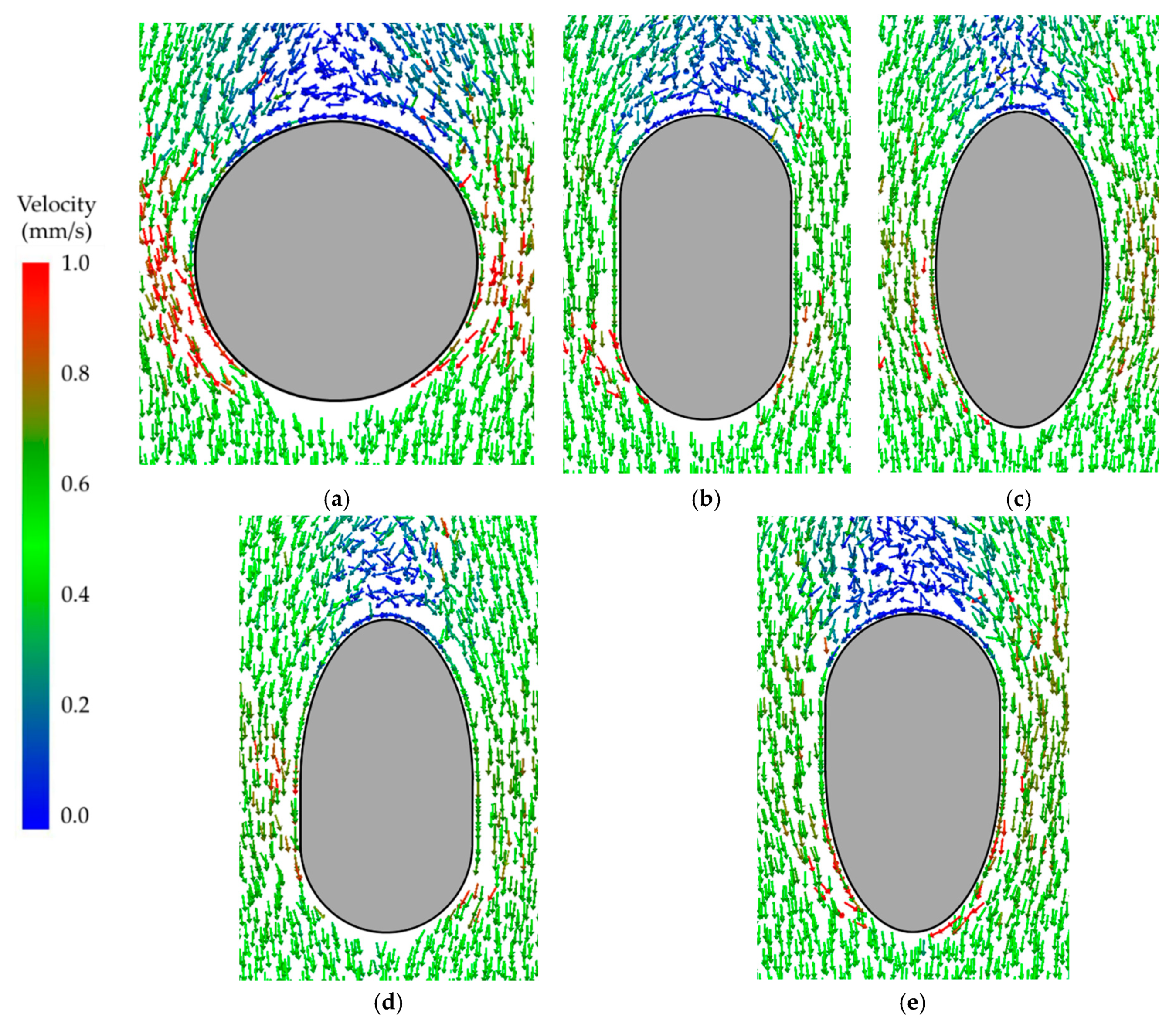
The velocity vector distributions of particle flowing around different tubes at a certain time are presented in Figure 6. This shows that the effect of tube shape on the particle flow at both upstream (Zone 1) and downstream (Zone 3) regions of different tubes is remarkable. It is noted that the particle velocity at the upstream region (Zone 1) of different tubes is very small and a particle stagnation zone is formed. Meanwhile, it is noted that, at the downstream region (Zone 3) of different tubes, a particle cavity zone is formed, where particles are almost untouched on the tube wall. For particle flow around different tubes, it is found that both the stagnation and cavity zones for the circular tube are the largest, and they are the smallest for the elliptical tube. This may indicate that, for the elliptical tube, particles can renew faster at the upstream region (Zone 1) of the tube and the tube wall can be touched with more particles at the downstream region (Zone 3) of the tube. Therefore, the heat transfer of particle flow around an elliptical tube would be better. For the elliptical-flat elliptical tube and flat elliptical-elliptical tube, the characteristics of the stagnation zone and cavity zone are consistent with the tube with the same shapes at upstream region and downstream region.
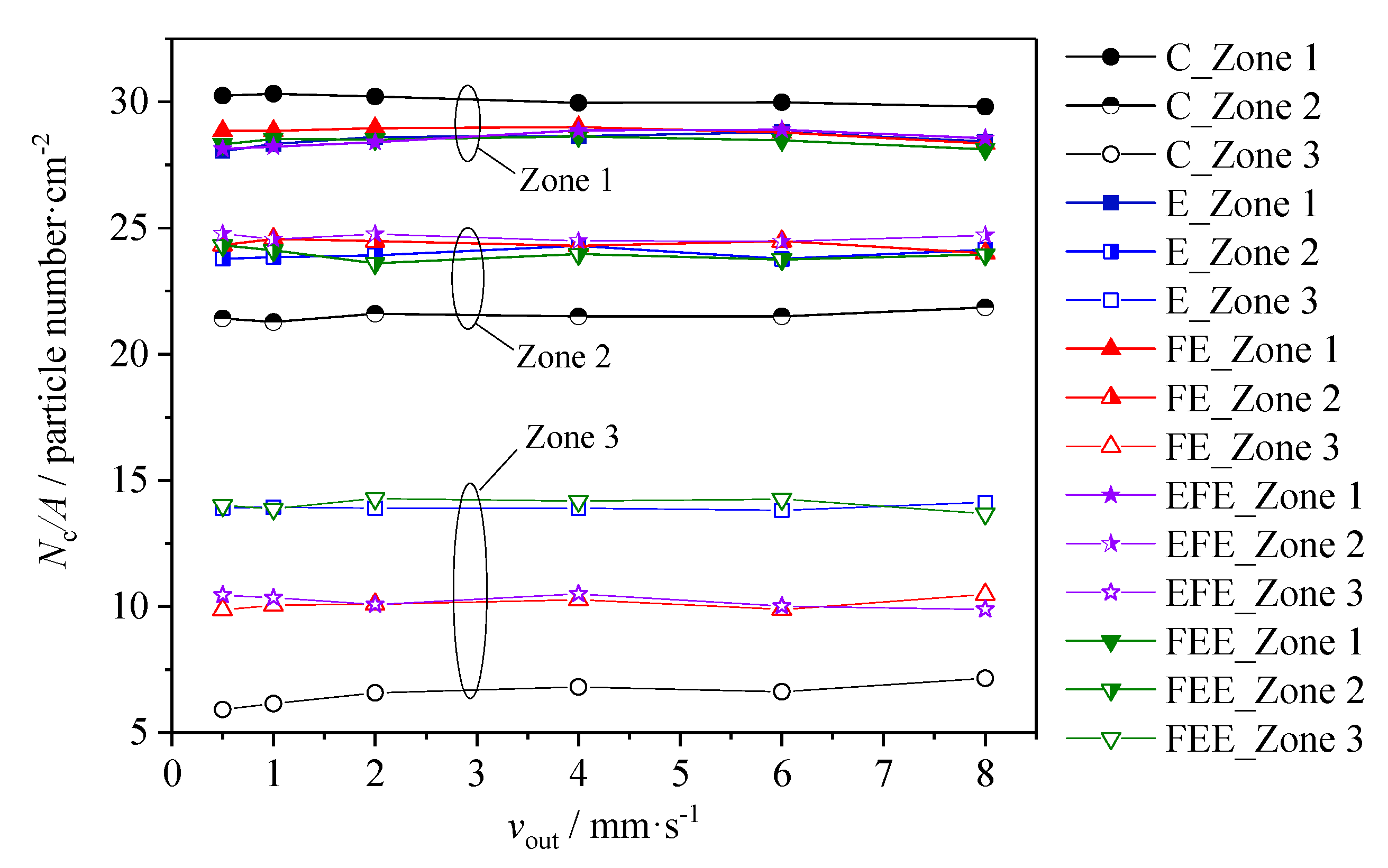
The variations of time-averaged particle contact number with vout for different tubes are presented in Figure 7. The contacting situation between particles and tube wall is well reflected by using time-averaged particle contacting number on the unit area of tube surface. In the present study, the tube wall is considered to be touched by particles as the gas film surrounding the particle surface (δ = 0.1 dp) touches the tube wall. As shown in Figure 7, when the particle outlet velocity (vout) varies from 0.5 mm/s to 8 mm/s, the particle contact numbers at different zones of all the tubes change very little with vout. The particle contact numbers at Zone 1 of all the tubes are the highest and they are the lowest at Zone 3. At Zone 1 and Zone 2, the particle contact numbers of elliptical tube, flat elliptical tube, elliptical-flat elliptical tube and flat elliptical-elliptical tube are close to each other. At Zone 1, the particle contact number of circular tube is a little higher than that of the elliptical tube, flat elliptical tube, elliptical-flat elliptical tube and flat elliptical-elliptical tube, while at Zone 2, the particle contact number of circular tube is a little lower. As for Zone 3, big differences of particle contact number existed for different tubes. As compared with the circular tube, the particle contact number at Zone 3 of the elliptical tube and flat elliptical tube can increase by 112.3% and 53.5%. Due to the same tube shape at the downstream region, the particle contact numbers at Zone 3 of the elliptical-flat elliptical tube and the flat elliptical-elliptical tube are quite close to those of the flat elliptical tube and elliptical tube.
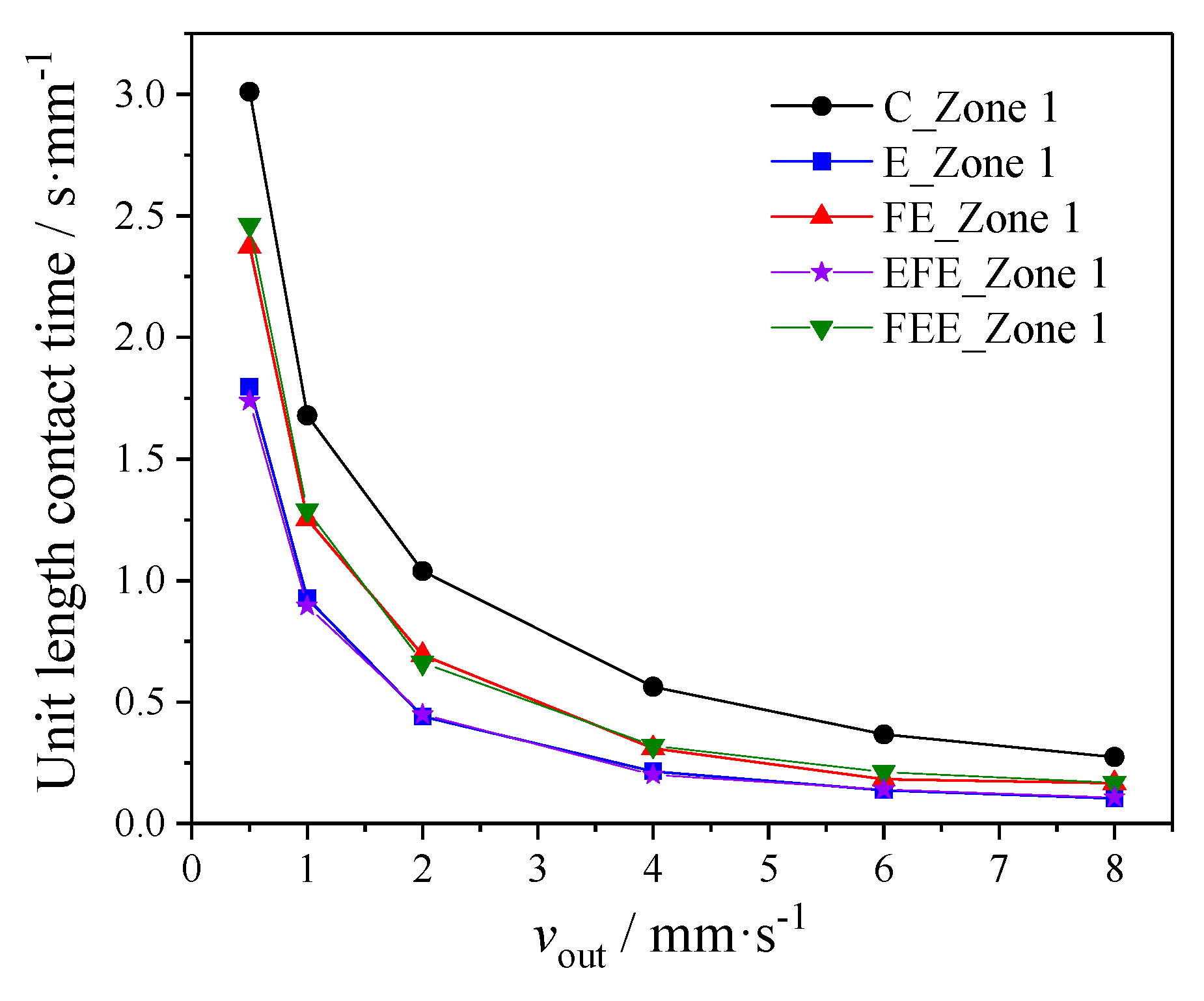
In order to compare the particle renewal situations at the stagnation zone (Zone 1) of particle flow around different tubes, the variations of particle contact time with vout at Zone 1 of different tubes are analyzed, as presented in Figure 8. The contacting time of particles with tube wall for unit length of tube is a cumulative variable. The contacting time of particles is accumulated when the tube wall is touched by the gas film surrounding the particle, which is the average result for particles contacting the tube at each time step. As shown in Figure 8, it is found that, as particle outlet velocity (vout) increases from 0.5 mm/s to 8 mm/s, the particle contact time with the tube wall at Zone 1 of different tubes decreases rapidly, and the particle flow at the stagnation zone of all the tubes is accelerated. Furthermore, it is found that under the same particle outlet velocity (vout), the particle contact time at Zone 1 of the circular tube is highest and it is the lowest for the elliptical tube, which means the particle flow renewal situation at the stagnation zone (Zone 1) of elliptical tube is the best. Due to the same tube shape at Zone 1, the particle contact times at Zone 1 of the elliptical-flat elliptical tube and the flat elliptical-elliptical tube are almost the same to those of the elliptical tube and flat elliptical tube. As compared with the circular tube, when vout = 0.5 mm/s, the particle contact time at Zone 1 of the elliptical tube and flat elliptical tube can decrease by 39% and 21%.
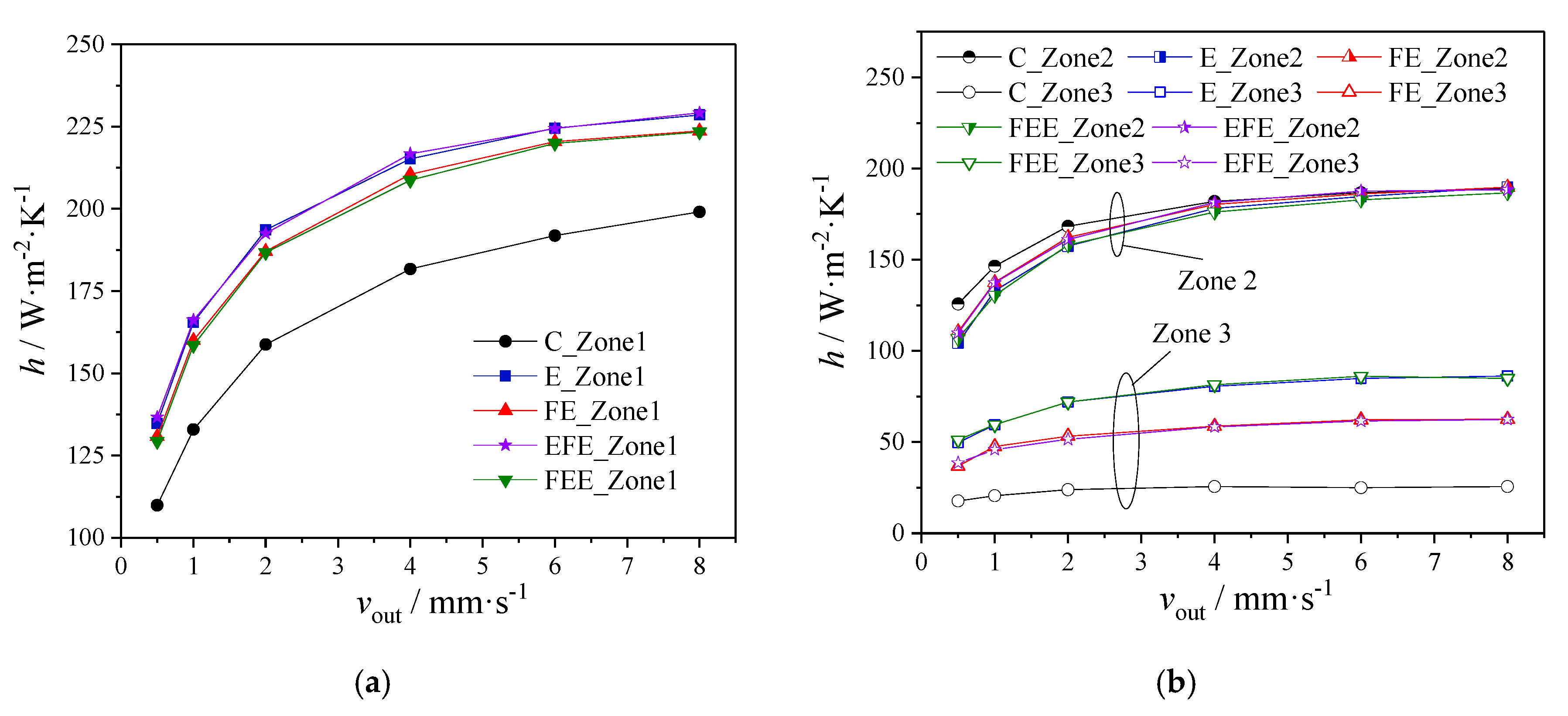
The variations of local heat transfer coefficients of particle flow with vout for different tubes are presented in Figure 9. The local heat transfer coefficient of particle flow at Zone 1 of elliptical tube is a little higher than that of the flat elliptical tube, while the local heat transfer coefficient of circular tube is the lowest, as shown in Figure 9a. At Zone 1, the difference of particle contact number between different tubes is small (see Figure 7), while the particle contact time of the circular tube is obviously higher (see Figure 8); therefore, the local heat transfer of particle flow at Zone 1 on the circular tube is lower. When the particle outlet velocity (vout) changes from 0.5 mm/s to 8 mm/s, as compared with the circular tube, the local heat transfer coefficient of particle flow at Zone 1 on the elliptical tube and flat elliptical tube can increase by 19.7% and 16.9% on average, respectively. As Zone 2 is concerned, it shows that the local heat transfer coefficients of particle flow on different tubes are quite similar, which may indicate that the particle contact situation at the side region of particle flow on different tubes should be similar, as shown in Figure 9b For the circular tube, although the particle contact number at Zone 2 is the lowest when compared with other tubes, there are more new particles contacting with the tube wall at Zone 2 due to the highest contact time at Zone 1, which would lead to similar heat transfer coefficients to those of other tubes. At Zone 3, it shows that the difference of local heat transfer coefficients of particle flow for different tubes is relatively large, as shown in Figure 9b. The local heat transfer coefficient of particle flow at Zone 3 for the elliptical tube is the highest and it is the lowest for the circular tube. The cavity zone formed at downstream region of the elliptical tube is the smallest (see Figure 6) and particle contact number at Zone 3 for the elliptical tube is the highest (see Figure 7); therefore, the local heat transfer of particle flow at Zone 3 for the elliptical tube is the highest. When the particle outlet velocity (vout) changes from 0.5 mm/s to 8 mm/s, as compared with the circular tube, the local heat transfer coefficient of particle flow at Zone 3 for the elliptical tube and flat elliptical tube can increase by 210.0% and 130.4% on average, respectively. Finally, it is found that the local heat transfer coefficients of the elliptical-flat elliptical tube and the flat elliptical-elliptical tube at Zone 1 and Zone 3 are almost the same to those of the tubes with the same shape at these zones.
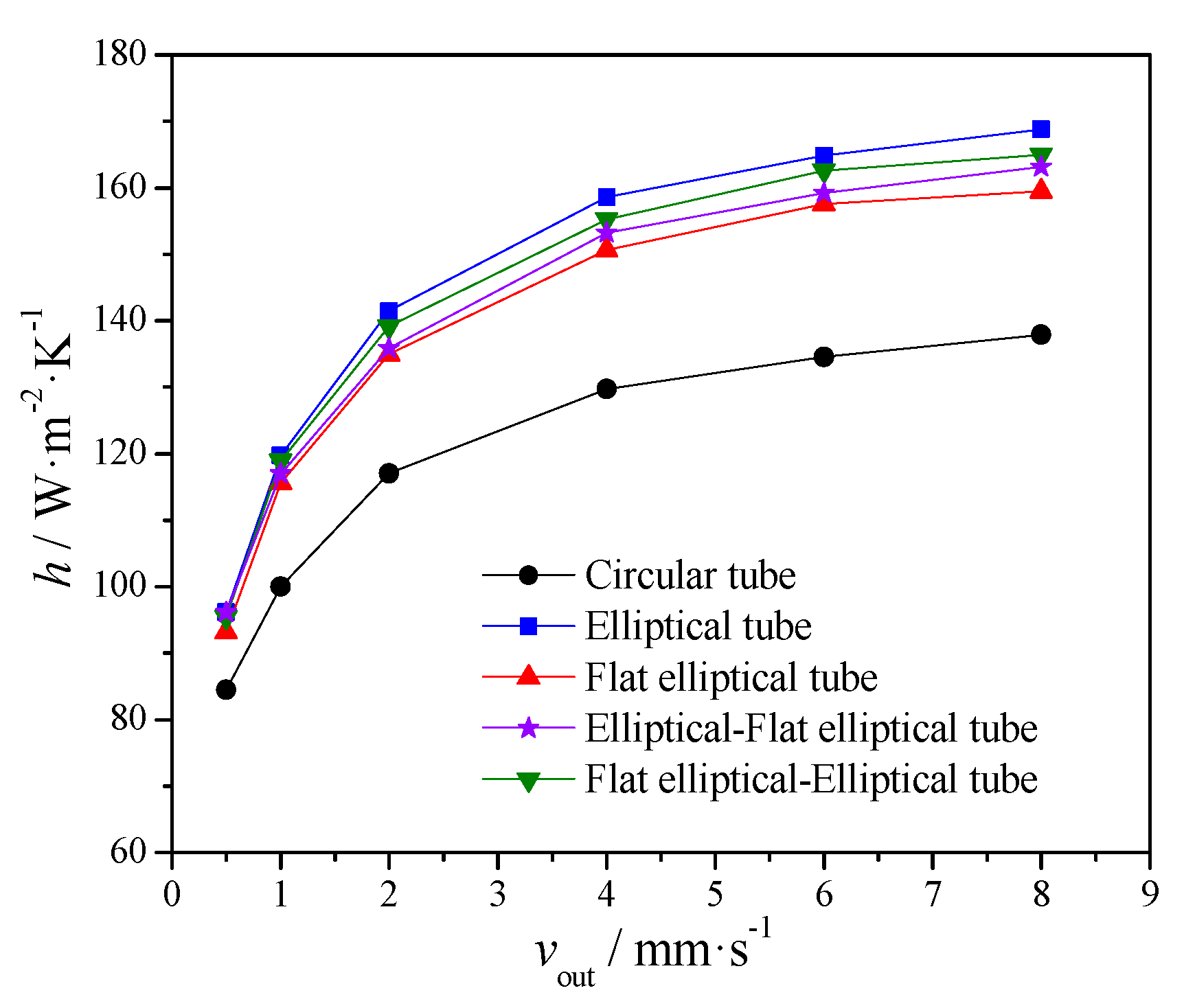
The variations of heat transfer coefficients of particles flow with vout for different tubes are presented in Figure 10. It shows that as the particle outlet velocity (vout) increases, the heat transfer coefficient of particle for all the tubes increases gradually. The heat transfer coefficient of particle flow around elliptical tube is the highest and it is the lowest for the circular tube. As the particle outlet velocity (vout) changes from 0.5 mm/s to 8 mm/s, when compared with the circular tube, the heat transfer coefficient of particle flow for the elliptical tube and flat elliptical tube can increase by 20.3% and 15.0% on average. As compared with the flat elliptical tube, the elliptical-flat elliptical tube would enhance the heat transfer at the upstream region of the tube, and the flat elliptical-elliptical tube would improve the heat transfer at the downstream region of the tube, as shown in Figure 9. The heat transfer coefficient of the flat elliptical-elliptical tube is higher than that of the elliptical-flat elliptical tube, which shows that the optimization of particle flow and heat transfer at the downstream region of the tube can improve the overall heat transfer performance more efficiently. The heat transfer coefficients of these two shapes of tubes are higher than that of the flat elliptical tube but lower than that of the elliptical tube.
Finally, the variations of heat transfer coefficients for the particle flow around an elliptical tube with different particle diameter (dp) are presented in Figure 11. It shows that, as the particle diameter decreases from 2.5 mm to 1 mm, the heat transfer coefficients of particle flow around the elliptical tube increase, which is consistent with the experimental results of Liu et al. [1]. When vout = 2 mm/s, as the particle diameter decreases from 2.5 mm to 1 mm, the local heat transfer coefficients of particle flow at the upstream region (E_Zone 1), side region (E_Zone 2) and downstream region (E_Zone 3) of an elliptical tube can increase by 61.1%, 59.4% and 102.6%, and the heat transfer coefficient around the elliptical tube can increase by 63.6% on average.

4. Conclusions

In the present study, the heat transfer of gravity-driven dense particle flow around different tubes was numerically investigated with discrete element method (DEM), including circular tube, elliptical tube, flat elliptical tube and the combination of elliptical tube and flat elliptical tube. A variety of factors, such as velocity vector, particle contact number, particle contact time and heat transfer coefficient of particle flow at different particle zones around the tube are carefully analyzed. Meanwhile, the effect of particle diameter on heat transfer is discussed. The main findings are as follows:
(1) The effect of tube shape on the particle flow at both upstream (Zone 1) and downstream (Zone 3) regions of different tubes is remarkable. A particle stagnation zone and particle cavity zone are formed at the upstream and downstream regions of all the tubes. Both the stagnation and cavity zones for the circular tube are the largest, and they are the smallest for the elliptical tube. Furthermore, the effect of tube shape on the particle contact number and particle contact time at different zones of particle flow for different tubes is quite different. As for the particle contact number, big differences existed at Zone 3 for different tubes. As compared with the circular tube, when dp = 1.72 mm, the particle contact number at Zone 3 of the elliptical tube and flat elliptical tube can increase by 112.3% and 53.5%, respectively. When vout = 0.5 mm/s and dp = 1.72 mm, the particle contact time at Zone 1 of the elliptical tube and flat elliptical tube can decrease by 39% and 21% as compared with the circular tube.
(2) The heat transfer performances of particle flow around different tubes are different. It is found that, at Zone 3, the difference of local heat transfer coefficients of particle flow for different tubes is quite large. When the particle outlet velocity (vout) changes from 0.5 mm/s to 8 mm/s at dp = 1.72 mm, as compared with the circular tube, the local heat transfer coefficient of particle flow at Zone 3 for the elliptical tube and flat elliptical tube can increase by 210.0% and 130.4% on average, respectively. Furthermore, as the particle outlet velocity (vout) changes from 0.5 mm/s to 8 mm/s at dp = 1.72 mm, when compared with the circular tube, the heat transfer coefficient of particle flow for the elliptical tube and flat elliptical tube can increase by 20.3% and 15.0% on average, respectively. With proper design of the downstream shape of the tube, the overall heat transfer performance can be improved more efficiently. As the particle diameter (dp) decreases from 2.5 mm to 1 mm at vout = 2 mm/s, the heat transfer coefficient of particle flow around an elliptical tube can increase by 63.6% on average.
The present results show that the heat transfer performance of particle flow around the elliptical tube is better than that of the circular tube and flat elliptical tube. Therefore, the elliptical tube would have a better application prospect in the MBHE. Furthermore, the heat transfer performance inside the tube and the economic analysis for the elliptical tube should be performed in the future.

Author Contributions

X.T. performed the calculations and wrote the paper; J.Y. and Q.W. supervised the work and revised the paper; Z.G. and B.S. contributed to revising the paper. All authors contributed to this work. All authors have read and agreed to the published version of the manuscript.

Funding

The financial support was provided by National Basic Research Program of China (No. 2017YFB0603500) and China Scholarship Council Fellowship (No. 201806285048).

Acknowledgments

We would like to acknowledge financial supports for this work provided by National Basic Research Program of China (No. 2017YFB0603500) and China Scholarship Council Fellowship (No. 201806285048).

Conflicts of Interest

The authors declare no conflict of interest.

Nomenclature

Aarea (m2)
aemajor axis length of elliptical tube cross section (m)
beminor axis length of elliptical tube cross section (m)
cpspecific heat (J/(kg·K))
dpparticle diameter (m)
Ddistance from tube wall (m)
erestitution coefficient
EYoung modulus (GPa)
Fnnormal component of the contact force (N)
Fttangential component of the contact force (N)
ggravitational acceleration (m/s2)
Hchannel height (m)
hheat transfer coefficient (W/(m2·K))
kthermal conductivity (W/(m·K))
Lchannel length (m)
ldistance of particle-particle or particle-wall (m)
lfeside length of flat elliptical tube (m)
mmass (kg)
Nparticle number
Ncparticle contact number
Qheat (J)
qheat flux (W)
Rthermal resistance (K/W)
rparticle radius (m)
rccircular tube radius (m)
rfeflat elliptical tube radius (m)
Ttemperature (K)
ttime (s)
vvelocity (m/s)
Vnrelrelative normal translational velocity (m/s)
Vtrelrelative tangential translational velocity (m/s)
Wchannel width (m)
Greek Letters
α, β, Θangles (rad)
δgas film thickness (m)
δnnormal displacement (m)
δttangential displacement (m)
εsurface emissivity
μstranslational friction coefficient
ρdensity (kg/m3)
σStefan–Boltzmann constant (W/(m2·K4))
φporosity
Subscripts
eqequivalent parameters
ggas
i, jindex
ininlet
nnormal direction
outoutlet
ssolid
Abbreviations
DEMdiscrete element method
G-Conly contact with gas film
MBHEmoving bed heat exchanger
P-Cphysical contact
p-pparticle-particle
p-wparticle-wall

References

  1. Liu, J.; Yu, Q.; Peng, J.; Hu, X.; Duan, W. Thermal energy recovery from high-temperature blast furnace slag particles. Int. Commun. Heat Mass Transf. 2015, 69, 23–28. [Google Scholar] [CrossRef]
  2. Zheng, Y.; Cai, J.J.; Dong, H.; Feng, J.S.; Liu, J.Y. Experimental investigation of volumetric exergy transfer coefficient in vertical moving bed for sinter waste heat recovery. Energy 2019, 167, 428–439. [Google Scholar] [CrossRef]
  3. Rahman, A.; Rasul, M.; Khan, M.M.K.; Sharma, S. Assessment of energy performance and emission control using alternative fuels in cement industry through a process model. Energies 2017, 10, 1996. [Google Scholar] [CrossRef] [Green Version]
  4. Lee, W.J.; Kim, D.Y.; Choi, J.H.; Lee, J.W.; Kim, J.S.; Son, K.; Ha, M.J.; Kang, J. Utilization of petroleum coke soot as energy storage material. Energies 2019, 12, 3195. [Google Scholar] [CrossRef] [Green Version]
  5. Baumann, T.; Zunft, S. Development and performance assessment of a moving bed heat exchanger for solar central receiver power plants. Energy Procedia 2015, 69, 748–757. [Google Scholar] [CrossRef] [Green Version]
  6. Cheng, Z.; Guo, Z.; Tan, Z.; Yang, J.; Wang, Q. Waste heat recovery from high-temperature solid granular materials: Energy challenges and opportunities. Renew. Sustain. Energy Rev. 2019, 116, 109428. [Google Scholar] [CrossRef]
  7. Wang, S.; Xu, C.; Liu, W.; Liu, Z. Numerical study on heat transfer performance in packed bed. Energies 2019, 12, 414. [Google Scholar] [CrossRef] [Green Version]
  8. Vogtenhuber, H.; Pernsteiner, D.; Hofmann, R. Experimental and numerical investigations on heat transfer of bare tubes in a bubbling fluidized bed with respect to better heat integration in temperature swing adsorption systems. Energies 2019, 12, 2646. [Google Scholar] [CrossRef] [Green Version]
  9. Zheng, B.; Sun, P.; Liu, Y.; Zhao, Q. Heat transfer of calcined petroleum coke and heat exchange tube for calcined petroleum coke waste heat recovery. Energy 2018, 155, 56–65. [Google Scholar] [CrossRef]
  10. Natarajan, V.V.R.; Hunt, M.L. Heat transfer in vertical granular flows. Exp. Heat Transf. 2007, 10, 89–107. [Google Scholar] [CrossRef]
  11. Takeuchi, H. Particles flow pattern and local heat transfer around tube in moving bed. Part. Technol. Fluid. 1996, 42, 1621–1626. [Google Scholar] [CrossRef]
  12. Qoaider, L.; Thabit, Q.; Kiwan, S. Innovative sensible heat transfer medium for a moving bed heat exchanger in solar central receiver power plants. Appl. Sol. Energy 2017, 53, 161–166. [Google Scholar] [CrossRef]
  13. Al-Ansary, H.; El-Leathy, A.; Al-Suhaibani, Z.; Jeter, S.; Sadowski, D.; Alrished, A.; Golob, M. Experimental study of a sand–air heat exchanger for use with a high-temperature solar gas turbine system. J. Sol. Energy Eng. 2012, 134, 041017. [Google Scholar] [CrossRef]
  14. Nguyen, C.; Sadowski, D.; Alrished, A.; Al-Ansary, H.; Jeter, S.; Abdel-Khalik, S. Study on solid particles as a thermal medium. Energy Procedia 2014, 49, 637–646. [Google Scholar] [CrossRef] [Green Version]
  15. Chehata, D.; Zenit, R.; Wassgren, C.R. Dense granular flow around an immersed cylinder. Phys. Fluids 2003, 15, 1622. [Google Scholar] [CrossRef]
  16. Tian, X.; Yang, J.; Guo, Z.G.; Wang, Q.W.; Sunden, B. Numerical study of flow and heat transfer in gravity-driven particle flow around a circular or elliptical tube. Chem. Eng. Trans. 2019, 76, 235–240. [Google Scholar]
  17. Bartsch, P.; Zunft, S. Numerical investigation of dense granular flow around horizontal tubes: Qualification of CFD model with validated DEM model. Sol. Energy 2019, 182, 298–303. [Google Scholar] [CrossRef]
  18. Bartsch, P.; Zunft, S. Granular flow around the horizontal tubes of a particle heat exchanger: DEM-simulation and experimental validation. Sol. Energy 2019, 182, 48–56. [Google Scholar] [CrossRef]
  19. Niegsch, J.; Köneke, D.; Weinspach, P.M. Heat transfer and flow of bulk solids in a moving bed. Chem. Eng. Process. 1994, 33, 73–89. [Google Scholar] [CrossRef]
  20. Guo, Z.G.; Tian, X.; Tan, Z.T.; Yang, J.; Wang, Q.W. Optimization of gravity-driven granular flow around the tube for heat transfer enhancement. Chem. Eng. Trans. 2019, 76, 247–252. [Google Scholar]
  21. Morris, A.B.; Pannala, S.; Ma, Z.; Hrenya, C.M. A conductive heat transfer model for particle flows over immersed surfaces. Int. J. Heat Mass Transf. 2015, 89, 1277–1289. [Google Scholar] [CrossRef] [Green Version]
  22. Morris, A.B.; Ma, Z.; Pannala, S.; Hrenya, C.M. Simulations of heat transfer to solid particles flowing through an array of heated tubes. Sol. Energy 2016, 130, 101–115. [Google Scholar] [CrossRef] [Green Version]
  23. Zhang, H.; Zhou, Z.; Yu, A.B.; Kim, S.Y.; Jung, S.K. Discrete particle simulation of solid flow in a melter-gasifier in smelting reduction process. Powder Technol. 2017, 314, 641–648. [Google Scholar] [CrossRef]
  24. Hilton, J.E.; Tordesillas, A. Drag force on a spherical intruder in a granular bed at low Froude number. Phys. Rev. E. Stat. NonlinearSoft Matter Phys. 2013, 88, 062203. [Google Scholar] [CrossRef] [PubMed]
  25. Johnson, K.L. Contact Mechanics; Cambridge University Press: Cambridge, UK, 1987. [Google Scholar]
  26. Mindlin, R.D.; Deresiewicz, H. Elastic spheres in contact under varying oblique forces. J. Appl. Mech. 1953, 20, 327–344. [Google Scholar]
  27. Zhang, R.; Yang, H.; Lu, J.; Wu, Y. Theoretical and experimental analysis of bed-to-wall heat transfer in heat recovery processing. Powder Technol. 2013, 249, 186–195. [Google Scholar] [CrossRef]
  28. Molerus, O. Heat transfer in moving beds with a stagnant interstitial gas. Int. J. Heat Mass Transf. 1997, 40, 4151–4159. [Google Scholar] [CrossRef]
  29. Chen, R.; Guo, K.; Zhang, Y.; Tian, W.; Qiu, S.; Su, G.H. Numerical analysis of the granular flow and heat transfer in the ADS granular spallation target. Nucl. Eng. Des. 2018, 330, 59–71. [Google Scholar] [CrossRef]
  30. Bu, C.S.; Liu, D.Y.; Chen, X.P.; Liang, C.; Duan, Y.F.; Duan, L.B. Modeling and coupling particle scale heat transfer with DEM through heat transfer mechanisms. Numer. Heat Transf. Part A Appl. 2013, 64, 56–71. [Google Scholar] [CrossRef]
  31. Vargas, W.L.; Mccarthy, J.J. Stress effects on the conductivity of particulate beds. Chem. Eng. Sci. 2002, 57, 3119–3131. [Google Scholar] [CrossRef]
  32. Antwerpen, W.V.; Rousseau, P.G.; Toit, C.G.D. Multi-sphere unit cell model to calculate the effective thermal conductivity in packed pebble beds of mono-sized spheres. Nucl. Eng. Des. 2012, 247, 183–201. [Google Scholar] [CrossRef]
Figure 1. Physical model and cross section zones for particle flow around different tubes: (a) Physical model; (b) Cross section zones for different tubes.
Energies 13 01961 g001
Figure 2. Schematic of thermal resistance network: (a) the case for particle–particle; (b) the case for particle–wall (R1: thermal conduction resistance inside particles; R2: physical contact thermal conduction resistance; R3: thermal conduction resistance through gas film; R4: thermal radiation resistance; “G-C” means contact only with gas film; “P–C” means physical contact).
Energies 13 01961 g002
Figure 3. Schematic diagram of thermal conduction resistance calculation parameters: (a) physical contact for the case of particle-particle and particle-wall; (b) contact only with gas film for the case of particle-particle and particle-wall.
Energies 13 01961 g003aEnergies 13 01961 g003b
Figure 4. Variations of heat flux with time for the particle flow around a circular tube (vout = 0.5 mm/s, dp = 1.72 mm).
Energies 13 01961 g004
Figure 5. Comparison of heat transfer coefficients of simulation results and experimental measurement.
Energies 13 01961 g005
Figure 6. Velocity vector distributions of particle flow around different tubes (vout = 0.5 mm/s, dp = 1.72 mm): (a) Circular tube; (b) Flat elliptical tube; (c) Elliptical tube; (d) Elliptical-Flat elliptical tube; (e) Flat elliptical-Elliptical tube.
Energies 13 01961 g006
Figure 7. Variations of time-averaged particle contact number with vout for different tubes (dp = 1.72 mm).
Energies 13 01961 g007
Figure 8. Variations of particle contact time with vout at Zone 1 of different tubes (dp = 1.72 mm).
Energies 13 01961 g008
Figure 9. Variations of local heat transfer coefficients of particle flow with vout for different tubes (dp = 1.72 mm): (a) Zone 1; (b) Zone 2 and Zone 3.
Energies 13 01961 g009
Figure 10. Variations of heat transfer coefficients of particle flow with vout for different tubes (dp = 1.72 mm).
Energies 13 01961 g010
Figure 11. Variations of heat transfer coefficients of particle flow around an elliptical tube with different diameters (vout = 2 mm/s).
Energies 13 01961 g011
Table 1. Typical geometric parameters of particle flow channel and tubes.
L (mm)W (mm)H (mm)rc (mm)rfe (mm)lfe (mm)ae (mm)be (mm)
3918457.54.878.2919.489.74
Table 2. Typical physical properties of gas and particles (Liu et al. [1]).
Parameterρs (kg/m3)ks (W/(m·K))cp,s (J/(kg·K))kg (W/(m·K))
Value28480.5512100.0257
Table 3. Typical mechanical parameters for discrete element method (DEM) simulations.
Mechanical ParametersValueMechanical ParametersValue
E (particle, GPa)0.55Static friction coefficient (p-p)0.154
E (wall, GPa)182Rolling friction coefficient (p-w)0.1
Poisson’s ratio (particle)0.25Rolling friction coefficient (p-p)0.1
Poisson’s ratio (wall)0.30Restitution coefficient (p-w)0.5
Static friction coefficient (p-w)0.154Restitution coefficient (p-p)0.3