We execute numerical tests with unsteady problems in this section. All computations are performed on a laptop equipped with an Intel Core 2.6 GHz processor and 6GB memory. For each problem, we apply the hybrid scheme to evolve the DG discretization. In addition, we also integrate the DG discretization with the SSP-RK3 scheme and a four-stage, third-order accurate SSP-RK scheme [
29], denoted by SSP-RK3-4, to compare the performances of the schemes in terms of efficiency. In
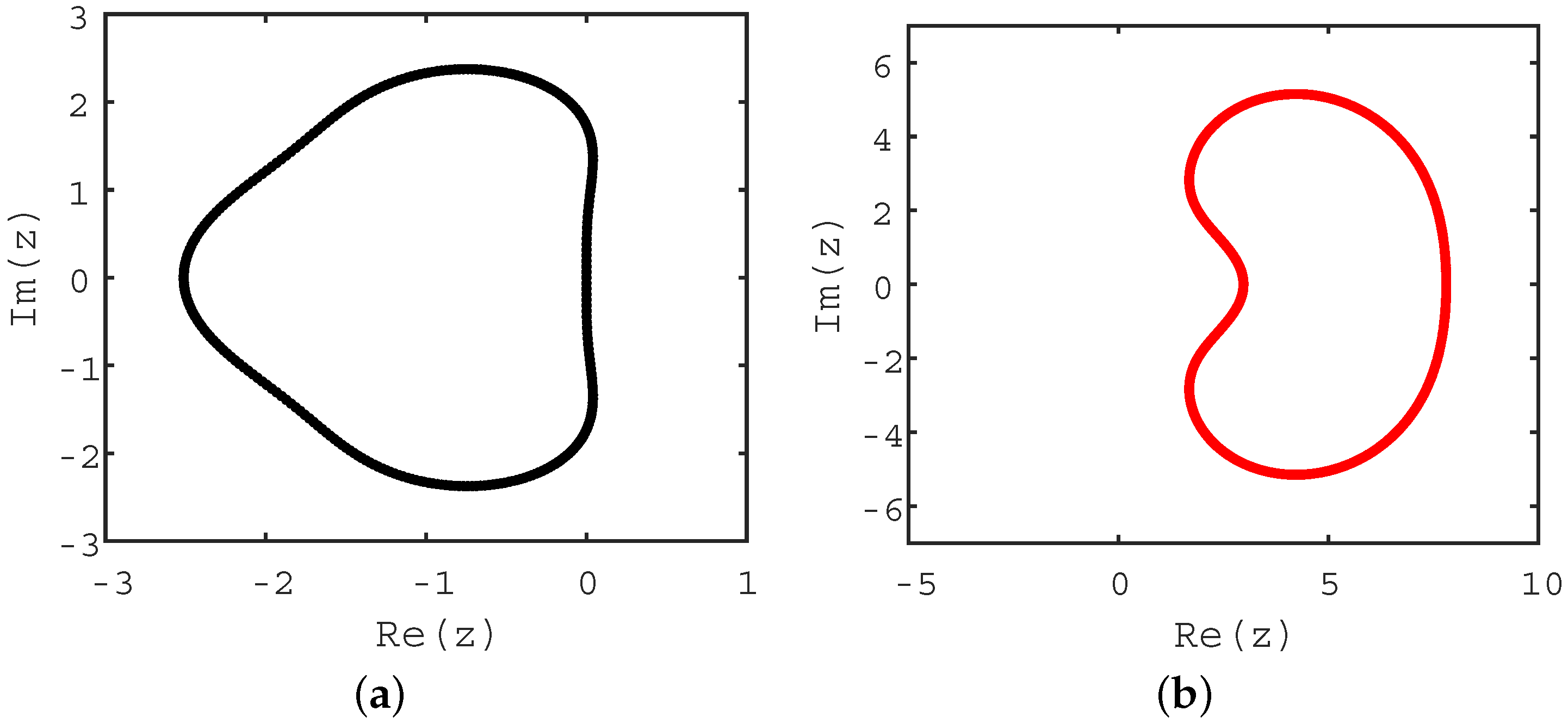
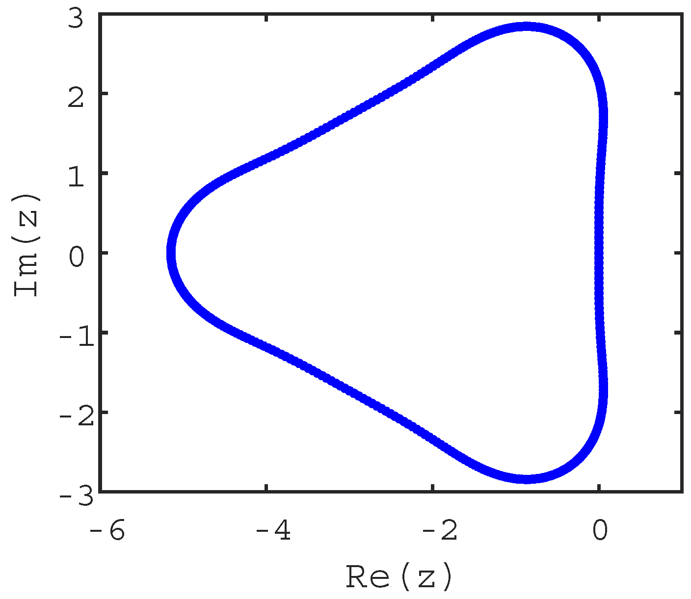
Appendix A, we provide the Butcher tableau of the SSP-RK3-4 scheme and plot its region of absolute stability. Compared with
Figure 2a, the stability region for the SSP-RK3-4 scheme is bigger. According to [
29], the available CFL number for the SSP-RK3-4 scheme is twice that for the SSP-RK3 scheme.
For our hybrid scheme, the time step length is decided by:
where
d denotes the spatial dimension of the problem,
takes the element length for 1D problems or the inscribed circle diameter of the element in 2D problems,
differs with the specific problem, and
and
are adjustable parameters. We take
, with
S defined in Equation (
21). For the SSP-RK3 scheme, the time step is decided by:
For the SSP-RK3-4 scheme, we set the time step two times as big as that for the SSP-RK3 scheme, i.e.,
4.1. 1D Linear Advection Problem
The problem is governed by:
and the boundary conditions are periodic. The analytic solution to the problem is
.
We numerically solve the problem with on three meshes, denoted by “Coarse 1D”, “Middle 1D”, and “Fine 1D”. During the mesh generation, the computational domain is divided into three regions: the left, the central and the right. The left and the right regions are symmetric with respect to the origin. The grids are uniformly distributed in the two regions. The range of the central region is kept four times the element size in the left/right region. In the central region, the grids are symmetrically distributed. The smallest element size in the central region is kept one-tenth of that in the left/right region, resulting in . In the central region, the ratio between the adjacent element sizes is kept less than 1.5. The biggest element sizes in Coarse 1D, Middle 1D, and Fine 1D are , , and , respectively.
Here are some remarks on the meshes. Generally the ratio between the adjacent element sizes should not exceed 1.2 in order to avoid big interpolation error. However, in the DG method, the high-order accuracy is achieved by increasing node numbers within the elements. There is no need to expand the stencil, as is done in the finite difference (FD) method or the finite volume (FV) method. In addition, as is shown in Equations (
6) and (
9), the DG solution is allowed to be discontinuous on element interfaces. The coupling between the local approximations is weak. Therefore, at least for the problems with smooth solutions, we believe the impact of the big element size change is endurable for the DG method. Last but not least, this kind of sudden jump in the size of element also appears in [
9]. See Figure 6a therein for reference.
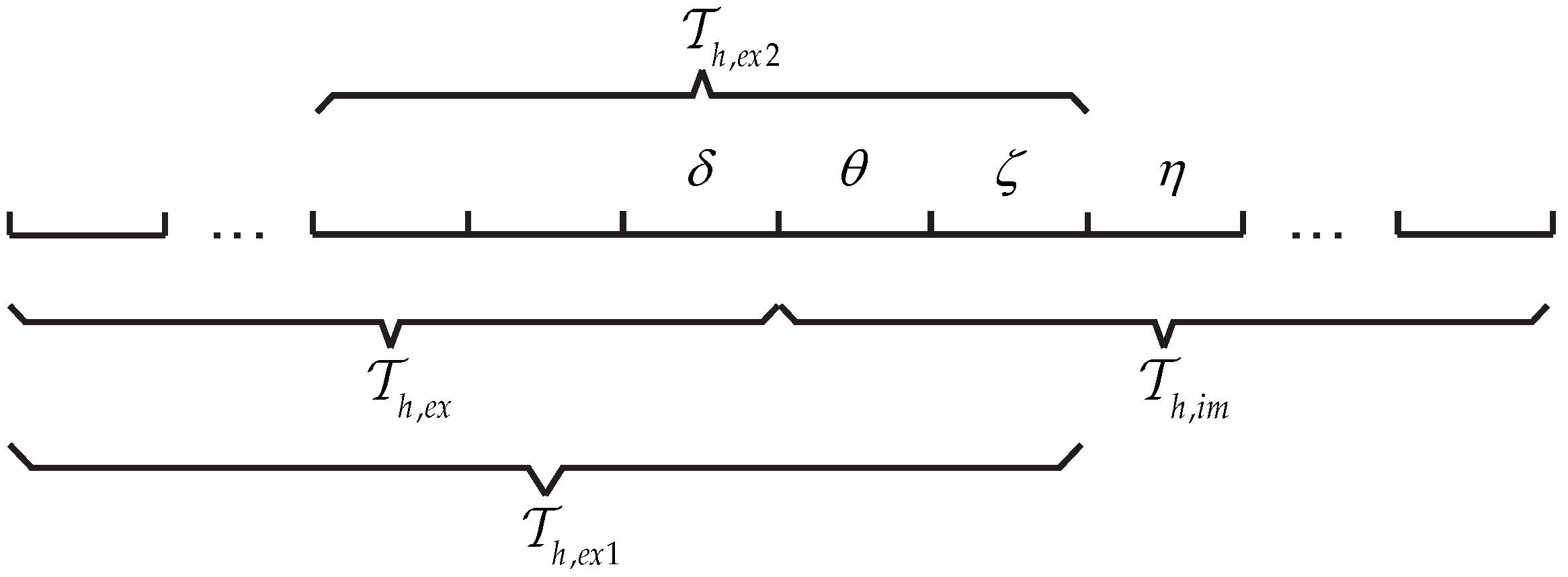
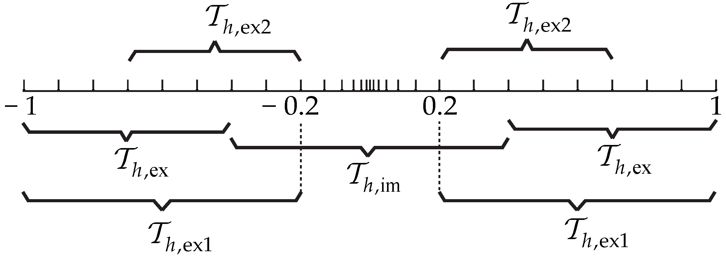
Figure 3 shows the Coarse 1D mesh and its elements grouping. The roles of
,
,
, and
during the temporal integration are same as in
Figure 1. Since the time step is restricted by the elements that subjected to the explicit integration, i.e., the elements in
, the outer two layers of elements in
are coarse. The elements groupings for Middle 1D and Fine 1D are similar to that for Coarse 1D.
For each calculation, we take
for local approximations. We spatially discretize the problem according to
Section 2. Since there is no diffusive item in the governing equation, we leave the diffusion-related items in the discretizations as zeros. For deciding the time steps, we take
,
,
and
. Each calculation is run up to
.
Table 1 shows the
error of the numerical result for each mesh and the convergence order of the errors. We found that the convergence order in space is
, which is optional for the DG method in solving conservation laws [
6]. According to [
6], to guarantee the domination of the spatial error, the accurate order for the time integration scheme is at least
. The optional convergence order in
Table 1 indicates that the hybrid scheme maintains the high-order accuracy of SSP-RK3 or LDIRK3. It also proves that the big size changes in the mesh has little effect on the accuracy of the method.
Table 2 compares the efficiency of the SSP-RK3 scheme (RK3), the SSP-RK3-4 scheme (RK3-4) and our hybrid scheme (hybrid). The second to the fourth columns show the average time step lengths for different schemes. The fifth to the last columns record the CPU time (in seconds) for the simulations. In accordance with Equations (
32)–(
34), the average time steps for the SSP-RK3-4 scheme and the hybrid scheme are twice and
S times as that for the SSP-RK3 scheme, respectively. On the other hand, the CPU time indicate that the acceleration of the computation does not scale linearly with the amplification of the time step. For the SSP-RK3-4 scheme, this is owing to the computation related to the extra fourth stage. For our hybrid scheme, this may comes from the nonlinear-solver-related calculations, e.g., constructing the Jacobian matrix and solving linear systems. Nevertheless, based on the given meshes, it is clear that the hybrid scheme is superior towards the SSP-RK3 scheme or the SSP-RK3-4 scheme in terms of efficiency.
4.2. 1D Linear Advection-Difussion Problem
The problem is governed by:
The analytic solution to the problem is
. The boundary conditions are applied using the analytic solution.
We numerically solve the problem with
and
. The meshes being used are same as in
Section 4.1.
is taken for the local approximations. The spatial discretization for the problem is the same as in
Section 2. To find the upper limit of
, we first apply the SSP-RK3 scheme. The definition of
is given by:
Through numerical tests, we find that the maximum of
for maintaining the calculation stability is 0.3. For defining the time step for the hybrid scheme, we take
,
,
. Each calculation is run up to
.
Table 3 shows the
errors of the numerical results and their convergence order. According to [
8] (p. 75), when the NIPG approach is selected for dealing with the diffusive item, the theoretical convergence order measured in
-norm is
when
N is odd. We found that the numerical results matched well with the theory.
Table 4 compares the efficiency of different schemes. Similar to the results in
Section 4.1, in every simulation, the hybrid scheme enjoyed the biggest available time step and consumed the least CPU time.
4.3. 1D Euler System
The problem is governed by:
where:
where
is the density,
u is the velocity,
p is the pressure, and
is the total energy. Here
.
We define the initial condition as:
and apply periodic boundary conditions. The analytic solution to the problem is:
The meshes being used are same as in
Section 4.1.
is taken for local approximations. During the spatial discretization, the Vijayasundaram flux [
31]:
is chosen as the inviscid numerical flux. The treatment for each equation of the governing system is similar to that in
Section 2. In our application, the ODEs pending to the temporal integration are:
where:
where
,
,
,
,
correspond to the
eth equation of the governing system. Their definitions are similar to that in Equation (
12).
When integrating Equation (
44) with the hybrid scheme, it is necessary to construct the matrix
. For the 1D Euler system,
consists of
blocks. The calculation for the
th block, i.e.,
, is similar to that in
Section 3.2.2. The matrices
and
are directly taken as the partial derivatives of
with respect to
and
, respectively. For defining time steps using Equations (
32)–(
34), we take
,
and
. The definition of
is:
where
is the speed of sound. Each calculation is run up to
.
Table 5 shows the
errors of the densities and their convergence order. We found that the optimal (
)th order is well attained.
Table 6 compares the available time step lengths and the CPU time for different schemes. Again the hybrid scheme enjoyed the biggest time step and the least CPU time.
4.4. 2D Euler System
The problem is governed by:
where:
In Equation (
48),
is the density,
u and
v are the velocity components,
p is the pressure, and
with
is the total energy. We consider an isentropic vortex problem with the analytic solution [
7] (p. 209):
It is used for defining the initial condition and boundary conditions for numerical simulations.
We solve the problem on three meshes, denoted by “Coarse 2D”, “Middle 2D”, and “Fine 2D”. In each mesh, the domain is divided into the surrounding region and the central region. The coarse elements in the surrounding region are made by diagonalizing the squares of same sizes. The central region is a square whose side length is kept two times the leg length for the coarse element. The elements in the central region are refined artificially. The smallest element length is kept one-eighth of that in the surrounding region, leading to . The ratio between the adjacent element sizes is kept less than 1.5 during the refinement. Since all elements within the mesh are are isosceles right triangles, the skewness (measured by the normalized equiangular method) for the mesh is constant 0.25 and the aspect ratio is . The biggest leg lengths in Coarse 2D, Middle 2D, and Fine 2D are 0.5, 0.25, and 0.125, respectively.
Here are some remarks concerning the quality of the 2D meshes. Similar to the 1D cases, we believe the impact of the radical size change is minimized by the independence of the local approximations in the DG method. In addition, the radical size jump in element size is common in relevant researches, see, e.g., Figure 8 in [
9], Figure 5 in [
11] and Figure 1c in [
12], for reference.
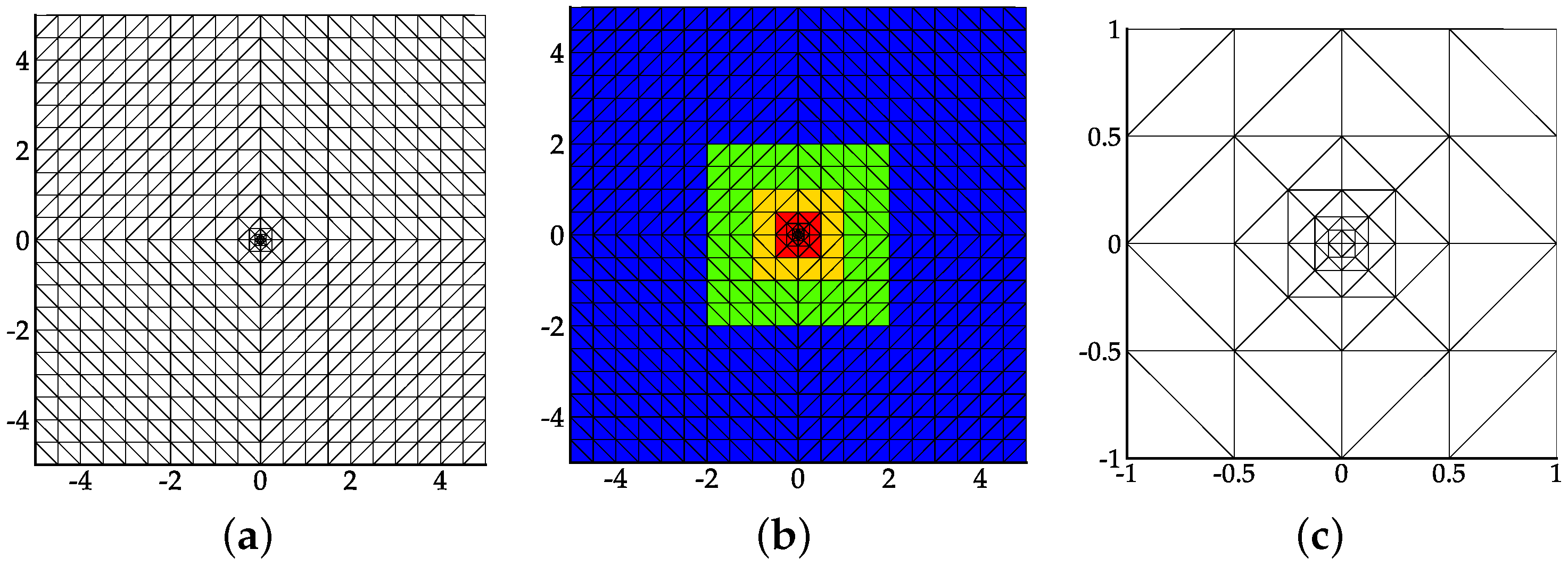
Figure 4 shows the Coarse 2D mesh and its elements grouping. The grouping strategy for the 2D elements is similar to the 1D case. The relationship between the color and the membership for an element is given in
Table 7. The elements groupings for Middle 2D and Fine 2D are similar to that for Coarse 2D.
For each calculation,
is taken for local approximations. The spatial discretization for the problem is similar to that in
Section 4.3. For defining time steps, we take
,
and
. The definition of
is:
where
and
. Each calculation is run up to
.
Table 8 shows the
errors of the densities and their order of convergence. Similar to the 1D cases, the optimal (
)th order for the DG method is achieved. It indicates that the high-order accuracy of the SSP-RK3 scheme or the LDIRK3 scheme is maintained by the hybrid scheme, and the impact of the big size changes in the mesh is negligible.
Table 9 compares the efficiency of different time integration schemes. The hybrid scheme performs even better in simulating 2D problems than in 1D problems. For each 2D simulation, the CPU time it took was merely one-third of that for the SSP-RK3 scheme or less than half of that for the SSP-RK3-4 scheme.
4.5. 2D Navier-Stokes System
The problem is governed by:
where
q,
f, and
g are defined same to Equation (
48) and:
where
In Equations (
52) and (
53),
u and
v are the velocity components,
is the viscosity coefficient,
is the heat conductivity, and
T is the temperature. To derive a dimensionless form of the governing system, we introduce a reference density
, a reference velocity
, and a reference length
.
defines a reference time,
defines a reference pressure, and
defines a reference temperature with
denoting the specific heat at constant volume. Normalizing Equation (
51) with the reference quantities and denoting the dimensionless quantities with the apostrophe, we obtain:
where
,
, and
are defined as:
and
and
are defined as:
where
In Equations (
56) and (
57),
is the reference Reynolds number and
is the Prandtl number. We take
and
for air. In our applications,
,
and
takes the cylinder diameter. The speed of sound is calculated by
and the subscript
∞ refers to the state of the free-stream.
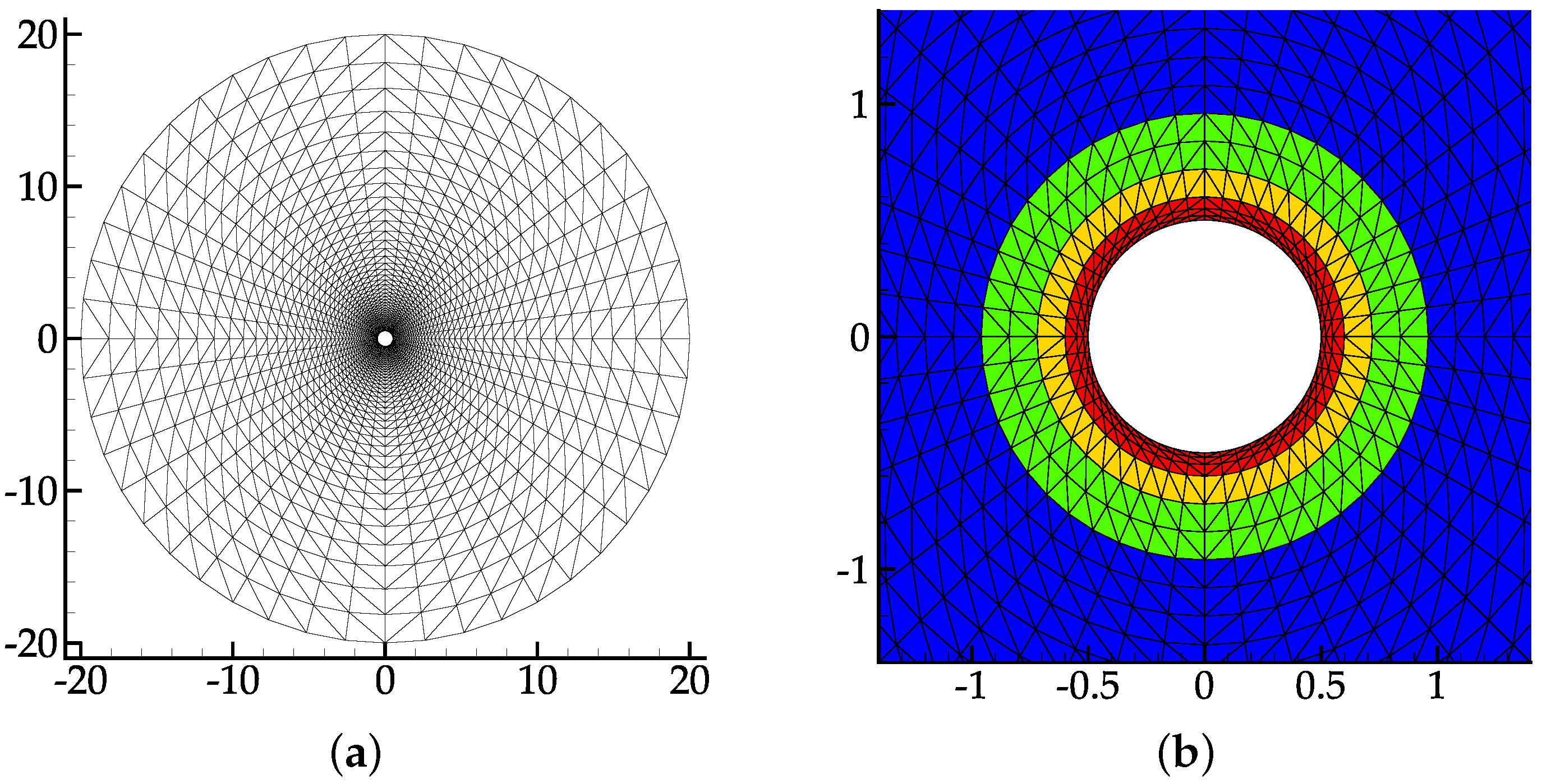
Figure 5a shows the mesh for the numerical simulation. It is generated in a way similar to that in Figure 14, [
9] and Figure 10, [
32]. The diameter for the outer boundary is 40 times as big as that for the cylinder. There are 3840 triangular elements in the mesh. They are achieved by diagonalizing
structured rectangular elements. The heights of the first five layers of elements adhering to the cylinder are 0.02, 0.03, 0.05, 0.12 and 0.12. In the first layer of elements, we achieve the maximum of the aspect ratio, 3.25, and the maximum of the skewness (measured by the normalized equiangular method), 0.72. The biggest size changes appear at the third and the fourth layers of elements, i.e.,
. Within the mesh, the maximum and minimum of
are 0.0607 and 0.0168, respectively, resulting in
.
Figure 5b presents the coloring of the elements. The coloring strategy is the same as in
Table 8.
In our computation, the state for the free-stream is defined by:
leading to
, with the Mach number calculated by
. Besides, the Reynolds number of the free-stream is set to
. To speed up the simulation, our computation consists of two periods. In the first period, we pursue the steady inviscid solution to the problem. That is, the flow is governed by the 2D Euler system, with
defining the initial condition. During the computation, characteristic boundary conditions [
33] and inviscid wall conditions are applied to the outer boundary and the cylinder surface, respectively. In the second period, the governing system for the problem is replaced by Equation (
54). The inviscid solution just obtained is used for initializing the flow. Characteristic boundary conditions and viscous wall conditions [
8] (p. 484) are applied during the remaining computation.
In our computation,
is taken for local approximations. The spatial discretization for the convective items are the same as that in
Section 4.4. The NIPG approach for treating the viscous items can be found in [
8] (pp. 486–491). To find the upper limit of
, we first integrate the DG discretization using the SSP-RK3 scheme, with the time step length defined by:
where:
where
,
, and
is the dimensionless element size.
Through numerical tests, we found that the maximum of
for maintaining the calculation stability is 0.8. Next, the hybrid scheme with
is used for the time integration. The fixed time step length is close to one obtained by Equation (
32) with
,
and
.
According to the direct numerical simulations (DNS) results in [
34] and the experimental results referred to therein, the flow is unsteady with
and
. Over time, vortices periodically shed from the cylinder, causing fluctuations in the physical quantities in the wake of the cylinder.
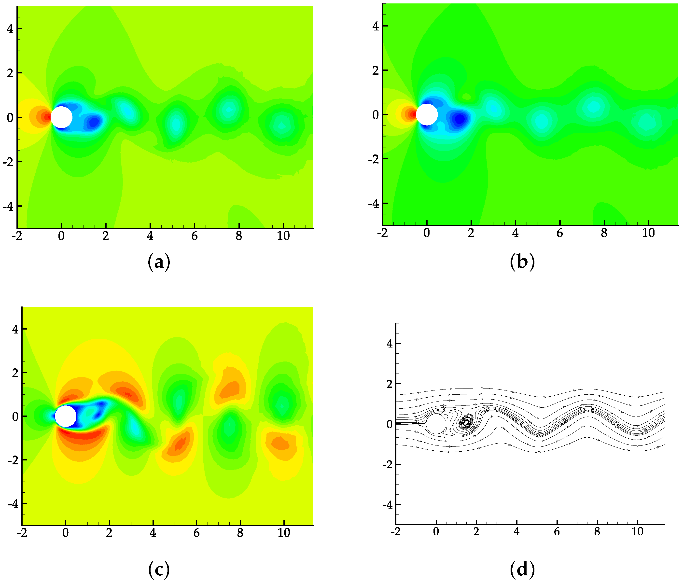
Figure 6 shows the numerical results at
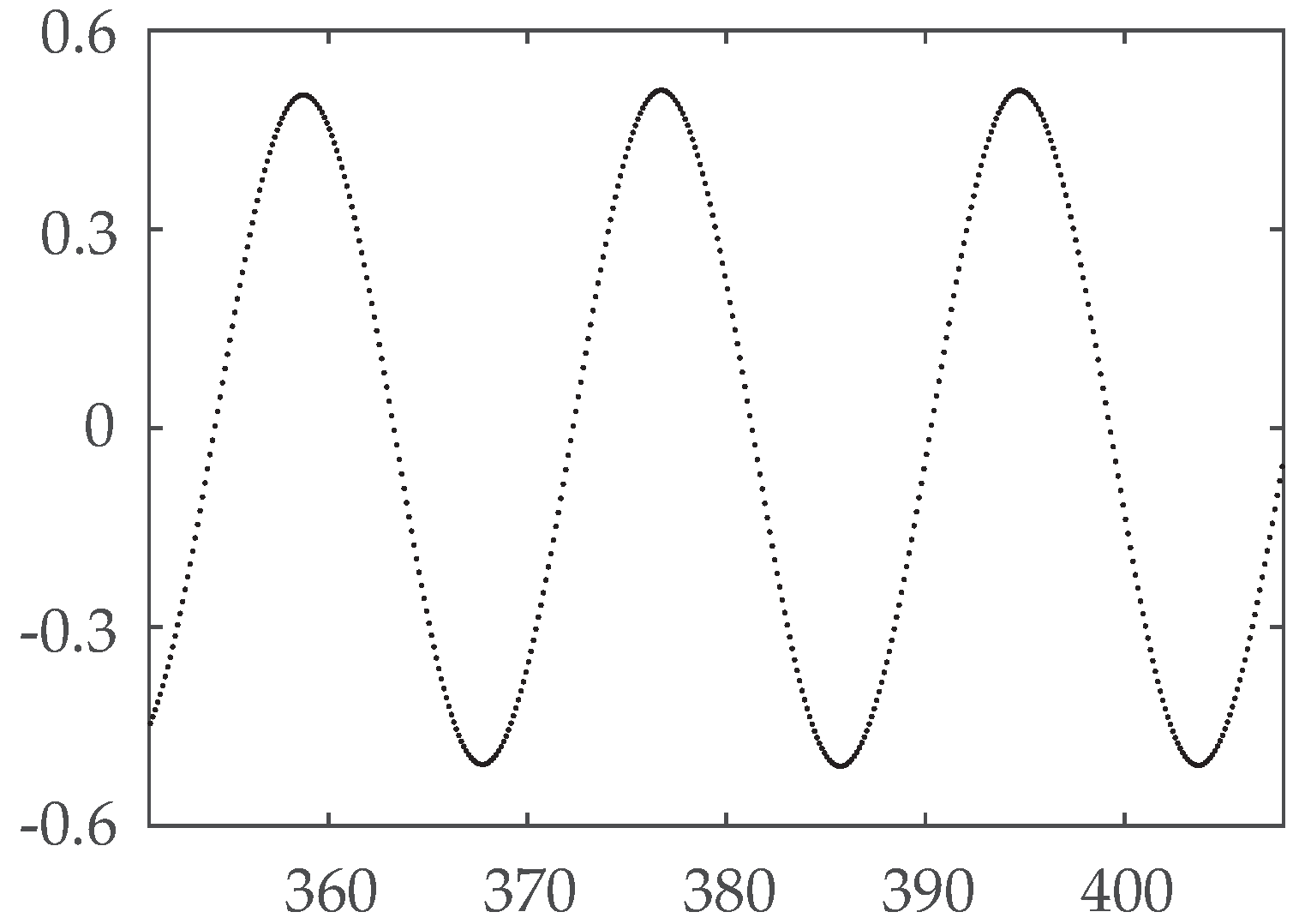
. The fluctuations in the fields and the bending of the streamlines indicate that the shedding of vortices has been set up well. During the calculation, the lift coefficient
of the cylinder is recorded every 50 time steps. The time history for
from
to
is shown in
Figure 7. It can be found that the fluctuation period of
is
.
Table 10 compares our numerical results with that in reference [
34]. The matches between the two sets of results illustrate the usefulness of the hybrid scheme.
Table 11 presents the available dimensionless time step length and the CPU time (in seconds) cost per time step for each scheme. After dividing the CPU time with the time step length for each scheme, we got the required CPU time for the simulation corresponding to unit dimensionless time, i.e., 2985 s for the SSP-RK3 scheme, 1923 s for the SSP-RK3-4 scheme and 1480s for our hybrid scheme. It is clear that the hybrid scheme performs best in terms of efficiency.


