1. Introduction
Photovoltaic (PV) power generation has become very widespread throughout the world, because of its advantages such as lesser maintenance, absence of moving parts, which eliminates the noise effect, low cost, and increasing efficiency of the equipment in PV systems (such as power electronic converters). However, the major drawback of PV systems is their high dependence on solar irradiance and temperature [
1]. Current-Voltage (I-V) and Power-Voltage (P-V) characteristic curves of PV panels are non-linear. There is an optimum power point called the maximum power point (MPP) on the curves, and a PV panel generates maximum output power at the MPP. In addition, the MPP on the characteristics curve is influenced by solar irradiance and temperature. To extract maximum available power from a PV panel, a DC-DC converter is controlled by the maximum power point tracking (MPPT) method in order to operate the panel at MPP [
2].
To date, various studies have been conducted aiming to increase the efficiency of the MPPT methods on PV systems.
Tian et al. [
3] presented a modified asymmetrical variable step size incremental conductance (INC) MPPT method that is based on the asymmetrical feature of the P-V curve. The proposed algorithm compared with the conventional fixed or variable step size method. The authors stated that the proposed algorithm improved tracking accuracy and speed. Soon and Mekhilef [
4] proposed a simpler fast-converging maximum power point tracking technique which used the relationship between the load line and the I-V curve. The results were compared with the conventional INC MPPT method and it was shown that the proposed algorithm was four times faster than the conventional INC MPPT method during the load and solar irradiation variation. Dogmus et al. [
5] proposed an MPPT algorithm with proportional-integral-derivative (PID) optimization based on particle swarm optimization (PSO) for single MPP PV systems, in order to increase the performance of the perturb and observe (P&O) MPPT algorithm. The proposed MPPT algorithm was compared with a conventional PID controller and the P&O MPPT algorithm in order to test its tracking performance for MPP. The authors stated that the tracking performance of MPP increased from 96.7% to 99.0%.
Loukriz et al. [
6] proposed a new variable step size incremental conductance (INC) MPPT method. Under similar operating conditions, INC MPPT methods with variable step size and fixed step size were compared. Comparative results showed that the proposed method tracks the maximum power point with less power oscillation. Liu et al. [
7] proposed a modified variable step size INC MPPT method that automatically adjusts the step size for MPP. The proposed method was compared with the classical fixed step size method. The proposed method has simultaneously improved the MPP tracking speed and tracking accuracy.
Kececioglu et al. [
8] proposed a Type-1 fuzzy–PI controller for maximum power point tracking. To validate the performance of proposed controller, a simulation model was realized by using the Matlab/Simulink environment. The proposed controller was compared with the conventional PI controller. The proposed Type-1 fuzzy-PI controller has superior performance compared to a conventional PI controller under varying atmospheric conditions.
Yilmaz et al. [
9] improved a new MPPT method using adapting calculation based on Type-1 fuzzy logic controller. The proposed MPPT method tested by the simulations on Matlab/Simulink under variable atmospheric conditions and compared with the performance of the P&O, INC, and conventional FLC respectively. The authors concluded that the proposed MPPT method has better performance than other methods to determine MPP. Palaniswamy and Srinivasan [
10] presented a Takagi-Sugeno (T-S) fuzzy-based MPPT algorithm for a standalone photovoltaic system. The algorithm presented was validated using Matlab/Simulink under various operating conditions and compared to the INC algorithm. The authors stated that the effectiveness of the proposed T-S fuzzy algorithm in tracking maximum power was better than the INC algorithm. Rezk et al. [
11] proposed an adaptive Type-1 fuzzy logic controller-based new MPPT methodology for controlling PV systems. The authors emphasized that main advantage in the proposed method is accurate and adaptive tracking performance of the operating maximum power extraction point of the PV system, and the mitigation of power fluctuations in transient and steady state operating points. Ozdemir et al. [
12] presented a Type-1 fuzzy logic based MPPT method for quadratic boost converter. The method presented was validated by using simulation and experimental studies. Altin [
13] presented an MPPT method based on an Interval Type-2 fuzzy logic controller. The author tested the proposed method using Matlab/Simulink and stated that the proposed method provides fast dynamic response under rapidly changing atmospheric conditions.
Danandeh and Mousavi [
14] proposed a hybrid MPPT method based on Type-1 fuzzy logic that is combined with the INC algorithm. The proposed hybrid MPPT method was tested under standard and changing conditions, and compared with the conventional Type-1 fuzzy logic controller and INC algorithm. Results showed that the proposed hybrid MPPT method exhibits good behavior under stable and fast-changing conditions. Shiau et al. [
15] presented a comparative study on fuzzy logic-based solar power MPPT algorithms using different fuzzy input variables. The authors concluded that the range of the input variable of the angle of incremental conductance (AIC) algorithm is finite and the maximum power point condition is well defined in a steady condition and, therefore, it can be used for multipurpose controller design.
When the literature on MPPT methods based on the fuzzy logic controller was examined, it was observed that the Interval Type-2 Takagi Sugeno Kang fuzzy logic controller (IT2-TSK-FLC) and AIC MPPT algorithm have not been combined for this purpose, despite the advantages of the AIC MPPT algorithm and Interval Type-2 Takagi Sugeno Kang (TSK) fuzzy logic system. In this paper, a hybrid control structure that is called AIC-IT2-TSK-FLC, based on the AIC MPPT algorithm and Interval Type-2 Takagi Sugeno Kang fuzzy logic controller is proposed for the MPPT of a PV system.
The main contributions of this study are listed below:
A new intelligent hybrid controller that is combined AIC MPPT algorithm and Interval Type-2 TSK fuzzy logic controller is proposed.
The AIC algorithm is selected to generate the error function of Interval Type-2 TSK fuzzy logic controller.
Interval Type-2 TSK fuzzy logic controller is preferred to handle the uncertainties in solar irradiances and temperature.
The exact duty cycle of the DC-DC converter is adjusted by proposed hybrid controller.
The proposed hybrid controller is studied under stringent solar irradiances and temperature profiles via detailed simulation and experimental studies.
The proposed hybrid controller can handle as possible abnormal conditions and improves the efficiency, tracking accuracy, and reduce the steady-state power oscillation.
Unlike many existing MPPT methods, the proposed hybrid controller has high adaptation ability for a new operating point at any time.
The present paper is organized as follows. The proposed hybrid control structure is given in
Section 2. The dynamic performance of the AIC MPPT method and proposed hybrid controller are compared with detailed simulation studies in
Section 3. The dynamic performance of the proposed hybrid controller is analyzed with experimental studies in
Section 4. Finally, the conclusions of the study are explained in
Section 5.
2. Proposed Hybrid Control Structure
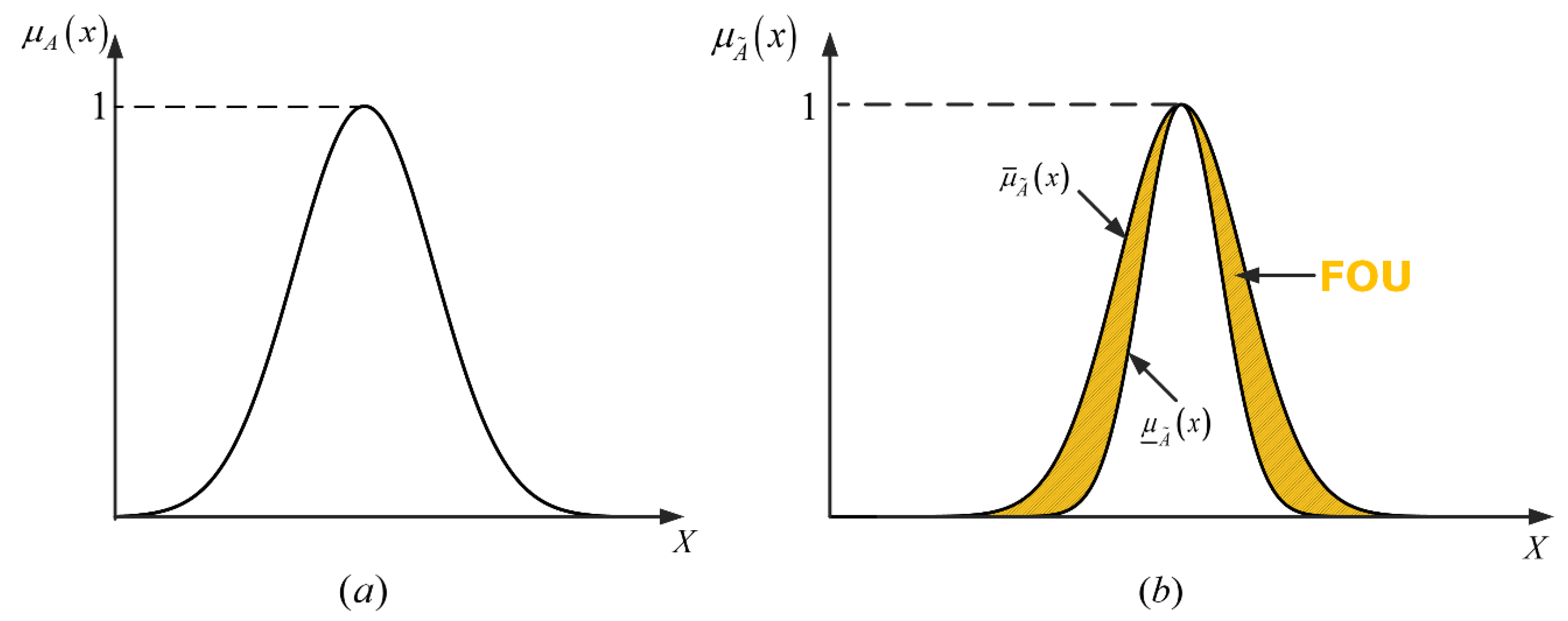
Introduced by Lotfi A. Zadeh in 1975, Type-2 fuzzy sets are an extension of Type-1 fuzzy sets. A Type-1 fuzzy set with x ∈ X and a single variable can be represented as follows:
The Type-1 fuzzy set given in Equation (1) does not have any uncertainties. In other words, each x input has a certain membership value between 0–1. If the membership degree of a variable is not known, a Type-2 membership function should be used instead [
16]. Type-1 and Type-2 Gaussian fuzzy sets are shown in
Figure 1.
Fuzzy logic control (FLC) is a widely-used method to perform MPPT for the PV system. Numerous studies [
17,
18,
19,
20,
21,
22,
23,
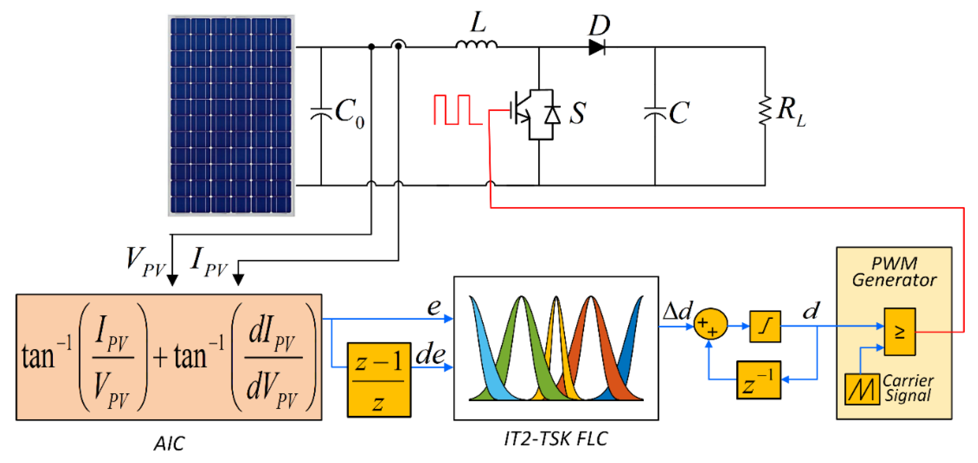
24] in the existing literature have demonstrated that Type-1 FLC (T1FLC) does not succeed in highly uncertain situations in the system, while a Type-2 FLC using Type-2 fuzzy set display better performance. In the present paper, a hybrid control structure called AIC-IT2-TSK-FLC was developed for MPPT of the PV system with a combination of the AIC MPPT algorithm and Type-2 FLC [
25]. The proposed hybrid control structure is shown in
Figure 2.
It can be seen
Figure 2 that the proposed hybrid control structure was applied to the PV system consisting of a PV panel and DC-DC power converter. The boost converter topology was selected in this study. Instantaneous voltage (V
PV) and current (I
PV) were measured on the PV panel using voltage and current sensors. The AIC MPPT algorithm was used to generate the error function of IT2-TSK-FLC responsible for the minimization of the error of MPP. The rate of change in the duty cycle (
) was provided by the IT2-TSK-FLC. The rate of change value of the duty cycle was summed with its previous value, in order to obtain the duty cycle of the converter (d). The output of the proposed hybrid control structure was applied to the switching device in the DC-DC boost converter. The control signal, which is the output of IT2-TSK-FLC, was generated using Type-2 fuzzy sets. A Type-2 fuzzy set consists of triples
:
where x ∈ X, a primary membership value, u ∈ J
x (J
x is the range of primary membership for a given x) and a secondary membership,
, for each member of domain, can be defined as follows:
The footprint of uncertainty (FOU) shown in
Figure 3 is the limited domain representing the primary uncertainty of the Type-2 fuzzy set between upper (
) and lower (
) membership functions. The FOU domain between upper and lower membership functions in the Type-2 fuzzy set was assumed to be an infinite Type-1 membership function. While general Type-2 fuzzy sets preserve their main properties, interval Type-2 fuzzy sets are introduced as an alternative in order to reduce the computational burden [
26]. When all
is equal to 1,
is an Interval Type-2 fuzzy set. Interval Type-2 fuzzy sets can be defined as follows:
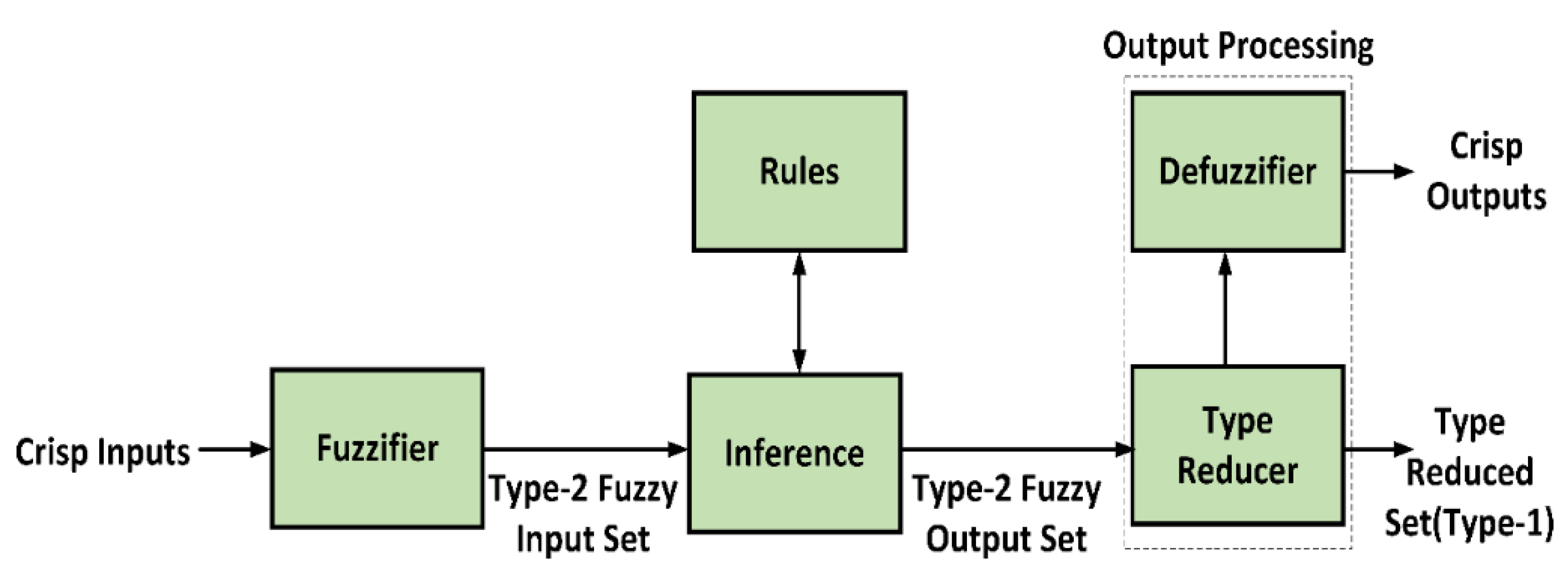
Both general and Interval Type-2 fuzzy logic membership functions are three dimensional. The only difference between them is that the secondary membership function value of an Interval Type-2 fuzzy logic function is equal to 1. Therefore, the computational time of these sets is shorter compared to the general Interval Type-2 fuzzy logic controller (IT2-FLC). IT2-FLC consists of four main parts: fuzzification, rule base, fuzzy inference, and type reducer [
27]. The main difference between IT2-FLC and the Type-1 fuzzy logic controller is type reduction. Type-2 fuzzy sets can be converted to Type-1 fuzzy sets thanks to type reduction. The output of the type reduction block is a Type-1 fuzzy set. All of the Type-1 fuzzy sets obtained were converted to crisp outputs thanks to the defuzzifier. The internal structure of IT2-TSK-FLC is shown in
Figure 4.
As shown in
Figure 4, crisp inputs were fuzzified with Type-2 input membership functions, then the fuzzy inference engine generated the controller signal according to the input values, membership functions, and rule base. After the type reducing and defuzzifying processes, crisp values of the IT2-TSK-FLC were obtained. The proposed IT2-TSK-FLC inference mechanism was defined in three different models as A2-C1, A2-C0, and A1-C1. The A2-C0 TSK model was used in the inference mechanism of IT2-TSK-FLC in the present study. The antecedents are Type-2 fuzzy sets, while the consequents are first-order polynomials in the A2-C0 TSK model. The A2-C0 TSK model can be defined by fuzzy If-Then rules [
28]. The A2-C0 TSK rule base can be defined as follows:
where
= 1,2,….,25 represents rule numbers;
,
are input variables (e, de);
and
are membership functions;
is the rule output;
,
,
are the consequent parameters. Gaussian type membership functions are preferred due to their smoothness and nonzero at all points on the control algorithm. This also will affect the power accuracy of systems under the steady-state response. [
29]. For that reason, the Gaussian type membership function was selected. The mathematical equations for the Gaussian type membership function are given in Equations (5) and (6).
where
denotes the degree of membership for input variable, represents the mean value of function, is standard deviation and x
i is the input variable [
30]. IT2-TSK-FLC has two inputs (e, de) and single output (
) which is rate change of duty cycle for DC-DC converter.
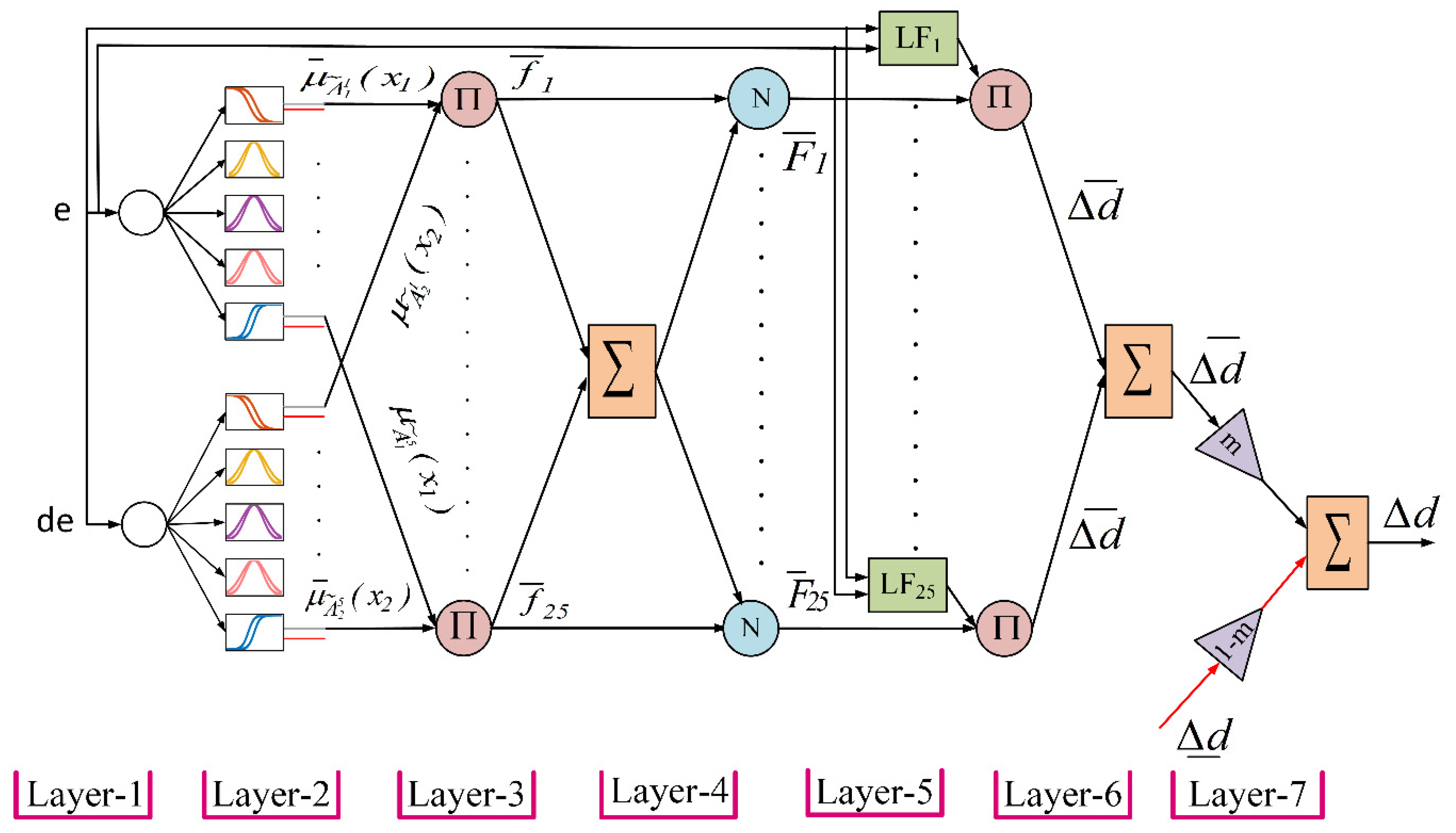
Design Specifications of Interval Type-2 TSK-FLC
The detailed structure of IT2-TSK-FLC is shown in
Figure 5. As shown in
Figure 5, the IT2-TSK-FLC configuration consists of seven layers.
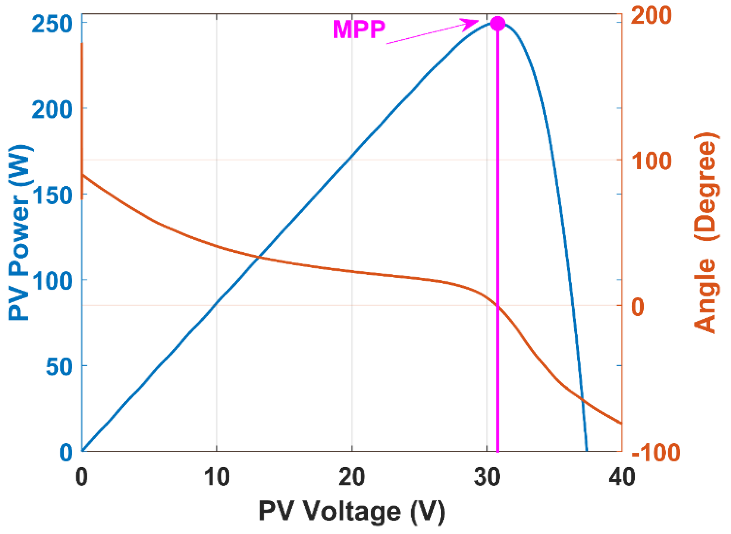
Layer-1: This layer is the input layer. As seen in
Figure 1, the inputs of controller (e, de) is generated by the AIC MPPT algorithm, described in Equation (7). The characteristic curves of the AIC MPPT algorithm are shown in
Figure 6. As seen in
Figure 6, the angle is equal to zero around the MPP point.
Layer-2: In this layer, the degrees of the membership functions are determined for inputs. The membership functions of the input and the rule base of the proposed hybrid control structure must be identified according to the MPP condition for the IT2-TSK fuzzy inference system. The membership functions are labeled with negative big (NB), negative small (NS), zero (ZE), positive small (PS), and positive big (PB). The membership functions are determined for error (e) and change of error (de) of the proposed hybrid control structure. Input membership functions are scaled to the range (−1, +1). Five gaussian membership functions designed for the inputs are shown in
Figure 7.
Layer-3: The third layer of the IT2-TSK-FLC consists of the nodes indicated by Π. The firing strengths of the fuzzy rules are defined as lower and upper using the product operator. The fuzzy rules of the proposed hybrid control structure are given
Table 1. The mathematical equations of Layer-3 are given below:
Layer-4: This layer is also known as the normalization layer, and each node is labeled as N. Normalization is performed by proportioning the firing strength of each node rule to the sum of the firing strengths of all rules. The normalization process is defined as follows:
Layer-5: This is a linear function (LF) layer. The LF outputs are calculated according to the rule base. Layer outputs are computed as follows:
Layer-6: The multiplication of membership degrees for upper and lower membership functions and linear functions are obtained in this layer.
Layer-7: Biglarbegian-Melek-Mendel (BMM) method is a closed-form type reduction and defuzzification method used in this layer [
31]. The closed mathematical form of type reduction and defuzzification process for the proposed hybrid controller are calculated as follows:
3. Simulation Studies
In this section, we describe the simulation of the proposed hybrid controller for MPPT using the MATLAB/Simulink environment and Sim Power System Toolbox. To evaluate the performance of the proposed hybrid controller under the various environmental conditions, simulation studies were also performed under different operation conditions, described as follows:
Case 1: In this case, solar irradiance and panel temperature values were set to standard test condition (STC) values of 1000 W/m2 and 25 °C. Thus, steady state and transient performances of the proposed hybrid controller were evaluated for STC.
Case 2: In this case, the performance of the proposed hybrid controller was analyzed against input disturbance under extreme environmental conditions.
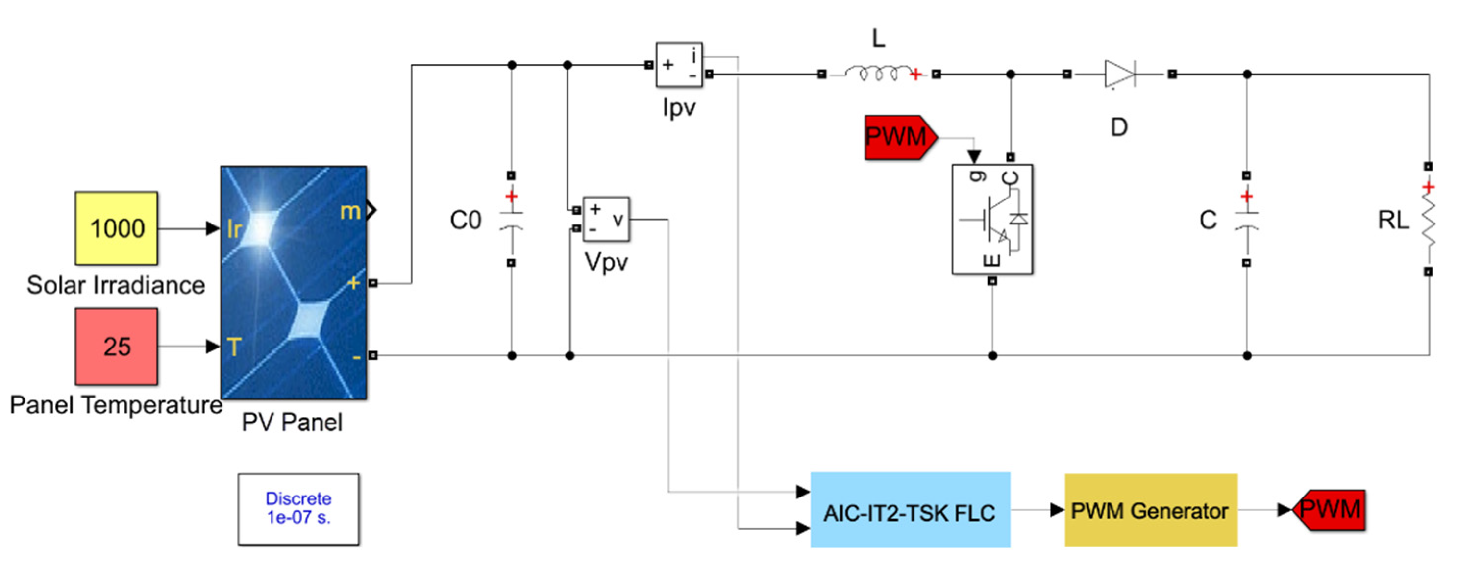
3.1. PV System and Converter Modelling
A PV panel that had a single MPP was used for PV simulation modeling. The MPP value of the PV panel at the STC was 250 W. Electrical characteristic parameters of the PV panel are listed in
Table 2. The DC-DC converter values selected for simulation studies are given in
Table 3. The modeled system using MATLAB/Simulink is shown in
Figure 8.
3.2. Simulation Results
3.2.1. Case 1
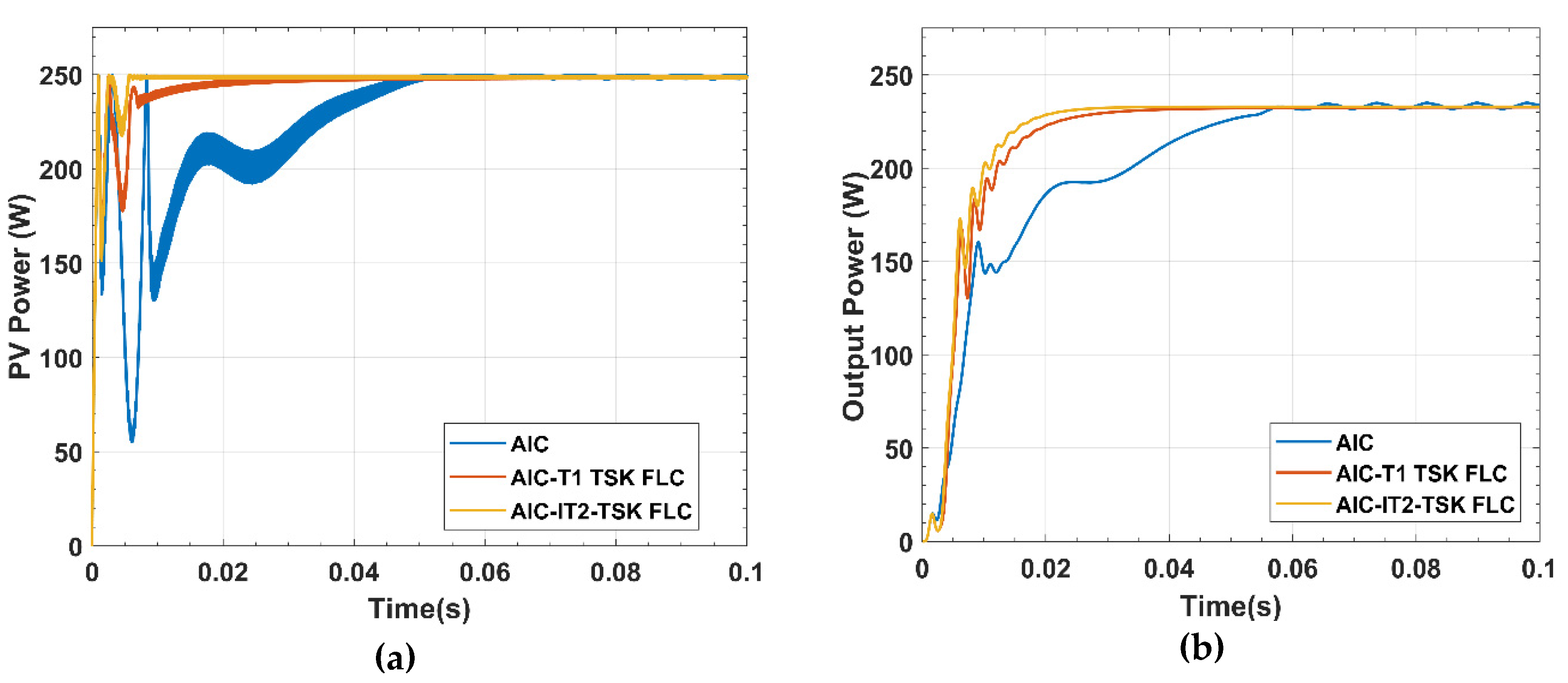
In this part of the simulation studies, the performance of the proposed hybrid controller was analyzed under STC. Simulation results for output power of a PV panel and DC-DC converter obtained from AIC-IT2-TSK-FLC were compared with conventional AIC MPPT method and AIC Type-1 TSK-FLC (AIC-T1-TSK-FLC), which is one of the existing fuzzy control methods
Total simulation time was 0.1 s for this case. Simulation results are shown in
Figure 9. It can be noted that the settling times of the proposed hybrid control structure, AIC-T1-TSK-FLC, and AIC MPPT method were 5 ms, 20 ms, and 52 ms respectively. Maximum power extracted from the PV panel of the proposed hybrid controller, AIC-T1-TSK-FLC hybrid controller, and conventional AIC MPPT method following the settling times were 249.6 W, 248.9 W, and 248.2 W respectively.
As shown in
Figure 9b, DC-DC converter output powers of IT2-TSK-FLC, AIC-T1-TSK-FLC, and AIC MPPT were 232.9 W, 231.5 W, and 230.3 W respectively. It is evident that unlike the conventional AIC MPPT method, the proposed hybrid control structure was reduced to oscillation on the PV panel and converter output power. According to converter design considerations, the power conversion efficiency of the DC-DC converter was equal to 93.31%, which is acceptable for boost converter design.
Performance comparison of all MPPT controllers are presented in terms of performance parameters in
Table 4.
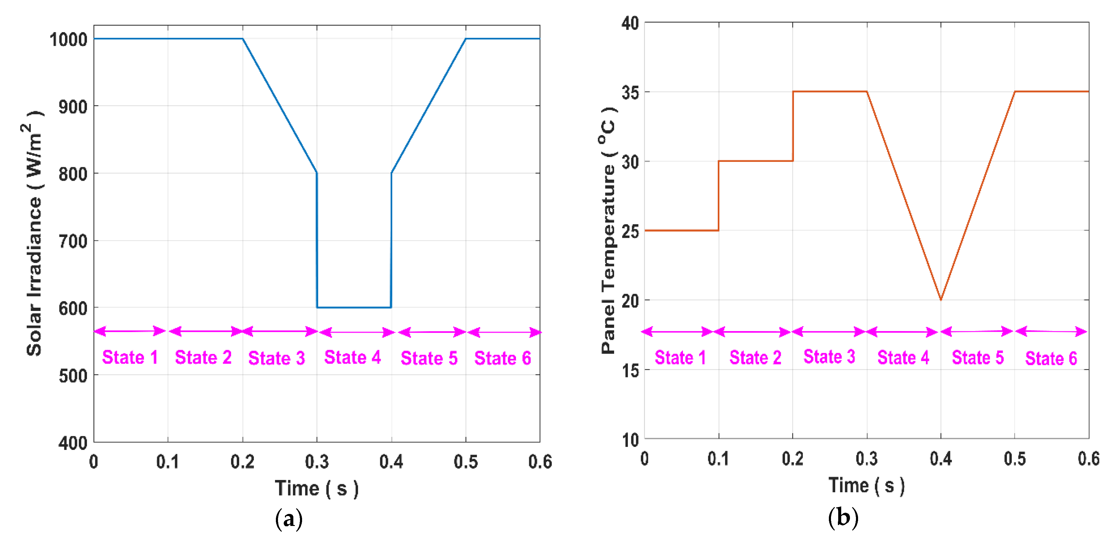
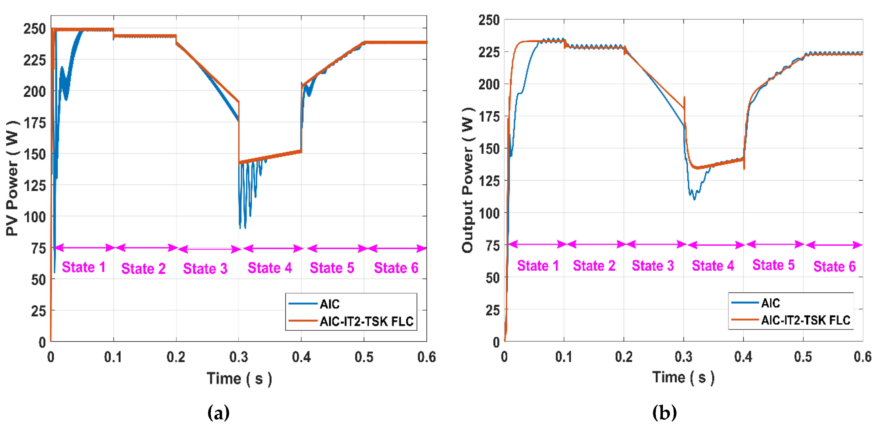
3.2.2. Case 2
This case was separated into six states in order to evaluate the performance of the proposed hybrid controller against extreme environmental conditions. At the first state, solar irradiance and panel temperature values were fixed at 1000 W/m
2 and 25 °C, respectively. In the second state of the case, the solar irradiance value was fixed at 1000 W/m
2 and the panel temperature value was stepped up from 25 °C to 30 °C. Subsequently, the solar irradiance value was linearly decreased from 1000 W/m
2 to 800 W/m
2, and the panel temperature value was fixed at 35 °C during this state. In the fourth state, the solar irradiance value was stepped down from 800 W/m
2 to 600 W/m
2. Similarly, the panel temperature value was linearly decreased from 35 °C to 20 °C. In the fifth state, the solar irradiance value and panel temperature value were increased throughout this state. In the last state, the solar irradiance value was fixed at 1000 W/m
2, and the panel temperature value was fixed at 35 °C. Total simulation time was 0.6 s. Extreme environmental conditions generated for this simulation are shown in
Figure 10. Simulation results are given in
Figure 11.
As seen in
Figure 11a, in the first state, PV power with the proposed hybrid control structure is 249.4 W, while PV power with the conventional AIC MPPT method was 247.9 W. The settling times of the proposed hybrid controller and AIC MPPT method were 8 ms and 55 ms, respectively. In the second state, PV power with the AIC MPPT method was stepped down to 242.2 W and PV power with the proposed hybrid control structure was stepped down to 244.2 W. Moreover, as shown in
Figure 11b, the oscillation of the output power of DC-DC converter was greatly reduced by the proposed hybrid controller. In addition, the conventional AIC MPPT method displayed poor MPP tracking performance and a long transient response, particularly under extreme environmental conditions. At the same time, the conventional AIC MPPT method caused more power losses compared to the proposed hybrid controller in the steady state condition for all states. Since power losses around the MPP reduce tracking accuracy, the MPP tracking accuracy of the proposed hybrid controller was better than the conventional AIC MPPT method. Moreover, continuous oscillations that occur in steady-state conditions of converter output power were eliminated by the proposed hybrid controller.
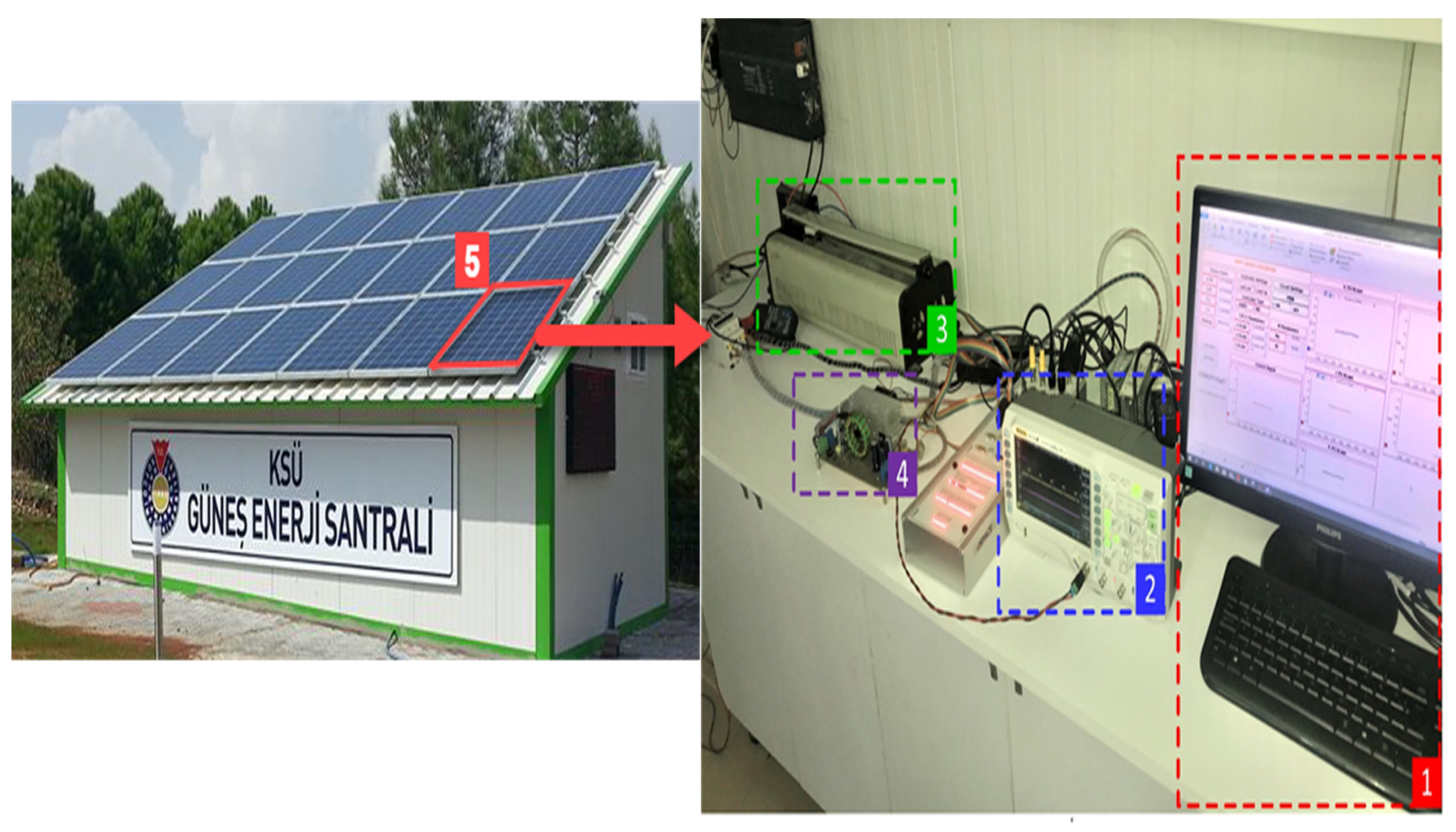
4. Experimental Studies
In this section, the implemention of the proposed hybrid control structure using an experimental setup based on dSPACE DS1104 which can work in real time with MATLAB/Simulink environment is described. A panel that is located in the roof of a real PV plant and installed standalone was used to evaluate the performance of the proposed hybrid control structure under real environmental conditions. The real view of the PV plant and the photograph related to the experimental setup of MPPT based on AIC-IT2-TSK-FLC is shown in
Figure 12. As seen in
Figure 12, the part of the experimental setup marked as “1” was the interface of the ControlDesk software. The ControlDesk software was used to display the measured parameters both graphically and numerically in real-time. The other parts of experimental setup, which were a digital oscilloscope, a DC-DC boost converter, a resistor, and a PV panel are marked as “2”, “3”, “4”, “5” in
Figure 11 respectively. In addition, a schematic presentation of the experimental study is given in
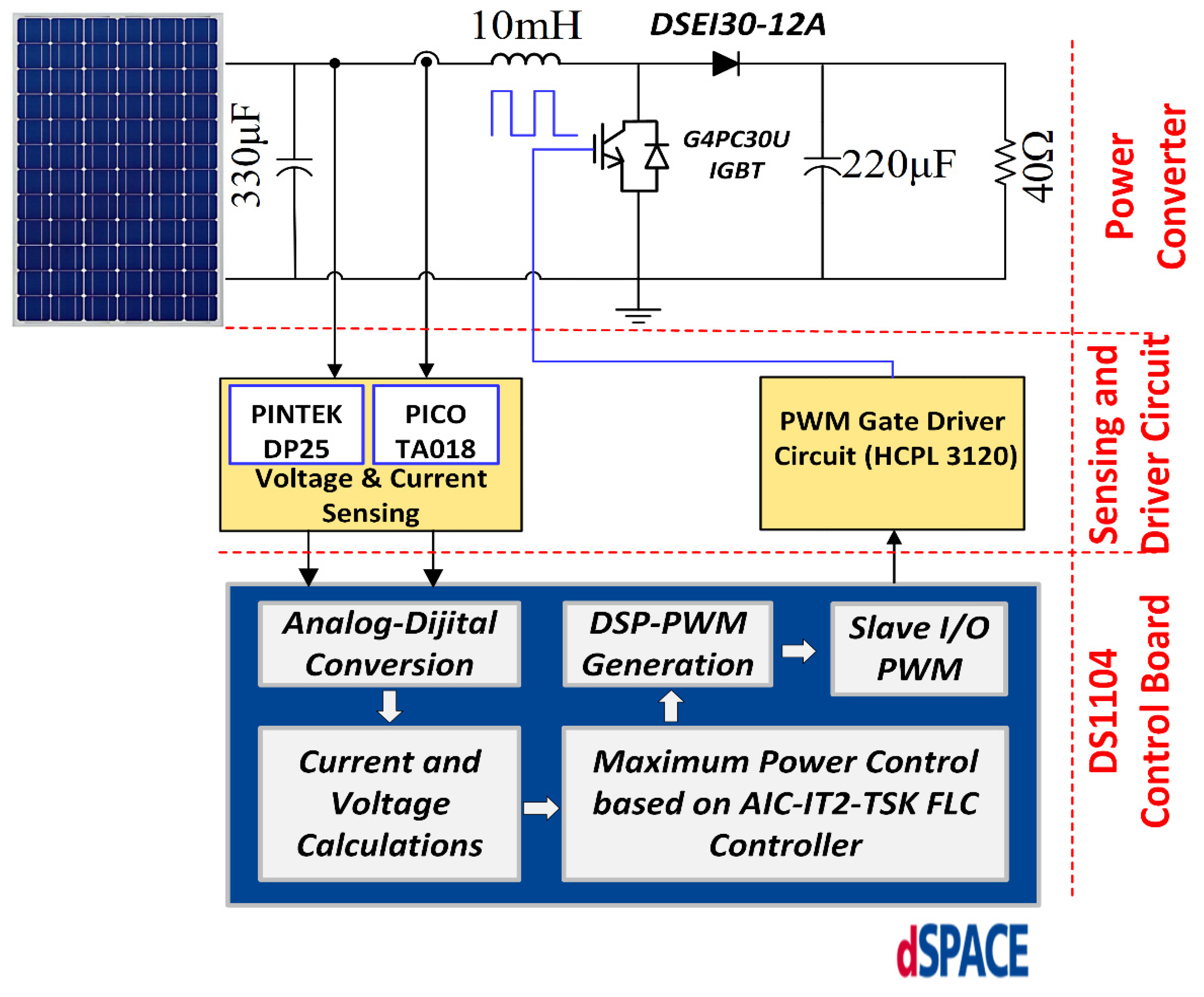
Figure 13.
As seen in
Figure 13, voltage and current sensing devices must have a high level of accuracy and sensitivity for hardware implementation of MPPT. Therefore, PICO TA018 current probe and PINTEK DP-25 voltage probes were used to measure current and voltage values of PV panel. In addition, pulse width modulation (PWM) signals received from the DS1104 control board must be amplified for switching devices. For this purpose, an isolated PWM gate driver circuit based on HCPL 3120 optocoupler was designed in the present study. This optocoupler was preferred to it has a more stable output in higher switching frequencies. The real-time interface (RTI) model designed for the experimental study is shown in
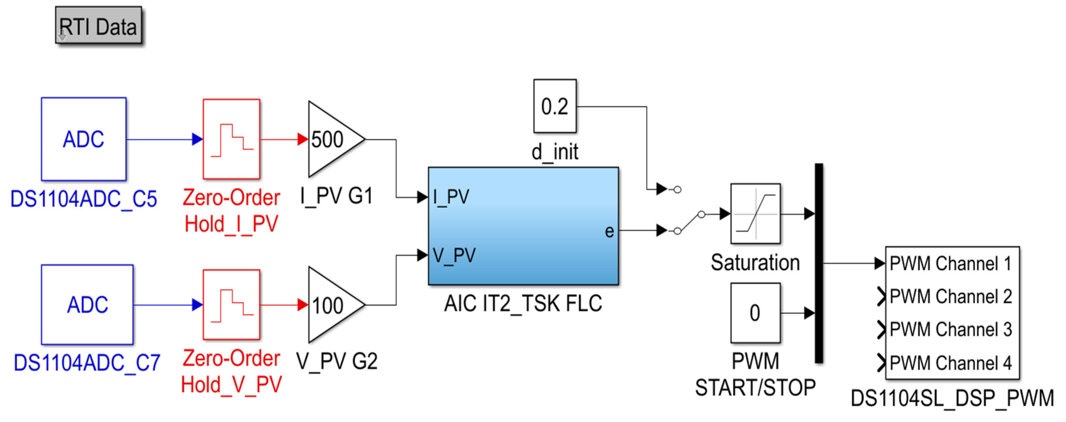
Figure 14. The control algorithm required for real-time operation has been implemented by this model.
As shown in
Figure 14, current and voltage values of the PV panel were measured using probes and applied to analog-digital converters (ADC) of the DS1104 controller card. The current and voltage values obtained from ADC block were converted into their real values in the calibration units, and then they were applied to the ‘AIC-IT2-TSKFLC’ block. After the controlling process was finished, PWM signals were sent to the driver circuit. The saturation block on the RTI model was used as software protection for the duty cycle of the PWM signal. The lower and upper limits of this block were set 0.2 and 0.8 respectively. Then, these signals were applied to IGBT for the switching process. Sampling time was taken as 100 µs for the RTI model. The experimental study was performed on 25 November 2019. The solar irradiance and panel temperature values were obtained from the EVO PVI-AEC-IRR-T data logger and illustrated in
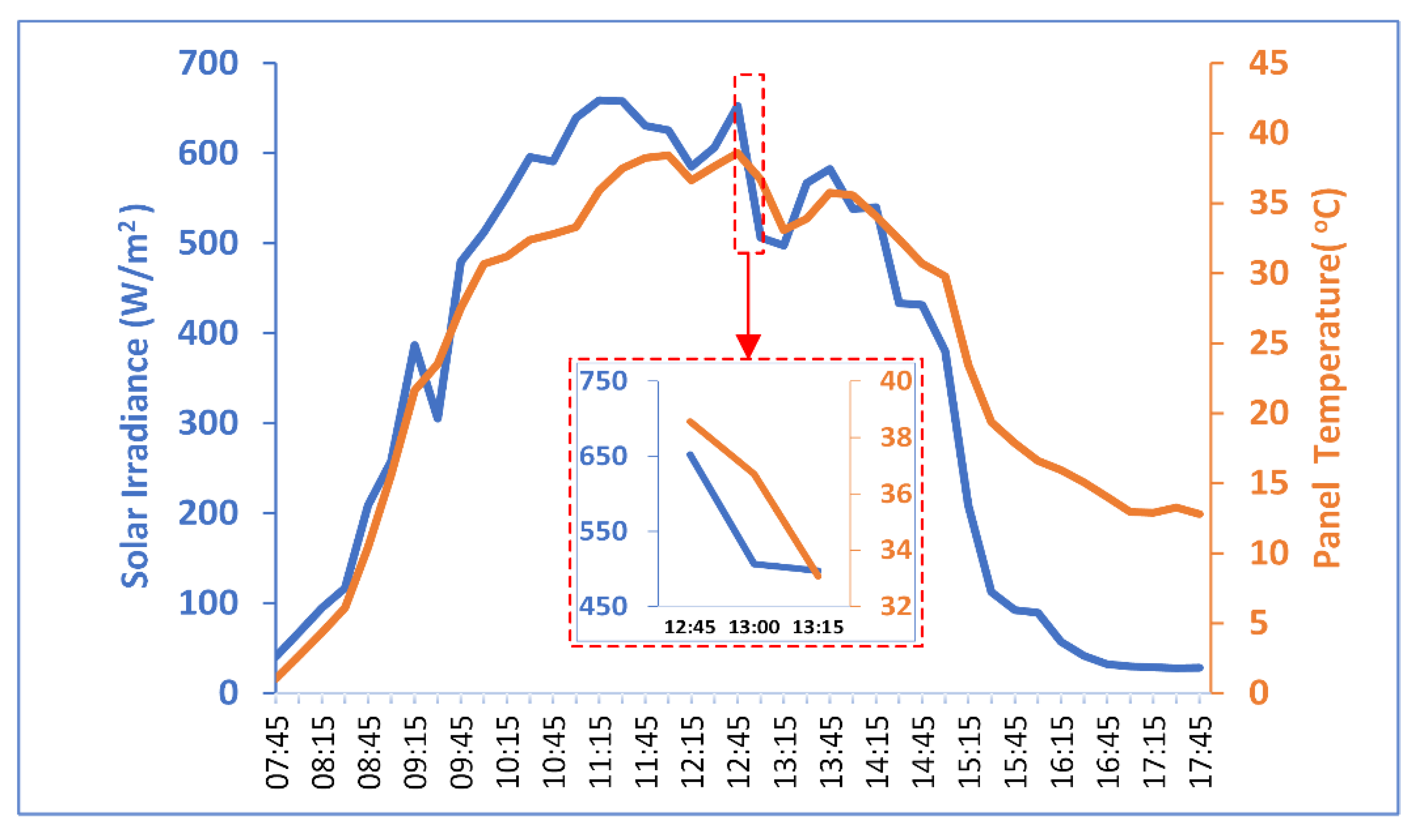
Figure 15.
In this experimental study, the performance of the proposed hybrid control structure was analyzed to obtain maximum power from a PV panel under changes in environmental conditions between 11.45 and 12.15 h. As seen in
Figure 15, the solar irradiance and panel temperature values decreased from 652.33 W/m
2 and 38.57 °C to 497.60 W/m
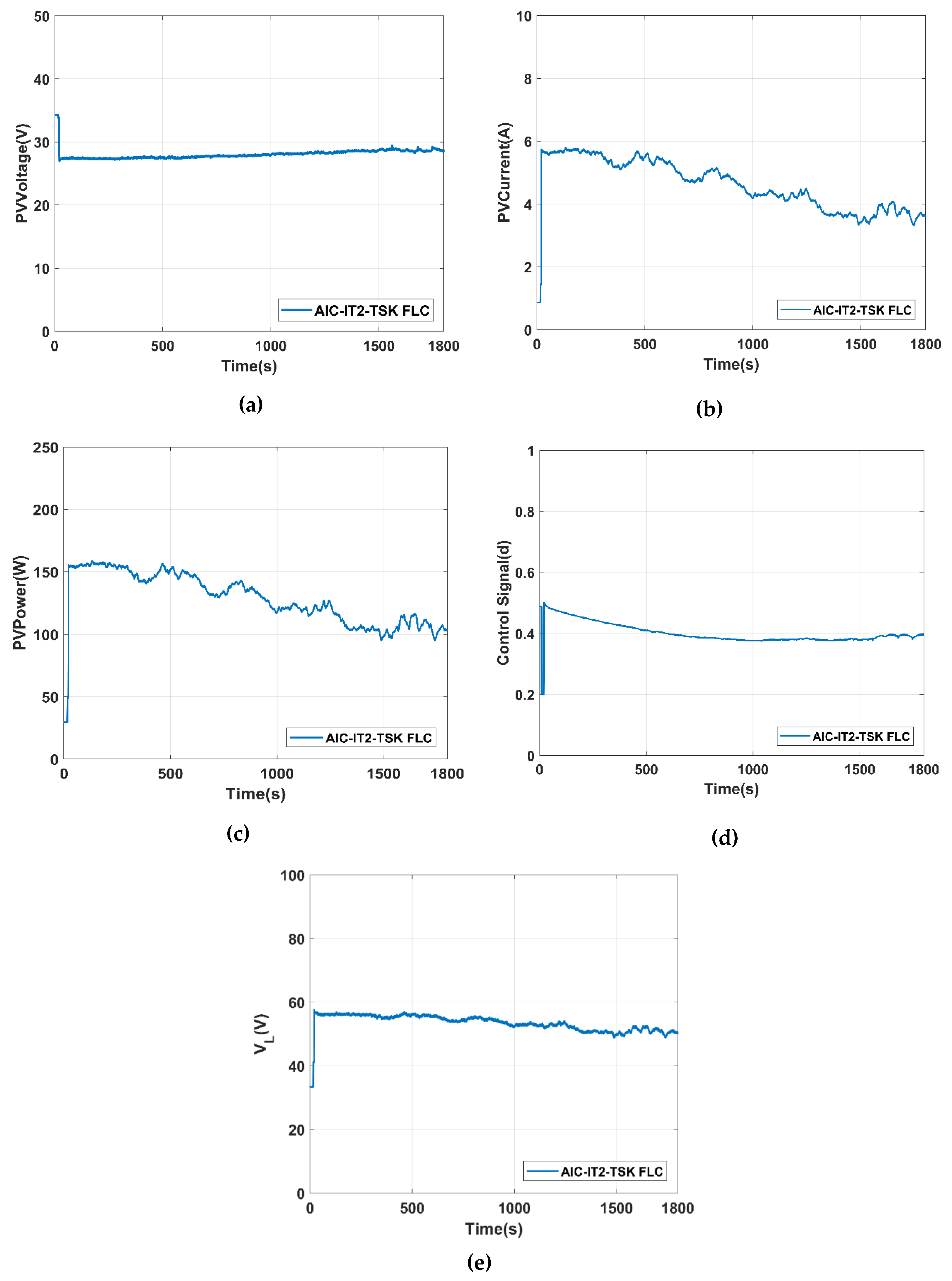
2 and 33.07 °C throughout the experimental operation. The PWM signal was applied to the gate driver circuit after 20.74 s of operation using the ’PWM START/STOP’ block on the RTI model. Experimental results of PV voltage, PV current, PV power, control signal, and DC-DC converter output voltage (V
L) are shown in
Figure 16a–e, respectively. As shown in
Figure 16a, PV voltage value increased from 27.7 V to 28.61 V. Notwithstanding these environmental changes, it can clearly be seen that the proposed hybrid control structure keeps the PV voltage value almost around the MPP value. The PV current value decreased from 5.74 A to 3.61 A simultaneously with decreasing solar irradiance value. As obviously seen in
Figure 16c, the power value obtained from the PV panel decreased from 165.3 W to 103.3 W, and the proposed hybrid control structure successfully decided the proper duty cycle to be applied to the DC-DC converter in order to extract maximum power from the PV panel. As seen in the control signal of the proposed hybrid control structure, despite the changes in environmental conditions, the controller generated a stable control signal for the real-time system. This situation has provided better MPP tracking performance. As seen in
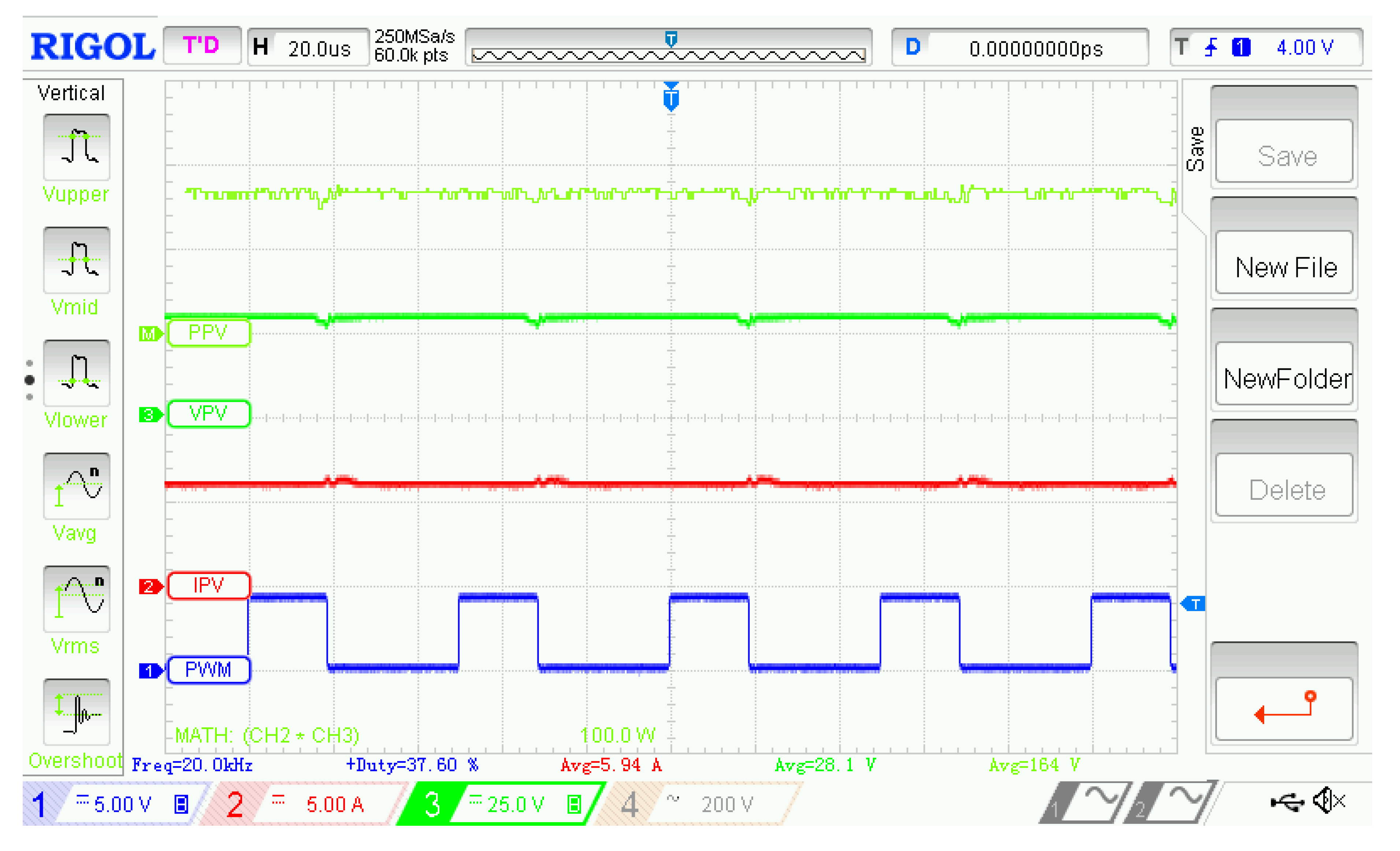
Figure 16e, the DC-DC converter had a stable output voltage which shows the accuracy of converter design. PV power, PV voltage, PV current, and PWM waveforms received from a digital oscilloscope are illustrated in
Figure 17. The results confirm that steady-state operating performance of the AIC-IT2-TSKFLC achieves the maximum output power for the PV system.


