Article

An Approach to Calculating Casing Bearing Capacity with Parabolic Deformation Characteristics Under Local Radial Loading

1
Institute of Unconventional Oil & Gas, Northeast Petroleum University, Daqing 163318, China
2
Key Laboratory of Continental Shale Accumulation and Development, Ministry of Education, Northeast Petroleum University, Daqing 163318, China
3
School of Petroleum Engineering, Northeast Petroleum University, Daqing 163318, China
4
Deep Earth Energy Laboratory, Department of Civil Engineering, Monash University, Building 60, Melbourne, Victoria 3800, Australia
5
School of Electrical Engineering & Information, Northeast Petroleum University, Daqing 163318, China
6
Heilongjiang Provincial Key Laboratory of Networking and Intelligent Control, Daqing 163318, China
*
Author to whom correspondence should be addressed.
Energies 2020, 13(7), 1769; https://doi.org/10.3390/en13071769
Submission received: 21 February 2020 / Revised: 23 March 2020 / Accepted: 2 April 2020 / Published: 7 April 2020

Abstract

:
In the process of waterflooding technology in the Jilin oilfield, local radial compressive stress caused by rock deformation results in local casing collapse. According to statistics regarding casing-deformation characteristics, a certain number of these characteristics are approximately parabola-shaped at the radial-deformation bottom, and the boundary of the whole deformation area is approximately symmetrical and double-parabola-shaped. The main work of this article focused on occurrences of such casing deformation. Assuming that, in the process of casing deformation, external work is totally converted into energy consumption due to the deformation, the variation regularity of bearing capacity under local radial load was obtained. In the Qing-1 stratum of the Jilin oilfield, by selecting casing with radial collapse deformation parameters of 41/2″J55, 51/2″J55, 41/2″N80, and 51/2″N80, radial bearing capacity was calculated. Study results showed that the casing bearing-capacity value was reduced by 39.69% compared with the current API 5C3 standard when under the action of a local radial load. The casing collapsed due to the impact of local radial loads produced by mudstone creep. A series of relationships between radial bearing strength and casing parameters were also obtained. The research results are of significant academic value for the compilation of casing design codes or standards under local radial loading.

Graphical Abstract

1. Introduction

After a period of waterflood development in oil fields, a variety of casing damage will occur, such as squashing, diameter reduction and staggered sections. However, in some oilfields, such as Daqing, Jilin, Xinjiang, Belridge, Lost Hills, and Samotlor, casing collapse caused by water injection accounts for about 70% of the all casing collapses [1,2,3,4,5,6,7]. The causes of casing damage are very complicated, but the root cause is that the external load on the casing under the action of crustal stress exceeds the external load strength of the casing. Due to water-flooding penetration into the mudstone layer, rock-caused creep under the action of overlying strata leads to the occurrence of local radial casing deformation. Therefore, casing strength design is an opportunity for researchers to prevent casing failure. In the 1940s, scholars of the Soviet Union ГИНИ (Булгакoв, 1930) and Г.М.Саркисo developed a casing strength design; then, in the early 1980s, ищенкo established the mechanical model of the casing wall under heterogeneous load. By means of stress superposition, the theoretical formula of stress change in casing was obtained [8]. Since then, the strength-design standard represented by the American Petroleum Association (API) has been widely used in many countries. At present, the API 5C3 and ISO 10400 standards [9,10] are used as the design standards of casing strength in the petroleum industry, but most of those standards are based on calculated results under uniform and non-uniform loads [11,12,13,14,15,16]. By using the lead-mold method to determine the casing-deformation characteristics of the Jilin oilfield, it was found that the casing deformation was due to local radial deformation, as shown in Figure 1 [17]. Previous studies [18,19] have found that casing deformation is mainly manifested as axial extrusion deformation and shear deformation. Axial compression failure occurs at the production stage, while axial shear failure occurs at the edge of the collapse area. Many scholars [20,21,22,23,24,25,26,27] have found that the main reason for local radial casing deformation is the lateral extrusion formed by water-absorption mudstone expansion. The finite element analysis is applied to establish the shape of casing deformation characteristics. Results showed that the bottom and side boundaries of the casing deformation were approximately parabola-shaped (Figure 2).
Based on the principle of conservation of work and energy, the casing types 41/2″J55, 51/2″J55, 41/2″N80, and 51/2″N80 in the Jilin oilfield were selected as examples. The mechanical model of the bearing capacity of the casing under local radial load was established, and the relationship between the radial bearing capacity of the casing and local radial load was obtained. In order to verify the casing deformation, finite element simulation was carried out. The numerical simulation results were good. The calculation results show that the casing radial bearing capacity was decreased under local radial load, and the relationship between casing radial bearing capacity and casing wall thickness, yield strength, and other parameters were obtained. This paper is an effective supplement to the API 5C3 and ISO 10400 standards, providing a scientific basis for casing and parameter design optimization of future water-flooding reservoirs. It is of great significance to reduce casing-collapse rates and reduce the cost of oilfield maintenance.

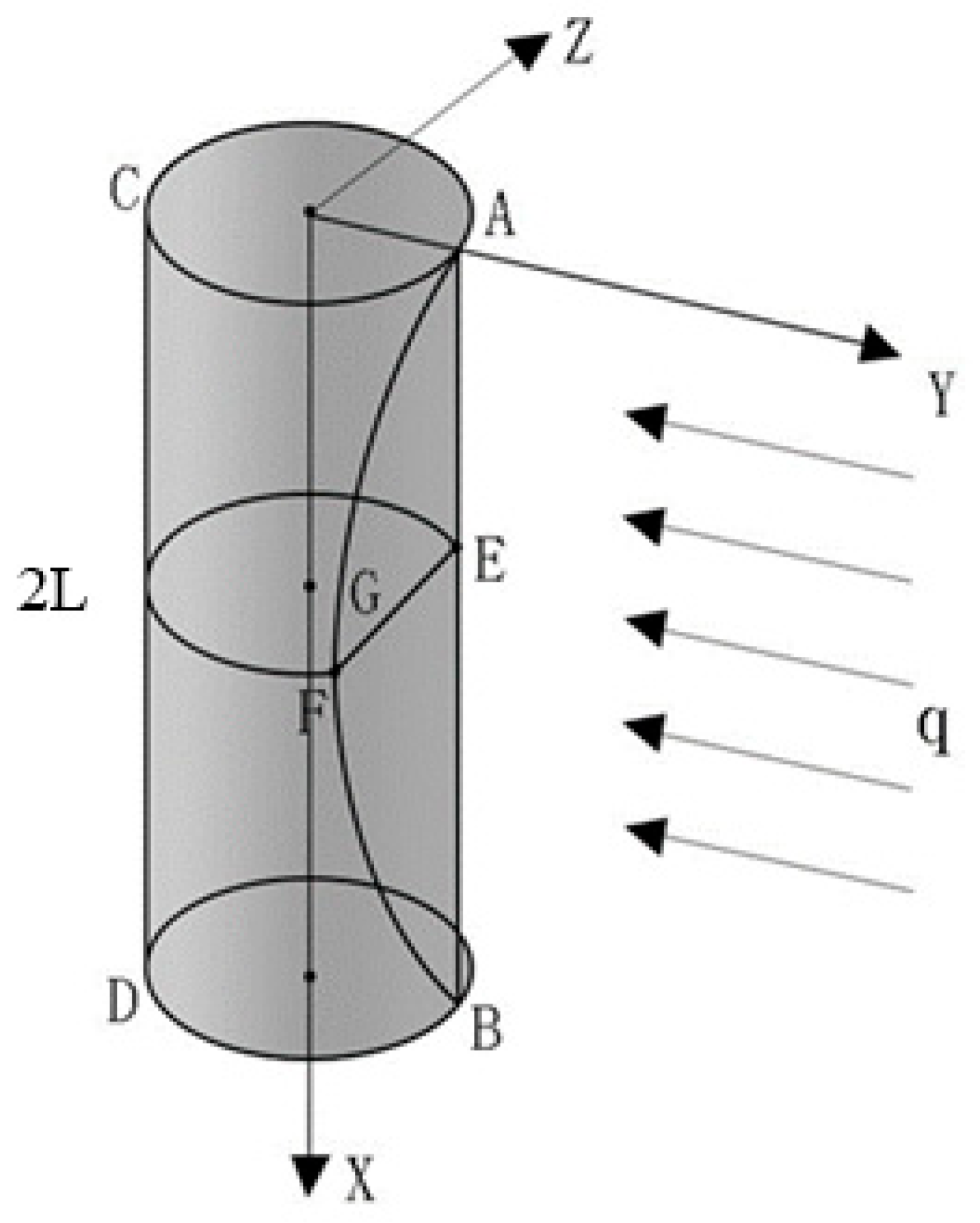
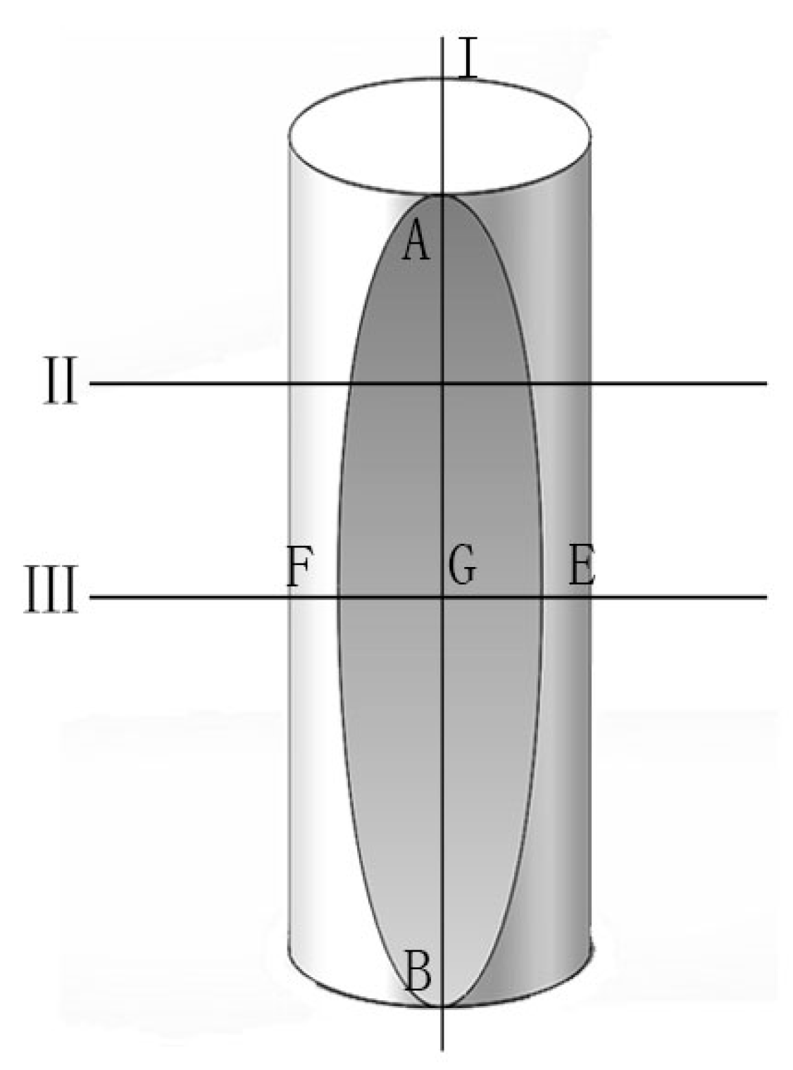
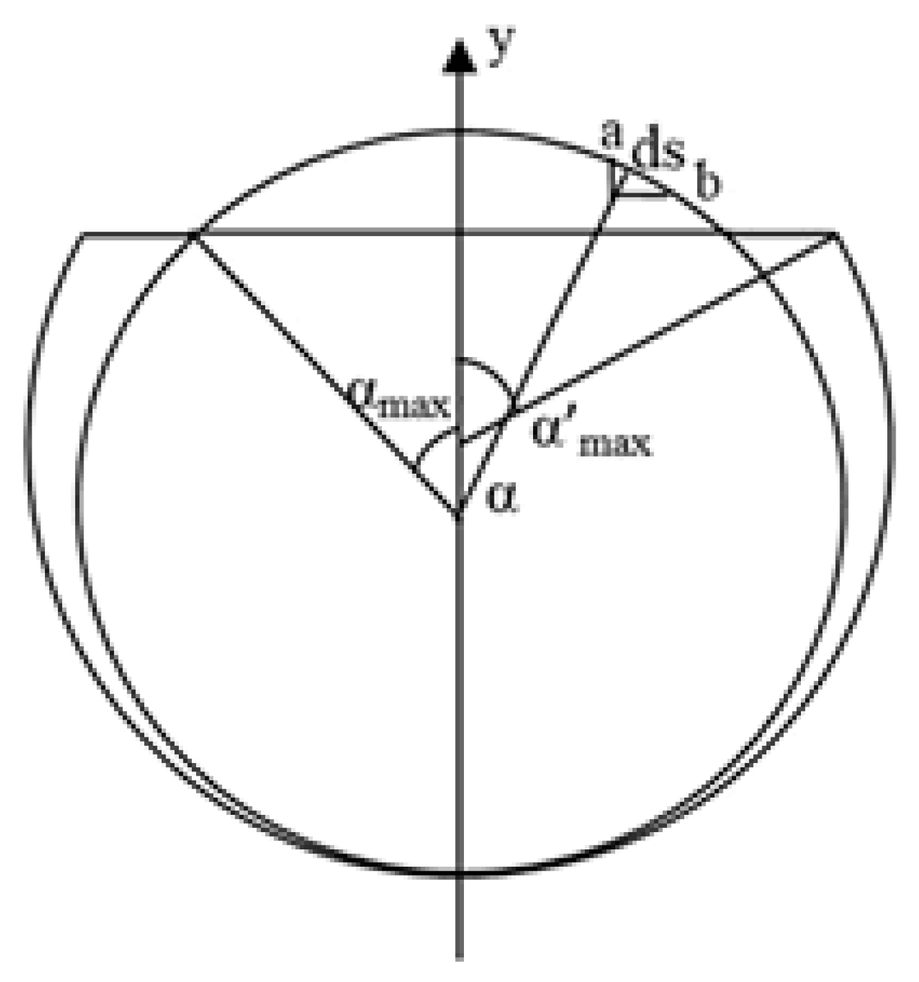
2. Establishment of the Mechanical Casing Model

Through the analysis of casing collapse area and form, it is found that local radial load is the main factor leading to casing deformation. Assuming that under the action of lateral uniform load, the plastic deformation area of casing has two symmetrical parabolic shapes, a simplified casing for a clamped–clamped thin-walled metal circular tube is the ideal rigid-plastic model, and the incompressible material at the dent depth of the circular tube along the x-axis continuously varies in the deformation zone. The local radial load experienced plastic deformation, as shown in Figure 3 and Figure 4; the −y is the direction of plastic-deformation projection. Assuming that the deflection of the circular tube and the corner of the circular tube were zero, the cross-section curve part became arc-shaped after plastic deformation occurred. There was a homolographic axis through the center of the then non-deformable circular cross-section after plastic deformation occurred.
This study regarded wellbore deration as the coordinate axis and established a Cartesian coordinate system, assuming that the radius of the metal circular tube was R , and the plastic-deformation length of the casing collapse was 2 L . Through the geometric relation, the coordinates of each point at the deformation boundary could be expressed as shown in Figure 3.
{ A ( 0 , R , 0 ) B ( 2 L , R , 0 ) E ( L , R δ max , l E F 2 ) F ( L , R δ max , l E F 2 ) G ( L , R δ max , 0 )
According to the correspondence relationship of the section in the II-II direction (Figure 5), it could be obtained between the parameters in the figure:
α 0 = arccos ( R δ max R )
R = π R sin ( α 0 ) + ( π α 0 )
R sin ( α 0 ) = R α 0
R [ cos ( α 0 ) + 1 ] = 2 R δ max
tan α 0 = R α 0 2 R R δ max
Assuming that the deformed surface of the lateral deformation of the casing is parabolic, the curve equation for establishing the deformation boundary is:
y ( x ) = δ max L 2 x 2 2 δ max L x + R
z ( x ) = R α 0 L 2 x 2 + 2 R α 0 L x

3. Calculation of Work and Energy for the Radial Load Deformation

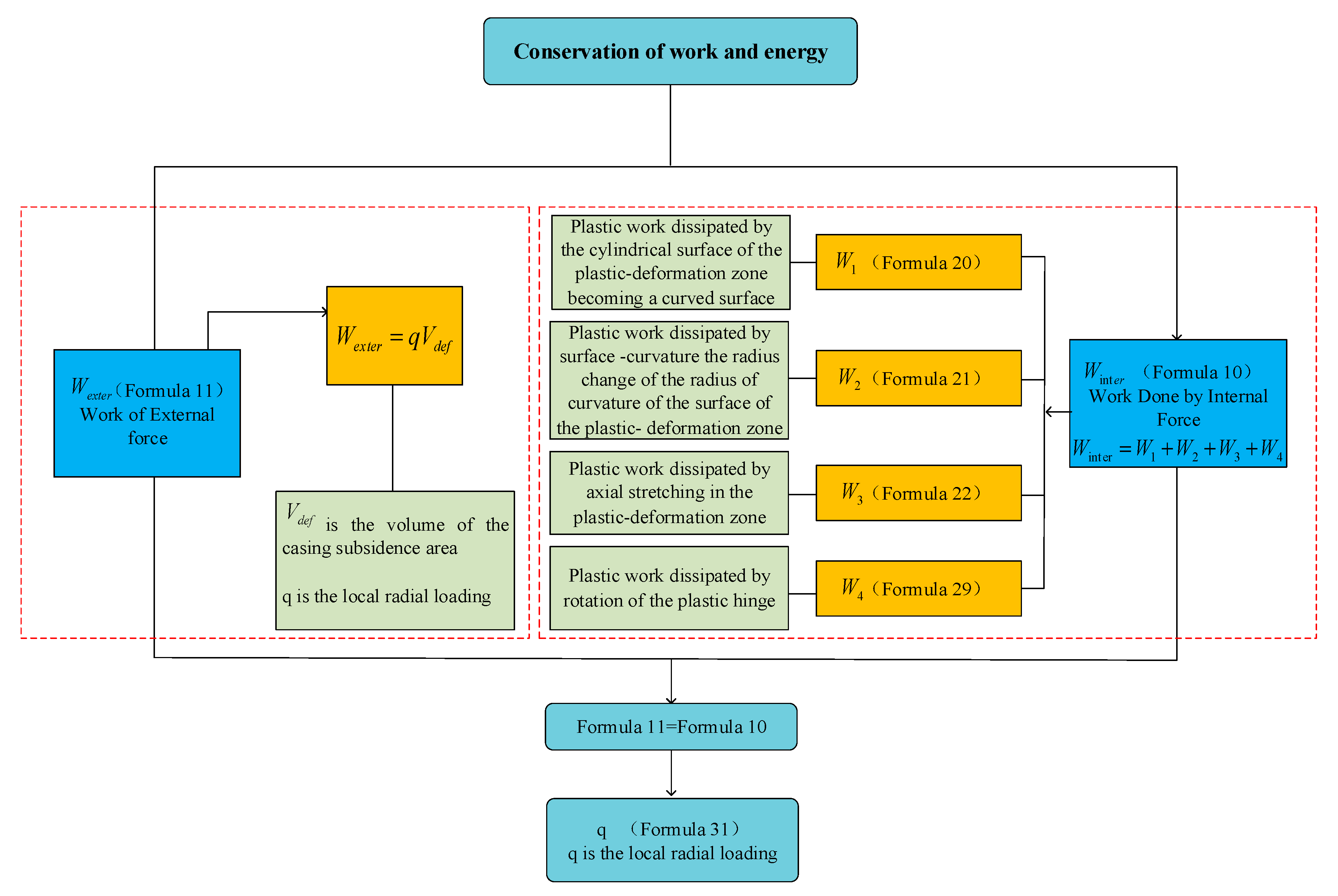
3.1. Conservation of Work and Energy

According to the principle of conservation of work and energy, when the rock absorbs water and creeps, the external forces acting on the casing in the form of local radial loads are all converted into internal dissipated energy of various local deformations of the casing.
According to the conservation of work and energy balance plastic deformation of the casing, the following equation can be obtained:
W e x t e r = W i n t e r
where W e x t e r is the work that the local radial load works on the casing.
When the rock absorbs water and creeps, the external force acting on the casing in the form of local radial load does work. W i n t e r is the total dissipated energy of local radial deformation of casing, mainly includes the following aspects:
(1)
W 1 : Plastic work dissipated by the cylindrical surface of the plastic-deformation zone becoming a curved surface.
(2)
W 2 : Plastic work dissipated by surface curvature radius change of the plastic-deformation zone.
(3)
W 3 : Plastic work dissipated by axial stretching in the plastic-deformation zone.
(4)
W 4 : Plastic work dissipated by rotation of the plastic hinge.
That is:
W i n t e r = W 1 + W 2 + W 3 + W 4
where, W i n t e r is the sum of internal dissipative work.
According to the relation of Equation (9), the calculation flow in this paper is shown in Figure 6.

3.2. Work of External Load and Work of Internal Load in Local Radial Load

3.2.1. Work of External Load W e x t e r

When the casing is under uniform radial local load, the work done to the casing by the local load is:
W e x t e r = q V d e f ,
where V d e f is the volume of the casing subsidence area; V d e f can be expressed as shown in Figure 3, and:
V d e f = 2 0 L [ ( R 2 α max · R · sin α max · R · cos α max ) ] d x = 4 3 R 2 L α 0 + R 2 L π 2 α 0 ( cos 2 α Fresenl S ( 2 α 0 π ) FresenlC ( 2 α 0 π ) sin 2 α 0 )
The Fresnel integral can be obtained by the two following series:
S ( x ) = 0 x sin ( t 2 ) d t = n = 0 ( 1 ) n x 4 n + 3 ( 2 n + 1 ) ! ( 4 n + 3 )
C ( x ) = 0 x cos ( t 2 ) d t = n = 0 ( 1 ) n x 4 n + 1 ( 2 n ) ! ( 4 n + 1 )

3.2.2. Work of Internal Load
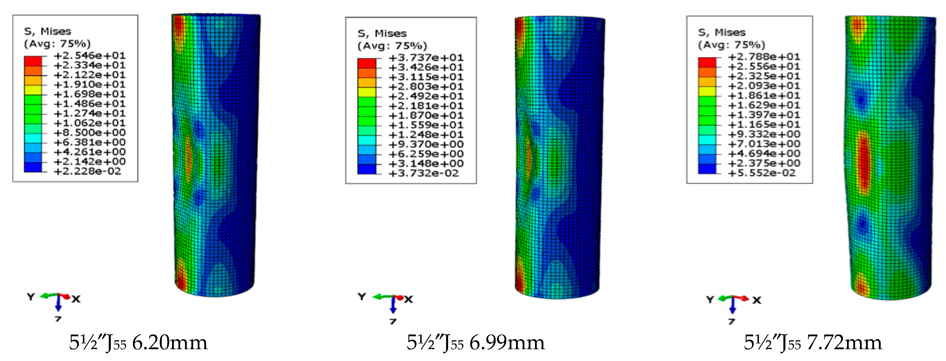
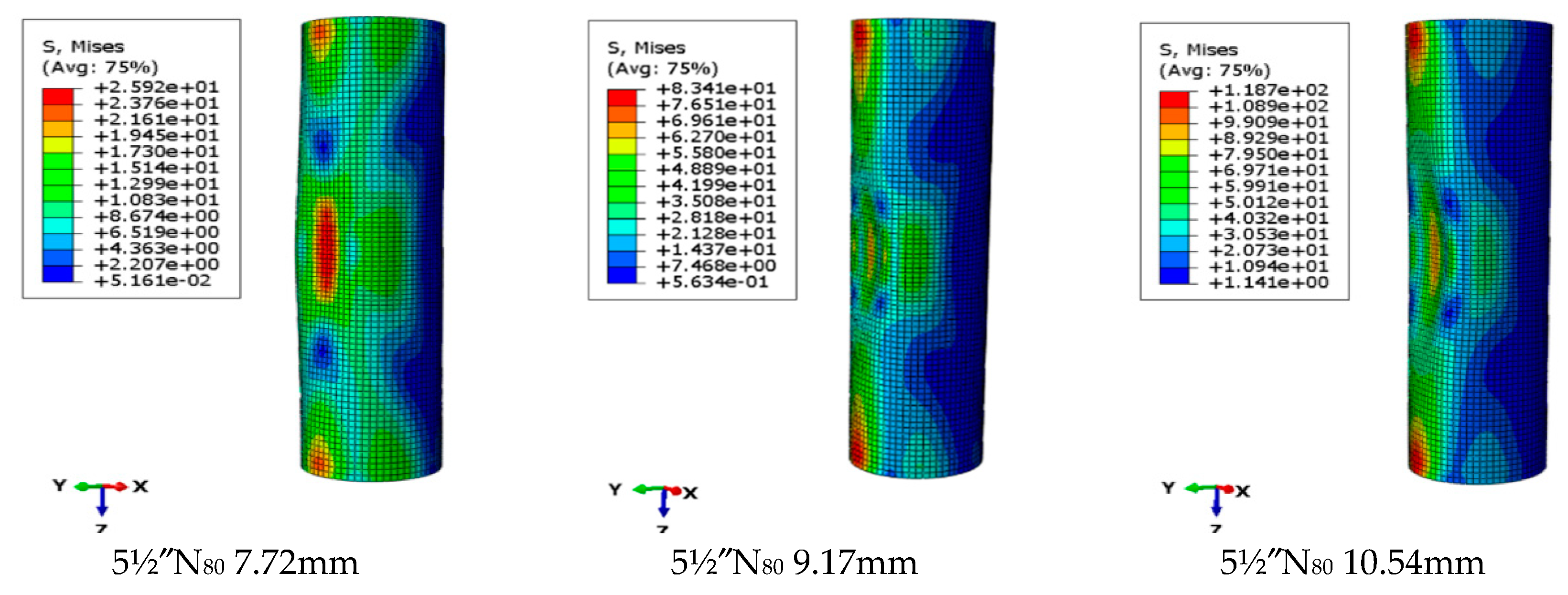
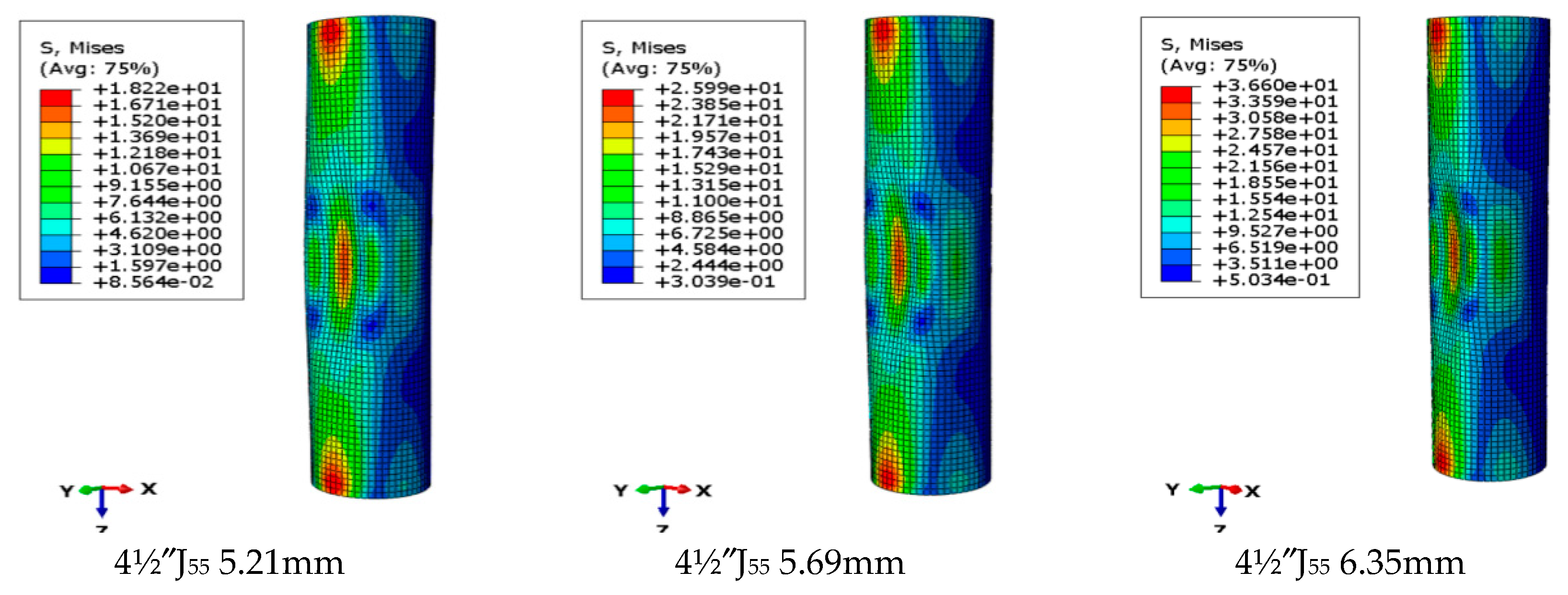
 W i n t e r

(1) Dissipation energy on the plastic-deformation area when the cylinder is converted to the camber.
The dissipation energy of d s , as shown in Figure 7, is:
d W s = 1 2 σ 0 t 2 α d s ,
where t is the casing wall thickness and σ 0 is the casing yield stress.
The dissipation energy of deformation length E F , as shown in Figure 5, is:
W s = 2 0 s 1 2 σ 0 t 2 α d s = 0 α max σ 0 t 2 R α d α = 1 2 σ 0 t 2 R α max 2
According to Figure 2 and Equation (7), dent depth δ is:
δ = R y ( x ) = 2 δ max L x δ max L 2 x 2
According to the deformation relation, as shown in Figure 6, the deformation relation of z(x) and a(x) is:
z ( x ) = R α max ( x )
Since the dent depth continuously varies along the x axis, α max ( x ) can be described as:
α max ( x ) = z ( x ) R = 2 R α 0 R L x R α 0 R L 2 x 2 = ( 2 x L x 2 L 2 ) α 0
Therefore, dissipated energy in the whole cambered deformation zone is shown as:
W 1 = 2 0 L W s d x = 8 15 σ 0 t 2 R L α 0 2 .
(2) Plastic dissipative work W2 is produced by the surface of the plastic zone when the radius of curvature changes by a derivation process similar to W1, which can obtain the surface curvature radial variation of plastic dissipative energy W 2 . Dissipation work W 2 is shown as:
W 2 = 2 0 h 2 σ 0 D 2 4 · r · ( π α ( x ) ) ( α ( x ) α ( x ) ) d x = 32 15 N 0 R L ( π α 0 ) ( α 0 α 0 ) ,
where α ( x ) is the angle between the line from the boundary of any section to the center and the concave direction when the surface curvature radius changes, as shown in Figure 6.
(3) Dissipation of the plastic work where the plastic hinge line rotation is:
W 3 E A = 0 E A N 0 ( 2 x L x 2 L 2 ) α 0 d x = N 0 α 0 L 2 ( L · E A 2 E A 3 3 )
where the length of space curve E A is:
E A = 0 L 1 + ( d y ( x ) d x ) 2 + ( d z ( x ) d x ) 2 d x
By substituting Equations (7) and (8) into Equation (23), the E A can be derived:
E A = 4 ( δ max 2 + R 2 α 0 2 ) + L 2 + L 2 4 δ max 2 + R 2 α 0 2 ln 4 ( δ max 2 + R 2 α 0 2 ) + L 2 + 2 δ max 2 + R 2 α 0 2 L
In the same way, the plastic dissipative work can be obtained when yield lines A F , F B , and B E rotate, and Equation (25) can be obtained on the basis of mirror symmetry:
W 3 E A = W 3 A F = W 3 F B = W 3 B E
Consequently, the total dissipative work when the plastic hinge lines rotate is as follows:
W 3 = W 3 E A + W 3 A F + W 3 F B + W 3 B E = 4 W 3 E A
(4) Dissipation of plastic work W 4 on plastic deformation area when under axial tension.
On the basis of the geometric relationship in Figure 8, maximum axial elongation is known:
Δ ε = 2 ( G A L ) .
The length of the curve is:
G A = 0 L 1 + ( d y d x ) 2 d x = 2 δ L L 4 4 δ max 2 + L 2 + L 2 4 δ max ln L 2 + 4 δ max 2 + 2 δ max 4 δ max 2 + L 2 L 2
On the basis of the deformation mechanism, to solve the volume of the deformation zone, the dissipation work of axial tension is:
W 4 = 0 Δ ε M 0 d ε = 2 M 0 ( G A L ) ,
where M 0 is the ultimate bending moment that can be expressed under local radial uniform load in the plastic-deformation zone as follows [28]:
M 0 = σ 0 · D
The calculation relationship between the lateral load of the external load and the deformation parameters of the casing is:
q = 32 15 M 0 L α 0 2 + 32 15 M 0 R L π α 0 α 0 α 0 + 2 N 0 ( G A L ) + 4 M 0 α 0 L 2 ( L · E A 2 E A 3 3 ) [ 4 3 R 2 L α 0 + R 2 L π 2 α 0 ( cos 2 α 0 Fresenl S ( 2 α 0 π ) FresenlC ( 2 α 0 π ) sin 2 α 0 ) ]

4. Example Analysis

In this paper, wells with casing collapse in the Qingshankou formation of the Jilin oilfield were selected as examples. The casing types in the mudstone interval were mainly 4½J55 (114.3 mm), 5½″J55 (139.7 mm), 41/2″N80 (114.3 mm), and 5½″N80 (139.7 mm). We took a plastic deformation length of 2 m, selected casings with different wall thicknesses for calculation, obtained the radial bearing capacity value of the radial casing, and simulated the actual bearing capacity value of the casing under different deformation conditions by the finite element method. The corresponding parameters and calculation results are shown in Table 1 and Figure 8, Figure 9, Figure 10, Figure 11, Figure 12, Figure 13, Figure 14 and Figure 15.
As shown in Figure 8, Figure 9, Figure 10, Figure 11, Figure 12, Figure 13, Figure 14 and Figure 15, when the casing is deformed, its bearing capacity is obviously lower than the anti-extrusion strength designed in the API standard. In order to verify the casing deformation, finite element simulation was carried out. The deformation of four types of casing under local radial load based on finite element simulation was consistent with the analysis results based on the principle of conservation of work and energy.
In this paper, four types of casing in the Qing-1 section of Jilin oilfield’s water-absorbing layers were selected as research examples. Through the theoretical calculation model and the numerical simulation method, the influence of radial stress, induced by water absorption and mudstone expansion in a local state, on casing strength was calculated and analyzed. Results show that when the casing was subjected to a local radial load induced by the suction of the mudstone layer, the bearing-capacity value of the casing in the local area of the extrusion deformation was smaller than the current American Petroleum Institute (API) casing strength design standard value, considering overall load. Results in Figure 16, Figure 17, Figure 18, Figure 19, Figure 20 and Figure 21 summarize the relationship between relative and absolute decreases of casing bearing capacity and casing wall thickness, casing yield strength, and maximum casing deformation, respectively. In comparison, the greater the casing wall thickness and yield stress are, the smaller the casing bearing-capacity value is compared with the API standard. On the other hand, the larger the maximum casing deformation is, the larger the bearing-capacity value and the API standard value are; the relationship between them can be described by a linear relation. Therefore, in the layer segment with local-deformation characteristics, in the selection of casing string, a casing type with higher extrusion strength should be selected rather than the casing under overall load. This can help avoid casing damage due to local radial load.
We calculated and analyzed the relationship between the bearing capacity of four casing types used in the Qing-1 formation of the Jilin oilfield, casing wall thickness, and yield strength. The results of the four calculation types show that the relationship between casing bearing capacity, wall thickness, and yield stress could be expressed by the linear function of positive correlation under the local radial load of local sections. When the casing is deformed, the thicker the casing wall, the greater the local radial load, the greater the yield stress and the greater the local radial load. For each type of variation relation, refer to the fitting relation in the Figure 22 and Figure 23. Results provide a reference for the selection of other casing types and yield strength of casing wall thickness under this condition.

5. Conclusions

(1)
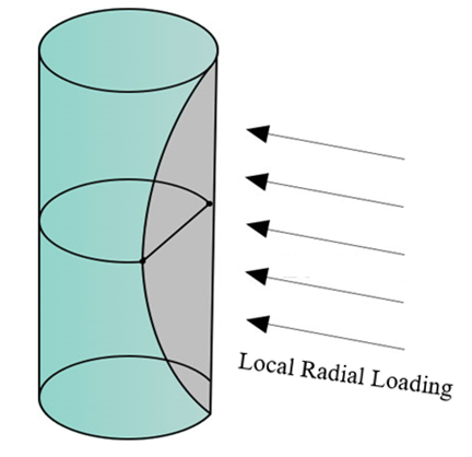
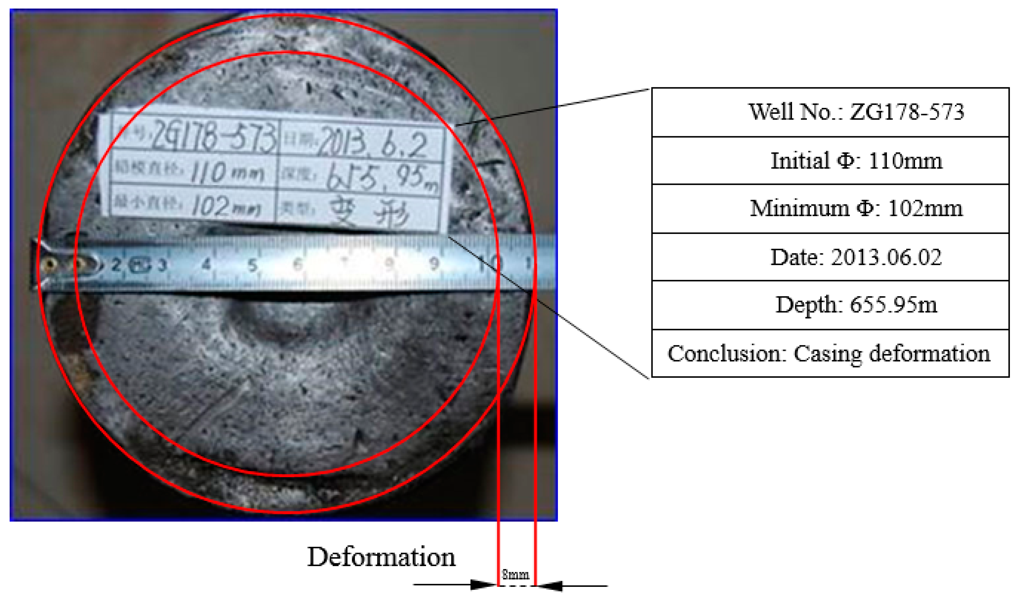
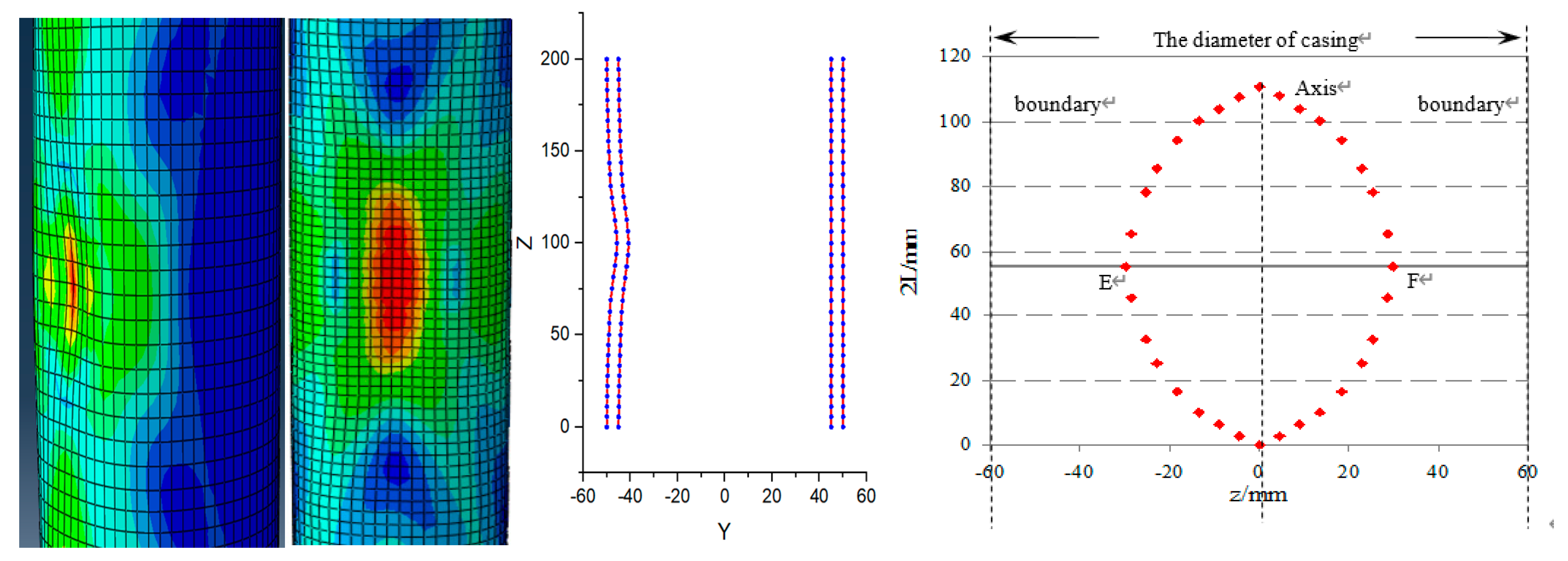
In the process of oilfield water-flooding development, mudstone creeps to form local radial induced stress acting on the casing, resulting in casing-collapse deformation. Through the measurement of casing deformation in some wells in the Jilin oilfield, it was found that the bottom of the radial deformation is parabolic, and the lateral deformation boundary is symmetric parabolic. In this paper, a calculation method for the local radial load collapse deformation of the casing is presented based on the conservation of work and energy.
(2)
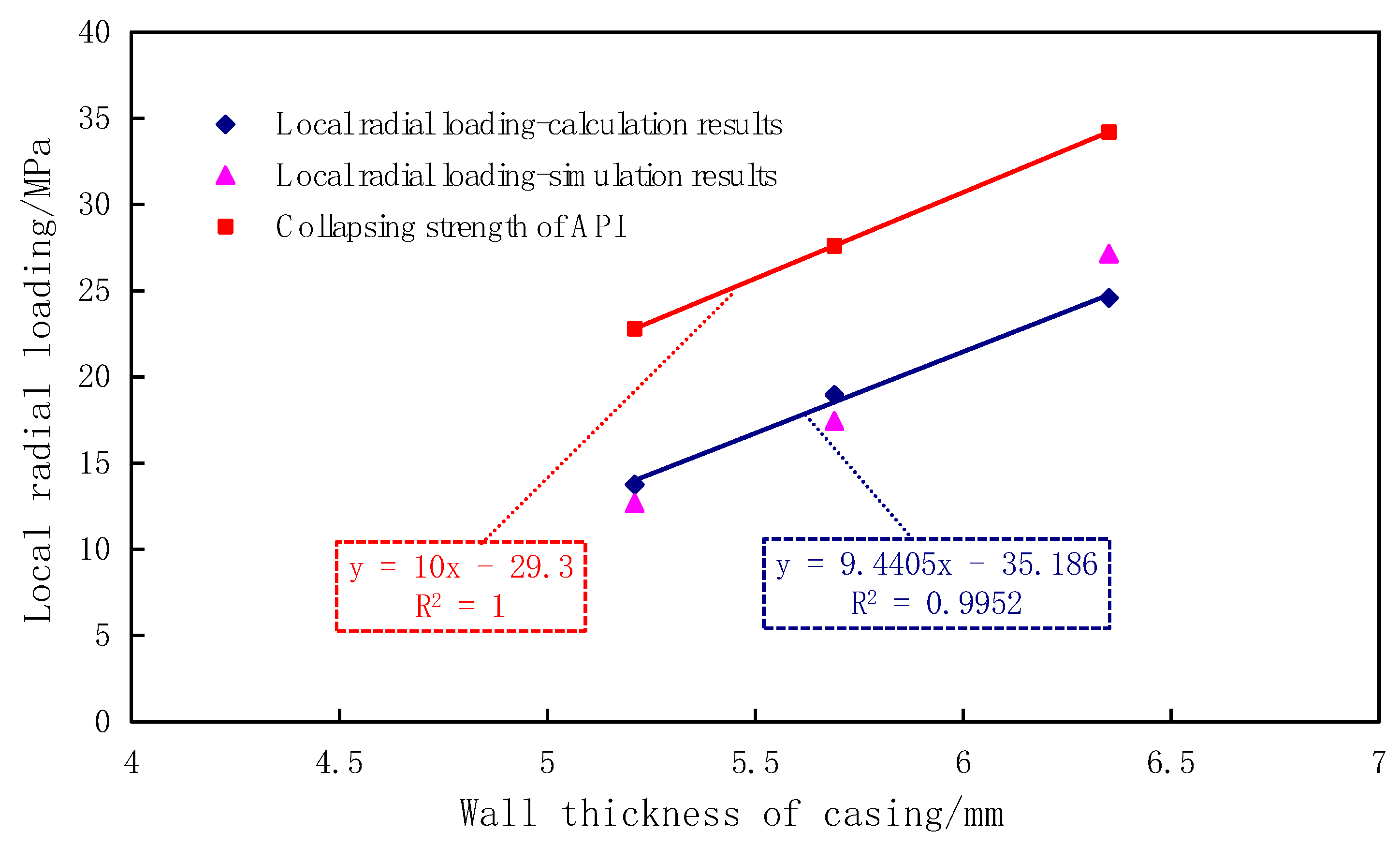
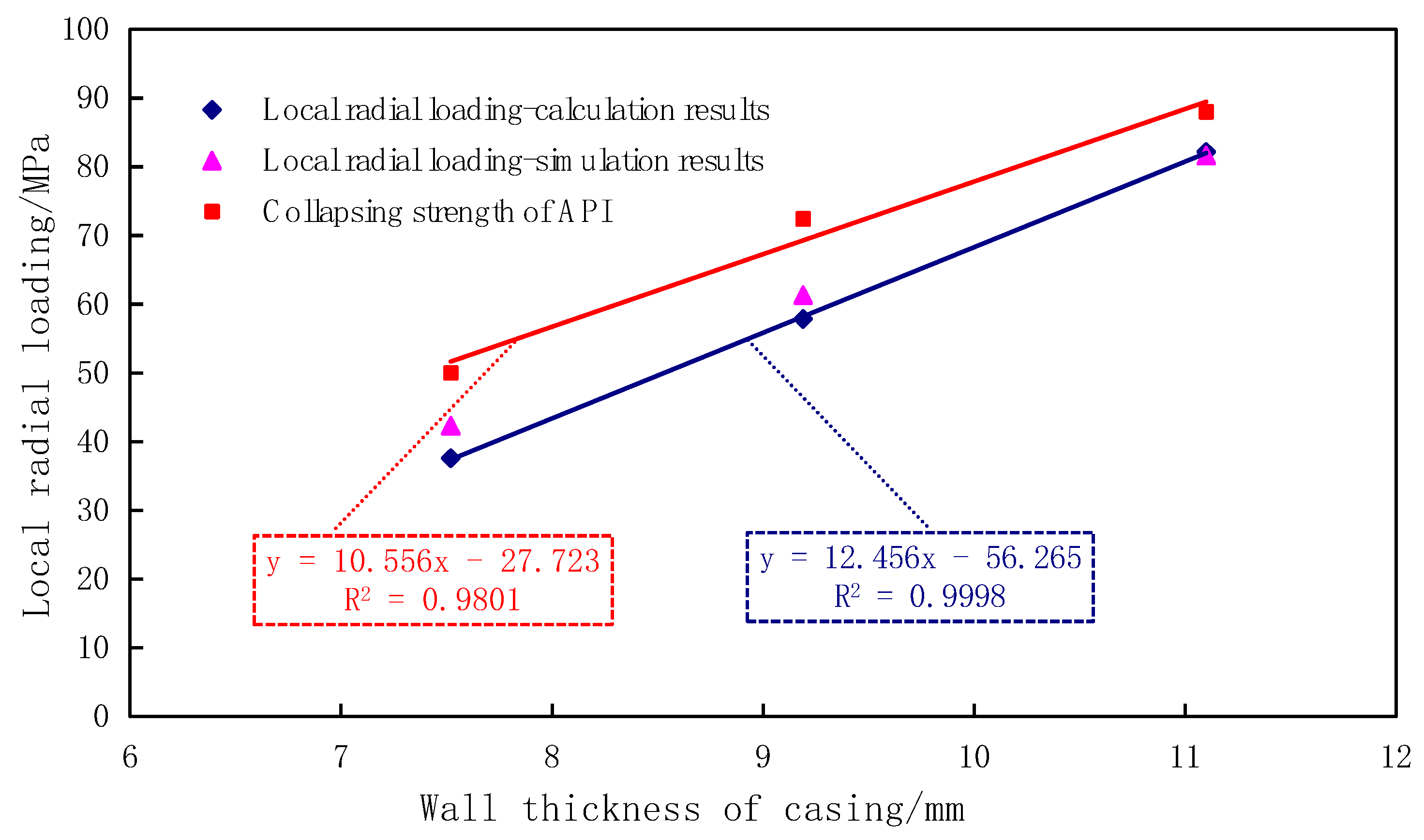
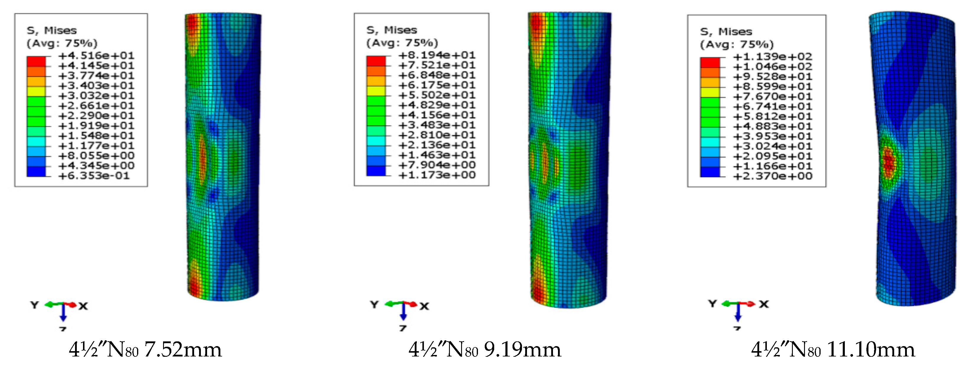
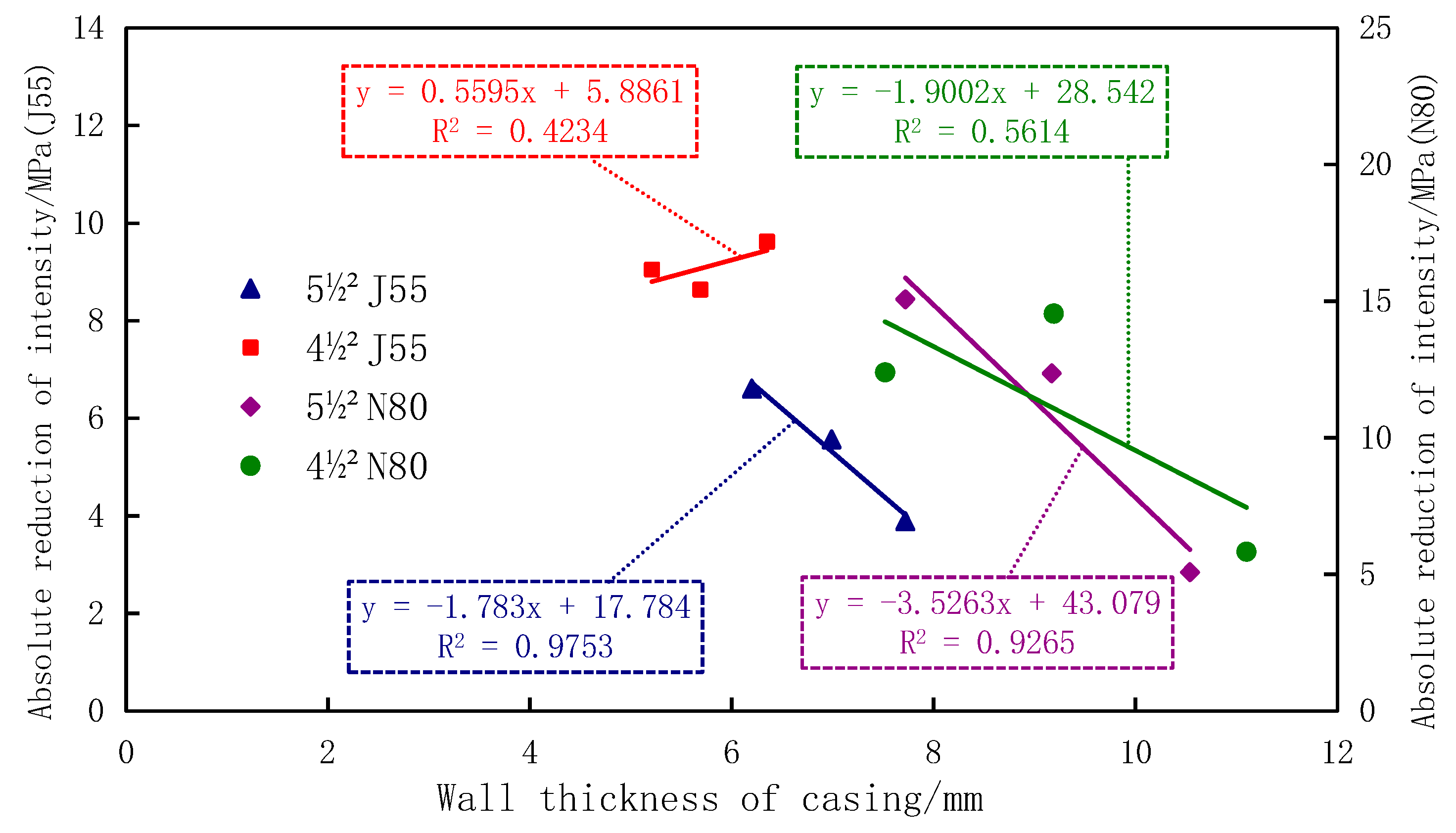
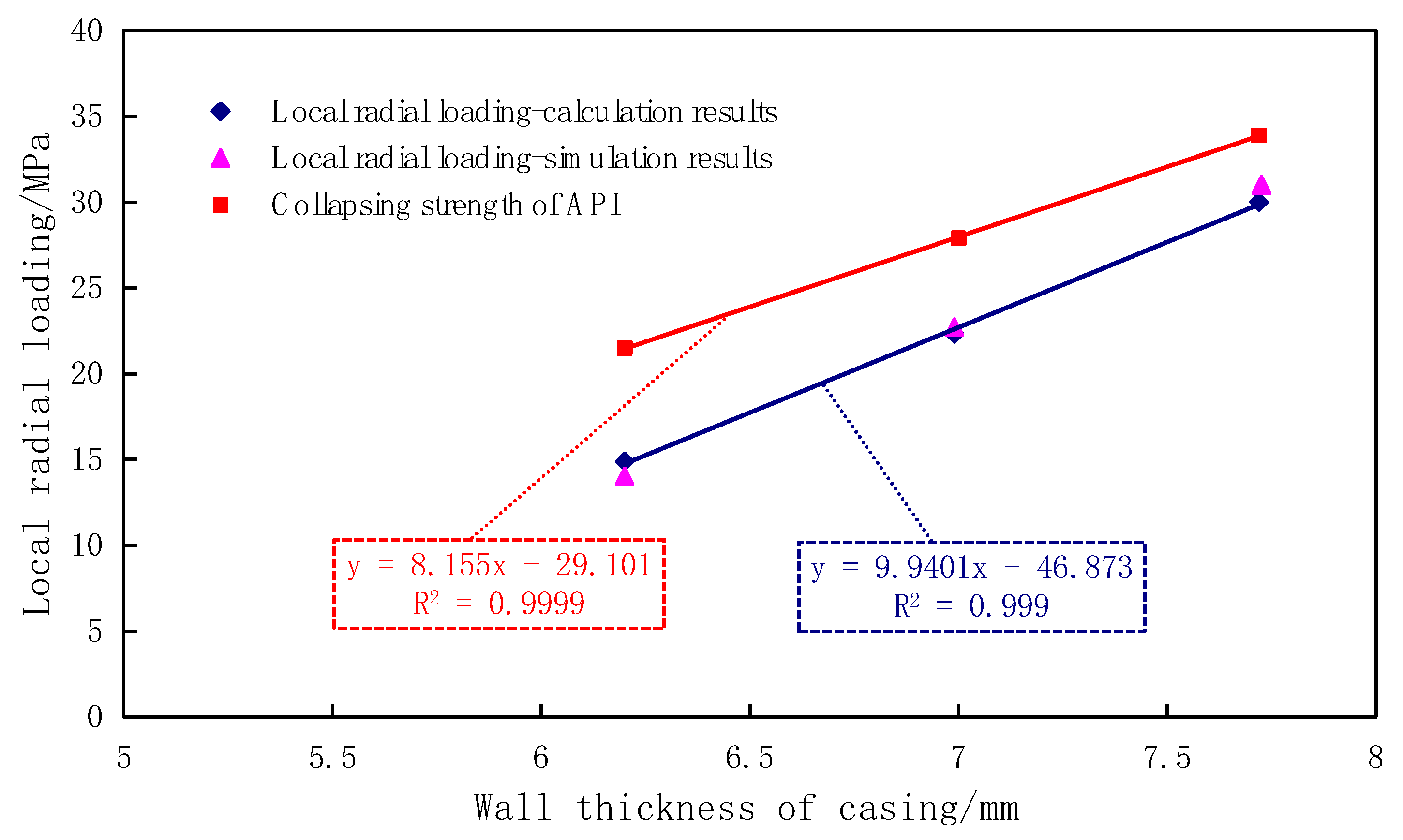
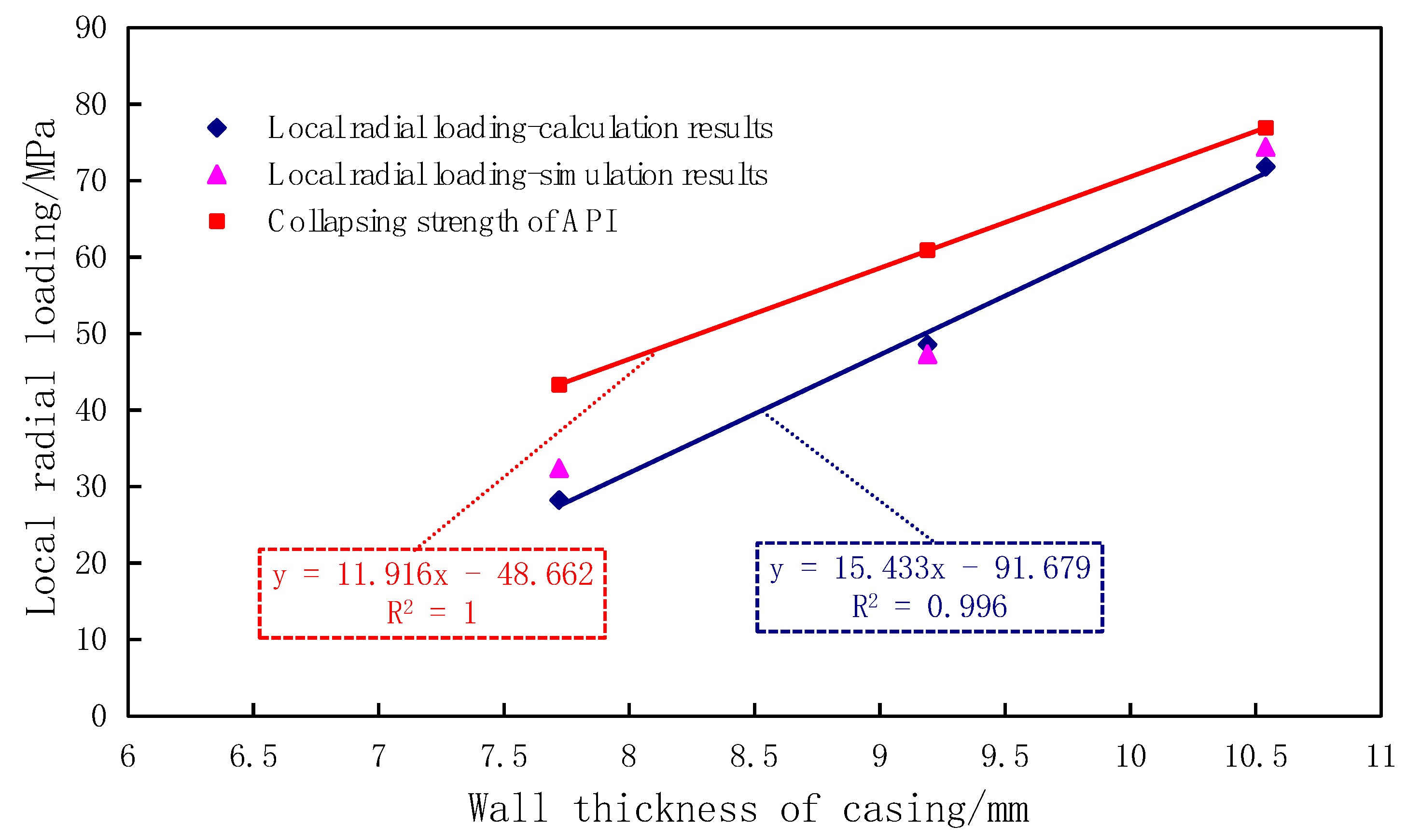
The external work of casing deformation caused by a local radial load was transformed into the dissipation energy of casing deformation. According to the conservation of work and energy, the relationship between bearing capacity and casing deformation was established, and four types of casing wells in the study area were selected for calculation and analysis. The results showed that casing bearing capacity under a local radial load was smaller than the standard value designed by the API industry. Compared with the four casing types, the maximum bearing capacity was reduced by 15.07 MPa, and maximum relative reduction was 39.69%.
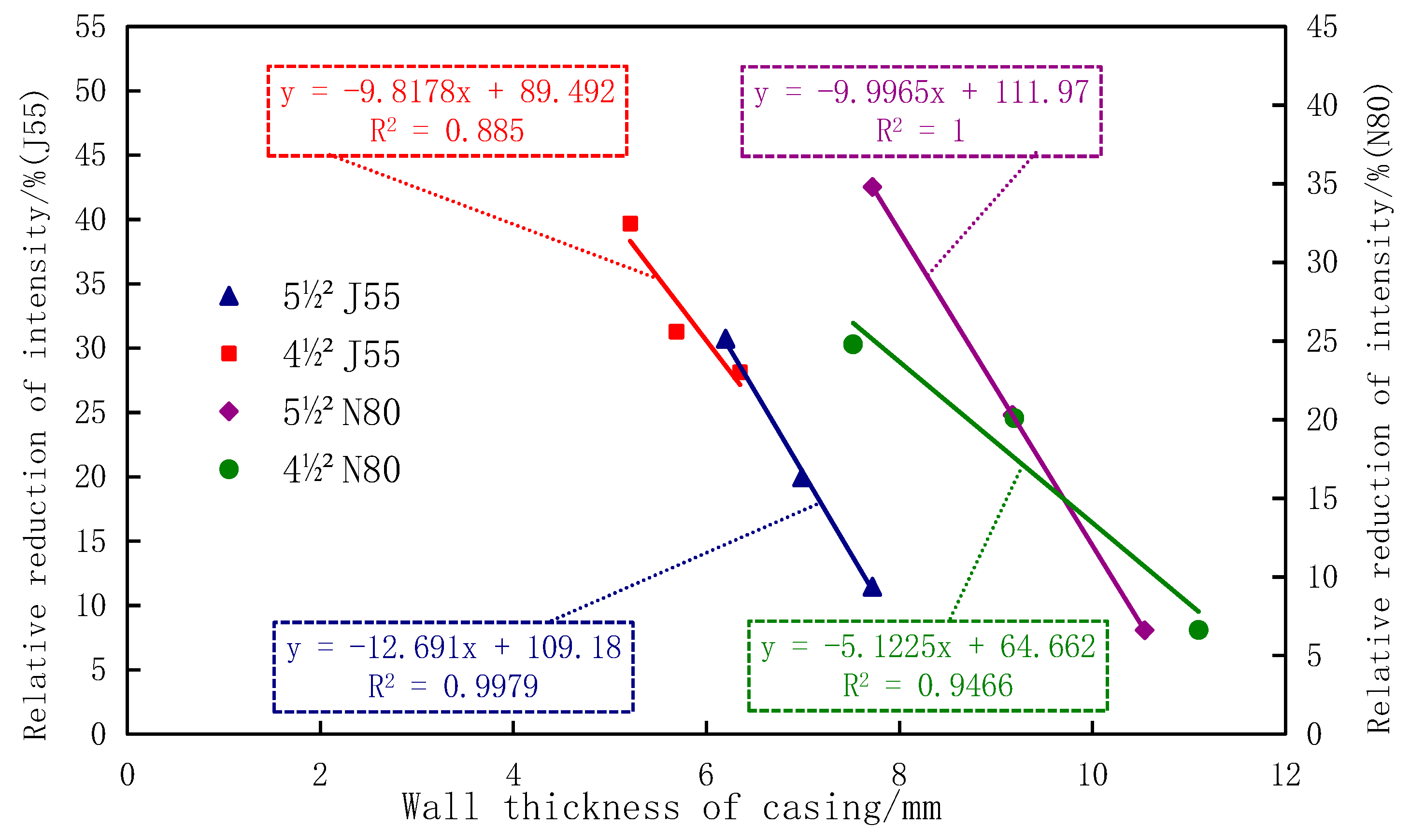
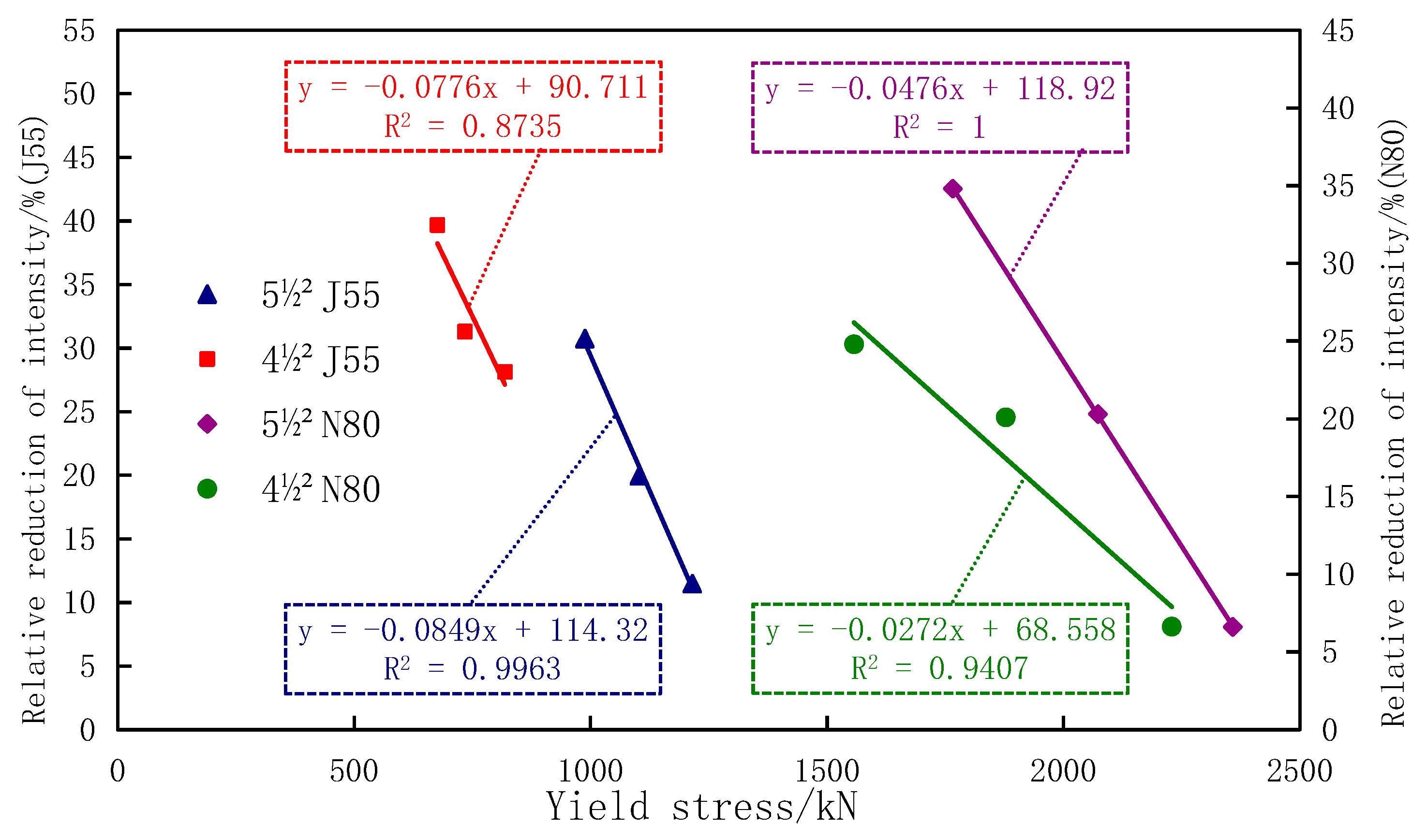
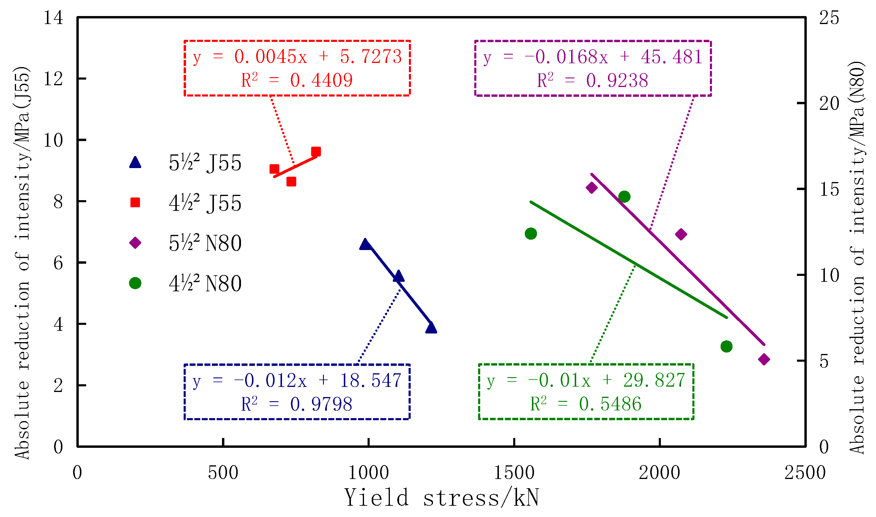
(3)
The results of the four calculation types show that the relationship between casing bearing capacity, wall thickness, and yield stress could be expressed by the linear function of correlation under the local radial load of local sections. Results provide a reference for the selection of other casing types and yield strength of casing wall thickness under this condition.
(4)
The research results showed that, under the action of local radial loading, casing selection according to the current API design standard value cannot meet the requirements of actual projects. A new approach is proposed for casing strength design under local radial loading that can play a significant role in the prevention and control of such casing-collapse in wells.

Author Contributions

Conceptualization, W.Z. and P.G.R.; methodology, W.Z. and J.G.; software, J.G.; validation, W.Z., P.G.R. and T.W.; formal analysis, T.W.; investigation, W.Z. and J.G.; resources, W.Z. and T.W.; data curation, J.G. and L.H.; writing—original draft preparation, W.Z. and J.G.; writing—review and editing, W.Z. and J.G.; visualization, T.W. and L.H.; supervision, W.Z. and P.G.R.; project administration, W.Z.; funding acquisition, W.Z. and T.W. All authors have read and agreed to the published version of the manuscript.

Funding

This research was supported by Talented Reserves of Heilongjiang Province Science Foundation for Distinguished Young Scholars of Northeast Petroleum University(SJQHB201802), National Natural Science Foundation of China (Grant No. 51404073, Grant No. 51574088), Supported by Heilongjiang Provincial Natural Science Foundation of China (Young Scientists) (Grant No. QC2017043), The 9th special China Postdoctoral science Foundation projects (Grant No. 2016T90268), Heilongjiang Postdoctoral Foundation (LBH-TZ-0503), China Postdoctoral Science Foundation (Grant No. 2018M630335), Heilongjiang General Undergraduate Colleges and Universities Young Innovative Talents Training Plan (Grant No. UNPYSCT-2016084), Key Young Project of Northeast Petroleum University “National Foundation” Cultivating foundation (Science) 2017.

Acknowledgments

This research was supported by Talented Reserves of Heilongjiang Province Science Foundation for Distinguished Young Scholars of Northeast Petroleum University(SJQHB201802), National Natural Science Foundation of China (Grant No. 51404073, Grant No. 51574088), Supported by Heilongjiang Provincial Natural Science Foundation of China (Young Scientists) (Grant No. QC2017043), The 9th special China Postdoctoral science Foundation projects (Grant No. 2016T90268), Heilongjiang Postdoctoral Foundation (LBH-TZ-0503), China Postdoctoral Science Foundation (Grant No. 2018M630335), Heilongjiang General Undergraduate Colleges and Universities Young Innovative Talents Training Plan (Grant No. UNPYSCT-2016084), Key Young Project of Northeast Petroleum University “National Foundation” Cultivating foundation (Science) 2017, Heilongjiang Province Postdoctoral Fund. Thank MDPI English editing service for its support and guidance to this paper. Once again, I would like to express my heartfelt gratitude to the above-mentioned organizations, leaders, and experts for their various support and assistance.

Conflicts of Interest

The authors declare no conflicts of interest. To the best of our knowledge, the named authors have no conflict of interest, financial or otherwise.

References

  1. Ai, C.; Liu, Y.; Li, Y.; Gao, C. Analysis on influential factors of water inflow domain in casing failure zone of nen-2 member marker bed. Spec. Oil Gas Reserv. 2015, 12, 129–133. [Google Scholar]
  2. Chen, Z.W. Equivalent external casing pressure in rheological starta. Acta Pet. Sin. 2012, 33, 702–705. [Google Scholar]
  3. Li, L.W.; Wang, G.C.; Lian, Z.; Zhang, L.; Mei, J.; He, Y. Deformation mechanism of horizontal shale gas well production casing and its engineering solution: A case study on the huangjinba block of the zhaotong national shale gas demonstration zone. Nat. Gas Ind. 2017, 37, 91–99. [Google Scholar] [CrossRef]
  4. Lian, Z.; Yu, H.; Lin, T.; Guo, J. A study on casing deformation failure during multi-stage hydraulic fracturing for the stimulated reservoir volume of horizontal shale wells. J. Nat. Gas Sci. Eng. 2015, 23, 538–546. [Google Scholar] [CrossRef]
  5. Liu, H.; Liu, J.; Zhuo, S. Ueological fac-for controlling damage of batch casing in the member II of Nenjiang formation in Daqing oilfield. Acta Pet. Sin. 2006, 27, 135–138. [Google Scholar]
  6. Liu, K.; Gao, D.; Wang, Y.; Yang, Y. Effect of local loads on shale gas well integrity during hydraulic fracturing process. J. Nat. Gas Sci. Eng. 2017, 37, 291–302. [Google Scholar] [CrossRef]
  7. Shen, X.P.; Bai, M.; Standifird, W.; Mitchell, R. Trajectory optimization for offshore wells and numerical prediction of casing failure due to production-induced compaction. In Proceedings of the 46th U.S. Rock Mechanics/Geomechanics Symposium, Chicago, IL, USA, 24–27 June 2012; pp. 1–8. [Google Scholar]
  8. Han, J. Research on Casing Collapse Resistance; Southwest Petroleum University: Chengdu, China, 2001. [Google Scholar]
  9. America Petroleum Institute. Bulletin on Formulars and Calculations for Casing, Tubing, Drill Pipe and Line Properties, 6th ed.; API: Washington, DC, USA, 1994. [Google Scholar]
  10. International Organization for Standardization. Petroleum and Natural Gas Industries-Formulae and Calculation for Casing, Tubing, Drill Pipe and Line Pipe Properties, 6th ed.; ISO: Geneva, Switzerland, 1993. [Google Scholar]
  11. Greenip, J.F. Collapse strength of casing subjected to combined load. In Proceedings of the IADC/SPE Drilling Conference and Exhibition, Fort Worth, TX, USA, 1–3 March 2016; pp. 1–11. [Google Scholar]
  12. Zhao, J.H.; Li, Y.; Zhang, C.G.; Xu, J.F.; Wu, P. Collapsing strength for petroleum casing string based on unified strength theory. Acta Pet. Sin. 2013, 34, 969–976. [Google Scholar]
  13. Lin, Y.H.; Deng, K.H.; Sun, Y.X.; Zeng, D.Z. Collapse pressure of casing wall based on uniform strength theory. Pet. Explor. Dev. 2016, 43, 462–468. [Google Scholar] [CrossRef]
  14. Klever, F.J.; Tamano, T. A new OCTG strength equation for collapse under combined loads. SPE Drill. Completion 2006, 21, 164–179. [Google Scholar] [CrossRef]
  15. Klever, F.J. A design strength equation for collapse of expanded OCTG. SPE Drill. Completion 2010, 25, 391–408. [Google Scholar] [CrossRef]
  16. Cai, Z.M.; Zhang, J.; Shen, Z.; Jin, M.; Zhang, S. Effect of Ovalityon Collapse Strength of Casing Pipe Under Non-Uniform Loading. Oil Field Equip. 2010, 39, 20–23. [Google Scholar]
  17. Sun, C.; Wang, J.; Liu, C.S. Analysis of casing damage factors and preventive measures in jilin oilfield. Nat. Gas Oil 2011, 2, 43–47. [Google Scholar]
  18. Fredrich, J.T.; Deitrick, G.; Arguello, J.; Derouffignac, E. Reservoir compaction, surface subsidence, and casing damage. J. Pet. Technol. 1998, 50, 68–70. [Google Scholar]
  19. Zhang, B.; Li, R.; Ma, S. Casing Damage in Foreign Oil Fields and Preventive Measures; Information Office of Daqing Petroleum Institute: Daqing, China, 1987. [Google Scholar]
  20. Khalaf, F.; Cairo, U. Increasing casing collapse resistance against salt-induced loads. In Proceedings of the SPE 1985 Middle East Oil Technical Conference and Exhibition, Manama, Bahrain, 14–17 March 1983; pp. 11–14. [Google Scholar]
  21. Kuriyama, Y.; Tsukano, Y.; Mimaki, T.; Yonezawa, T. Effect of wear and bending on casing collapse strength. In Proceedings of the 67th Annual Technical Conference and Exhibition of the Society of Petroleum Engineers, Washington, DC, USA, 4–7 October 1992; pp. 1–10. [Google Scholar]
  22. Willson, S.M.; Fossum, A.F.; Fredrich, J.T. Assessment of salt loading on well casings. SPE Drill. Completion 2013, 18, 13–21. [Google Scholar] [CrossRef]
  23. Wu, J.; Knauss, M.E.; Kritzler, T.C. Casing failures in cyclic steam injection wells. In Proceedings of the IADC/SPE Asia Pacific Drilling Technology Conference and Exhibition, Jakarta, Indonesia, 25–27 August 2008; pp. 1–7. [Google Scholar]
  24. Gunnar, S.K.; Magnus, T.J.; Halldor, P.L.; Sigrun, N.K. Structural modeling of the casing in high temperature geothermal wells. Geothermics 2015, 55, 126–137. [Google Scholar]
  25. Gao, D. Mechanics and Engineering of Pipe String in Oil and Gas Wells; China University of Petroleum Press: Shandong, China, 2006; pp. 24–185. [Google Scholar]
  26. Guan, Z.; Zhao, H. Triaxial prestress design of casing in steam injection wells. Eng. Mech. 2007, 24, 188–192. [Google Scholar]
  27. Dou, Y.H.; Zhang, F.X.; Wang, W.J.; Zhang, S.L. Analysis of wear depth and residual strength of downhole casing. Oil Drill. Prod. Technol. 2007, 29, 36–39. [Google Scholar]
  28. Martin, J.B. The Basis of Plastic Mechanics and Its General Results; Beijng Institute of Technology Press: Beijing, China, 1990; p. 31. [Google Scholar]
Figure 1. Lead print (collapse deformation at one end of the casing; Jilin oilfield, China).
Energies 13 01769 g001
Figure 2. Simulation of casing deformation by the finite element method.
Energies 13 01769 g002
Figure 3. Metal circular tube plastic-deformation mechanics model.
Energies 13 01769 g003
Figure 4. Metal circular tube plastic-deformation zone in the −y direction projection.
Energies 13 01769 g004
Figure 5. Section in the II-II direction.
Energies 13 01769 g005
Figure 6. Flowchart of plastic deformation of casing based on work and energy conservation.
Energies 13 01769 g006
Figure 7. Section in the III-III direction.
Energies 13 01769 g007
Figure 8. Calculation results of deformation on different wall thicknesses of 5½″J55-type casing.
Energies 13 01769 g008
Figure 9. Finite element deformation simulation on different casing wall thicknesses.
Energies 13 01769 g009
Figure 10. Calculation results of deformation on different wall thicknesses of 5½″N80-type casing.
Energies 13 01769 g010
Figure 11. Finite element deformation simulation of different casing wall thicknesses.
Energies 13 01769 g011
Figure 12. Calculation results of deformation on different wall thicknesses of 4½″J55-type casing.
Energies 13 01769 g012
Figure 13. Finite element simulation of deformation on different casing wall thicknesses.
Energies 13 01769 g013
Figure 14. Calculation results of deformation on different wall thicknesses of 4½″N80-type casing.
Energies 13 01769 g014
Figure 15. Finite element deformation simulation on different casing wall thicknesses.
Energies 13 01769 g015
Figure 16. Relationship between relative intensity-reduction ratio and casing wall thickness.
Energies 13 01769 g016
Figure 17. Relationship between absolute intensity-reduction value and casing wall thickness.
Energies 13 01769 g017
Figure 18. Relationship between relative intensity-reduction ratio and yield stress.
Energies 13 01769 g018
Figure 19. Relationship curve between absolute intensity-reduction value and yield stress.
Energies 13 01769 g019
Figure 20. Relationship between relative intensity-reduction ratio and maximum deformation.
Energies 13 01769 g020
Figure 21. Relationship between absolute intensity-reduction value and maximum deformation.
Energies 13 01769 g021
Figure 22. Relation between local radial loading and casing wall thickness.
Energies 13 01769 g022
Figure 23. Relation curve between local radial loading and yield stress.
Energies 13 01769 g023
Table 1. Results of local radial load for casings with different wall thicknesses.
Casing Type t / mm σ 0 / kN δ ( h ) / mm q /MPa q Simulation Value/MPaPb (API)/MPaPb-q/MPa(Pb-q)/Pb/%
5½″J556.209881.6014.8914.021.506.6130.74
6.9911031.4222.3322.727.905.5719.96
7.7212151.3330.0131.033.903.8911.47
5½″N807.7217661.3028.2332.443.3015.0734.80
9.1720731.0048.5447.360.9012.3620.30
10.5423581.0071.8274.476.905.086.61
4½″J555.216761.8513.7512.722.809.0539.69
5.697341.7818.9617.427.608.6431.30
6.358191.5624.5827.134.209.6228.13
4½″N807.5215571.3937.6042.350.0012.4024.80
9.1918781.2457.8561.372.4014.5520.10
11.1022291.0082.1781.688.005.836.63

