Article

Novel Control Approach for a Hybrid Grid-Forming HVDC Offshore Transmission System

by
Shangen Tian
1,*,
David Campos-Gaona
1,
Vinícius A. Lacerda
1,2,
Raymundo E. Torres-Olguin
3 and
Olimpo Anaya-Lara
1
1
Institute for Energy and Environment, University of Strathclyde, Glasgow G1 1XW, UK
2
Department of Electrical and Computer, Engineering, São Carlos School of Engineering, University of São Paulo, Av. Trabalhador São-carlense, 400 São Carlos, Brazil
3
Department of Energy System, SINTEF Energy Research, 7034 Trondheim, Norway
*
Author to whom correspondence should be addressed.
Energies 2020, 13(7), 1681; https://doi.org/10.3390/en13071681
Submission received: 31 January 2020 / Revised: 23 March 2020 / Accepted: 24 March 2020 / Published: 3 April 2020
(This article belongs to the Special Issue Control Schemes for Wind Electricity Systems)

Abstract

:
This article describes a hybrid topology of high-voltage direct current (HVDC) for offshore wind farms using a series connection of a voltage source converter (VSC) and six-pulse diode rectifier (6P-DR). In this topology, the offshore side VSC (OF-VSC) acts as a grid-forming converter to maintain the PCC (point of common coupling) voltage of offshore wind farms (WF) and frequency. In addition, the OF-VSC functions as an active power filter to suppress the 5th, 7th, 11th, and 13th order harmonic current components produced by the 6P-DR, making it almost sinusoidal. Due to the 6P-DR being used in the hybrid converter, this new configuration reduces the total cost of the converters and losses, while preserving the power flow to the onshore gird. Compared to the fully-rated converter and hybrid converter based on a 12-pulse diode rectifier, the power loss and cost are reduced, and in addition, the proposed hybrid converter does not require a phase shift transformer nor a high number of diodes. A 200 MW in an HVDC transmission system using the hybrid configuration was simulated in PSCAD. The results show that the system operated correctly and the harmonic components were filtered.

1. Introduction

As offshore wind energy developments increase, with some large wind farms located far from shore, it is anticipated that voltage source converter based high-voltage direct current (VSC-HVDC) transmission will be the choice for connecting large-scale distantly-located offshore wind farms to shore [1]. VSC-HVDC has independent control ability, such as power control, voltage control, and frequency control. Also, the black start capability and small size filter requirements are other benefits of VSC-HVDC. However, high losses caused by switching and high initial costs are disadvantages of VSC-HVDC [2,3].
To reduce these disadvantages, reference [4,5] provided a new converter configuration, using a diode rectifier-based HVDC system (DR-HVDC). DR-HVDC is proposed to connect a permanent-magnet synchronous generator (PMSG), delivering power to land. In [6], a novel control method for DR-HVDC was provided. Novel control of offshore wind farm connected with DR-HVDC parallel with HVAC was provided in [7,8]. Compared to VSC-HVDC, this new configuration has several benefits, such as lower investment and space requirement, higher efficiency, and robustness. However, the high harmonic content produced by the 6P-DR requires large AC filters to suppress the harmonic currents. Also, the voltage control of the offshore side cannot be achieved by itself due to the diode rectifier being an uncontrollable device [9]. The AC voltage control of DR-HVDC is summarized in [10].
Recently, a novel low-cost hybrid converter for offshore wind farms was proposed in [11]. The novel converter topology is a series connection with 12-pulse diode rectifier (12P-DR) and a VSC augmented with proportional-resonant (PR) controllers. This HVDC-based hybrid converter offers power flow work from offshore wind farm to the onshore AC grid. In this topology, the offshore side VSC controls the AC voltage and frequency at the point of common coupling (PCC) at a constant magnitude and constant frequency. In this topology, the 12P-DR is connected to the wind farm through inductors and a three-winding transformer. As the phase shift between two secondary phase voltages is 30°, the fifth and seventh harmonics’ current at the primary side of the transformer is eliminated. In this structure, the 12P-DR exports two-thirds of total system power. The offshore side VSC works as an active power filter to suppress the harmonic current produced by 12P-DR [11]. In [12], this low-cost hybrid converter had an efficiency of 99.07%, higher than 98.40% in the fully-rated VSC converter. The cost of the proposed converter is about 53.47% lower compared with the VSC-HVDC system. In addition, the diode rectifier series-connected with a Modular Multi-Level (MMC) converter is proposed in [13].
In this context, this paper provides an offshore topology with a six-pulse diode rectifier (6P-DR) connected in series with a VSC, to reduce the total converter cost and footprint. This topology does not make use of phase shift transformers or higher numbers of diode devices. To eliminate the negative effects of the harmonics flowing in the offshore network (such as offshore transformer saturation and vibration), the proposed topology uses synchronous reference frame (SRF) controllers to eliminate the effect of the 5th and 7th harmonics at the offshore network. The SRF technique offers several advantages over the PR technique used in other works, as discussed in more detail in Section 3.3.
The paper is organized as follows. In Section 2, the structure of the proposed HVDC system is described. The control systems of the offshore and onshore converter are described in Section 3. In Section 4, simulation results are shown, and finally, Section 5 draws the main conclusion of this work.

2. Proposed Offshore Hybrid HVDC Converter System

The proposed offshore hybrid HVDC converter system connecting a 200 MW offshore wind farm to the AC grid is shown in Figure 1. The offshore converter comprises a six-pulse diode rectifier (6P-DR) in series with a two-level VSC (2L-VSC). The wind farm voltage is stepped up using star-delta transformers, Tdr for the diode rectifier and Tvsc for the VSC. The onshore converter uses a fully-rated VSC converter.
Due to the series connection, the power flowing through the diode rectifier and the offshore VSC (OF-VSC) their DC-link voltage is proportional to the DC voltage level of the DC capacitors VdcVSC and Vdcdr. In this paper, the OF-VSC was provided with a control system that enabled grid forming and active filtering capabilities. The onshore two-level VSC (ON-VSC) regulates the DC link voltage of the HVDC system. The parameters of each component used in the test system are shown in Table 1.

3. Control of the Hybrid HVDC Converter System

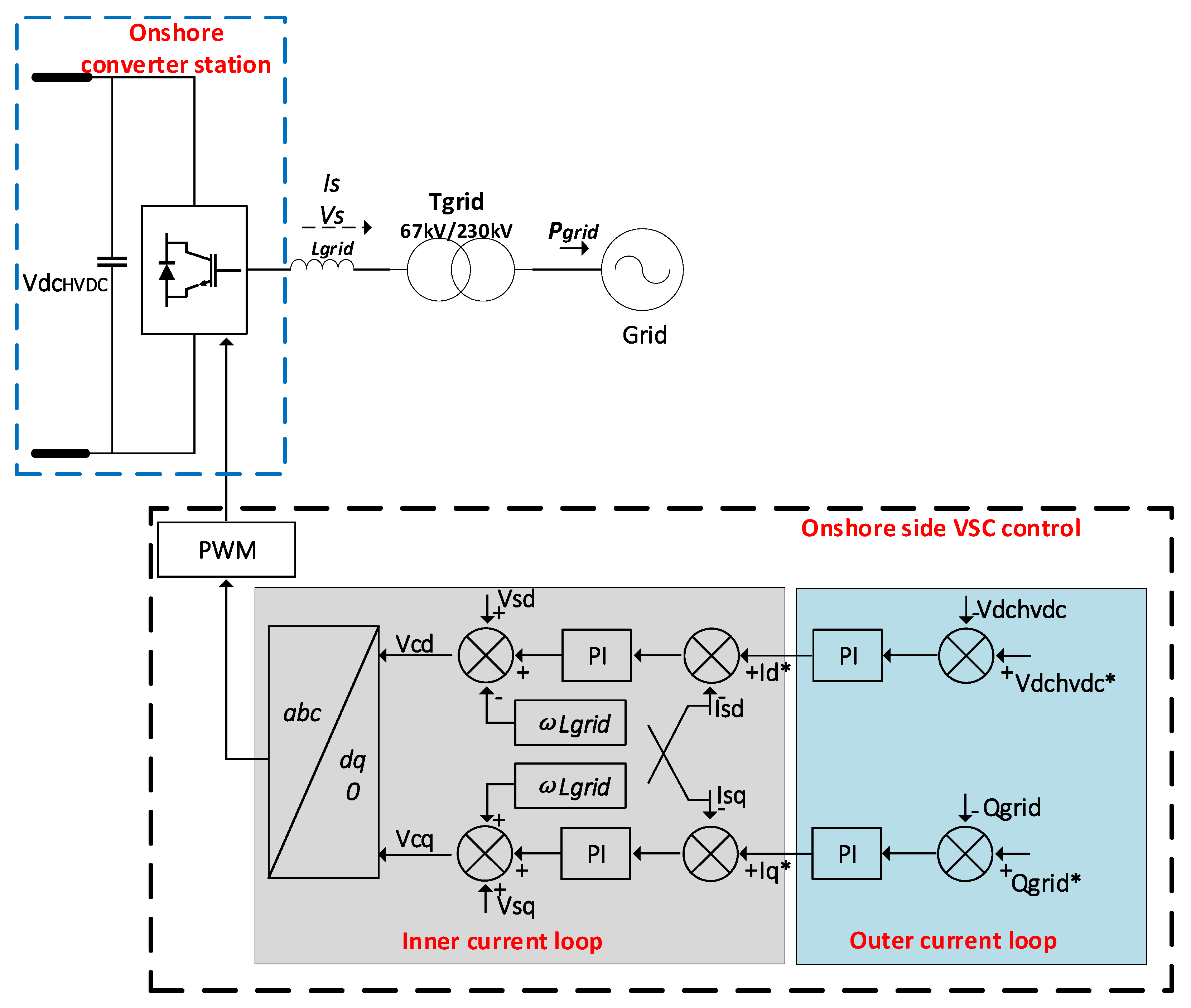
3.1. Control of the Onshore Converter

The ON-VSC outer control loop regulates the DC voltage of the HVDC system and provides reactive power support to the AC grid. The inner control loop controls the AC current and provides fast response [9,14]. The block diagram of the ON-VSC control system is shown in Figure 2.

3.1.1. Inner Current Control

The inner current control loop is implemented in the dq frame by using (1) and (2) [15]:
V g d = v d * I s q ω L g r i d + v s d ,
V g q = v q * I s d ω L g r i d + v s q ,
where ω is the angular frequency of the onshore AC grid. The Lgrid is the inductance of the coupling reactor. v s d and v s q are the dq components of the ON-VSC, Vgd and Vgq are the dq components of AC grid, I s d and I s q are the dq components of the current flowing into the grid (is). In this study, the Sinusoidal Pulse Width Modulation (SPWM) was used for PWM generation [15].

3.1.2. Outer Control Loop

According to [3], there are four options for the outer control loop:
  • Active power control mode;
  • DC voltage control mode;
  • Reactive power control mode;
  • AC voltage control mode.
The choice of control mode is decided based on the application (only one control mode is used per frame at a time, one is d frame and other in q frame) [3,16]. In this case, the ON-VSC was used for DC voltage and reactive power control.

3.2. Offshore Converter Control

The offshore converter is a hybrid converter that consists of a 6P-DR and a 2L-VSC for offshore converter stations. As the diode rectifier is uncontrollable, the VSC takes charge of all control aspects. In this research, the VSC controlled the offshore AC voltage and performed harmonic cancellation. The active power P and reactive power Q flowing into the OF-VSC are expressed as [11]:
P = | V O F V S C | sin γ X L · n | V p c c | ,
Q = | V O F V S C | cos γ X L · n | V p c c | ,
X L = ω P C C L v s c ,
where | V O F V S C | and | V P C C | are the voltage magnitudes of the OF-VSC and PCC, respectively. n is the voltage ratio of transformer T v s c , ω p c c is the angular frequency of the PCC voltage, L v s c is the reactance of OF-VSC, and γ is the phase shift between OF-VSC voltage and PCC voltage.
The block diagram of the hybrid converter control system is shown in Figure 3. As seen in Figure 3, the offshore wind farm is regarded as a single current source connected directly to the 33 kV offshore feeder. This simplification omits the voltage transformation between the low voltage at the terminal of the wind turbine (usually 690 V) to the offshore feeder voltage, however since the object of study of this research was not the wind farm itself but the hybrid offshore HVDC system, this simplification reduced the complexity of the simulation model.
The OF-VSC establishes the AC voltage and frequency at the wind farm PCC. Due to the connection of the 6P-DR transformer, the fifth and seventh harmonics appear in the current at the PCC, so the OF-VSC operates as an active filter to suppress these harmonics. As mentioned in Section 1, the controller is developed using a synchronous reference frame (SRF). The output from the SRF controller and AC voltage controller results in the voltage reference for the SPWM.

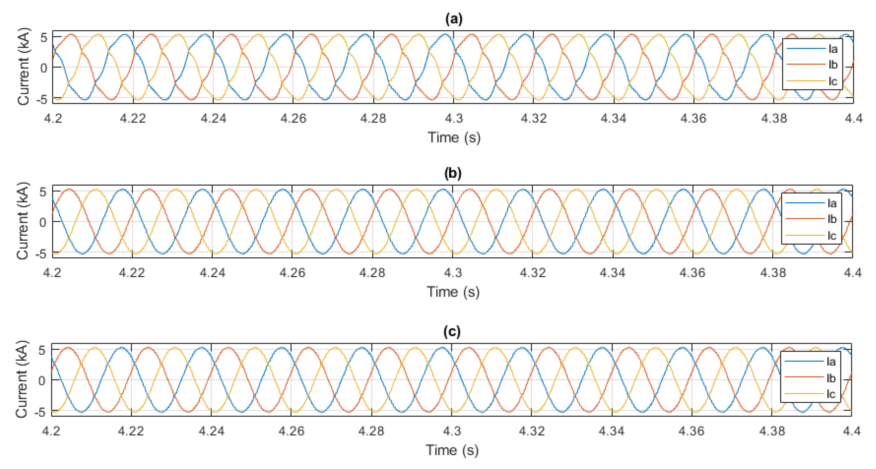
3.3. Harmonic Mitigation Using SRF-Based Controller

A considerable number of publications made use of proportional-resonant controllers to provide active power filtering capabilities to voltage source converters. The proportional-resonant (PR)-based controllers [17,18,19] can follow the sinusoidal harmonic reference at their respective resonant frequencies by introducing an infinite gain at the desired frequency without a steady-state error. PR-based controllers can provide fast responses but their tuning is complex. This is because the controller resonant frequency should be well-tuned to the reference frequency, as the infinite gain band is narrow, making this control method susceptible to grid frequency variations. Non-ideal PR-based controllers use a second-order integrator, which produces a wider resonant frequency band but increases tracking error [20].
The synchronous reference frames (SRF)-based controller [18] applies several synchronous dq harmonics frames and low-pass filters to detect the harmonics currents. The control signal passes through the low-pass filter on to the PI controllers. The advantage of using an SRF-based controller is that each harmonic component is transformed mathematically into two dq DC signals, where easy-to-tune PI controllers provide stable control with no tracking error. In addition, an active power filter using an SRF-based controller is not affected by changes in grid frequency. The main disadvantage of an SRF-based controller for harmonics suppression is a slow response due to delays introduced by the low-pass filter [20]. In this research, the SRF solution is preferred, given its robustness and easiness to deploy. Figure 4 shows the current harmonics mitigation strategy in the hybrid converter based on SRF. The current is measured at the PCC, 6P-DR and OF-VSC. The harmonic currents of the 6P-DR are compensated by the 2L-VSC using multiple SRF control topology [21].
The conventional process of detecting the current harmonics generated by the diode rectifier with the SRF-based controller is shown in Figure 5. As seen in Figure 5, the current harmonics are fed to different harmonic dq transformations, which are rotating at particular harmonic frequencies (i.e., 5th, 7th, 11th, and 13th harmonic frequencies). The output of the harmonic dq transformations is a signal that comprises a DC value and an AC value. The DC value represents the d and q components of the harmonic current, whereas the AC signal contains the rest of the harmonic components (and the fundamental AC signal).
The low-pass filter (LPF) aims to remove the AC part of the harmonic currents after being transformed by the harmonic dq frame [22]. The filtered dq component of the harmonic currents is used as a reference for the different PI controllers of the control system. The controller action of the different PIs produces harmonic dq modulator signals that will drive the OF-VSC to generate harmonic currents of the same magnitude but with a 180-degree angle shift to those found in the current coming from the diodes. As such, the harmonic currents from the diode rectifier will cancel each other out with the harmonic currents of the OF-VSC at the point of common coupling. To produce these harmonic modulator signals in the controllers of the OF-VSC, a dq to abc conversion is carried out using multiples of the synchronous frequency as its input. To ensure every harmonic current does not exceed the allowed range, every PI controller has a saturation limit. Without a saturation limit, the magnitude of the reference voltage of the VSC would be greater than the allowed voltage of the DC capacitor, which may result in saturation in the modulation signal to produce unwanted harmonic signals and would impact on the quality of the PCC current. This control approach can select to compensate individual current harmonics, according to the grid requirement, selecting a single or a group for compensation [15]. In this study, the fifth and seventh harmonic currents of the 6P-DR had a greater impact on total harmonic distortion (THD), given its transformer connection. Therefore, these components were chosen for compensation.
Equation (6) below presents the generalized harmonics dq transformation Tn based on the SRF technique to achieve dq components of the n harmonics, where Γn = sign [sin(2πn/3)] represents the sequence of the n harmonics and is reflected as an algebraic sign.
T n = 2 3 ( sin ( Γ n n ( ω s t ) ) sin ( Γ n n ( ω s t 2 π / 3 ) ) sin ( Γ n n ( ω s t + 2 π / 3 ) ) cos ( Γ n n ( ω s t ) ) cos ( Γ n n ( ω s t 2 π / 3 ) ) cos ( Γ n n ( ω s t + 2 π / 3 ) ) 1 / 2 1 / 2 1 / 2 ) .
The application of Tn to a given three-phase AC signal results in DC dq0 signals that represent the n harmonic, plus an AC component which includes all the non-n harmonics in the signal. These non-n harmonics are translated into frequencies that depend on the sequence of the n harmonic and the sequence of the rest of harmonics. Equation (7) shows the d and q harmonic currents calculation:
i n _ d = Γ n i n cos ( β n ) + k = 1 , k n Γ k i k cos ( Γ k [ ( Γ n n Γ k k ) ( ω s t ) ] + β k ) ,
i n _ q = i n sin ( β n ) + k = 1 , k n i k sin ( Γ k [ ( Γ n n Γ k k ) ( ω s t ) ] + β k ) ,
where i n _ d and i n _ q are the n harmonics dq signals, and β n is the phase shift of the n harmonic, i n is the n harmonic magnitude, i k is the magnitude of the k harmonic current, ω s is the synchronous frequency in radians, t is the time, β k is the phase shift of the k harmonic, and Γ k = sign [ sin ( 2 π k / 3 ) ] represents the sequence of the k harmonic and is reflected as an algebraic sign.
The dynamics of the dq fundamental and harmonics currents between the VSC and the PCC point are given by,
v n _ d _ v s c = r i n _ d + L d i n _ d / d t ω s L i n _ q v d ,
v n _ q _ v s c = r i n _ q + L d i n _ q / d t ω s L i n _ d v q ,
where r and L are the equivalent resistance and inductance between the VSC and the wind farm, i n _ d and i n _ q are the average dq current components of n harmonics, v n _ d _ v s c and v n _ q _ v s c are the dq voltage components of n harmonics of average voltages by the VSC, and where v d and v q are the dq voltage components of the PCC point. The transfer functions between dq fundamental and harmonic currents and the dq fundamental and harmonics voltage can be represented by the same equation if the grid voltage ( v d   and   v q ) and the cross coupling term ( ω s L i n _ q   and   ω s L i n _ d ) from Equations (9) and (10) are considered as disturbances. The relationships between the current and voltage in the dq frame are shown in Equation (11):
i n _ d ( s ) v n _ d _ v s c ( s ) = i n _ q ( s ) v n _ q _ v s c ( s ) = i n ( s ) v n _ v s c ( s ) = G i ( s ) = 1 L s + r .
As seen in Equation (11), the open-loop system has a stable pole at r / L , which can be cancelled by the PI controller.   K p i n v _ h and K i i n v _ h are the proportional and integral constants of the h harmonic PI current controller. The value of K i i n v h / K p i n v h = r / L and K p i n v h / L = 1 / τ i n v _ h , where τinv h is the time constant of the close-loop system. Equation (12) shows a close-loop transfer function for the h harmonic current controller, where τinv h can be selected based on the desired speed of response of the closed loop system:
B v s c _ h = 1 / ( τ v s c h S + 1 ) .

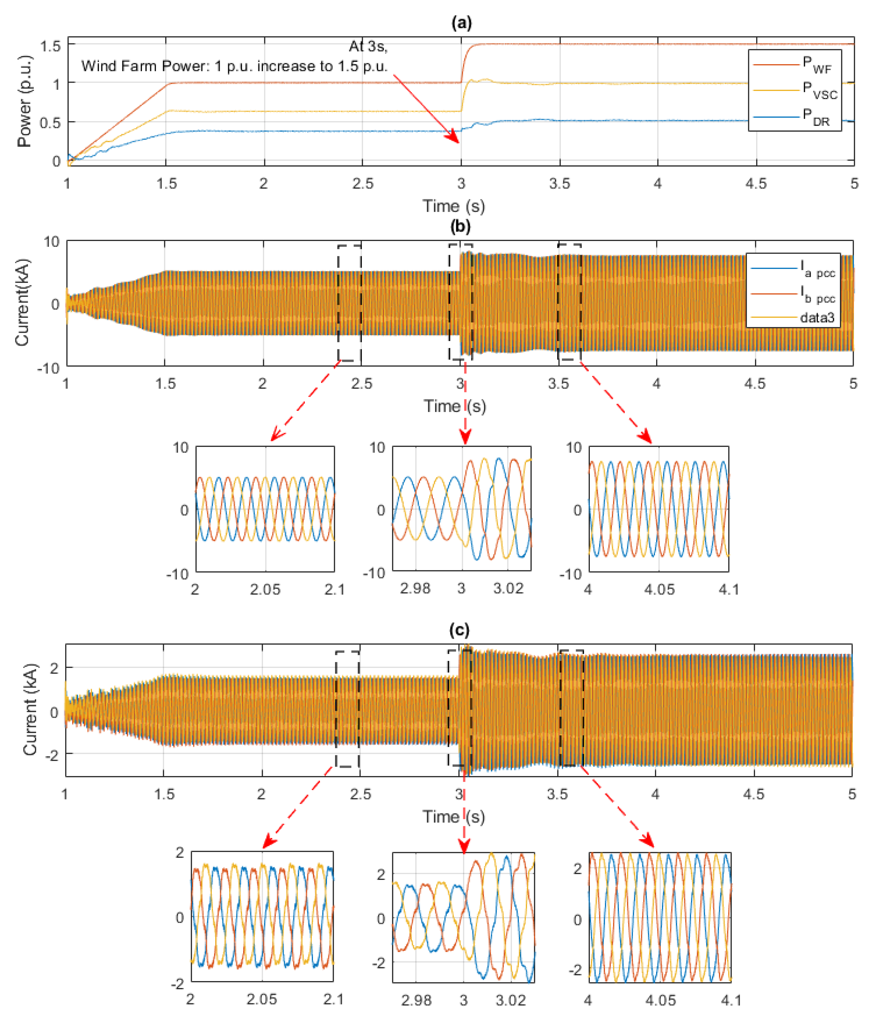
4. Simulation Results

The system shown in Figure 1 was simulated in a PSCAD/EMTDC environment to verify the proposed control of the hybrid HVDC system. The system parameters are listed in Table 1. The VSC and diode rectifier were implemented using detailed switched models, given their relevance for this study. On the other hand, the wind farm was implemented using controlled current sources synchronized with the grid using a phase locked loop (PLL) using grid voltage orientation, as seen in Figure 3. This simplification of the dynamics of the wind farm was enough to prove the concept of parallel operation of the converters in the offshore station.
The simulations provided in this section show the basic function of a hybrid HVDC system and the dynamics of the AC voltage in the offshore network. The simulations also show the harmonics cancellation dynamics for the 5th, 7th, 11th, and 13th harmonics’ currents.
The proposed control system first enabled an onshore converter station, providing the initial energy to the offshore station. The start-up sequence is shown in Table 2.
In Figure 6, at 0 s, the onshore converter station was enabled, which established the DC link voltage of the system at 1 p.u. (200 kV), in order to provide initial energy for the hybrid converter to start. At 1 s, the hybrid converter station and WF were enabled, and the OF-VSC started operating in AC voltage controller mode to provide AC voltage equal to 1 p.u. (33 kV) at the PCC point (Vacpcc). During 1.0–1.5 s, the generated active power from the 200 MW WF increased from 0 MW to 200 MW (1 p.u.), at the same time, the 200 MW WF was synchronized with the offshore HVDC system. The harmonic compensation from the OF-VSC was enabled after 1.5 s.
Due to the series configuration, the diode rectifier and VSC in the hybrid converter share the HVDC DC-link voltage (VdcHVDC). Figure 6b shows the DC voltage from the diode rectifier (VdcDR) and the VSC (VdcVSC). The active power generated by the wind farm (PWF), the active power of the diode rectifier (PDR), and the active power of the VSC (PVSC) are shown in Figure 6c. As seen in Figure 6b,c, power flowing through the diode rectifier and the VSC was proportional to the magnitude of the DC voltage of the diode rectifier and VSC, respectively.
The AC voltage control establishes the AC voltage at the PCC. Figure 7 shows the offshore AC voltage magnitude during the setpoint change. At the beginning, OF-VSC control V p c c was at 1 p.u., at 3 s, AC voltage reference was reduced to 0.96 p.u., then the reference was increased to 1.10 p.u. at 5 s and reduced back to 1 p.u. at 7 s.
The results of harmonics current cancellation are presented in Figure 8. Figure 8a shows the current at PCC without any harmonics compensation, Figure 8b,c show the PCC current with harmonic currents compensation. In order to compare the performance of the SRF controller, Figure 8b shows the harmonics compensation at the PCC when both the fifth and seventh controllers were active. Finally, the full compensation of all the relevant harmonics in the PCC (5th, 7th 11th, and 13th) is shown in Figure 8c.
The results of Figure 8 show the PCC current waveforms for the same period. The current waveforms presented high harmonic content without the SRF controller. After the SRF controller was enabled, the waveform looks harmonic-free. In order to confirm the results of SRF harmonics control, Figure 9 shows the PCC phase current harmonics spectrum, calculated using Fast Fourier Transform (FFT). The results confirm that the 5th, 7th, 11th, and 13th harmonic components were supressed by the SRF controller action. In addition, Table 3 displays the effect of each harmonic controller and the corresponding THD of the PCC current.
In order to test the perfomance of the OF-VSC to changing harmonic content in the PCC currents, a power step from the WF was simulated. Such a power step increased the amout of current flowing through the 6P-DR and in consequence affected the magnitude of the circulating harmonic currents.
As seen in Figure 10, at 1 s, the WF generated 1 p.u. power to the onshore grid, at 3 s the WF increased its power output to 1.5 p.u., as shown in Figure 10a. The current at PCC quickly increased as shown in Figure 10b, at 3 s, the PCC current increased and led to larger harmonic currents that temporarily increased the total harmonic distortion on the PCC currents. This increase in harmonic distortion triggered a corrective action from the OF-VSC, which in turn increased its compensating harmonic currents. As seen in Figure 10b, after a period (this period was dictated by the time constant of the closed loop harmonic controller) the PCC currents turned again harmonic free. Figure 10c shows the OF-VSC currents after and before the power step. As seen in the figure, the amount of harmonic currents that the OF-VSC provided to the PCC changed based on the amount of the total harmonic distortion at the PCC.

5. Conclusions

This paper proposed a novel grid forming control and harmonics mitigation control for a hybrid HVDC system. Unlike previous hybrid converters, that consist of 12P-DR and VSC, such as the one presented in [11], the proposed hybrid converter uses a 6P-DR connected in series with a VSC converter, which reduces the associated cost of the system (i.e., no need for a three winding transformer, reduced number of diodes, less platform space, smaller AC reactors). The simulation showed that the hybrid HVDC system connects can interact with dq0-controlled wind turbines, such as full converter PMSG ones. The proposed control system is able to simultaneously control the offshore AC voltage and reduce the main harmonics current at the PCC. The method to detect and cancel harmonics in the HVDC provides zero harmonic current steady state error thanks to the use of PI controllers. Since the current magnitudes in the offshore network change based on the time constants of the incoming wind power, the speed of response of the proposed solution is sufficient to compensate harmonic currents in steady state.
Future work will focus on the control of DC voltage of the OF-VSC system. The DC voltage control may control the power share between the diode rectifier and the OF-VSC. This feature can be used to reduce the size of the OF-VSC even further, and thus reduce its cost.

Author Contributions

Conceptualization, O.A.-L.; methodology, S.T., D.C.-G. and V.A.L.; software, S.T.; validation, S.T., D.C.-G. and O.A.-L.; formal analysis, S.T.; investigation, S.T.; resources, O.A.-L., R.E.T.-O. and D.C.-G.; data curation, S.T.; writing—original draft preparation, S.T.; writing—review and editing, S.T., D.C.-G., V.A.L. and O.A.-L.; visualization, S.T.; supervision, O.A.-L. and D.C.-G.; project administration, O.A.-L. All authors have read and agreed to the published version of the manuscript.

Funding

This work was funded in part by the São Paulo Research Foundation (FAPESP), (grant number 2018/10667-6).

Conflicts of Interest

The authors declare no conflict of interest.

References

  1. Kalair, A.; Abas, N.; Khan, N. Comparative study of HVAC and HVDC transmission systems. Renew. Sustain. Energy Rev. 2016, 59, 1653–1675. [Google Scholar] [CrossRef]
  2. Power, B. Offshore Wind Energy Generation: Control, Protection, and Integration to Electrical; John Wiley & Sons: Hoboken, NJ, USA, 2014; pp. 138–140. [Google Scholar]
  3. Korompili, A.; Wu, Q.; Zhao, H. Review of VSC HVDC connection for offshore wind power integration. Renew. Sustain. Energy Rev. 2016, 59, 1405–1414. [Google Scholar] [CrossRef] [Green Version]
  4. Blasco-Gimenez, R.; Añí-Villalba, S.; Rodríguez-D’Derlée, J.; Bernal-Perez, S.; Morant, F. Diode-based HVdc link for the connection of large offshore wind farms. IEEE Trans. Energy Convers. 2011, 26, 615–626. [Google Scholar] [CrossRef]
  5. Bernal-Perez, S.; Ano-Villalba, S.; Blasco-Gimenez, R.; Rodriguez-D’Derlee, J. Efficiency and fault ride-through performance of a diode-rectifier-and VSC-inverter-based HVDC link for offshore wind farms. IEEE Trans. Ind. Electron. 2013, 60, 2401–2409. [Google Scholar] [CrossRef]
  6. Yu, L.; Li, R.; Xu, L. Distributed PLL-based Control of Offshore Wind Turbine Connected with Diode-Rectifier based HVDC Systems. IEEE Trans. Power Deliv. 2017, 33, 1328–1336. [Google Scholar] [CrossRef] [Green Version]
  7. Yu, L.; Li, R.; Xu, L. Hierarchical control of offshore wind farm connected by parallel diode-rectifier-based HVDC and HVAC links. IET Renew. Power Gener. 2019, 13, 1493–1502. [Google Scholar] [CrossRef] [Green Version]
  8. Yu, L.; Li, R.; Xu, L. Parallel operation of diode-rectifier based HVDC link and HVAC link for offshore wind power transmission. J. Eng. 2019, 2019, 4713–4717. [Google Scholar] [CrossRef]
  9. Seman, S.; Trinh, N.T.; Zurowski, R.; Kreplin, S. Modelling of the Diode-Rectifier Based HVDC Transmission Solution for Large Offshore Wind Power Plants Grid Access. In Proceedings of the International Workshop on Large-Scale Integration of Wind Power into Power Systems, Vienna, Austria, 15–17 November 2016. [Google Scholar]
  10. Ramachandran, R.; Poullain, S.; Benchaib, A.; Bacha, S.; Francois, B.; de Lille, E.C. AC Grid Forming by Coordinated Control of Offshore Wind Farm connected to Diode Rectifier based HVDC Link–Review and Assessment of Solutions Acknowledgments Keywords. In Proceedings of the 2018 20th European Conference on Power Electronics and Applications (EPE’18 ECCE Europe), Riga, Latvia, 17–21 September 2018; pp. 1–10. [Google Scholar]
  11. Nguyen, T.H.; Lee, D.C.; Kim, C.K. A series-connected topology of a diode rectifier and a voltage-source converter for an HVDC transmission system. IEEE Trans. Power Electron. 2014, 29, 1579–1584. [Google Scholar] [CrossRef]
  12. Nguyen, T.H.; Le, Q.A.; Lee, D.C. A Novel HVDC-Link based on Hybrid Voltage-Source Converters. In Proceedings of the 2015 IEEE Energy Conversion Congress and Exposition (ECCE), Montreal, QC, Canada, 20–24 September 2015; pp. 3338–3343. [Google Scholar]
  13. Nguyen, T.H.; Lee, D.C.; Kim, C.K. A Cost-Effective Converter System for HVDC Links Lntegrated with Offshore Wind Farms. In Proceedings of the IECON 2013-39th Annual Conference of the IEEE Industrial Electronics Society, Vienna, Austria, 10–13 November 2013; pp. 7978–7983. [Google Scholar]
  14. Li, S.; Haskew, T.A.; Swatloski, R.P.; Gathings, W. Optimal and direct-current vector control of direct-driven PMSG wind turbines. IEEE Trans. Power Electron. 2012, 27, 2335–2337. [Google Scholar] [CrossRef]
  15. Monroy-Morales, J.L.; Campos-Gaona, D.; Hernández-Ángeles, M.; Peña-Alzola, R.; Guardado-Zavala, J.L. An active power filter based on a three-level inverter and 3D-SVPWM for selective harmonic and reactive compensation. Energies 2017, 10, 297. [Google Scholar] [CrossRef] [Green Version]
  16. Wu, G. Analysis and design of vector control for VSC-HVDC connected to weak grids. CSEE J. Power Energy Syst. 2017, 3, 115–124. [Google Scholar] [CrossRef]
  17. Liserre, M.; Teodorescu, R.; Blaabjerg, F. Multiple harmonics control for three-phase grid converter systems with the use of PI-RES current controller in a rotating frame. IEEE Trans. Power Electron. 2006, 21, 836–841. [Google Scholar] [CrossRef]
  18. Asiminoaei, L.; Blaabjerg, F.; Hansen, S. Evaluation of Harmonic Detection Methods for Active Power FilterApplications. In Proceedings of the Twentieth Annual IEEE Applied Power Electronics Conference and Exposition, Austin, TX, USA, 6–10 March 2005; Volume 1, pp. 635–641. [Google Scholar]
  19. Herman, L.; Papic, I.; Blazic, B. A proportional-resonant current controller for selective harmonic compensation in a hybrid active power filter. IEEE Trans. Power Deliv. 2014, 29, 2055–2065. [Google Scholar] [CrossRef]
  20. Campos-Gaona, D.; Pena-Alzola, R.; Monroy-Morales, J.L.; Ordonez, M.; Anaya-Lara, O.; Leithead, W.E. Fast selective harmonic mitigation in multifunctional inverters using internal model controllers and synchronous reference frames. IEEE Trans. Ind. Electron. 2017, 64, 6338–6349. [Google Scholar] [CrossRef] [Green Version]
  21. Chen, G.; Zhu, M.; Cai, X. Medium-voltage level dynamic voltage restorer compensation strategy by positive and negative sequence extractions in multiple reference frames. IET Power Electron. 2014, 7, 1747–1758. [Google Scholar] [CrossRef]
  22. Morales, J.L.M.; Ángeles, M.H.; Campos-Gaona, D.; Peña-Alzola, R. Control Design of a Neutral Point Clamped Converter based Active Power Filter for the Selective Harmonic Compensation. In Proceedings of the 2016 IEEE PES Transmission & Distribution Conference and Exposition-Latin America (PES T&D-LA), Morelia, Mexico, 20–24 September 2016. [Google Scholar]
Figure 1. Proposed topology: offshore wind farm connected to a hybrid converter.
Energies 13 01681 g001
Figure 2. Control block diagram of the onshore two-level voltage source converter (ON-VSC).
Energies 13 01681 g002
Figure 3. Control block diagram of the offshore VSC (OF-VSC) and wind farm (WF).
Energies 13 01681 g003
Figure 4. The harmonics mitigation in the hybrid converter.
Energies 13 01681 g004
Figure 5. Synchronous reference frame (SRF)-based controller.
Energies 13 01681 g005
Figure 6. (a) Offshore voltage magnitude at the point of common coupling (PCC), (b) DC voltage of HVDC and hybrid converter, (c) converters’ active power.
Energies 13 01681 g006
Figure 7. (a) The offshore AC voltage magnitude during voltage command change (b) the instantons voltage of offshore AC voltage.
Energies 13 01681 g007
Figure 8. (a) Current at PCC—no harmonic compensation, (b) current at PCC—5th and 7th harmonics compensated. (c) Current at PCC—5th, 7th, 11th, and 13th harmonics compensated.
Energies 13 01681 g008
Figure 9. Current frequency spectrum. (a) No harmonics compensation, (b) 5th and 7th harmonic compensation. (c) 5th, 7th, 11th, and 13th harmonic compensation.
Energies 13 01681 g009
Figure 10. (a) Power flow through the different components of the offshore system. (b) The PCC current. (c) The current flowing through OF-VSC.
Energies 13 01681 g010
Table 1. Parameter of the hybrid HVDC system.
ComponentsParametersValue
Wind FarmPower rating200 MW
Offshore 6-PDInput inductance (Ldr)46.5 mH
Offshore 6-PDDC filter capacitance200 µF
Offshore 6-PDTransformer Tdr (Y/D)33/67 kV; 0.1 p.u.
Offshore 2L-VSCInput inductance (Lvsc)46.5 mH
Offshore 2L-VSCDC filter capacitance200 µF
Offshore 2L-VSCTransformer Tvsc (Y/D)33/67 kV; 0.1 p.u.
Onshore 2L-VSCInput inductance (Lgrid)46.5 mH
Onshore 2L-VSCDC filter capacitance400 µF
Onshore 2L-VSCTransformer Tgrid (D/Y)67/230 kV; 0.1 p.u.
Table 2. Start-up sequence.
TimeEvents
0 sOnshore station enabled, provides DC link voltage to offshore station
1 s–1.5 sOffshore station and WF enabled, establishes AC voltage and frequency
Table 3. The current total harmonic distortion (THD) with and without SRF.
Harmonics Compensation%Total Harmonic Distortion (THD)
None8.43%
5th and 7th1.71%
5th, 7th, 11th, and 13th 0.06%

