1. Introduction
The International Maritime Organization (IMO) policies changes related to the global control of emissions included in the International Convention for the Prevention of Pollution from ships: MARPOL-Annex VI, followed by IMO 2020 Sulphur Limit compliance with the 1 January, 2020 deadline, not only forced ship owners/ managers to comply with the provisions of the Convention, but above all, had an impact on far-reaching consequences on shipping company operating costs, global freight rates, low sulfur fuels or scrubber demands, accelerated ship scrappage, and more. It necessitated the use of fuel oils with low sulfur content called low-sulfur fuels, and in many cases, has ruled out the use of residual fuel to distillate fuels. Next, it is observed that the steadily deteriorating quality of fuel oils combined with increased content of catalytic additives (cat-fines) used in the refining processes of crude oil, caused the problem of the deterioration of working conditions in fuel system precision pairs. According to the literature [
1] and the author’s own experience, it has become significant, with respect to, therefore, accelerated wear occurring in the fuel injectors and injection pumps, and then following, operational problems. In addition, as it follows from an analysis of operational reports and author research [
2,
3] that damage to injection systems, apart from poor quality fuel, is also caused by increasingly worsening quality of materials used for atomizers and spare parts of injection pumps (service life is almost half shorter compared to one or two decades ago). The damage to the injection system for medium size ships (length 200 to 250 m) accounts for approximately 50–70% [
3].
The inability to on-line diagnose and monitor the condition of injection systems often leads to secondary damages, such as a burnt, torn off atomizer nose or coking of atomizer holes, as shown in
Figure 1a, and damages to the fuel injector’s blown by seats and, as a consequence, damage to the cylinder head, as shown in
Figure 1b,c. These defects result in improper fuel spray, or carbon deposit on piston ring grooves. Consequently, sealing rings get cracked, the crankshaft load is uneven, and this leads to more serious damage or failures of the entire engine.
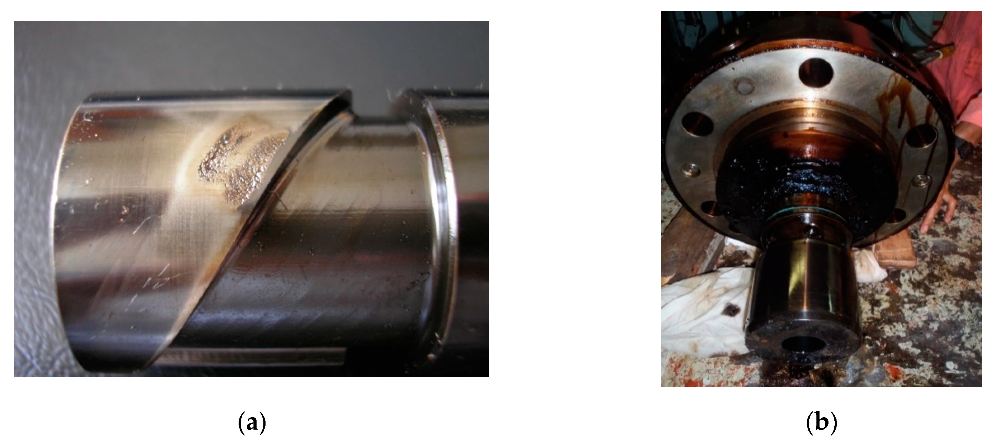
The general principle of the operation of the fuel injection pump (FIP) with a rotary plunger consists in delivering fuel by reciprocating motion of the plunger in the barrel. Fuel dose regulation is enabled by the helix edge on the plunger. Such pumps are subject to tribological abrasive wear caused by poor quality fuels with high cat-fines content, resulting in increased plunger-barrel clearance, as well as erosion and high pressure cavitation, as shown in
Figure 2.
The aim of this article is to present the author’s developed method for condition assessing and identifying the limit condition of the tribological system, applicable to the two-stroke crosshead and the four-stroke trunk piston diesel engines, and their fuel injection pump’s precision pair, to find early stage worn out symptoms to avoid break downs.
2. Materials and Methods
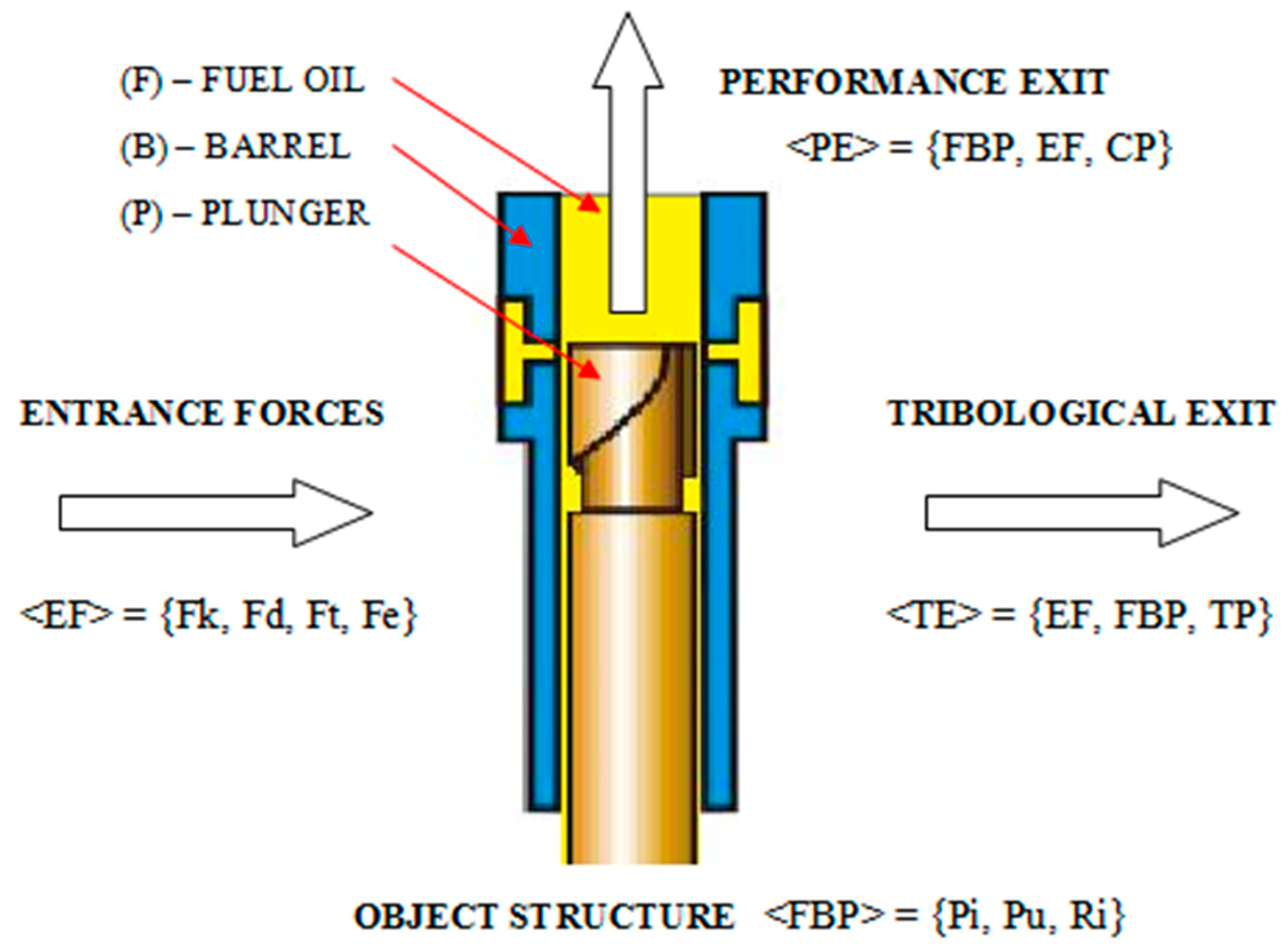
The main part of the fuel injection pump (FIP) is its hydraulic precision pair, which consists of two elements: the cylinder, called barrel (B), and piston, called plunger (P). They are separated by working fluid, in this case fuel oil (F), which forms the third structural element of the machine, and, at the same time, works in recirculation with fresh fuel oil corresponding to feed rate, performing the following functions: lubricating, cooling, and sealing. Thus, fuel oil-barrel-plunger (FBP) elements, as shown in
Figure 3, constitutes tribological node. The most susceptible to external/entrance forces (EF) in this node is fuel oil. Its quality, including content and amount of impurities, affects parameters of performance exit/output (PE), described by pump performance/efficiency (CP), and reflects on parameters of tribological exit/output (TE), characterizing tribological processes (TP).
The tightness of the plunger-barrel assembly that performs in a reciprocating–rotational motion is not ensured by sealing rings, but by application of minimum radial clearances. They vary in range of 5–25μm with a limit of 50μm, depending on the cylinder liner bore and power achieved by one cylinder [
3,
4]. Thus, the clearance measure is the utmost important parameter that binds responses of performance output (PE) and tribological exit (TE), whereas the input measures—external forces (EF) and performance output (PE)—are dependent on operational requirements.
From the practical point of view, the basic operational problem is to determine the current degree of precision pair wear. To date, no reliable diagnostic method has been developed for determining the limit wear condition of the plunger-cylinder unit. The authors have used elastic waves of acoustic emission (AE) for diagnostic purposes, including components of the injection system [
2,
4,
5,
6]. Relevant tests were conducted for three years on ships propelled by slow speed, two-stroke crosshead by MITSUBISHI type UEC or by MAN B&W type MC-C engines. Besides, similar results obtained from medium speed, four-stroke trunk piston Wartsila SW 380 engines were examined for the verification of the adopted hypotheses.
An AE measuring sensor of the developed diagnostic system is placed in way of the injection pump head as shown in
Figure 4. The signal is then transmitted to the dedicated recorder of AE elastic waves [
7,
8,
9]. The AE signal from an injection pump is recorded while the engine is working. The AE sensor was placed at the height of the pump plunger top, dead center. To avoid wave dispersion at the pump—sensor interface, a coupling liquid in the form of graphite lubricant was used between the sensor and pump body.
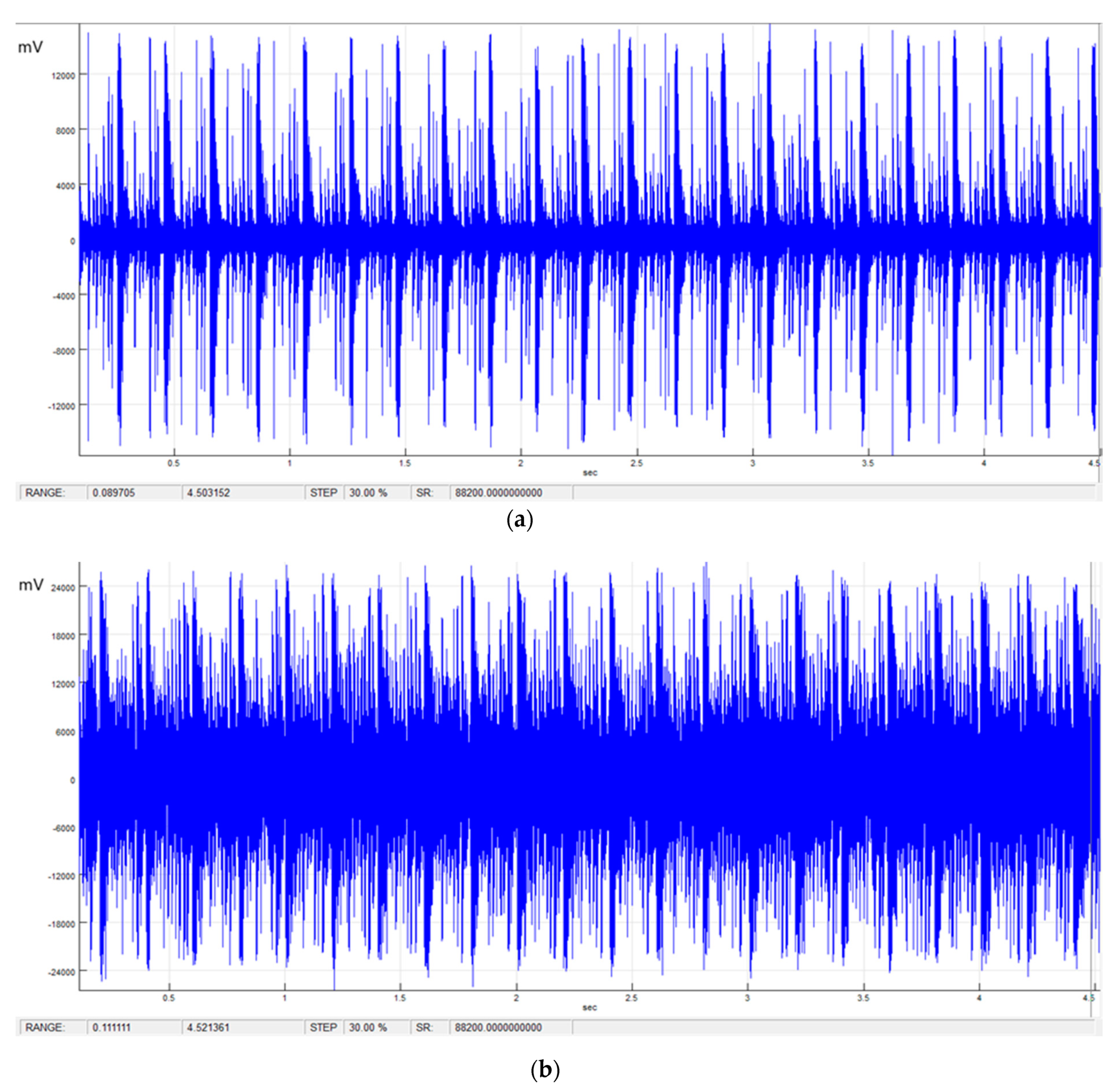
Figure 5 and
Figure 6 present the examples of AE source (raw) signals from, respectively, for a new fuel injection pump (FIP) and after 11,000 working hours measured at two-stroke MAN B&W 7S80MC-C and four-stroke Wartsila SW 380 engines.
For some time now, the authors have dealt with the applications of AE signals for diagnosing various mechanical systems and machines (e.g., injection systems of self-ignition engines [
2,
3,
5,
6,
10], valve units of drillship mud pumps [
8], or marine power electronic equipment [
8,
11]).
AE elastic waves reach the sensor, then are recorded by an appropriate measurement system. Their primary advantage is the relatively high frequency of recorded wave (15 kHz–1 MHz) comes from a close source, the other waves get suppressed. Acoustic emission is understood as propagating elastic wave. If an external cause emerges, such that it changes the state of the energy acquired during operation, its portion can be emitted in the form of elastic waves. Elastic waves are emitted by the source propagate through the material, subject to all laws associated with wave propagation [
12,
13]. The form of the propagating wave depends, inter alia, on certain characteristics of the medium in which it propagates, its material properties, wave frequency, etc. From the basic principle of acoustic emission measurement results, the advantage of the applied method distinguishes it from other methods of determination of physical and chemical properties of solids and liquids. The energy that is generated by the heterogeneity of the examined center, as a result of external stimulation or normal operation of the object, is also the source of the recorded signal. Besides, the spectrum of generated acoustic emission pulses is strictly dependent on phenomena occurring in the macro and microstructure of the material (e.g., the fuel injection pump). The spectral analysis allows us to determine the correlation of signal functions with various frequencies [
14,
15]. In the case of high correlation (high correlation coefficients for sine or cosine) the occurrence of visible periodicity in the given frequency can be expected. The greater the wear of the FIP precision pair, the greater the differences will be. Therefore, the authors proposed to analyze the spectrum of AE signals using the cross gain function to examine the possibility of determining frequencies characteristic of the specific limit of the fuel injection pump’s wear.
3. Analysis of Results and Discussion
Cross gain is the measure of contribution of the signal 1 frequency component in the cross spectrum of signal 1 (
x) and signal 2 (
y). To take full advantage of this analysis, we should perform both “signal 1 cross gain signal 2” and “signal 2 cross gain signal 1”. The analysis of the signals obtained consisted in a composition of two functions for signals coming from the pump with a new precision pair, and a pump where the precision pair reached a limit state (in this case, after 11,000 h and vice versa). It was first assumed that the function of ‘
x’ is a signal from the new pump, the other ‘
y’ from the worn pump. The cross spectrum f
xy can be written in the Cartesian coordinates:
Real-valued functions
cxy(
ω) and
qxy(
ω) are, respectively, cospectral density and squared density. Polar coordinates can be used instead of the Cartesian system: complex numbers are described by the coordinate system in which the abscissa
x axis contains real numbers and the ordinate
y axis contains imaginary numbers. Complex numbers may be presented as points of such a two-dimensional plane. Therefore, we can write:
The real-valued function
Rxy(
ω) and
fxy(
ω), are respectively, amplitude spectrum (gain), and the phase shift. The covariance
xt and
yt can be calculated as an integer of the cospectral density function. The cospectrum in the frequency
ω indicates which part of the covariance is responsible for fluctuations of frequency
ω. The cospectrum may assume positive values in some frequencies and negative values in other frequencies. The spectrum amplitude measures the strength of the linear relationship of the series/signals
xt and
yt in each frequency. The measure of the given relationship is the squared coherence function (square density):
The phase spectrum determines whether and how much
xt,
t ∈ N precedes or is delayed relative to
yt,
t ∈ N for various frequencies. An important element in the cross spectrum analysis is gain
yt (variable) relative to
xt (independent variable) and vice versa,
xt relative to
yt. Obtained from the analyses, the relations of characteristic frequencies can be directly connected with the degree of wear of an injection pump precision pair (plunger-barrel). Cross-spectral analysis informs us about the relationship between two signals in their frequency domain. The average cross spectrum in the most basic of all dual-channel functions. Many dual-channel spectrum analyzers do not permit the user to view the average-cross-spectrum function because, in and of itself, it has no useful analysis purpose. It is used to calculate all of other dual-channel functions because it is the most basic function retaining phase shift information between channels
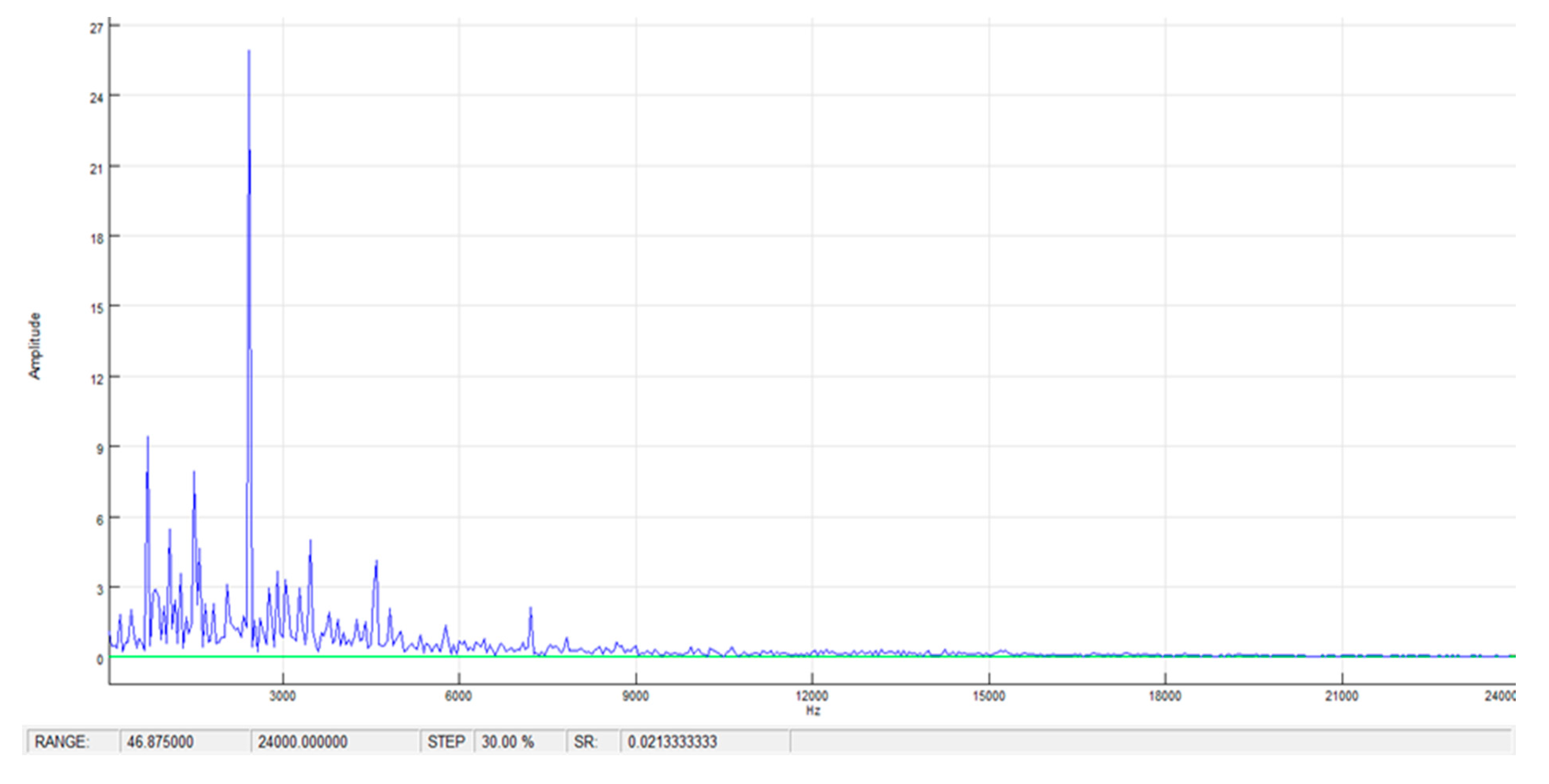
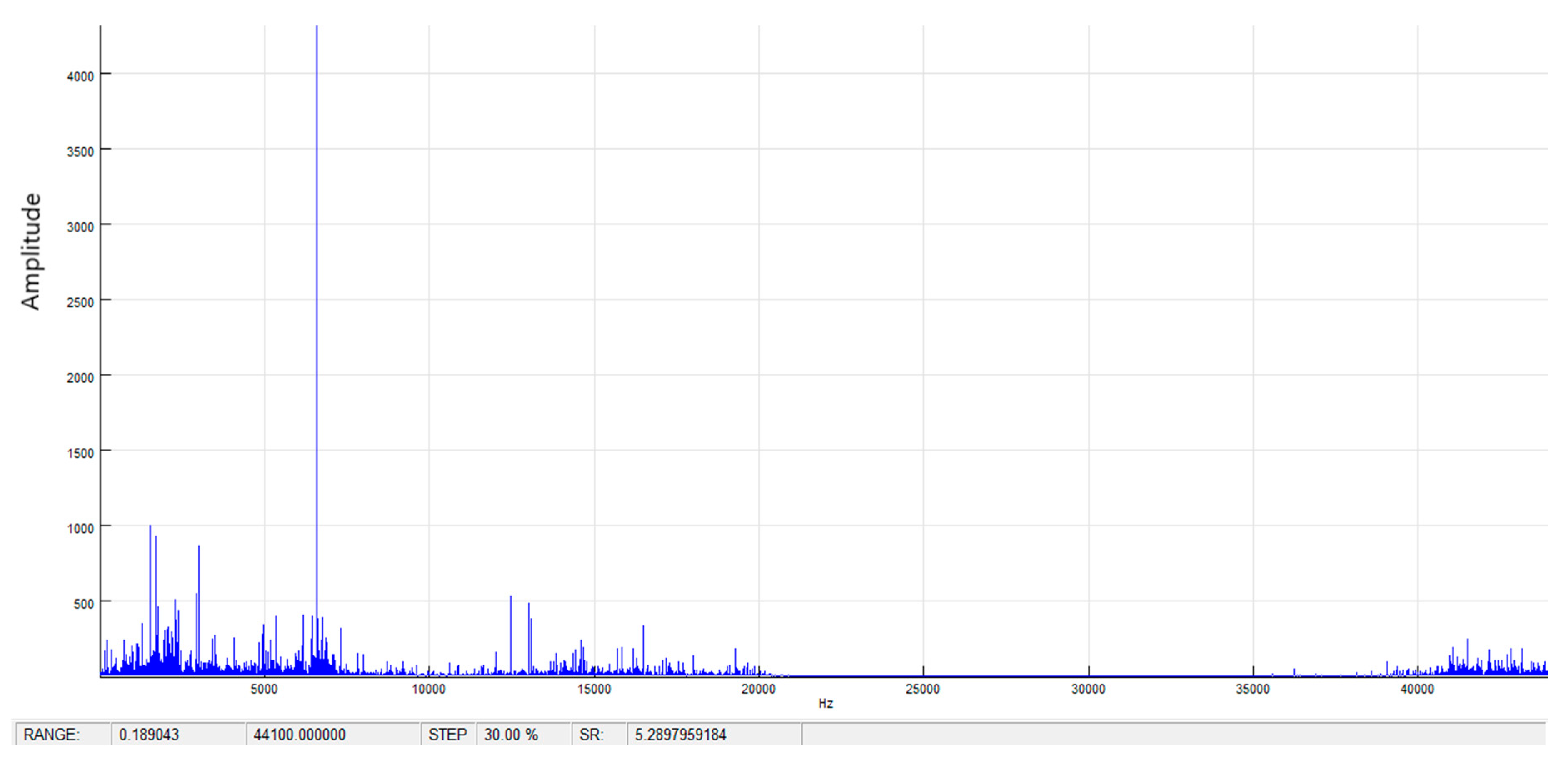
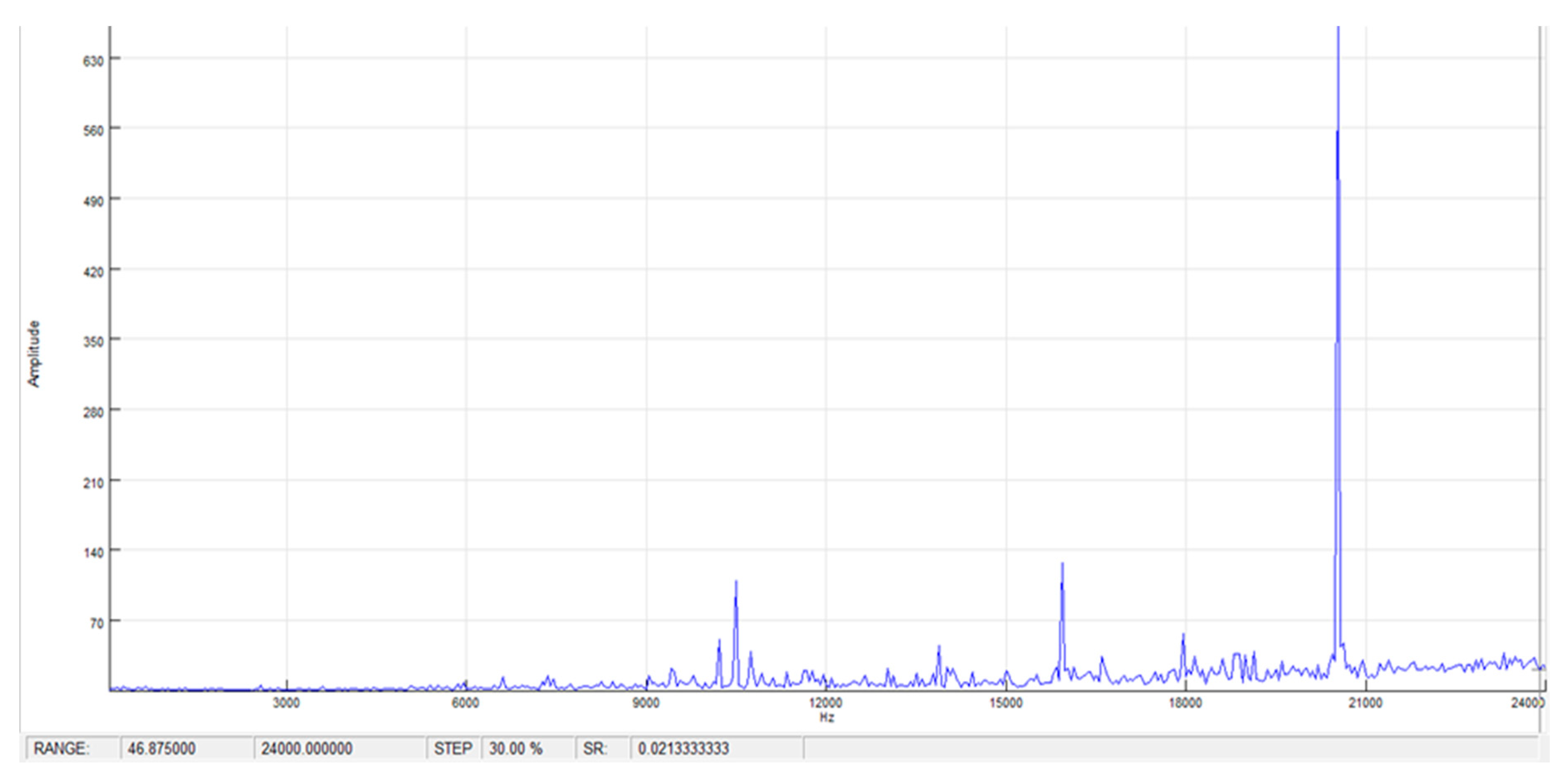
x, as shown in
Figure 7 and
Figure 8 for new fuel injection pump (FIP), and
y as shown in
Figure 9 and
Figure 10 for worn FIP. The average cross spectrum is calculated as the complex product of spectrum
Sy and the complex conjugate of
Sx [
12,
16].
The magnitude of the average cross spectrum indicates those frequencies where both
x(
t) and
y(
t) have content. The amplitude of the signals shown in
Figure 7,
Figure 8,
Figure 9 and
Figure 10 is the phase difference for the given frequencies [
12,
16].
Cross gain is the measure of contribution of signal x frequency component in the cross spectrum of signal x (new pump) and signal y (worn pump). A higher amplitude means that the first signal contributes more in the cross spectrum for that specific frequency.
It follows from the analysis that the acoustic emission signal from the new pump (after application of the cross gain function) generates characteristic frequencies associated mainly with a specific friction process. It is a frequency band of approximately 2–8 kHz. In the case of a pump with increased radial clearance of the plunger-barrel unit, friction is reduced as the gap between the plunger and the barrel gets larger. The characteristic frequency band above 20 kHz is related to fuel leaks and change in pump discharge pressure. An analysis of the above indicates that the use of the cross gain function allows us to determine the limit condition for a given type of fuel injection pump (FIP). The appearance of the characteristic frequency value (compared to the signal from the new FIP) makes it possible to accurately verify and evaluate the limit value of the technical condition of the pump. Using the cross gain function, we can demonstrate that when the acoustic emission signal from an examined pump (unknown technical condition) is superimposed on a signal from a new pump precision pair, the limit state associated with the wear of the component generates an enhanced signal amplitude in the range of 20 kHz.
4. Conclusions
On ships, inspections of fuel injection pumps (FIPs) come down to visual assessment of the plunger-barrel (P-B) pair, which is not sufficient, because it only allows to determine the operational condition of unfitness, or wear condition. Practically, it is performed only in case of FIP failure, and it leads to exchange of P-B pair. At present, available diagnosis methods of fuel injection pump assessment of technical conditions are based on measurements of combustion and injection processes. Commonly used in ship practices, measurements of pressure changes in the combustion chamber are very useful in evaluation of injection processes, but do not bring satisfactory results in FIP diagnosis. In turn, measurements of pressure changes during the injection process are not met in operation due to technical restrictions that enforce mounting of sensors on each fuel pipe. Considering the above, there is a necessity to search for methods that allow FIP diagnosis and condition monitoring during engine operation. This led to the authors’ interest in the subject, as well as to conduct research concerning diagnosing injection systems of high and medium power engines by using acoustic emission (AE) signals. The experiment results obtained with the use of acoustic emission and wavelet analysis were described and discussed in a previous article, published in the Special Issue of Energies: Diagnostics and Condition Monitoring Technologies for Assuring Asset Performances [
16]. It confirmed the dependency of the frequency components contained in the acoustic emission signal on the condition state of the injector pumps’ tribological pair. However, it did not allow to find the threshold of magnitude or intensity, when it occurred or exceeded above a certain value, then identifying the limit conditions, and pointing at the stage when further operations can lead to an accident. Therefore, the authors, based on previously obtained results, investigated a suitable method of AE signal analyses, allowing to find such thresholds.
It has been discussed in this article the diagnostic applicability of specific acoustic emission signal measures for assessing the technical conditions of fuel injection pumps, i.e., the degree of wear. The cross gain analysis, as combined, and the simultaneous spectrum analysis of two series, originating from two different AE signals for a new and a used FIP, was used for the identification of the limit condition of the plunger-barrel wear. Comparison of the cross gain function after a signal from a new fuel injection pump (FIP) is combined with a signal from the worn FIP, and vice versa, indicates a relationship between two series for the same frequencies, associated mainly with a specific friction process. Such application of the cross gain function allows FIP diagnosing while the engine is running and specifies precisely how close the plunger-barrel precision pair of the fuel injection pump is to the fault state.
In conclusion, it can be stated that the author’s developed method for assessing and identifying the limit condition of the tribological system is applicable for both the two-stroke crosshead and four-stroke trunk piston diesel engines, as well, and their fuel injection pump’s precision pair, to find early stage worn out symptoms, to avoid break downs.

