Article

Predictive Power Control of Novel N*3-phase PM Energy Storage Motor for Urban Rail Transit

1
College of Electrical and Information Engineering, Changsha University, Changsha 410022, China
2
College of Electrical and Information Engineering, Hunan University, Changsha 410082, China
3
College of Electrical and Information Engineering, Hunan University of Technology, Zhuzhou 412007, China
*
Authors to whom correspondence should be addressed.
Energies 2020, 13(7), 1578; https://doi.org/10.3390/en13071578
Submission received: 10 February 2020 / Revised: 19 March 2020 / Accepted: 20 March 2020 / Published: 1 April 2020

Abstract

:
High power density energy storage permanent magnet (PM) motor is an important energy storage module in flywheel energy storage system for urban rail transit. To expand the application of the PM motor in the field of urban rail transit, a predictive power control (PPC) strategy for the N*3-phase PM energy storage motor is proposed in this paper. Firstly, the output characteristics of the N*3-phase PM energy storage motor are analyzed by using the finite element method, and the mathematical model of the N*3-phase PM energy storage motor is established. Then, the topological structure and operation principle of N*3-phase PM energy storage motor system is illustrated. Furthermore, the N*3-phase PM energy storage motor system driven by six parallel voltage source inverters (VSIs) is proposed to generate the required power. Finally, a novel predictive direct power control method is developed for the N*3-phase PM energy storage motor. The feasibility and effectively of the proposed PPC method are verified by experiment and simulation. Comprehensive simulation and experimental results both show that the proposed PPC method can obtain the lower torque/stator flux ripple, smaller values of THD of stator winding currents, and zero error tracking of stator winding flux.

1. Introduction

Urban public transport is the lifeblood of urban economic life and an important infrastructure related to national economy and social stability. As an efficient, safe, and environmentally friendly new means of transportation, urban rail transit has gradually become the mainstream of urban public transport development [1,2]. The research on the regenerative energy storage technology of train braking is not only of great significance to the safe and stable operation of urban rail transit, but also of great value in energy conservation and sustainable development. Flywheel energy storage technology has the advantages of high power density, fast response speed and green environmental protection [3]. It has unique advantages in stabilizing the traction grid voltage and improving the regenerative energy recovery of train braking. It is especially suitable for urban rail transit braking energy storage power generation.
Permanent magnet (PM) motor has become the most commonly used and ideal type of energy storage motor in flywheel energy storage system due to its high power density, high operating efficiency and good dynamic and static performance [4,5]. To break through the capacity limitation of a single power electronic converter, the flywheel energy storage system usually uses multiple sets of multi-phase PM motor as the main generator. Multi-phase PM motor has two significant advantages: First, the amplitude of electromagnetic torque ripple is reduced with the increase of motor phase number [6,7]. Second, the short-circuit and open circuit faults of the multi-phase PM motor drive system can be collectively referred to as motor phase failure through fault isolation [8,9]. The multi-phase PM motor can run smoothly under the phase failure and has strong fault tolerance and reliability [10]. Therefore, in the field of urban rail transit with higher and stricter reliability requirements, the novel N*3-phase PM energy storage motor with strong fault tolerance and high reliability has more advantages than the conventional three-phase PM motor.
A great deal of the literature reported and described different multi-phase PM motor topology, modeling and design methods, and control technology. In [11], a novel multi-phase PM motor design with a dual three-phase asymmetric stator winding was proposed, which can achieve the higher torque density levels and excellent torque quality. In [12], a novel six-phase PM motor with a new asymmetric stator ac winding scheme and placement was proposed, which can obtain a better motor performance than conventional dual three-phase PM motors. To improve the fault tolerance of motor drive system, a dual three-phase 12-slot 10-pole PM motor was designed in [13], which can avoid excessive torque ripple and unbalanced radial forces in faulty operating conditions. In [14,15], a novel modular fault-tolerant multi-phase PM motor was developed, which can solve the problem of full-load testing a single ac PM electric machine. In [16], a new nine-phase permanent magnet synchronous motor with consequent pole rotor was proposed for high power traction application, which can take advantage of both simpler and cheaper construction in addition to wider flux weakening capability. In [17], a 20-pole–24-slot surface PM synchronous motor with consequent pole rotor was proposed for in-wheel direct drive, which can avoid all of the problematic features of the direct drive in-wheel motors. In [18], a nine-phase PM synchronous motor drive system based on multiple three-phase voltage source inverters was presented for an ultrahigh-speed elevator, which can ensure the fault-tolerance capability of the ultrahigh-speed elevator system. However, the design of multi-phase PM motor topology was only considered in [11,12,13,14,15,16,17,18].
The effective control strategy can greatly improve the performance of the N*3-phase PM energy storage motor drive system. In the process of train braking and starting, flywheel energy storage system uses N*3-phase PM energy storage motor as generator and motor respectively. The controller of N*3-phase PM energy storage motor can be divided into two parts: energy storage controller and energy release controller. The N*3-phase PM energy storage motor control system is a three-loop cascade control structure. In the field of urban rail transit applications, fast electromagnetic torque response is required to ensure the high dynamic performance of the entire flywheel energy storage system. Compared with conventional PI control, predictive control method has better dynamic and steady performance, which makes N*3-phase PM energy storage motor have excellent control performance under the whole operating range [19,20,21]. In [22], a robust fault-tolerant predictive current control method was proposed for PM synchronous motors, which can improve the robustness of the current control loops and maintain quick dynamic response. In [23], a predictive stator flux control algorithm was proposed for PM synchronous motor drives, which can obtain low torque ripple, low stator current harmonics, and excellent steady-state performance. In [24], a robust nonlinear predictive current control algorithm was developed for PM synchronous motor drives, which can optimize the current control loop performance under model parameter perturbation. In [25], a cascaded robust fault-tolerant predictive control strategy based on integral terminal sliding mode observer was presented for PM synchronous motor drives, which can obtain high performance speed loop and current loop. In [22,23,24,25], the predictive control method was aimed at three-phase PM synchronous motor, which can obtain perfect control performance. However, there are essential differences between N*3-phase PM energy storage motor and conventional three-phase PM synchronous motor. Therefore, the design of predictive controller for N*3-phase PM energy storage motor is still a challenge.
In this paper, a predictive power control strategy for the N*3-phase PM energy storage motor is proposed, which can achieve lower torque ripple and zero error tracking of stator flux. The predictive control algorithm is applied to the N*3-phase PM energy storage motor for the first time. Firstly, the output characteristics of the N*3-phase PM energy storage motor are analyzed in detail, and the mathematical model is presented. Secondly, the operation principle and topological structure of N*3-phase PM energy storage motor is developed. Thirdly, a novel predictive direct power control algorithm is proposed for the N*3-phase PM energy storage motor, which can obtain excellent power control performance.
This paper is organized as follows. The novel N*3-phase PM energy storage motor is designed in Section 2. The topological structure of N*3-phase PM energy storage motor drive system is illustrated in Section 3. The predictive direct power control of novel N*3-phase PM energy storage motor is proposed in Section 4. The simulation and experimental results are given in Section 5 and Section 6, respectively. Section 7 concludes this paper.

2. The Design of Novel N*3-phase PM Energy Storage Motor

2.1. Characteristic Analysis of N*3-phase PM Energy Storage Motor

To break through the capacity limitation of single power electronic converter, the N*3-phase PM energy storage motor is designed in this paper. The N*3-phase PM energy storage motor consists of N three-phase PMSM units with repetitive characteristics. Taking 3*3-phase PM energy storage motor as an example, the finite element simulation model of the motor is established by using finite element software, and the output characteristics of the motor are obtained by finite element calculation. The structure diagram of 3*3-phase PM energy storage motor is shown in Figure 1.
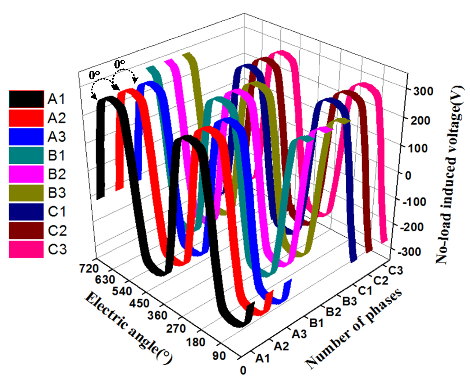
The star of slots for the 3*3-phase PM energy storage motor is illustrated in Figure 2. It should be noted that there is no electrical and magnetic connection between the six winding segments. Figure 3 shows the no-load back electromotive force of 3*3-phase PM energy storage motor. Figure 4 shows torque curve of 3*3-phase PM energy storage motor. The characteristics of 6*3-phase PM energy storage motor are as follow [10]:
(1) The no-load back electromotive force (EMF) of 3*3-phase PM energy storage motor coincides completely with sinusoidal waveform. In addition, the volt-seconds characteristic of any two voltage source inverters (VSIs) should be the same in any sub-cycle.
(2) It can be known from Figure 5 that the three-phase motor unit 1, 2 or 3 of 3*3-phase PM energy storage motor has the same electromagnetic torque. Therefore, the output electromagnetic torque of 3*3-phase PM energy storage motor is the sum of the output electromagnetic torque of each three-phase PMSM unit, which satisfies the superposition characteristic of the output torque.

2.2. Mathematical Model of N*3-phase PM Energy Storage Motor

According to the characteristics analysis of the N*3-phase PM energy storage motor, the d-and q-axis voltage equations of N*3-phase PM energy storage motor can be obtained as follows [10,16]:
{ d i d j d t = R o L o i d j + ω e i q j + 1 L o u d j d i q j d t = R o L o i q j ω e i d j ψ r o L o ω e + 1 L o u q j
where j stands for any unit of the motor, i d j and i q j are the d-and q-axis currents, respectively; R o and L o are the stator resistance and stator inductance, respectively; ω e is the electrical rotor speed, ψ r o is the flux linkage of permanent magnets; u d j and u q j represent the d- and q-axis voltages of the jth winding, respectively.
The N*3-phase PM energy storage motor is composed of three-phase SPMSM units with identical characteristics. Therefore, the stator resistance and stator inductance of each three-phase SPMSM unit are equal. The electromagnetic torque produced by each three-phase SPMSM unit is equal. The output electromagnetic torque of N*3-phase PM energy storage motor is the sum of the electromagnetic torque produced by each three-phase SPMSM unit. The electromagnetic torque produced by the N*3-phase PM energy storage motor can be expressed as follows [16]:
T e = 3 n p 2 j = 1 N ( ψ r o i q j )
The mechanical dynamic model of N*3-phase PM energy storage motor can be described as follows:
T e T L = J p d ω e d t
where n p is the number of pole pairs, J is the moment of inertia; T e and T L are the electromagnetic torque and load torque of the N*3-phase PM energy storage motor, respectively.

3. Topological Structure of N*3-phase PM Energy Storage Motor Drive System

With the increasing load power of high-speed railway electric multiple units (EMUs), the total capacity of converter is also increasing. The capacity of single power electronics converter module cannot meet the demand of high-speed railway EMUs system. Thus, the multi-module parallel power electronics converter energy storage system based on N*3-phase PM energy storage motor is proposed in this paper. Due to the limitation of flywheel safety and space of high-speed railway EMUs, the application of flywheel energy storage technology in rail transit is limited to the ground. The topological structure of N*3-phase PM energy storage motor system for ground rail transit is illustrated in Figure 5. The topology consists of a back-to-back converter, and the flywheel is connected with the converter through the N*3-phase PM energy storage motor to realize energy transfer.
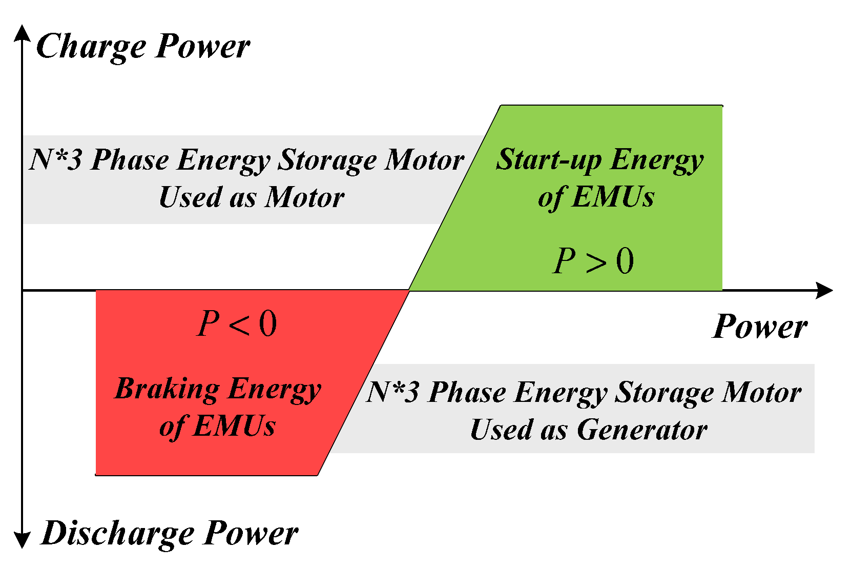
The N*3-phase PM energy storage motor system can be divided into charging and discharging working states, as shown in Figure 6. When the high-speed railway EMUs accelerates and leaving the station, the flywheel energy storage system is charged state. N*3-phase PM energy storage motor is used as motor (i.e., power of N*3-phase PM energy storage motor P > 0 ). When the high-speed railway EMUs decelerates and brakes into the station, the flywheel energy storage system is discharged state. The N*3-phase PM energy storage motor is used as generator (i.e., power of N*3-phase PM energy storage motor P < 0 ). Through the above analysis, the charging and discharging control of N*3-phase PM energy storage motor system is essentially the power control of N*3-phase PM energy storage motor.

4. Predictive Power Control of Novel N*3-phase PM Energy Storage Motor

4.1. Drive System Structure of N*3-phase PM Energy Storage Motor

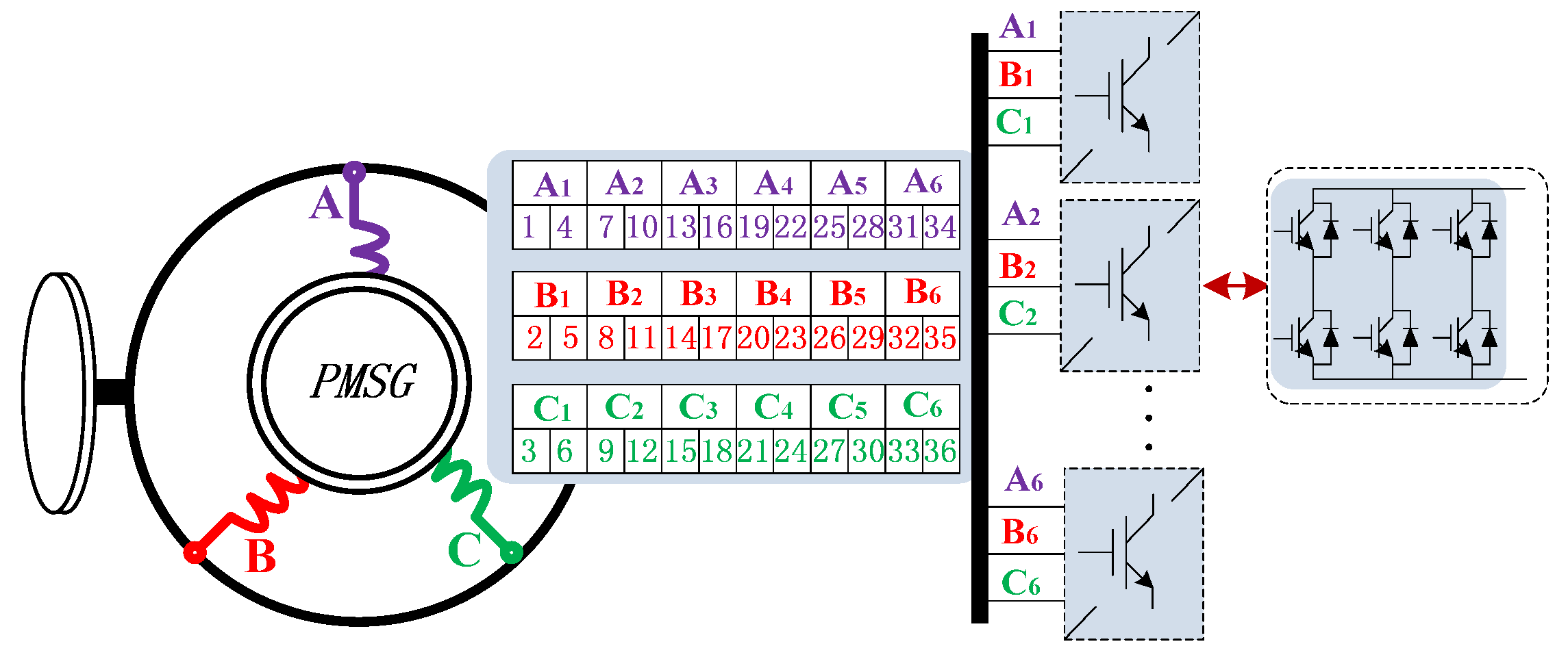
Taking 6*3-phase PM energy storage motor as an example, the 6*3-phase PM energy storage motor is driven by six drive units to obtain required power. The 18 stator winding wiring of 6*3-phase PM energy storage motor are connected with six voltage source inverters (VSI) in parallel, as shown in Figure 7. It can be seen from Figure 7 that each group of stator windings is excited independently with three phase symmetrical voltage generated by a voltage source inverter. The volt-seconds characteristic of any two VSIs are the same in any sub-cycle. The mathematical model and characteristic of each motor units is identical with a regular PMSM, and all the characteristics of each motor units are repetitive. The control of a voltage source inverter can be analogous to that of a conventional inverter. In this paper, a novel predictive direct power control method is proposed for the N*3-phase PM energy storage motor.

4.2. Predictive Power Control of Novel N*3-phase PM Energy Storage Motor

The PPC method is a discrete control algorithm based on the precise mathematical model of N*3-phase PM energy storage motor. It is necessary to discretize the mathematical model of the N*3-phase PM energy storage motor and then design the predictive power controller.
The general solution of voltage equations of N*3-phase PM energy storage motor can be expressed as follows:
x j ( t ) = e A ( t t o ) x j ( t o ) + t o t e A ( t τ ) ( B u j ( τ ) + D ) d τ
where x j ( t ) = [ i d j i q j ] , u j ( t ) = [ u d j u q j ] , A ( t ) = [ R o L o ω e ω e R o L o ] , B = [ 1 L o 0 0 1 L o ] , D = [ 0 ω e L o ψ r o ] .
Let t o = k T s , t o = ( k + 1 ) T s , T s is the sampling period. When the sampling period is short enough, we can get:
{ e R o T s L o 1 R o T s L o e R o T s L o 1 R o T s L o cos ( ω e T s ) 1 sin ( ω e T s ) ω e T s
Thus, according to (1), the discrete state equation of the N*3-phase PM energy storage motor can be obtained as follows:
{ u d j ( k ) = L o T s i d j ( k + 1 ) + ( R o L o T s ) i d j ( k ) L o ω e ( k ) i q j ( k ) u q j ( k ) = L o T s i q j ( k + 1 ) + ( R o L o T s ) i q j ( k ) + L o ω e ( k ) i d j ( k ) + ψ r o ω e ( k )
The power discrete expression of N*3-phase PM energy storage motor can be expressed as:
P ( k ) = T e ( k ) ω e ( k )
According to (7), it is known that the purpose of PPC method is to control the motor’s torque. To minimize the absolute error between the predicted stator flux and torque values with its reference values, the cost function is defined as:
g = k ψ | ψ s r e f ψ s ( k + 1 ) | + | T e r e f T e ( k + 1 ) |
where k ψ is a weighting factor; T e r e f and ψ s r e f are the torque reference value and flux linkage reference value, respectively; T e ( k + 1 ) and ψ s ( k + 1 ) are the predicted torque value and predicted flux linkage value, respectively.
If the PPC sampling period T s is short enough, the discrete form of N*3-phase PM energy storage motor can be modeled by the first-order Taylor expansion. The torque and stator flux prediction equation of N*3-phase PM energy storage motor can be expressed as:
{ ψ s ( k + 1 ) = ψ d j 2 ( k + 1 ) + ψ q j 2 ( k + 1 ) T e ( k + 1 ) = 3 n p 2 j = 1 N [ ψ r o i q j ( k + 1 ) ]
where ψ d j ( k + 1 ) and ψ q j ( k + 1 ) are the d-and q-axis stator flux components, respectively; i q j ( k + 1 ) is the q-axis current response.
According to (2) and (6), the torque prediction equation of N*3-phase PM energy storage motor can be expressed as follows:
T e ( k + 1 ) = 3 N n p 2 [ ψ r o i q j ( k + 1 ) ]
where
i q j ( k + 1 ) = 1 L o T s u q j ( k ) ( R o L o T s 1 ) i q j ( k ) T s ω e ( k ) i d j ( k ) 1 L o T s ψ r o ω e ( k )
According to (6), the stator flux prediction equation of N*3-phase PM energy storage motor can be expressed as follows:
{ ψ d j ( k + 1 ) = T s u d j ( k ) + ( 1 R o L o T s ) ψ d j ( k ) + T s ω e ( k ) ψ q j ( k ) + R o L o ψ r o T s ψ q j ( k + 1 ) = T s u q j ( k ) + ( 1 R o L o T s ) ψ q j ( k ) T s ω e ( k ) ψ d j ( k )
where
{ ψ d j ( k ) = L o i d j ( k ) + ψ r o ψ q j ( k ) = L o i q j ( k )
According to (7), the torque reference value can be obtained as follows:
T e r e f = P r e f ω e ( k )
Using the maximum torque per ampere (MTPA) control strategy, the relationship between stator flux reference and torque reference can be expressed as follows:
ψ s r e f = ψ d 2 + ψ q 2 = ( ψ r o ) 2 + ( L o · T e r e f 3 N n p 2 ψ r o ) 2
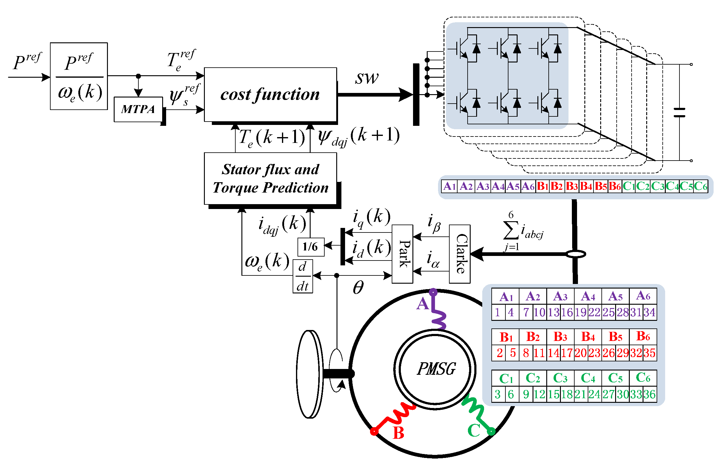
The structural diagram of the 6*3-phase PM energy storage motor system with PPC strategy is shown in Figure 8. According to Figure 8, the operating principle of the 6*3-phase PM energy storage motor drive system is as follows: According to (10) and (12), the predicted values of stator flux and torque at the ( k + 1 ) T s moment can be calculated. Then, the switching signal of the VSI can be obtained by substituting the predicted values and the response values into the cost function (8). Because six VSIs are connected with six sets of windings of 6*3-phase PM energy storage motor, controlling one of them can realize the control of the whole 6*3-phase PM energy storage motor system. The proposed PPC strategy is used to obtain the excellent torque and stator flux control performance. The proposed PPC strategy can effectively eliminate the steady errors of the stator flux and torque while obtaining lower stator flux and torque ripple.

5. Simulations

Taking 6*3-phase PM energy storage motor as an example to verify PPC algorithm. The 6*3-phase PM energy storage motor drive system is established by using the MATLAB/Simulink. During the charging and discharging process of 6*3-phase PM energy storage motor, some simulation results are given to verify the effectiveness of the proposed PPC strategy. The main parameters of 6*3-phase PM energy storage motor used in the simulation are given in Table 1. The simulation analysis of charge and discharge state of 6*3-phase PM energy storage motor is given in Figure 9, Figure 10, Figure 11, Figure 12, Figure 13, Figure 14, Figure 15, Figure 16, Figure 17 and Figure 18.

5.1. Control Performance of N*3-phase PM Energy Storage Motor under the Charge State

To verify the operation performance of the 6*3-phase PM energy storage motor under the charge state, the power reference is set as follows:
{ P r e f = 1.6 × 10 5 t + 0.8 × 10 5 P r e f = 1.6 × 10 5 0 t 0.5 s 0.5 s t 1 s
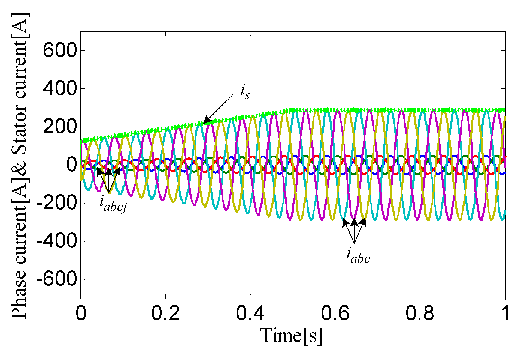
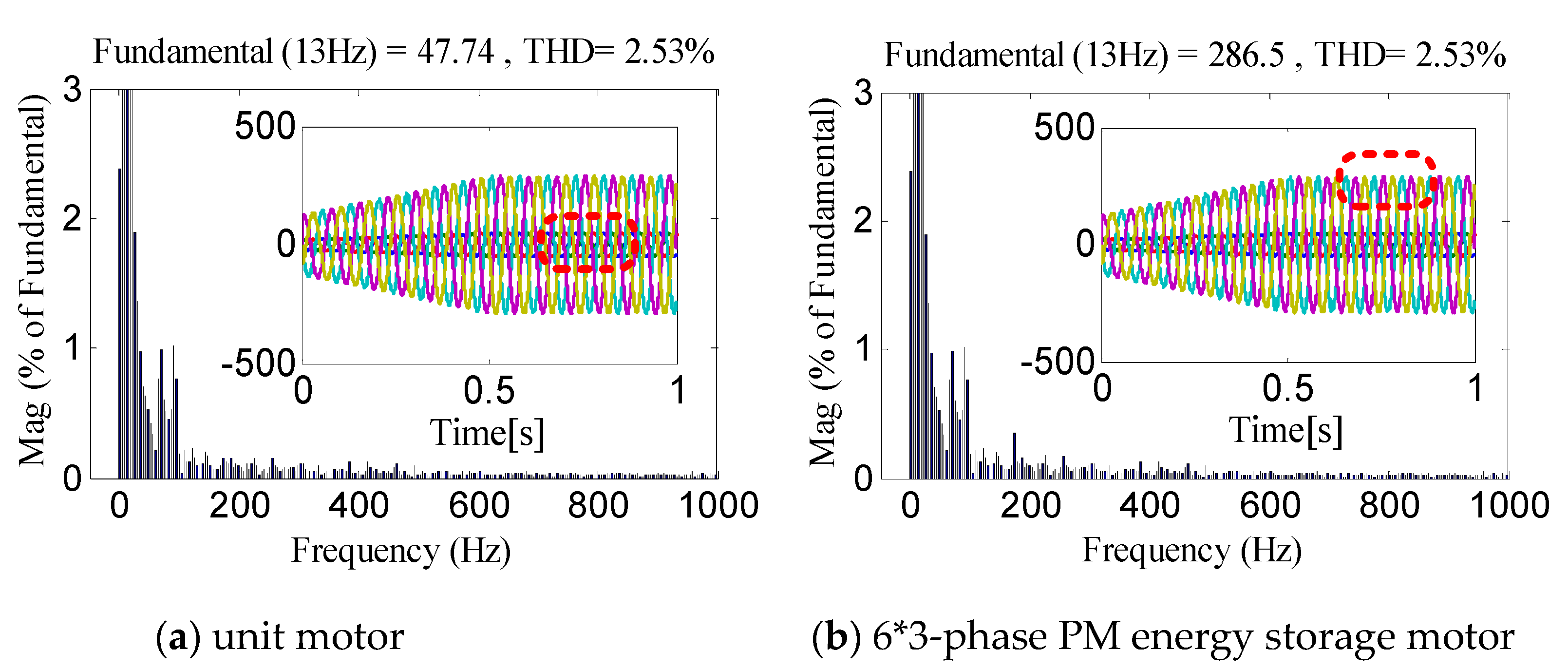
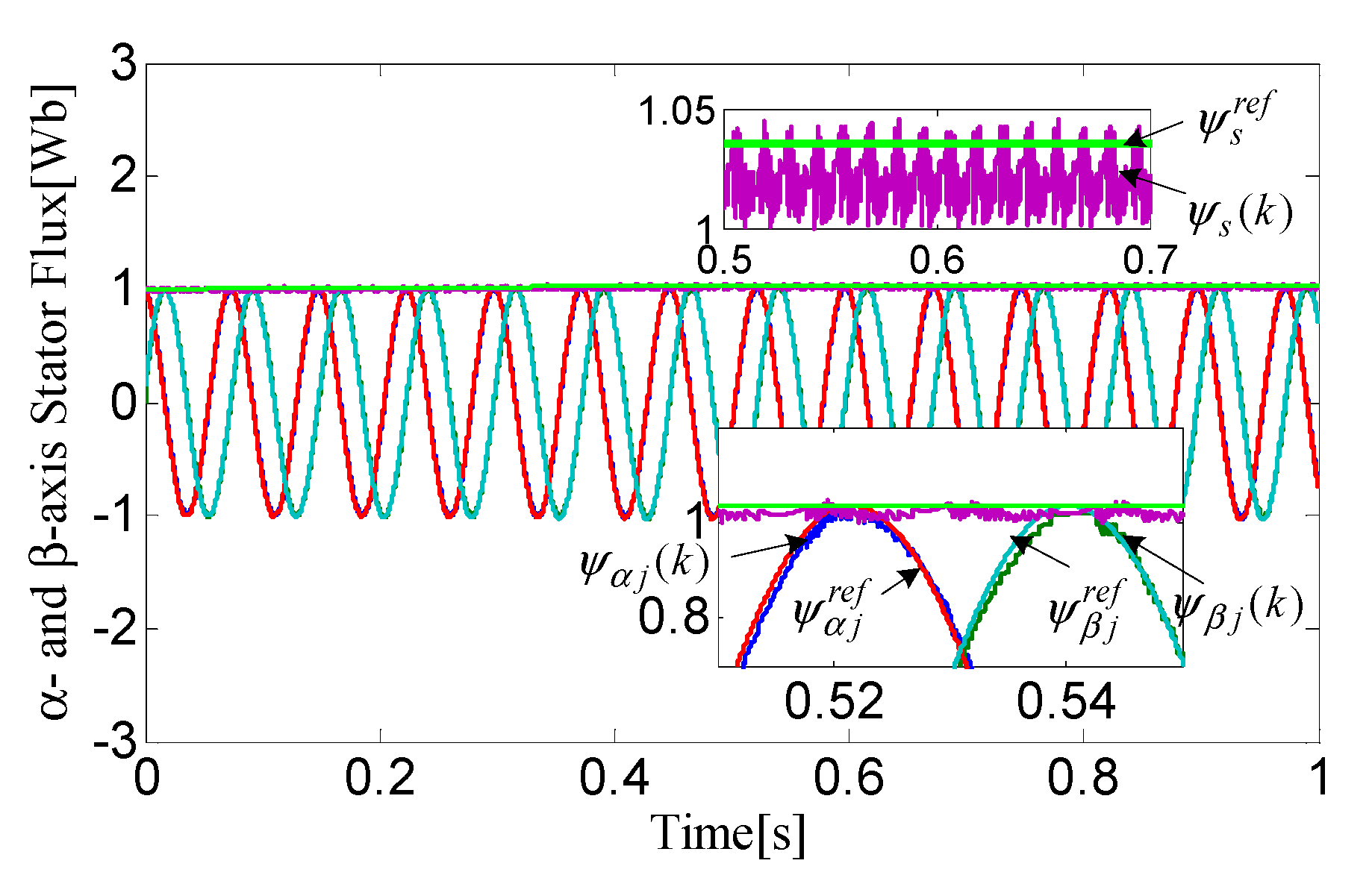
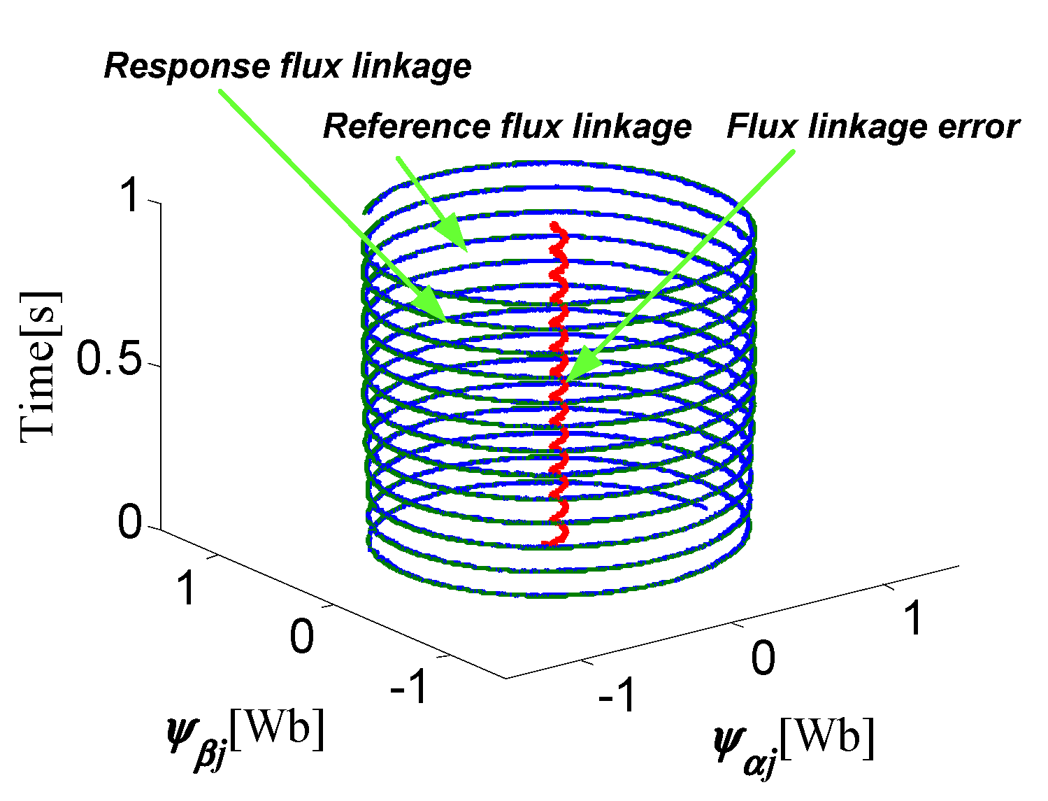
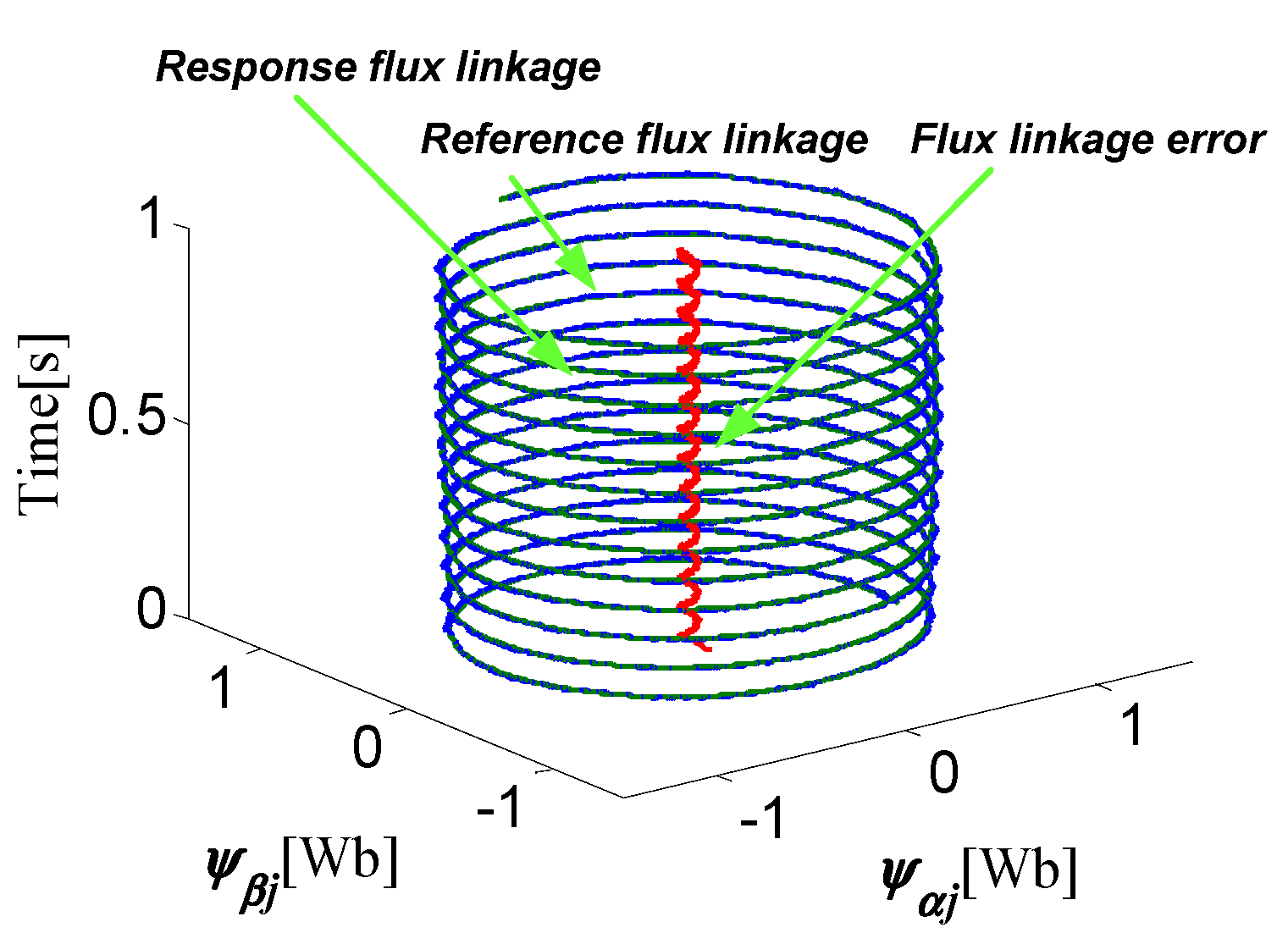
Simulation results of 6*3-phase PM energy storage motor under the charge state are shown in Figure 9, Figure 10, Figure 11, Figure 12 and Figure 13. Simulation results of the torque and phase current under the charge state are illustrated in Figure 9. From Figure 9, it can be seen that the peak-to-peak torque ripple is only ±200 N·m for 6*3-phase PM energy storage motor under the charge state. Furthermore, the stator current of 6*3-phase PM energy storage motor can keep a perfect sinusoidal waveform. The phase current of the 6*3-phase PM energy storage motor and unit motor under the charge state is given in Figure 10. From 0 to 0.5 s, the stator current increases with the increase of the power reference value. After 0.5 s, the stator current is stable at 287A. Figure 11 shows the stator current frequency spectra of the 6*3-phase PM energy storage motor and unit motor under the charge state. From Figure 11a,b, it can be known that the stator current fundamental value of the unit motor is about 47.74A, while that of the 6*3-phase PM energy storage motor is about 286.5A, which is about six times. The torque superposition characteristic of 6*3-phase PM energy storage motor is verified. In addition, it can be seen that the THD of 6*3-phase PM energy storage motor and unit motor is 2.53%, both lower than 5%. Figure 12 shows the α-β stator flux linkage of the 6*3-phase PM energy storage motor under the charge state. The α-β stator flux linkage response value and reference value of the 6*3-phase PM energy storage motor are shown in Figure 12, where it can be observed that the response value of α-β stator flux linkage can accurately track the reference value. It also needs to be noted that the α-β stator flux linkage fluctuation value of 6*3-phase PM energy storage motor is only ±0.05 Wb, and the α-β stator flux linkage track errors is about 0.02 Wb. Figure 13 shows the three-dimensional rotor flux trajectories of the 6*3-phase PM energy storage motor under the charge state. It is known that there is a smaller α-β stator flux linkage track error between the stator flux linkage reference value and the response value by using the proposed PPC strategy, which are shown clearly in Figure 13. In summary, when the proposed PPC strategy in this paper is used, the 6*3-phase PM energy storage motor can achieve satisfactory control performance under the charge state.

5.2. Control Performance of N*3-phase PM Energy Storage Motor under the Discharge State

To verify the operation performance of the 6*3-phase PM energy storage motor under the discharge state, the power reference is set as follows:
{ P r e f = 1.6 × 10 5 t 0.8 × 10 5 P r e f = 1.6 × 10 5 0 t 0.5 s 0.5 s t 1 s
Simulation results of 6*3-phase PM energy storage motor under the discharge state are shown in Figure 14, Figure 15, Figure 16, Figure 17 and Figure 18. The torque and phase current of 6*3-phase PM energy storage motor under the discharge state is given in Figure 14. From 0 to 0.5 s, the torque response value decreases with the decrease of the power reference value. After 0.5 s, the torque response value of 6*3-phase PM energy storage motor is stable at −2100 N·m, and the peak-to-peak torque ripple is also only ±200 N·m. The phase current of the 6*3-phase PM energy storage motor and unit motor under the discharge state is illustrated in Figure 15. From Figure 15, it can be known that the phase currents of 6*3-phase PM energy storage motor and unit motor keeps a good sinusoidal waveform. In addition, the phase current amplitude of 6*3-phase PM energy storage motor is about six times of that of unit motor, which verifies the torque superposition characteristic of 6*3-phase PM energy storage motor.
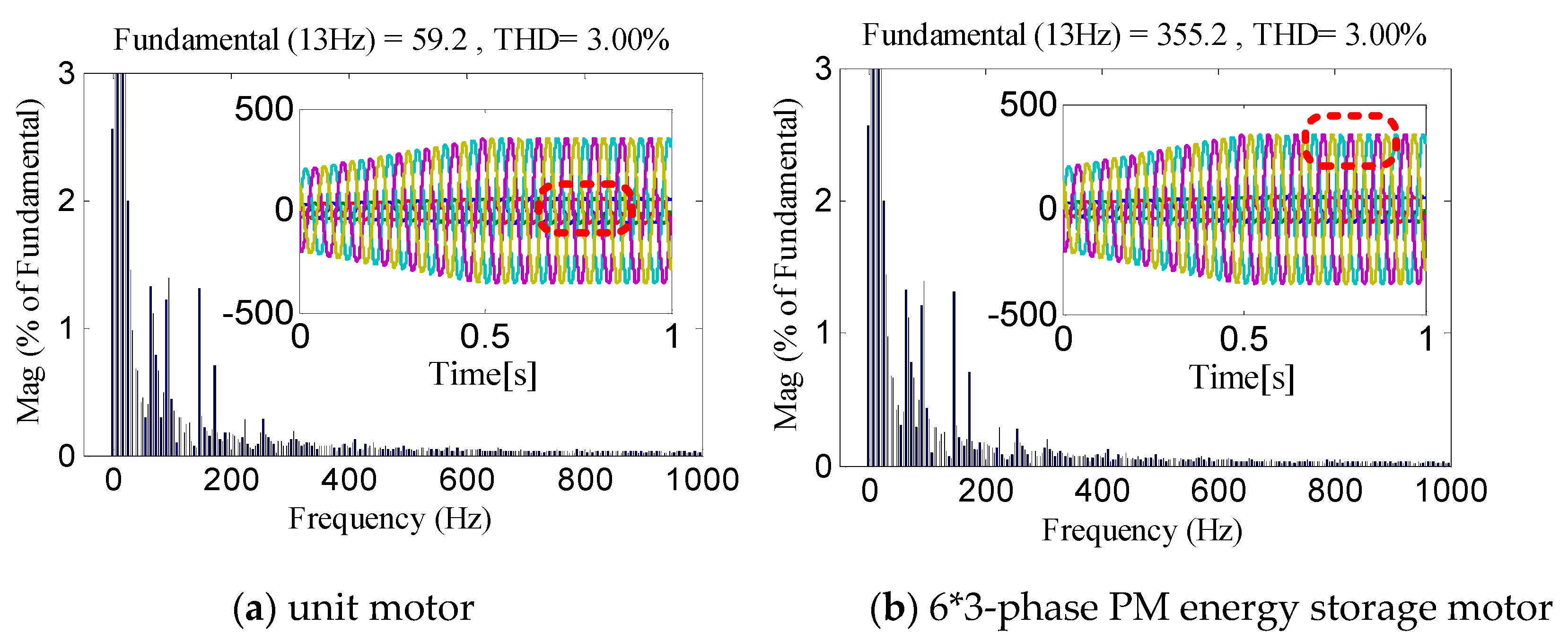
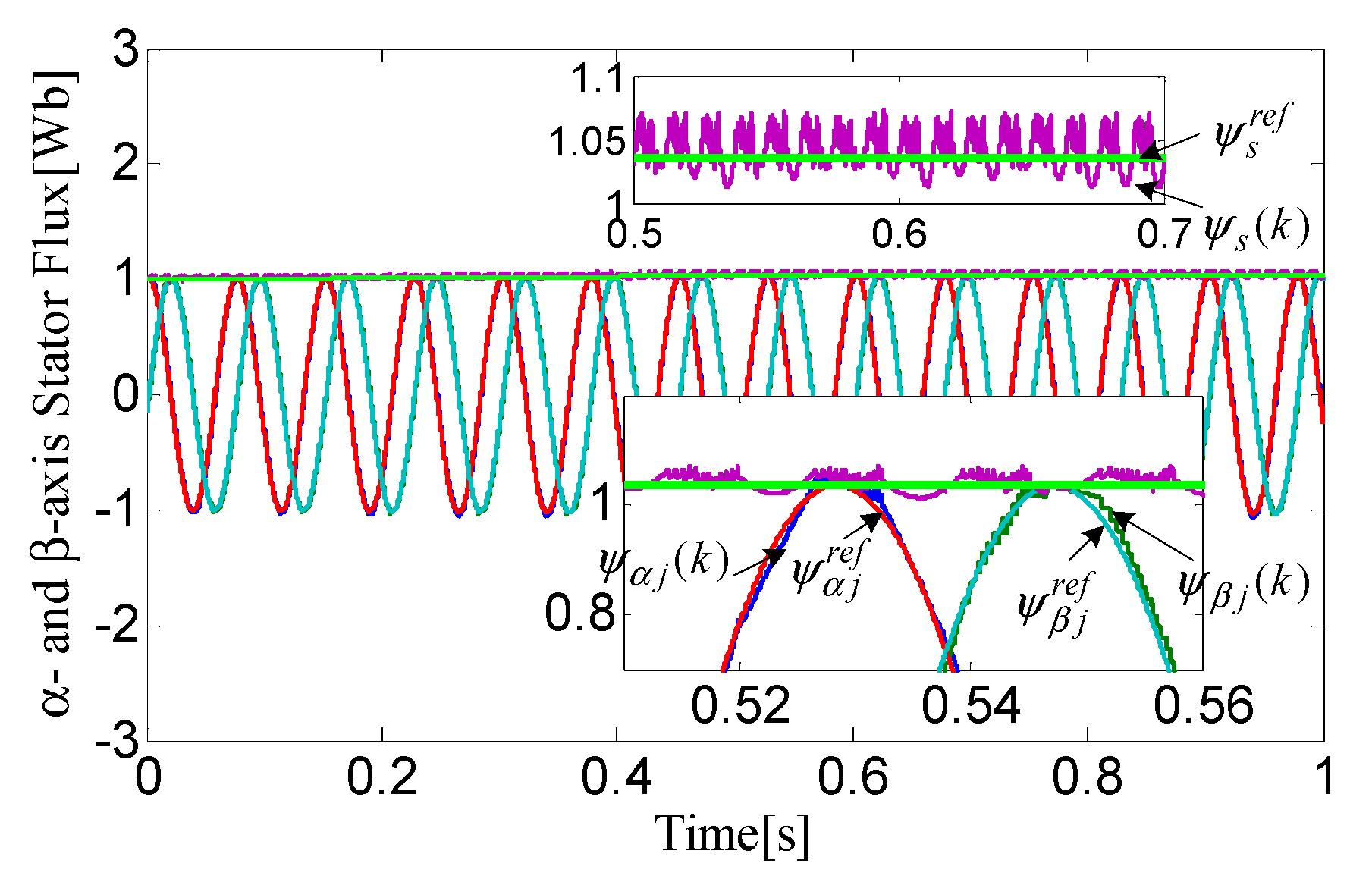
Figure 16 shows that the stator current frequency spectra of the 6*3-phase PM energy storage motor and unit motor under the discharge state. From Figure 16a, it can be known that the stator current fundamental value and the THD of unit motor are 59.2 A and 3.00%, respectively. The stator current fundamental value and the THD of 6*3-phase PM energy storage motor are respectively 59.2 A and 3.00%, which are shown clearly in Figure 16b. Figure 18 shows that the α-β stator flux linkage of the 6*3-phase PM energy storage motor under the discharge state. From Figure 17, it can be observed that the fluctuation value and tracking error of α-β stator flux linkage are ±0.03 Wb and 0.01 Wb, respectively. The response value of α-β stator flux linkage can accurately track the reference value, which are shown clearly in Figure 17. Figure 18 shows the three-dimensional rotor flux trajectories of the 6*3-phase PM energy storage motor under the discharge state. Under the discharge state, the flux linkage error between the flux linkage response value and its reference is very small by adopting the proposed PPC strategy, which are shown clearly in Figure 18. In summary, the proposed PPC strategy can make the 6*3-phase PM energy storage motor to achieve lower torque ripple and smaller values of THD of stator winding currents under discharge state.

6. Experimental Results

In this paper, the PPC method of N*3-phase PM energy storage motor is verified by using the RT-Lab hardware-in-the-loop simulation (HILS) platform. Taking 6*3-phase PM energy storage motor as an example, the feasibility and effectively of proposed PPC algorithm is verified on the RT-Lab HILS platform. The parameters of RT-Lab HILS platform in RT-Lab HILS platform are consistent with those of simulation. In the case of charge state and discharge state of 6*3-phase PM energy storage motor, the experimental results of the proposed PPC algorithm are shown in Figure 19, Figure 20, Figure 21, Figure 22, Figure 23 and Figure 24.
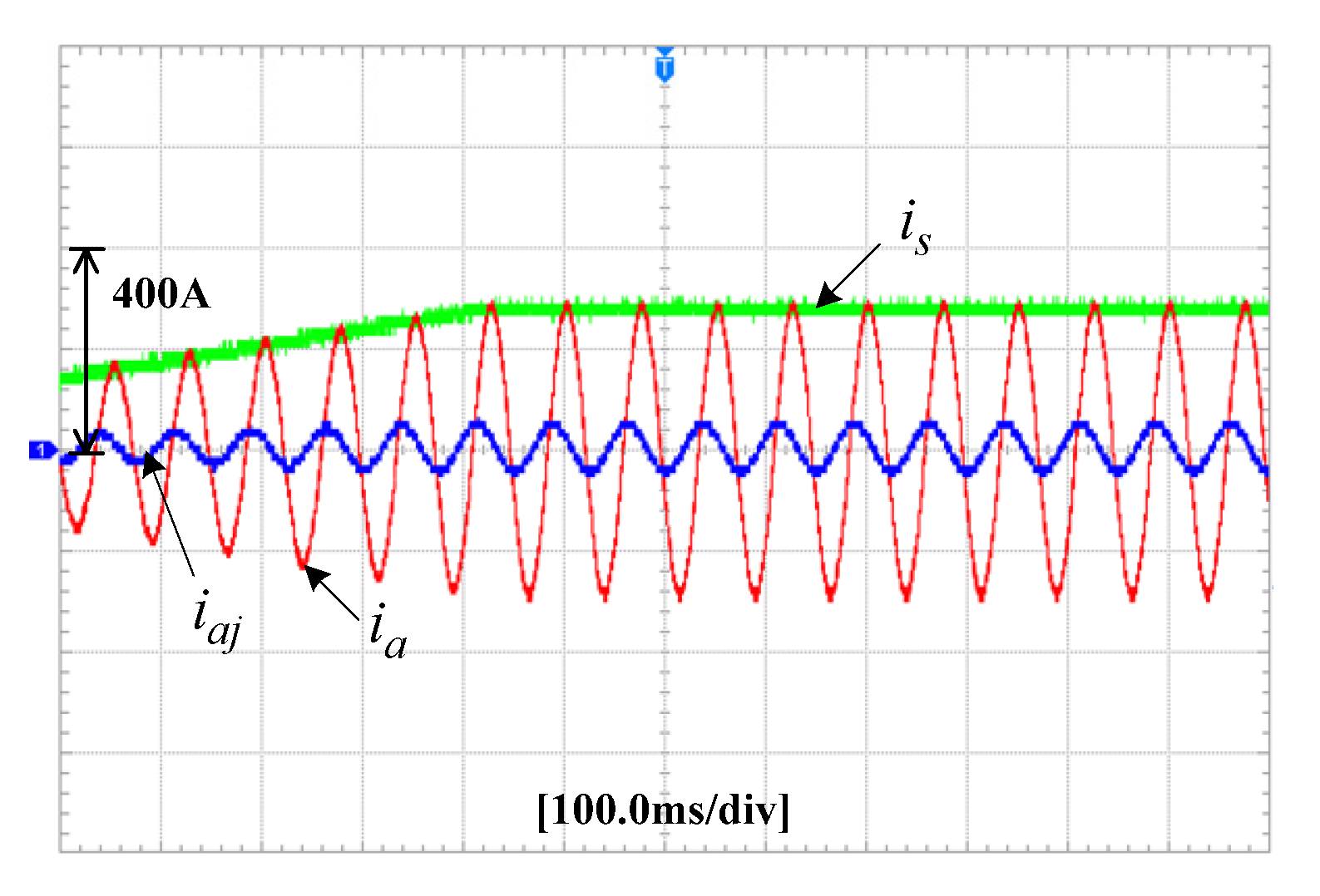
In Figure 19, the experimental results of the torque and phase current of the 6*3-phase PM energy storage motor under the charge state are shown. The torque and phase current of 6*3-phase PM energy storage motor are about 1700 N·m and 290 A under the charge state, respectively. The experimental results show that the proposed PPC method can achieve perfect torque and stator current control performance under the charge state. The experimental results of the phase current of the 6*3-phase PM energy storage motor and the unit motor under the charge state are illustrated in Figure 20. The phase current of 6*3-phase PM energy storage motor is 6 times of that of unit motor under the charge state, about 290 A. The reason is that the torque of 6*3-phase PM energy storage motor satisfies the superposition characteristic. Figure 21 shows that the experimental results of the α-β stator flux linkage of the 6*3-phase PM energy storage motor under the charge state. The α-β stator flux linkage value of the 6*3-phase PM energy storage motor is about 1.03Wb. The experimental results show that the flux linkage predicted value of the 6*3-phase PM energy storage motor can accuracy track its reference value by using the PPC method. The experimental results in Figure 19, Figure 20 and Figure 21 show that the proposed PPC algorithm can achieve high-performance control of 6*3-phase PM energy storage motor under the charge state.
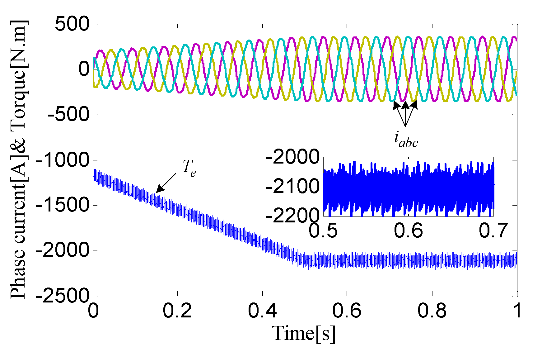
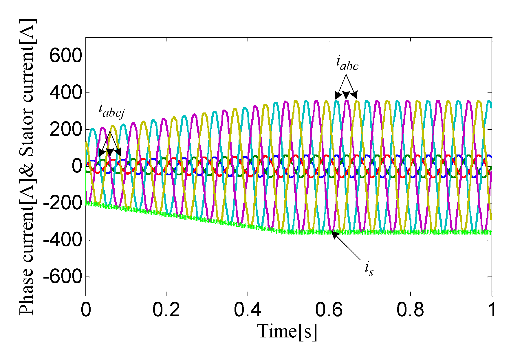
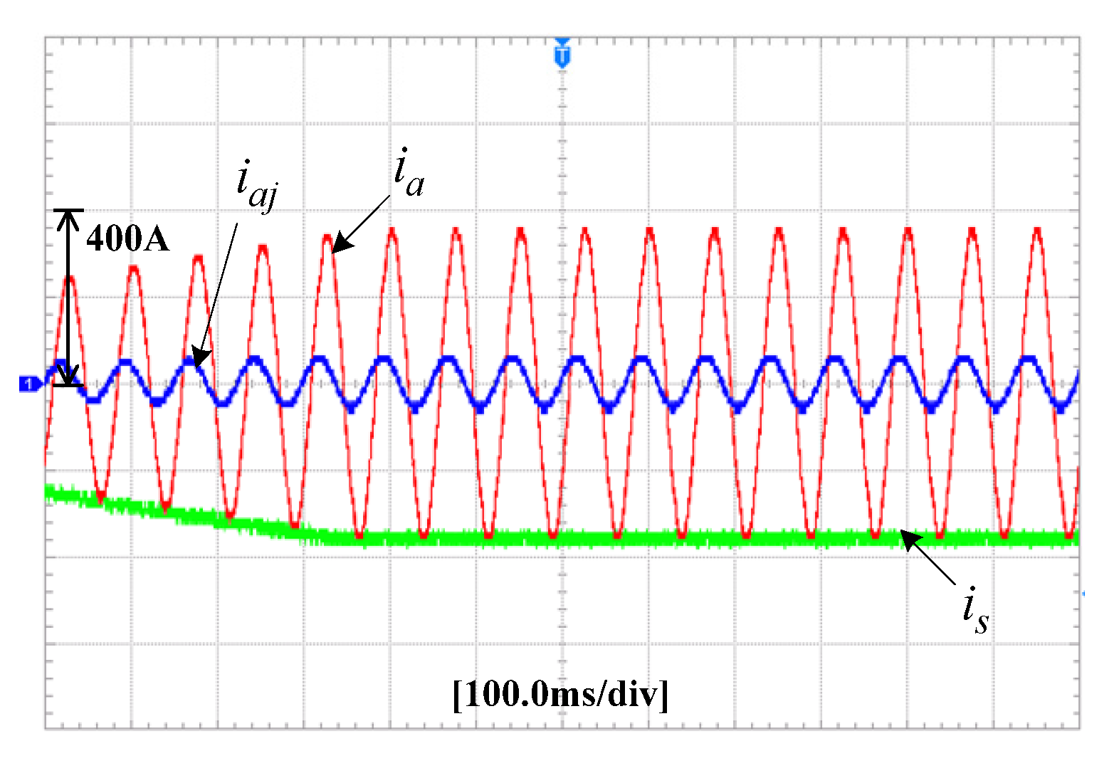
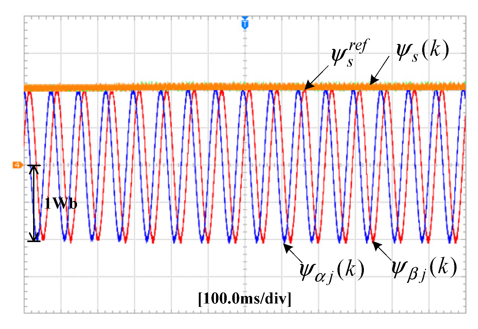
The experimental results of the torque and phase current of the 6*3-phase PM energy storage motor under the discharge state are shown in Figure 22. The torque and phase current of 6*3-phase PM energy storage motor are about−2100 N·m and 355 A under the discharge state, respectively. From Figure 22, it is known that the perfect torque and stator current control performance can be obtained by using the proposed PPC method. In Figure 23, the experimental results of the phase current of the 6*3-phase PM energy storage motor and the unit motor under the discharge state are illustrated. The experimental result shows that the phase current of 6*3-phase PM energy storage motor is also six times of that of unit motor under the discharge state. The phase current of 6*3-phase PM energy storage motor is 6 times of that of unit motor under the discharge state, about 355A. Furthermore, the perfect sinusoidal waveform of 6*3-phase PM energy storage motor can be achieved under the discharge state, which are shown in Figure 23. The experimental results of the α-β stator flux linkage of the 6*3-phase PM energy storage motor under the charge state are shown in Figure 24. The α-β stator flux linkage value of the 6*3-phase PM energy storage motor is about 1.03 Wb. The flux linkage predicted value of the 6*3-phase PM energy storage motor can accuracy track its reference value under the discharge state, which are shown in Figure 24. From Figure 22, Figure 23 and Figure 24, it can be known that the 6*3-phase PM energy storage motor can obtain perfect performance control by adopting the proposed PPC method.

7. Conclusions

This paper started from analyzing the output characteristics of the N*3-phase PM energy storage motor drive, based on which the PPC method was developed to obtain the performance of lower torque ripple, smaller values of THD of stator winding currents under the charge state and discharge state. For the first time, the proposed PPC algorithm is used to control the N*3-phase PM energy storage motor in this paper. The designed N*3-phase PM energy storage motor has the advantages of simple structure, strong robustness, and high power density. The multi-module parallel power electronics converter energy storage system based on N*3-phase PM energy storage motor is designed to meet the demand of high-speed railway EMUs system. Moreover, the novel PPC strategy is proposed to eliminate the steady errors of the torque and stator flux while achieving lower stator flux and torque ripple. No matter the N*3-phase PM energy storage motor is operating in the state of charge or discharge, the proposed PPC method can achieve perfect control performance. Simulation and experimental results verify that the proposed PPC method operates well in the case of charge state and discharge state while obtaining the lower torque/stator flux ripple, smaller values of THD of stator winding currents.

Author Contributions

Conceived the theory and built the model, W.Z.; performed the simulations and experiments and analyzed the data, W.Z., G.W., D.L. and J.Z.; wrote the paper, W.Z., G.W. and Z.R.; funding acquisition, W.Z. and G.W. All authors have read and agreed to the published version of the manuscript.

Funding

This research was supported in part by the Natural Science Foundation of Hunan Province under Grant 2018JJ3562, in part by the Youth Project of Education Department of Hunan Province under Grant 18B411 and in part by the Hunan Provincial Innovation Key Foundation for Postgraduate under Grant CX20190261.

Conflicts of Interest

The authors declare no conflict of interest.

References

  1. Huang, Y.; Yang, L.; Tang, T.; Cao, F.; Gao, Z. Saving energy and improving service quality: Bicriteria train scheduling in urban rail transit systems. IEEE Trans. Intell. Transp. Syst. 2016, 17, 3364–3379. [Google Scholar] [CrossRef]
  2. Sun, H.; Wu, J.; Ma, H.; Yang, X.; Gao, Z. A bi-objective timetable optimization model for urban rail transit based on the time-dependent passenger volume. IEEE Trans. Intell. Transp. Syst. 2018, 20, 604–615. [Google Scholar] [CrossRef]
  3. Faraji, F.; Majazi, A.; Al-Haddad, K. A comprehensive review of flywheel energy storage system technology. Renew. Sustain. Energy Rev. 2017, 67, 477–490. [Google Scholar]
  4. Zhang, X.; Yang, J. A DC-link voltage fast control strategy for high-speed PMSM/G in flywheel energy storage system. IEEE Trans. Ind. Appl. 2017, 54, 1671–1679. [Google Scholar] [CrossRef]
  5. Gengji, W.; Ping, W. Rotor loss analysis of PMSM in flywheel energy storage system as uninterruptable power supply. IEEE Trans. Appl. Supercond. 2016, 26, 1–5. [Google Scholar] [CrossRef]
  6. Huang, W.; Hua, W.; Chen, F.; Hu, M.; Zhu, J. Model predictive torque control with SVM for five-phase PMSM under open-circuit fault condition. IEEE Trans. Power Electron. 2019, 35, 5531–5540. [Google Scholar] [CrossRef]
  7. Wang, W.; Zhang, J.; Cheng, M.; Li, S. Fault-tolerant control of dual three-phase permanent-magnet synchronous machine drives under open-phase faults. IEEE Trans. Power Electron. 2016, 32, 2052–2063. [Google Scholar] [CrossRef]
  8. Huang, W.; Hua, W.; Chen, F.; Zhu, J. Enhanced model predictive torque control of fault-tolerant five-phase permanent magnet synchronous motor with harmonic restraint and voltage pre-selection. IEEE Trans. Ind. Electron. 2019. [Google Scholar] [CrossRef]
  9. Zhou, Y.; Lin, X.; Cheng, M. A fault-tolerant direct torque control for six-phase permanent magnet synchronous motor with arbitrary two opened phases based on modified variables. IEEE Trans. Energy Convers. 2015, 31, 549–556. [Google Scholar] [CrossRef]
  10. Rao, Z.; Zhang, Z.; Huang, S.; Long, Z.; Wu, G. Characteristics and current harmonic control of N* three-phase PMSG for HVDC transmission Based on MMC. Energies 2020, 13, 178. [Google Scholar] [CrossRef] [Green Version]
  11. Demir, Y.; Aydin, M. A novel dual three-phase permanent magnet synchronous motor with asymmetric stator winding. IEEE Trans. Magn. 2016, 52, 1–5. [Google Scholar] [CrossRef]
  12. Demir, Y.; Aydin, M. A novel asymmetric and unconventional stator winding configuration and placement for a dual three-phase surface PM motor. IEEE Trans. Magn. 2017, 53, 1–5. [Google Scholar] [CrossRef]
  13. Barcaro, M.; Bianchi, N.; Magnussen, F. Analysis and tests of a dual three-phase 12-slot 10-pole permanent-magnet motor. IEEE Trans. Ind. Appl. 2010, 46, 2355–2362. [Google Scholar] [CrossRef]
  14. Luise, F.; Pieri, S.; Mezzarobba, M.; Tessarolo, A. Regenerative testing of a concentrated-winding permanent-magnet synchronous machine for offshore wind generation—Part I: Test concept and analysis. IEEE Trans. Ind. Appl. 2012, 48, 1779–1790. [Google Scholar] [CrossRef]
  15. Luise, F.; Pieri, S.; Mezzarobba, M.; Tessarolo, A. Regenerative testing of a concentrated-winding permanent-magnet synchronous machine for offshore wind generation—Part II: Test implementation and results. IEEE Trans. Ind. Appl. 2012, 48, 1791–1796. [Google Scholar] [CrossRef]
  16. Onsal, M.; Demir, Y.; Aydin, M. A new nine-phase permanent magnet synchronous motor with consequent pole rotor for high-power traction applications. IEEE Trans. Magn. 2017, 53, 1–6. [Google Scholar] [CrossRef]
  17. Chung, S.U.; Moon, S.H.; Kim, D.J.; Kim, J.M. Development of a 20-pole–24-slot SPMSM with consequent pole rotor for in-wheel direct drive. IEEE Trans. Ind. Electron. 2015, 63, 302–309. [Google Scholar] [CrossRef]
  18. Jung, E.; Yoo, H.; Sul, S.K.; Choi, H.S.; Choi, Y.Y. A nine-phase permanent-magnet motor drive system for an ultrahigh-speed elevator. IEEE Trans. Ind. Appl. 2012, 48, 987–995. [Google Scholar] [CrossRef]
  19. Buja, G.S.; Kazmierkowski, M.P. Direct torque control of PWM inverter-fed AC motors—A survey. IEEE Trans. Ind. Electron. 2004, 51, 744–757. [Google Scholar] [CrossRef]
  20. Xie, W.; Wang, X.; Wang, F.; Xu, W.; Kennel, R.M.; Gerling, D.; Lorenz, R.D. Finite-control-set model predictive torque control with a deadbeat solution for PMSM drives. IEEE Trans. Ind. Electron. 2015, 62, 5402–5410. [Google Scholar] [CrossRef]
  21. Xiang, Z.; Zhu, X.; Quan, L.; Du, Y. Multi-level design optimization and operation of a brushless double mechanical ports flux-switching permanent magnet motor. IEEE Trans. Ind. Electron. 2016, 62, 6042–6054. [Google Scholar] [CrossRef]
  22. Zhang, C.; Wu, G.; Rong, F.; Feng, J.; Jia, L.; He, J.; Huang, S. Robust fault-tolerant predictive current control for permanent magnet synchronous motors considering demagnetization fault. IEEE Trans. Ind. Electron. 2017, 65, 5324–5334. [Google Scholar] [CrossRef]
  23. Huang, S.; Wu, G.; Rong, F.; Zhang, C.; Huang, S.; Wu, Q. Novel predictive stator flux control techniques for PMSM drives. IEEE Trans. Power Electron. 2018, 34, 8916–8929. [Google Scholar] [CrossRef] [Green Version]
  24. Lyu, M.; Wu, G.; Luo, D.; Rong, F.; Huang, S. Robust nonlinear predictive current control techniques for PMSM. Energies 2019, 12, 443. [Google Scholar] [CrossRef] [Green Version]
  25. Hu, F.; Luo, D.; Luo, C.; Long, Z.; Wu, G. Cascaded robust fault-tolerant predictive control for PMSM drives. Energies 2018, 11, 3087. [Google Scholar] [CrossRef] [Green Version]
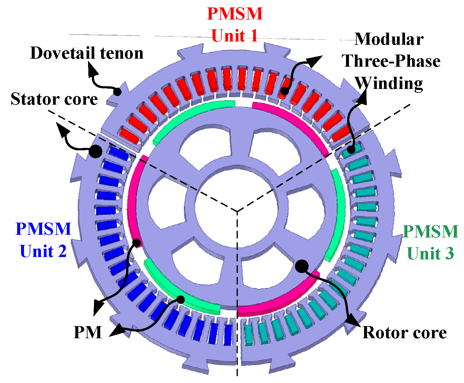
Figure 1. The structure diagram of the 3*3-phase PM energy storage motor.
Energies 13 01578 g001
Figure 2. The star of slots for 3*3-phase PM energy storage motor.
Energies 13 01578 g002
Figure 3. No-load back electromotive force of 3*3-phase PM energy storage motor.
Energies 13 01578 g003
Figure 4. Torque characteristics of 3*3-phase PM energy storage motor.
Energies 13 01578 g004
Figure 5. Topological structure of N*3-phase PM energy storage motor system for ground rail transit.
Energies 13 01578 g005
Figure 6. Energy recovery process of N*3-phase PM energy storage system.
Energies 13 01578 g006
Figure 7. Drive system structure of 6*3-phase PM energy storage motor drive.
Energies 13 01578 g007
Figure 8. Structural diagram of the 6*3-phase PM energy storage motor system with PPC strategy.
Energies 13 01578 g008
Figure 9. Simulation results of the torque and phase current under the charge state.
Energies 13 01578 g009
Figure 10. Phase current of the 6*3-phase PM energy storage motor and unit motor under the charge state.
Energies 13 01578 g010
Figure 11. Stator current frequency spectra of the 6*3-phase PM energy storage motor and unit motor under the charge state.
Energies 13 01578 g011
Figure 12. The α-β stator flux linkage of the 6*3-phase PM energy storage motor under the charge state.
Energies 13 01578 g012
Figure 13. The three-dimensional rotor flux trajectories of the 6*3-phase PM energy storage motor under the charge state.
Energies 13 01578 g013
Figure 14. Simulation results of the torque and phase current under the discharge state.
Energies 13 01578 g014
Figure 15. Phase current of the 6*3-phase PM energy storage motor and unit motor under the discharge state.
Energies 13 01578 g015
Figure 16. Stator current frequency spectra of the 6*3-phase PM energy storage motor and unit motor under the charge state.
Energies 13 01578 g016
Figure 17. The α-β stator flux linkage of the 6*3-phase PM energy storage motor under the discharge state.
Energies 13 01578 g017
Figure 18. The three-dimensional rotor flux trajectories of the 6*3-phase PM energy storage motor under the discharge state.
Energies 13 01578 g018
Figure 19. Experimental results of the torque and phase current under the charge state.
Energies 13 01578 g019
Figure 20. Experimental results of the phase current under the charge state.
Energies 13 01578 g020
Figure 21. Experimental results of the α-β stator flux linkage under the charge state.
Energies 13 01578 g021
Figure 22. Experimental results of the torque and phase current under the discharge state.
Energies 13 01578 g022
Figure 23. Experimental results of the phase current under the discharge state.
Energies 13 01578 g023
Figure 24. Experimental results of the α-β stator flux linkage under the discharge state.
Energies 13 01578 g024
Table 1. Phase PM energy storage motor.
ParametersValue
Stator phase resistance (Ro)0.026 Ω
Number of pole pairs (np)4
Inductances (Lo)5.572 mH
Flux linkage of PM (Ψro)0.992 Wb