Article

Analysis of Magnetic Field and Electromagnetic Performance of a New Hybrid Excitation Synchronous Motor with dual-V type Magnets

School of Transportation and Vehicle Engineering, Shandong University of Technology, Zibo 255049, China
*
Author to whom correspondence should be addressed.
Energies 2020, 13(6), 1501; https://doi.org/10.3390/en13061501
Submission received: 15 February 2020 / Revised: 14 March 2020 / Accepted: 17 March 2020 / Published: 22 March 2020

Abstract

:
Due to the increasing energy crisis and environmental pollution, the development of drive motors for new energy vehicles (NEVs) has become the focus of popular attention. To improve the sine of the air-gap flux density and flux regulation capacity of drive motors, a new hybrid excitation synchronous motor (HESM) has been proposed. The HESM adopts a salient pole rotor with built-in dual-V permanent magnets (PMs), non-arc pole shoes and excitation windings. The fundamental topology, operating principle and analytical model for a magnetic field are presented. In the analytical model, the rotor magnetomotive force (MMF) is derived based on the minimum reluctance principle, and the permeance function considering a non-uniform air-gap is calculated using the magnetic equivalent circuit (MEC) method. Besides, the electromagnetic performance including the air-gap magnetic field and flux regulation capacity is analyzed by the finite element method (FEM). The simulation results of the air-gap magnetic field are consistent with the analytical results. The experiment and simulation results of the performance show that the flux waveform is sinusoidal-shaped and the air-gap flux can be adjusted effectively by changing the excitation current. This study provides design methods and theoretical analysis references for this type of HESM.

Graphical Abstract

1. Introduction

With the rapid development of society, the exhaustion of fossil fuels and environmental pollution have become urgent problems. The development of new energy vehicles (NEVs) is one of the key approaches to solving these problems. Motor design is the key to the development of NEVs. Given this, various topologies of motors have been proposed. The permanent magnet synchronous motor (PMSM) has the advantage of high torque density, high power density, and high efficiency [1,2,3], but it is difficult to control the magnetic field [4]. The magnetic field of the electrical excitation motor (EEM) can be controlled easily, but the presence of the excitation winding increases the excitation loss, which leads to decreased efficiency. Based on the PMSM with added excitation windings, the hybrid excitation synchronous motor (HESM) with a controllable magnetic field has been proposed, and it has become the focus of increasing attention for scholars around the world [5,6,7].
In the past decades, many kinds of new HESM topologies have proposed and studied, which are mainly focused on the claw-pole type [8,9,10], the parallel type [11,12,13], rotor magnetic shunt type [14,15], and the combined rotor type [16], and most of them are used in generator systems. However, there are two main problems in these types of HSEMs. On the one hand, there is axial flux, which limits the axial length of the motor. On the other hand, there is an additional air-gap between the magnetic bridge and the rotor core, which reduces the efficiency of the motor, and the structure of the motor is more complex.
In the relatively few research works into HESMs without axial flux and additional air-gaps, a hybrid excitation double salient pole motor in which permanent magnets (PMs) and excitation windings are located on the stator is proposed [17,18]. The structure is simple and easily dissipates heat. However, when running as a motor, it causes a large torque ripple. In [19,20], PMs and excitation windings are integrated into one salient pole rotor, and the flux generated by excitation windings passes through PMs, which leads to the high reluctance of the magnetic path and low flux regulation capacity [21]. Based on the salient pole topology, a kind of HESM is researched in which PMs are fixed on the surface of the salient pole and do not cover the salient pole completely, in which the PM and electrical excitation flux are in parallel [22,23]. Since the PMs are “flat-type”, the capacity of magnetic gathering is weakened. An HESM with “spoke-type” PMs is presented in [24,25], in which the PMs are located between two adjacent rotor teeth with excitation coils. Since PMs are of the “spoke-type”, the HESM has high flux regulation capacity, but the top of the air-gap flux density waveform is too flat.
Aiming at solving the above-mentioned problems of the poor flux waveform quality and weak flux regulation ability of the existing motors, a new motor topology that considers both the magnetic flux distribution and flux regulation ability can be provided and studied. Furthermore, due to the complexity of the new motor structure, the existing analytical model cannot be used to calculate the magnetic field of the studied motor, so it is necessary to provide an analytical model for the new structure to calculate the magnetic field quickly and accurately.
In this paper, a new HESM with salient pole built-in dual-V PMs and non-arc pole shoes is proposed, in which the PMs are entirely devoted to enhancing the air-gap flux and avoiding dips of the middle field, and the role of the pole shoe is to improve the quality of field distribution, simplifying the manufacturing process. In this study, the operating principle, analytical model for magnetic field distribution, electromagnetic performance including the air-gap flux, back electromotive force (back-EMF) and the flux regulation of the motor is analyzed. According to the complicated rotor topology, the magnetomotive force (MMF) model with dual-layer combined PMs is built based on the principle of minimum reluctance, and the permeance function considering non-arc pole shoes and stator slots is derived by the magnetic equivalent circuit (MEC) method. To verify the validity of the analytical model, the calculation results of the magnetic field in the air-gap are compared with those of the finite element method (FEM). Finally, a prototype is manufactured and tested to verify the effectiveness of the topology design and theoretical analysis.

2. Machine Topology and Operating Principle

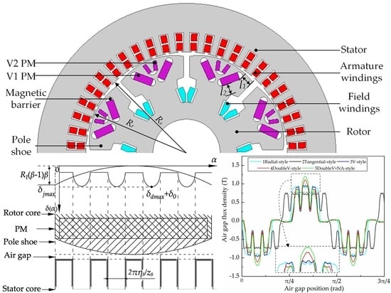
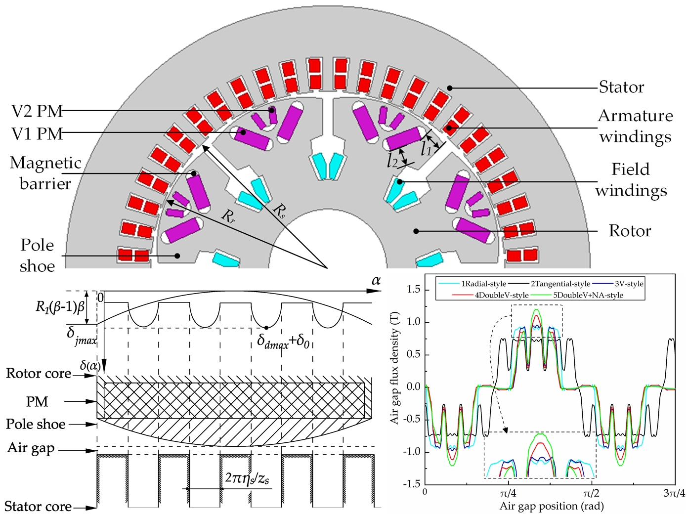
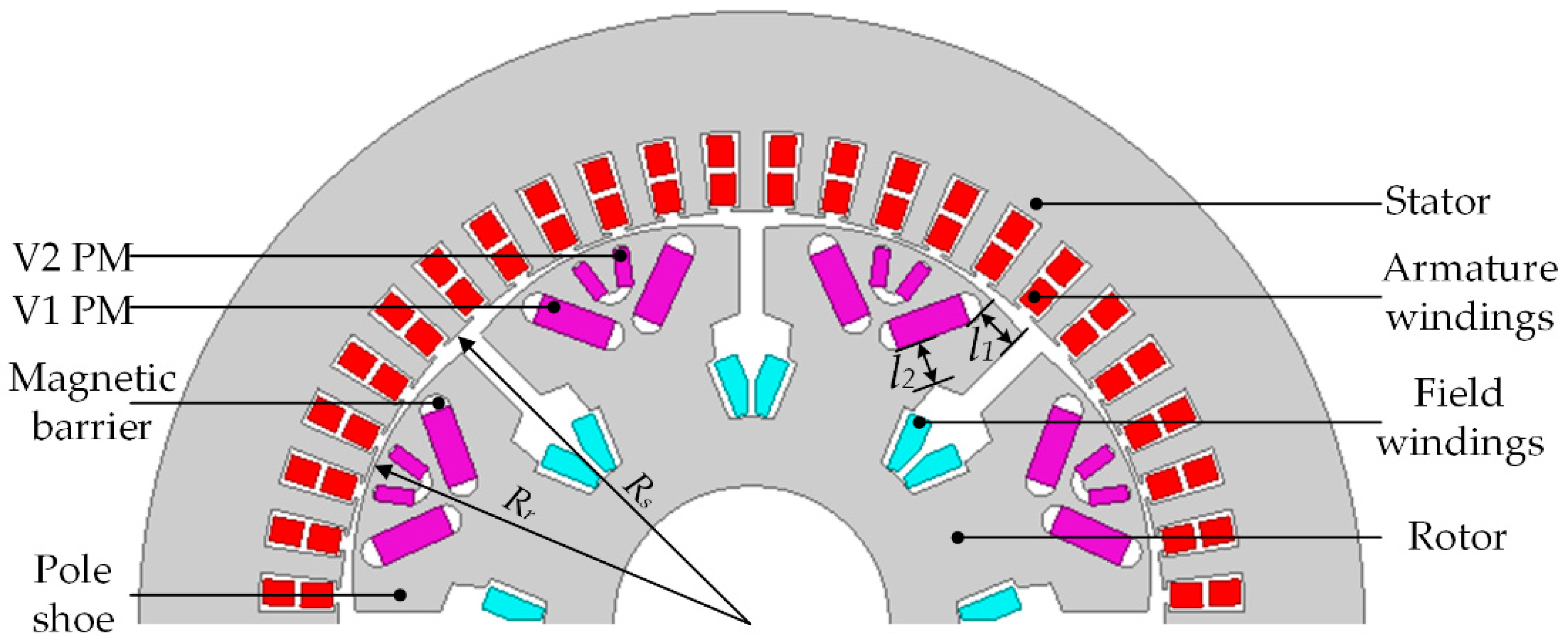
2.1. Topology Structure

Figure 1 shows the two-dimensional structure of the motor. V1 PMs are embedded in the middle of the outer side of the salient pole core in such a way that the N poles and S poles are alternately arranged on each salient pole. V2 PMs are sequentially embedded in the outer side of V1 PMs. The outside polarities of V1 PMs and V2 PMs in a single salient pole are the same. The rotor core consists of an even number of non-arc pole shoes. The excitation winding is wound on the salient poles in series. The stator is similar to that of a traditional PMSM and is built in a three-phase distributed armature winding. The permanent magnetic pole on the rotor is regarded as the structure of the embedded double radial magnetic pole. Two V1 PMs together provide air-gap magnetic flux for each pole, which brings about a clear magnetism effect. The V2 PM is designed in the outer middle of the V1 PMs, which can increase the main air-gap magnetic flux and avoid the problem of sinking at the output voltage peaks. Rs and Rr are the radius of the stator core and rotor core, and l1 and l2 are the lengths of the magnetic bridges at the corresponding positions.

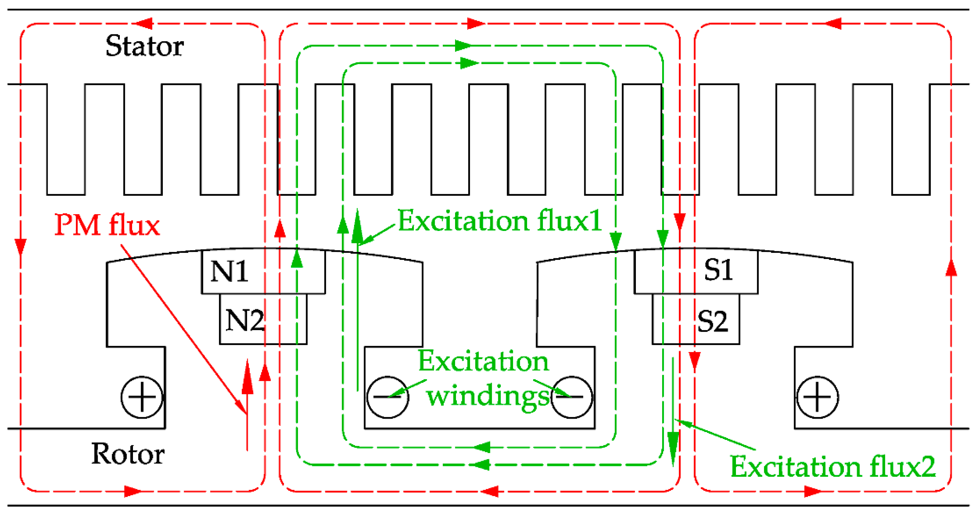
2.2. Characteristics of Magnetic Circuit and Operating Principle

There are two MMF sources in the HSEM: PM and electric excitation MMF. The MMF of PMs is used as the main excitation source of the HSEM. For the V-type combined magnetic pole, only its radial flux is considered. Therefore, it is approximately regarded as two “flat-type” combined magnetic poles, which forms the dual radial flux. When the winding is energized, the polarity of the salient poles can be changed. According to the operating conditions of the HESM, there are two magnetic paths, in which a situation is formed that is mainly in parallel and auxiliary in series.
Figure 2 describes the operating principle of the HESM. When starting and driving at low speed, the flux is provided only by the PMs for the output torque; that is, only PM flux exists in the magnetic path. It can be seen that the PM flux combined with non-arc pole shoes is beneficial to adjusting the distribution of the air-gap flux density flexibly, so that the sine degree of the air-gap flux density waveform can be improved greatly. When operating under high torque conditions, the electrical flux created by excitation winding passes through the magnetic bridges on the left and right sides of the PMs and enters the air-gap; that is, electrical and PM flux are in parallel. With the increasing of the excitation current, when the magnetic bridges are saturated, part of the electrical flux can pass through the PMs directly into the air-gap; that is, electrical and PM flux are in series. It can be seen that the flux of the air-gap can be adjusted by changing the excitation current to achieve the adjustment of the speed and output torque.
In addition, since the PMs are embedded in the middle of the outside of the salient pole, the MMF generated by the shock current of the armature winding can form a loop through the magnetic bridges. The shock current does not pass through the PMs, which avoids the danger of the irreversible demagnetization of the PMs.

3. Analytical Calculation of Magnetic Field

3.1. Descriptions of Model and Assumptions

Since the relative permeability of the pole shoes and the iron core are large, the magnetic potential drop of the stator and rotor core are much smaller than that of the air.
The following assumptions are made for the analytical calculation of air-gap flux density:
  • The effects of the end of windings and magnetic saturation are ignored [26,27,28];
  • The permeability of the core is infinite;
  • PMs are magnetized in parallel, the demagnetization curve of PMs is linear, and the conductivity of the PMs is zero.

3.2. The Formula of Air-Gap Flux Density

In the polar coordinate, the magnetic vector potential φ is governed by Laplace’s equation as follows:
2 φ r 2 + 1 r φ r + 1 r 2 2 φ α 2 = 0
where α is the angular position in the air-gap, and r is the radius of the calculated air-gap.
The general solution for the above equation can be obtained as
φ ( r , α ) = ν = 1 [ A ν ( r R s ) ν + B ν ( r R r ) ν ] cos ( ν α ) + ν = 1 [ C ν ( r R s ) ν + D ν ( r R r ) ν ] sin ( ν α )
where ν = 1, 2, 3,…, are the harmonic orders of field distribution in the air-gap.
The magnetic flux density satisfies
B r = 1 r φ α a n d B α = φ r
Based on Kirchhoff’s law, the magnetic flux density at any point in the air-gap is derived as follows:
B r ( r , α ) = Λ r ( r , α ) ψ P M ( α , t ) / A a i r
As shown in Equation (4), the key to calculating the magnetic flux density is to get the MMF ψPM(α, t) created by dual-V PMs embedded in the rotor and the non-uniform air-gap permeance function Λr(r, α) caused by non-arc pole shoes and stator slots, where Aair is the magnetic flux size at the radius of the calculated air-gap.

3.3. MMF Model of Rotor with Dual-Layer Combined PMs

The rotor MMF created by PMs in the stator coordinate system is generally expressed as
ψ P M ( α , t ) = ν ψ ν P M cos [ ν ( α α t ) ] = ν ψ ν P M cos ( ν α t ) cos ( ν α ) + ν ψ ν P M sin ( ν α t ) sin ( ν α )
where ψνPM is the amplitude of the rotor MMF, and αt is the rotor position at time t.
Due to the different distribution of the rotor MMF, the MMF created by PMs can be expressed in the following three expressions as follows:
When the distribution of the rotor MMF is sinusoidal-shaped:
ψ ν P M = { θ P ψ P M π ( sin ( ( ν + 1 ) θ P 2 ) ( ν + 1 ) θ P 2 + 1 ) f o r ν = 1 θ P ψ P M π ( sin ( ( ν + 1 ) θ P 2 ) ( ν + 1 ) θ P 2 + sin ( ( ν 1 ) θ P 2 ) ( ν 1 ) θ P 2 ) f o r v 1
When the distribution of the rotor MMF is trapezoid-shaped:
ψ ν P M = 8 p ψ P M ν 2 π β θ i sin ( ν ( θ P + β θ i ) 2 ) sin ( ν β θ i 2 )
When the distribution waveform of the rotor MMF is rectangular-shaped:
ψ ν P M = 4 ψ P M ν π sin ( ν θ p 2 )
where θP is the pole arc of the calculation rotor, and βθi is the pole arc of the calculation magnetic bridges.
In the proposed HESM, there are two pairs of built-in V-shaped PMs with the same polarity and different volumes in each pole, and the number of pole pairs of is four; the MMF created by PMs in the HESM is shown in Figure 3.
Since the corresponding mechanical angle of each magnetic pole is π/4, the period of the MMF is π/2. According to the principle of the minimum reluctance, the two peaks of the MMF are separately provided by V1 and V2 PMs, respectively. Thus, for the the proposed new topology, when the number of pole pairs is p and ν/p = 1, 3, 5,…, the amplitude of the rotor MMF is
ψ ν P M = ψ ν 1 Θ ν ( p , θ p 1 , θ k 1 ) + ( ψ ν 2 ψ ν 1 ) Θ ν ( p , θ p 2 , θ k 2 )
and when ν/p = 2, 4, 6,…, the amplitude of the rotor MMF is
ψ ν P M = 0
where
Θ ν ( p , θ p i , θ k i ) = 8 p ν 2 π θ k i sin ( ν θ p i + θ k i 2 ) sin ( ν θ k i 2 )
where ψνi is the MMF created by the ith layer PMs, θPi is the pole arc of the ith layer PMs, and θki is the pole arc of the magnetic bridges of the ith layer PMs.
When HC is the remanent magnetic field strength, combining Equations (9)–(11), the expression of the MMF of the new topology can be obtained as
ψ ν P M = 16 k m a g p 2 H C ν 2 π 2 R s [ b m 1 2 ( θ P 1 θ P 2 ) θ k 1 sin ( ν θ p 1 + θ k 1 2 ) sin ( ν θ k 1 2 ) + 1 θ k 2 ( b m 2 2 θ P 2 b m 1 2 ( θ P 1 θ P 2 ) ) sin ( ν θ p 2 + θ k 2 2 ) sin ( ν θ k 2 2 ) ]
where bmi is the equivalent radial thickness of ith layer PMs, kmag = 2ΣhmiPi, hmi is the width of ith layer PMs.

3.4. Relative Permeance Function Using MEC Method

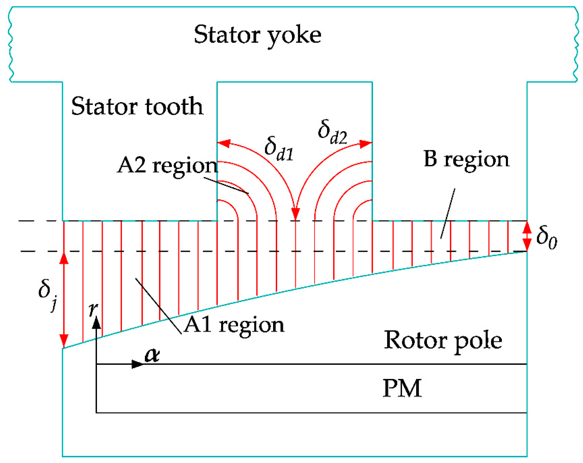
3.4.1. Equivalent Air Length Model in Magnetic Path

Figure 4 shows typical magnetic field lines at different locations in the HESM. It can be seen that the air lengths of different regions in the magnetic circuit are different. In the A1 and A2 regions, the air lengths can change with the position angle α. In the B region, the air length does not change with the position angle α. δj and δ0 are the air lengths of the pole shoe and air-gap, respectively, and δd1 and δd2 are the air lengths of the stator slot.
1. Air length in the A1 region
To calculate the air length in the A1 region, the shape and main geometric parameters of the outer edge of the pole are shown Figure 5. R1 is the radius of the rotor’s outside edge, R2 is the radius of the rotor’s inside edge, and θpe is the pole arc of the proposed rotor. The radius of the outside edge of the pole shoe is equal to the radius of the rotor core.
If the outside edge of the pole shoe is regarded as a parabola opening downward, the horizontal line passing through the middle point of the outside edge is regarded as the X axis, and the vertical line passing through the left endpoint of the pole shoe is regarded as Y axis. Applying the three-point analytical method, the air length in the A1 region can be derived and simplified as
δ j ( α ) = ( β 1 ) β [ 16 ( 4 α 2 + ( 8 ( θ P e θ P 1 ) + 1 ) R s α + ( θ P e θ P 1 ) 2 ) π 2 R s θ P e 2 + ( 16 ( θ P e θ P 1 ) + π θ P e ) R s π θ P e ] = 16 ( β 1 ) β π θ P e [ ( α + 1 2 ( θ P e θ P 1 ) ) + 4 ( α + ( θ P e θ P 1 ) 2 ) 2 π R s θ P e ] + R s ( β 1 ) β
where β is the salient pole ratio, β = R1/R2.
2. Air length in the A2 region
The air lengths in A2 region are regarded as two quarter circles in parallel: the radius of quarter circle δd1(α) is equal to the length between the calculated point and the endpoint of the adjacent stator tooth, and the radius of quarter circle δd2(α) is equal to the length between the calculated point and the endpoint of the adjacent stator tooth on the other side. If the pole-arc coefficient of the stator is ηs, the number of stator slots is Zs, and the lengths of two quarter circles can be calculated:
{ δ d 1 ( α ) = π R s 2 sin ( α ( 1 η s ) 2 π Z s + θ P e θ P 1 2 ) δ d 2 ( α ) = π R s 2 sin ( π ( 2 η s ) Z s θ P e θ P 1 2 α )
Thus, the equivalent air length in the A2 region can be arranged:
δ d ( α ) = { 0 , α [ 0 , π Z s θ P e θ P 1 2 ] π R s sin ( α ( 1 η s ) 2 π Z s + θ P e θ P 1 2 ) sin ( ( 2 η s ) π Z s θ P e θ P 1 2 α ) 2 sin ( π η s 2 Z s ) cos ( α + θ P e θ P 1 2 + ( 3 η s 4 ) π 2 Z s ) , α [ π Z s θ P e θ P 1 2 , 2 π Z s ]
3. Air length for the 48-slot/eight-pole motor
According to the calculation results in Equations (13) and (15), the air length under a single magnetic pole is calculated as shown in Figure 6, in which the reluctance is constantly changing. Moreover, the variance of air length near the ends of the magnetic pole is greater than that of the air length in the middle of the magnetic pole, which indicates the air-gap flux density can be adjusted rapidly by changing the salient pole ratio of the pole shoe in theory.

3.4.2. Fourier Series Expansions of Magnetic Path Permeance Function

According to [29], the Fourier series expansions of the magnetic path permeance function are as follows:
Λ δ _ u n s o ( α ) = Λ 0 + k = 1 Λ k cos ( k α )
where
Λ 0 = θ λ Λ max + ( π θ λ ) Λ min π
Λ k = 2 ( Λ max Λ min ) sin ( k θ λ ) k π
where θλ is the pole arc between two adjacent magnetic poles, and Λmax and Λmin are the maximum and minimum values of permeance, respectively.
Based on the principle of reluctance minimization, the magnetic flux path generally goes directly through the permanent magnets. Without considering the stator open-slotting, and considering the effect of the non-arc pole shoes, the permeance function of the HESM is calculated:
Λ δ _ u n s o ( α ) = μ 0 μ r A i δ i ( α )
where μ0 is the permeability of the vacuum, μr is the relative permeability, and Ai and δi are the size and air lengths of different parts in the magnetic path, respectively.
The Fourier series expansions of permeance function in stator slots are as follows:
Λ δ _ s o ( α ) = Λ δ _ s o , 0 + k = 1 Λ δ _ s o , m cos ( k Z s α )
where
Λ δ _ s o , 0 = μ 0 A s o π 2 η s 2 R s 6 Z s
Λ δ _ s o , m = μ 0 A s o R s 2 Z s k 2 { ( cos ( 2 π k η s ) ) 2 π k sin ( 2 π k η s ) + 1 }
The total relative permeance function considering the effects of the non-arc pole shoes and the stator open-slotting can be obtained as
Λ δ ( α ) = Λ min + Λ δ _ s o , 0 + k = 1 Λ δ _ s o , m cos ( k Z s α )
Combining Equations (4), (5), (19) and (23), the air-gap flux density of the proposed HESM as a result of the non-arc pole shoes and stator open-slotting is derived as
B s ( α ) = Λ ( r , α ) ψ P M ( α , t ) / A a i r = ( μ 0 A a i r ( A 0 δ 0 ( α ) + A j δ j ( α ) + μ r A P M δ P M ( α ) ) + π R s η s 6 A a i r Z s ) ν ψ ν P M cos ( ν α ) + 1 2 A a i r ν k = 1 ψ ν P M Λ s o , m cos [ ( ν ± k Z s ) α + ( ν k Z s ) α ]
where A0, Aj, and APM are the corresponding flux size of the air-gap, the pole shoe and PMs, respectively, and δPM is the equivalent air length of PM in the magnetic path.

4. Finite Element Analysis

According to the proposed motor parameters listed in Table 1, an electromagnetic performance simulation is performed to verify the rationality of the motor design and the correctness of the theoretical model. Firstly, the finite element models of five motors with different rotor structures are established and solved. Secondly, for the air-gap flux density, the simulation results are compared with the analytical calculation results. Finally, the magnetic linkage curve is obtained by changing the excitation current.

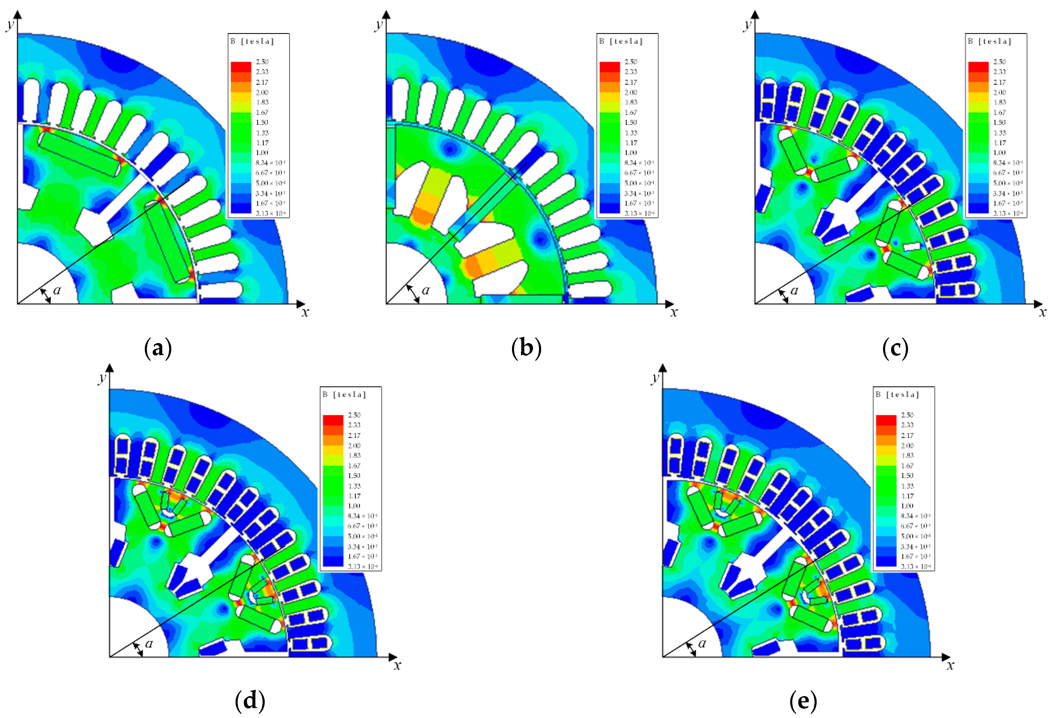
4.1. FEM Model of Five Motors with Different Rotor Structures

The eight-pole, 48-slot salient HESMs with flat-type PMs, spoke-type PMs, V-type PMs, dual-V-type PMs and dual-V-type PMs with non-arc pole shoes, respectively, are chosen as the simulation objects. The FEM models of the simulation objects are simulated by the commercial software Ansoft Maxwell 16. The material of PMs is set to NdFeB magnets. To eliminate the effect of iron core saturation on the field distribution, the material of the stator and rotor iron core in the FEM model is laminated linear steel. The analysis radius of the air-gap flux density is close to the rotor surface to decrease the effect of the non-smooth stator surface. The stator structure and PM properties of the five models are the same. Considering that the number of PMs in the V-type motor is twice that of the PMs in flat-type and spoke-type motors, the width of the PMs in the V-type motor is half that of PMs in flat-type and spoke-type motor. The magnetic flux strength distributions are shown in Figure 7.

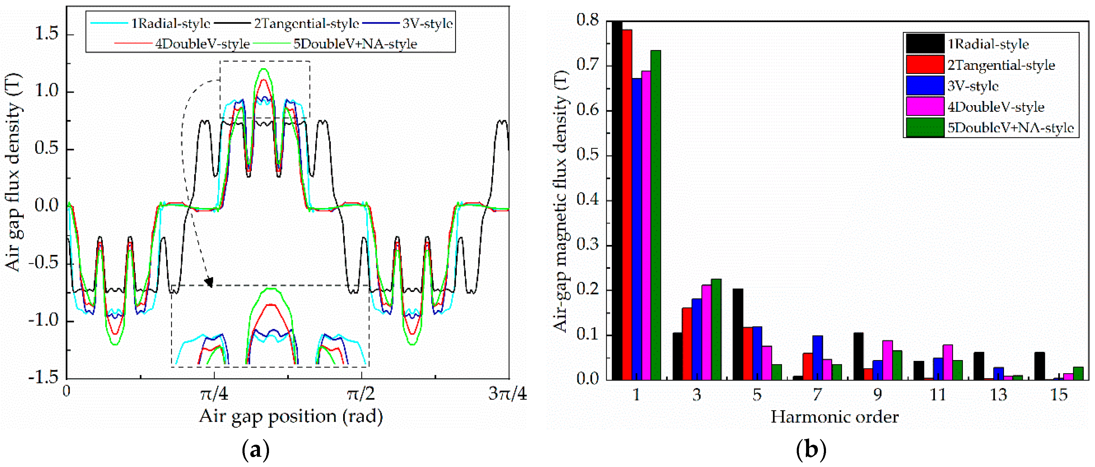
4.2. Comparisons of Air-Gap Flux Density

The waveforms and harmonic orders of the air-gap flux density are shown in Figure 8, which is obtained by FEM. Since the PMs in the motors studied in this paper are magnetized in parallel, the result of the air-gap flux density obtained by the FEM is the radial magnetic density. Considering the cogging effect, the magnetic flux amplitude at the corresponding stator slot is decreased to a certain extent.
Figure 8a shows that the air-gap flux density amplitude of the spoke-type motor is the lowest. The reason for this is that part of the magnetic flux directly passes through the rotor core to form a closed magnetic leakage circuit. The air-gap flux density waveforms of the flat-type motor and the spoke-type motor are wider at the top, presenting rectangular or square waves, and those of the V-type motor and the flat-type motor are almost the same; however, the amplitude in the V-type motor is slightly increased. In the dual-V-type motor and dual-V-type motor with non-arc pole shoes, the width of the waveform at the top is reduced significantly, and the sinusoidal degree is obviously better than that of the first three motors. As shown in Figure 8b, in the dual-V-type motor with non-arc pole shoes, except for the third harmonic, the remaining harmonics decrease obviously. These results are consistent with the theoretical analysis in Section 3. Since the dual-V-type motor with non-arc pole shoes combines the dual effects of magnetization and drag reduction, the effective value of the air-gap flux density reaches 0.7 T.

4.3. Verification of Analytical Method

Establishing a coordinate system as shown in Figure 7, the flux density of typical points in the air-gap that have obvious periodic characteristics can be calculated by combing Equations (5) and (23). By the method of curve fitting, the flux density curve of the dual-V-type motor can be obtained as shown in Figure 9a; that is, the curve is shown in the analytical method in Figure 9a. In a similar way, the flux density curve of the dual-V-type with non-arc pole shoes can also be obtained as shown in Figure 9b.
As shown in Figure 9, whether dual-V-type or dual-V-type with non-arc pole shoes, there is a small error between the results of the analytical method and FEM, but the trend is almost the same. A small error is caused by ignoring the magnetic potential drop of the core, which indicates that the analytical model can be used to calculate and analyze the static characteristics of dual-V-type and dual-V-type with non-arc pole shoe HESMs proposed in this paper.

4.4. Capacity of Magnetic Field Regulation

When the HESM is working in the magnetized or weakened state, the magnetic field in the air-gap can be expressed as
Φ δ = Φ δ P M + Φ δ E = B s A a i r ± ψ i ( Λ 0 + Λ δ _ s o + Λ j + Λ d + Λ σ ) = ψ P M ( Λ 0 + Λ δ _ s o + Λ j + Λ d + Λ P M ) ± N I f ( Λ 0 + Λ δ _ s o + Λ j + Λ d + Λ σ )
where
{ Λ σ = μ 0 μ r A σ δ σ = μ 0 μ r L e f l 1 δ σ f o r l 1 < l 2 Λ σ = μ 0 μ r A σ δ σ = μ 0 μ r L e f l 2 δ σ f o r l 1 > l 2
In Equation (25), ψi is the MMF created by excitation windings, which reveals that, when excitation current is applied, there is one more item Λσ in the permeance function than that of the conventional salient machine, where N is the number of field winding turns and If is the field current. According to Equation (26), Λσ can be changed with the length l1, l2. Further, by designing the length l1, l2 in Figure 1 reasonably, the expected electric excitation flux can be obtained, meeting the requirement of magnetic flux regulation and obtaining a good magnetization capacity. It is proved that the flux can be adjusted efficiently.
Figure 10 shows the magnetic flux linkage of the HESM under different excitation currents. It can be seen that, when the excitation current is changed, the flux linkage changes significantly, which indicates that the effect of flux regulation is good. With the increase of the excitation current, the saturation of the magnetic circuit increases and the change rate of the magnetic flux becomes small, and the effect of the magnetizing is weakened.

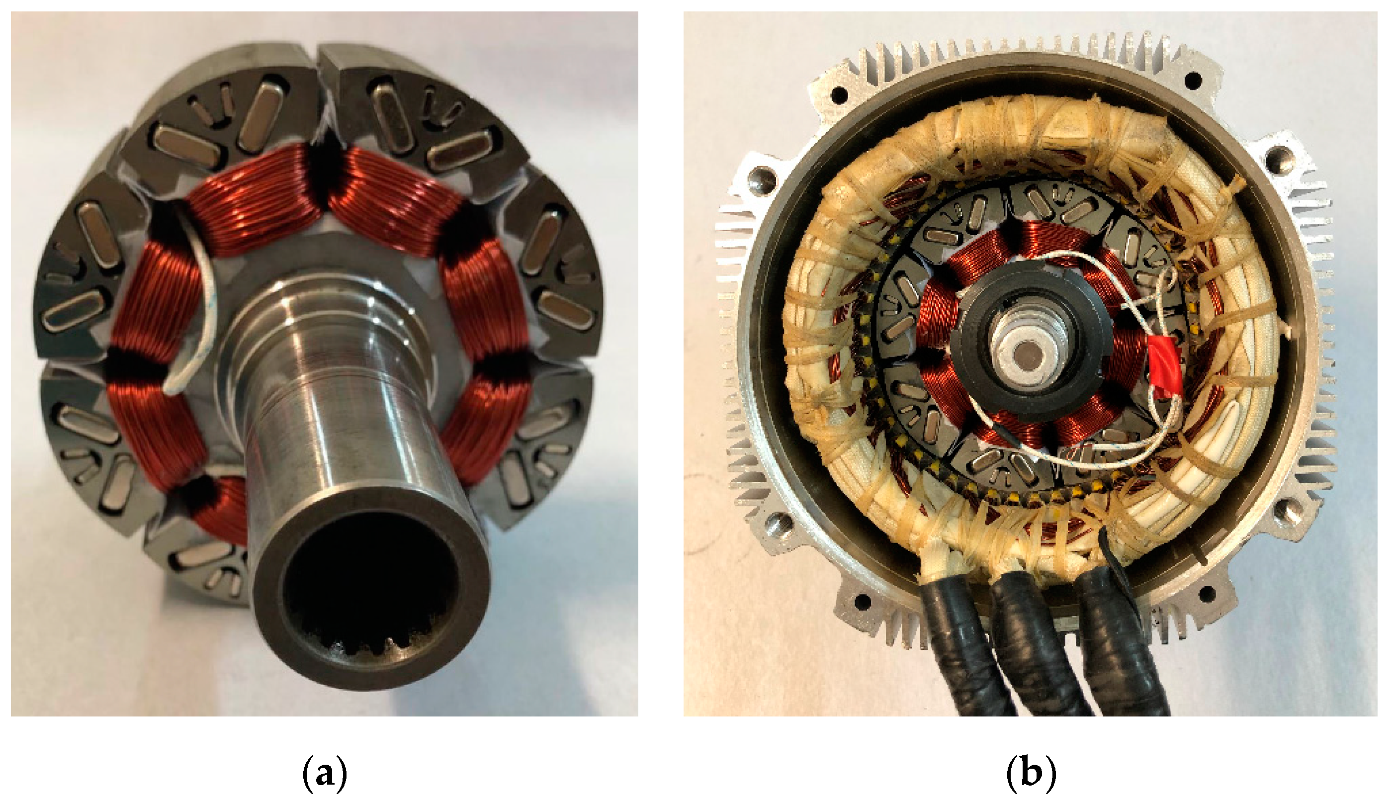
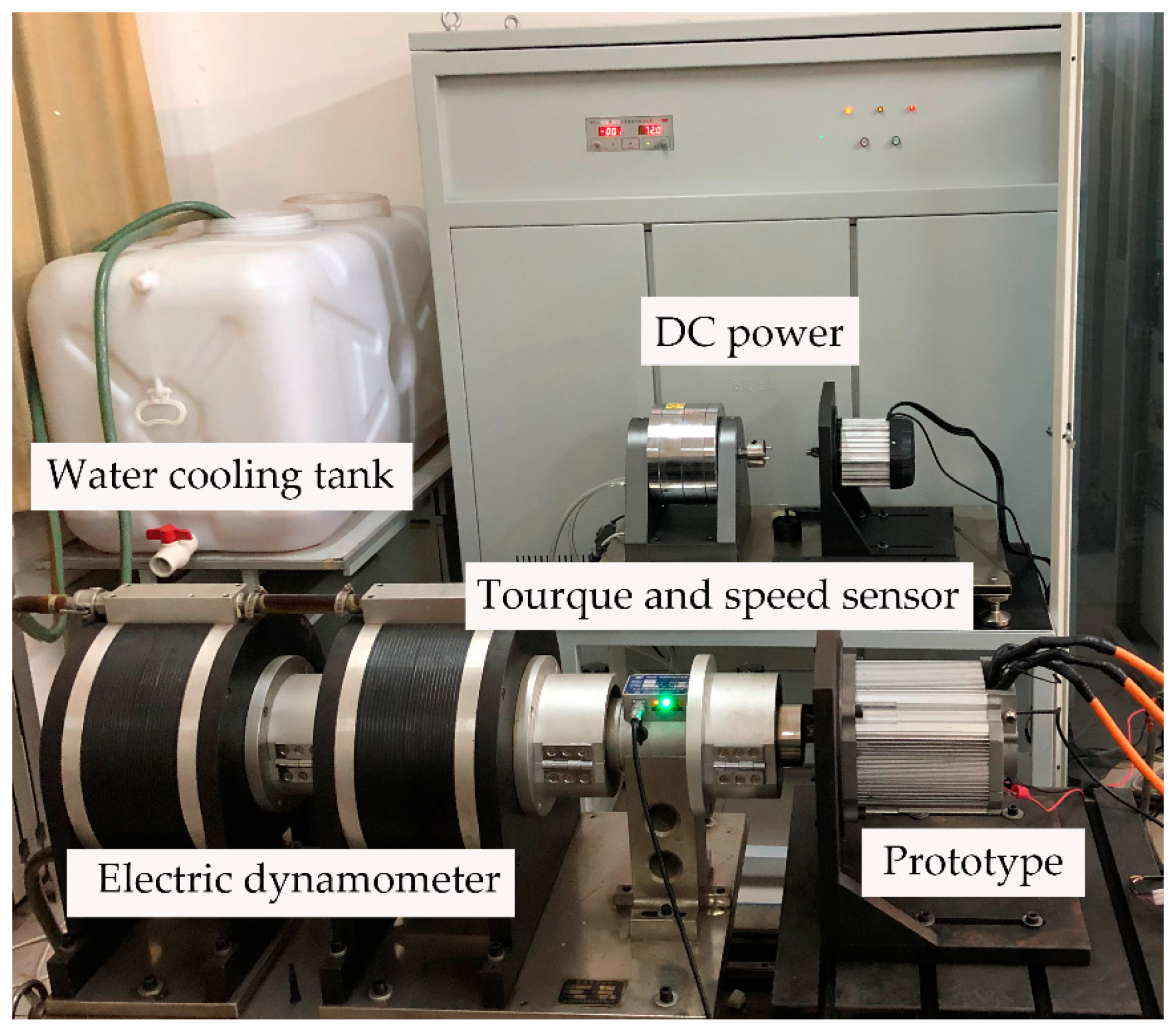
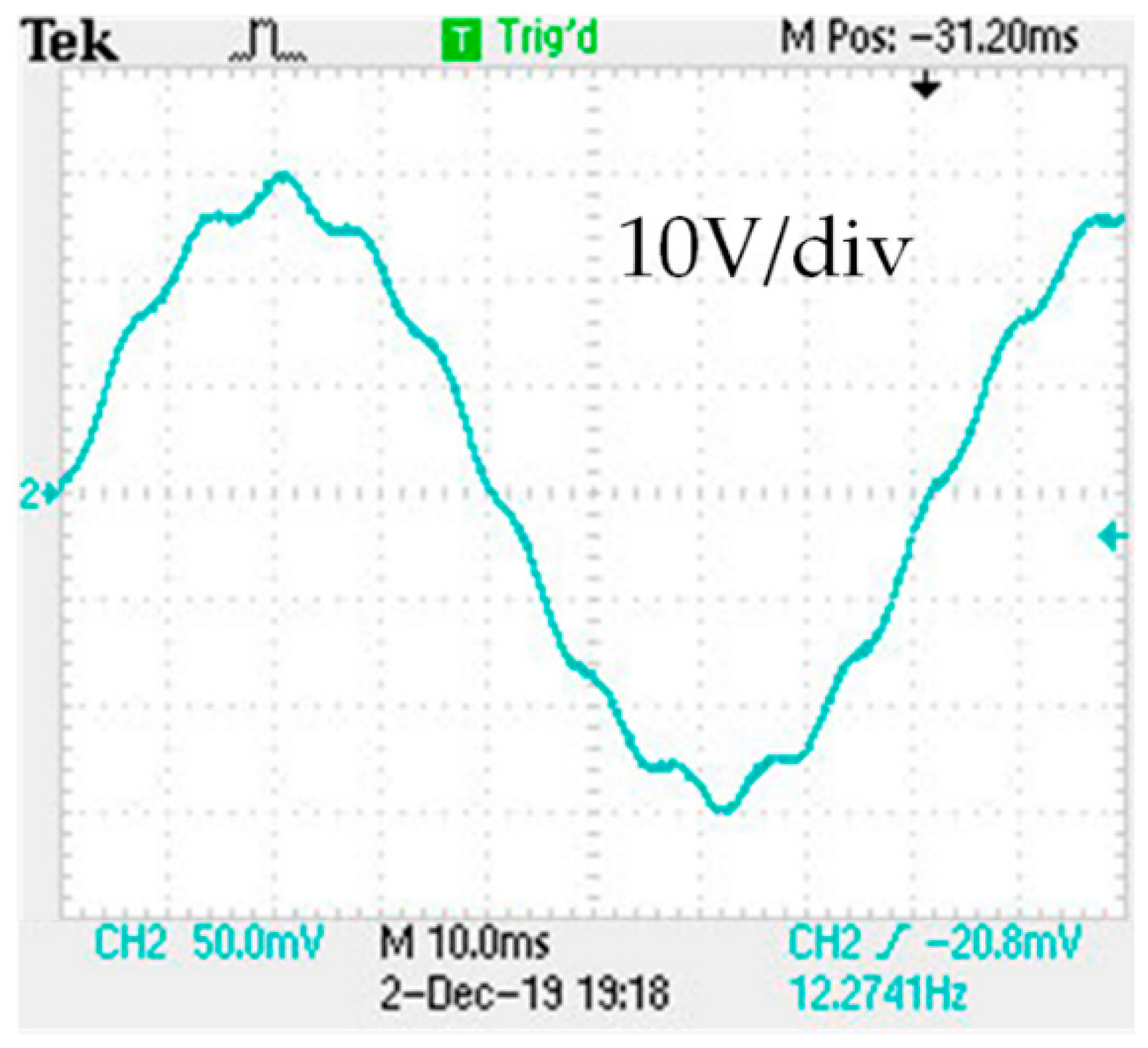
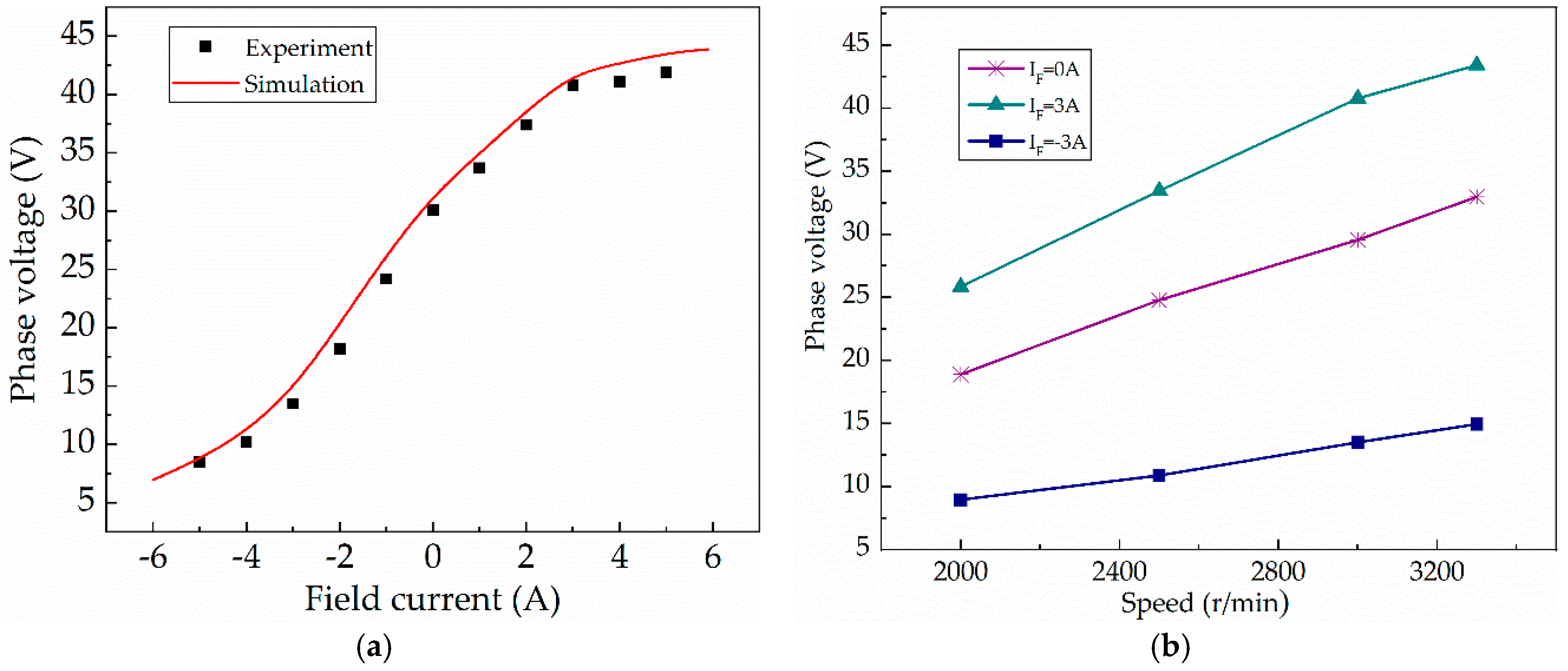
5. Experiments and Verification

We design a 48-slot, eight-pole prototype as the target machine to verify the correctness of the analytical model and the electromagnetic performance of the studied HESM in this paper. The rotor core and the assembly of the prototype HESM are shown in Figure 11. The parameters of the prototype used in the experiment are introduced in Section 4. The set-up of the experimental platform is shown in Figure 12.
Figure 13 shows the experimental result of the no-load back-EMF at 3000 r/min. The measured amplitude of the back-EMF is 30.1 V, in contrast to the 31.4 V obtained by FEM. The difference is small, which is mainly caused by manufacturing tolerances and various losses, especially core loss. The measured voltage does not present the rectangular waveform presented by the traditional flat-type or spoke-type motor. It shows a quasi-sinusoidal waveform and solves the problem of high flux distortion, which means that the new topology proposed in this paper feasibly improves the sine of the air-gap flux density waveform.
The comparisons of back-EMF obtained by the test and FEM are shown in Table 2. The relative error εr is calculated by
ε r = | V t e s t V F E M V F E M | × 100 %
where VFEM represents the back-EMF results calculated by the FEM method, and Vtest represents the back-EMF results measured by prototype dragged by prime mover.
In Figure 14a and Table 2, the simulation and experimental results of the no-load flux regulation capacity are compared, showing that the experimental results are consistent with simulation results. Along with the increasing of the excitation current in the enhanced magnetic field mode, the back-EMF is increased from 30.1 V to 41.1 V, which means that the magnetic flux regulation rate is 36.54%. In addition, without excitation current, the entire magnetic field is provided by PMs. In order to increase the power density, PM components need to be increased to increase the initial magnetic flux. However, the width of the magnetic bridge can be reduced correspondingly, which will weaken the magnetic flux regulation rate and the efficiency of field excitation. Meanwhile, since the pole body space is limited, the increase of the PMs will cause the pole body to saturate prematurely, and the efficiency of field excitation will still be weakened. Therefore, when designing the HESM, we should comprehensively consider the power density and magnetic regulation capacity.
Figure 14b shows the amplitudes of back-EMF at different speeds. We keep the excitation current at 3 A and adjust the speed to 2000, 2500, 3000 and 3200 r/min to obtain the back-EMF. Similarly, when the excitation current is 0 A and −3 A, the back-EMF at different speeds can also be obtained. When the exciting current is ±3 A, the average field weakening and magnetizing amplitudes are 56.1% and 33.2%, respectively. The magnetic regulation effect is obvious. Only a relatively small excitation current can be used to obtain a good air-gap flux regulation capacity to meet the needs of wide speed motors.
Table 3 and Figure 15 show the experimental external characteristics of the prototype with excitation currents of 0A, 1A, 2A and −2A, respectively. It can be seen that, for a given excitation current, the output torque increases linearly with the increasing of armature current. For a given armature current, the output torque increases obviously with the increasing of excitation current. With a rated armature current of 87 A (rated value), the excitation current is 2 A and −2 A, and the output torque is increased by 42.3% and decreased by 59.8%, respectively, compared to the torque tested without the excitation current. It can be found that the prototype has good load capacity.

6. Conclusions

In this paper, the topology, operation principle, analytical model of magnetic field distribution and the flux regulation capacity of a new HESM with non-arc pole shoes and built-in dual-V PMs are studied. The simulation results of the magnetic field are consistent with the analytical results. The tested back-EMF waveform reveals that the proposed topology is a feasible design method to improve the sine of the air-gap flux density. The experiment and simulation results of motor performance further validate that the air-gap flux can be adjusted effectively by changing the excitation current.
(1) The HESM adopts a salient pole rotor with built-in dual-V PMs and non-arc pole shoes, and the topology can improve the sine of the air-gap flux density waveform, which solves the problem of the high waveform distortion rate of the traditional salient pole HESM.
(2) In the proposed analytical model, the MMF with dual-V combined PMs is derived on the principle of minimum magnetic resistance; the permeance at any point can be equivalent to the superposition of the corresponding permeance in the air-gap, stator slot and pole shoe. The analytical method can be used to calculate the static characteristics of the new type of HESM, whether or not there are non-arc pole shoes.
(3) When the excitation current is ±3 A, the amplitudes of the magnetization and weakening field are greater than 30% under no-load and load conditions, which reveals that the HESM has good flux regulation and carrying load capacities.
In summary, this paper provides a good theoretical reference for an HESM with interior PMs, including the work of structure design and analytical models for the magnetic field of this type of HESM. However, in order to further explore the performance and control of the novel motor, in future research, the control strategy, noise, etc. will be studied in depth to provide theoretical support for the design and optimization of higher-performance motors.

Author Contributions

Conceptualization, W.H.; funding acquisition, X.Z. and L.S.; investigation, W.H.; methodology, W.H. and L.S.; project administration, X.Z.; resources, H.Y.; software, W.H.; supervision, X.Z.; validation, H.Y. and H.G.; visualization, Y.Z.; writing—original draft, W.H.; writing—review & editing, W.H. and H.Y. All authors have read and agreed to the published version of the manuscript.

Funding

This research was funded by the National Natural Science Foundation of China, grant number (51875327 and 51975340).

Conflicts of Interest

The authors declare no conflict of interest.

Nomenclature

NEVNew energy vehicles
HESMHybrid excitation synchronous motor
PMPermanent magnet
MMFMagnetomotive force
MECMagnetic equivalent circuit
RsRadius of the stator core
RrRadius of the rotor core
αAngular position
rRadius of the calculated air-gap
ψPMRotor MMF
AairMagnetic flux size at the radius of the calculated air-gap
θPPole arc of the calculation rotor
βθiPole arc of the calculation magnetic bridges
pNumber of pole pairs
θPiPole arc of the ith layer PMs
θkiPole arc of magnetic bridges of the ith layer PMs
bmiEquivalent radial thickness of ith layer PMs
hmiWidth of ith layer PMs
δdiAir length of stator slot
δjAir length of pole shoe
δ0Air length of air-gap
R1Radius of the rotor outside edge
R2Radius of the rotor inside edge
θpePole arc of the proposed rotor
βSalient pole ratio
μ0Permeability of the vacuum
μrRelative permeability
ηsPole-arc coefficient of the stator
ZsNumber of stator slots
A0Flux size of air-gap
AjFlux size of the pole shoe
APMFlux size of the PM
δPMEquivalent air length of PM in the magnetic path

References

  1. Lee, C.; Angle, M.; Bhalla, K.; Qasim, M.; Mei, J.; Mohammadi, S.; Iyer, K.; Sinkular, J.; Kirtley, J. Quantitative Comparison of Vernier Permanent-Magnet Motors with Interior Permanent-Magnet Motor for Hybrid Electric Vehicles. Energies 2018, 11, 2546. [Google Scholar] [CrossRef] [Green Version]
  2. Ma, F.; Yin, H.; Wei, L.; Wu, L.; Gu, C. Analytical calculation of armature reaction field of the interior permanent magnet motor. Energies 2018, 11, 2375. [Google Scholar] [CrossRef] [Green Version]
  3. Zhang, X.; Du, Q.; Ma, S.; Geng, H.; Hu, W.; Li, Z.; Liu, G. Permeance analysis and calculation of the double-radial rare-earth permanent magnet voltage-stabilizing generation device. IEEE Access 2018, 6, 23939–23947. [Google Scholar] [CrossRef]
  4. Kim, J.M.; Jang, J.Y.; Chung, J.; Hwang, Y.J. A New Outer-Rotor Hybrid-Excited Flux-Switching Machine Employing the HTS Homopolar Topology. Energies 2019, 12, 2654. [Google Scholar] [CrossRef] [Green Version]
  5. Zhang, X.; Du, Q.; Ma, S.; Hu, W.; Geng, H. Magnetic flux analysis and performance test of permanent magnet and claw-pole electromagnetic hybrid excitation generator for electric vehicle range extender. Intl. J. Elec. Hybri. Veh. 2017, 9, 187–205. [Google Scholar] [CrossRef]
  6. Zhang, X.; Zhao, X.; Niu, S. A Novel Dual-Structure Parallel Hybrid Excitation Machine for Electric Vehicle Propulsion. Energies 2019, 12, 338. [Google Scholar] [CrossRef] [Green Version]
  7. Du, Y.; Lu, W.; Wang, Q.; Zhu, X.; Quan, L. Comparative investigation of hybrid excitation flux switching machines. Energies 2018, 11, 1428. [Google Scholar] [CrossRef] [Green Version]
  8. Devornique, G.; Fontchastagner, J.; Netter, D.; Takorabet, N. Hybrid model: Permeance network and 3-D finite element for modeling claw-pole synchronous machines. IEEE Trans. Magn. 2017, 53, 1–4. [Google Scholar] [CrossRef] [Green Version]
  9. Zhao, X.; Niu, S.; Ching, T. Design and analysis of a new brushless electrically excited claw-pole generator for hybrid electric vehicle. IEEE Trans. Magn. 2018, 54, 1–5. [Google Scholar] [CrossRef]
  10. Rebhi, R.; Ibala, A.; Masmoudi, A. MEC-based sizing of a hybrid-excited claw pole alternator. IEEE Trans. Ind. Appl. 2014, 51, 211–223. [Google Scholar] [CrossRef]
  11. Wu, Y.; Sun, L.; Zhang, Z.; Miao, Z.; Liu, C. Analysis of Torque Characteristics of Parallel Hybrid Excitation Machine Drives with Sinusoidal and Rectangular Current Excitations. IEEE Trans. Magn. 2018, 54, 1–5. [Google Scholar] [CrossRef]
  12. Geng, W.; Zhang, Z.; Jiang, K.; Yan, Y. A new parallel hybrid excitation machine: Permanent-magnet/variable-reluctance machine with bidirectional field-regulating capability. IEEE Trans. Ind. Electron. 2014, 62, 1372–1381. [Google Scholar] [CrossRef]
  13. Wang, Y.; Deng, Z.; Wang, X. A parallel hybrid excitation flux-switching generator DC power system based on direct torque linear control. IEEE Trans. Energy Convers. 2012, 27, 308–317. [Google Scholar] [CrossRef]
  14. Zhang, Z.; Dai, J.; Dai, C.; Yan, Y. Design considerations of a hybrid excitation synchronous machine with magnetic shunt rotor. IEEE Trans. Magn. 2013, 49, 5566–5573. [Google Scholar] [CrossRef]
  15. Liu, Y.; Zhang, Z.; Zhang, X. Design and optimization of hybrid excitation synchronous machines with magnetic shunting rotor for electric vehicle traction applications. IEEE Trans. Ind. Appl. 2017, 53, 5252–5261. [Google Scholar] [CrossRef]
  16. Kamiev, K.; Nerg, J.; Pyrhönen, J.; Zaboin, V.; Hrabovcová, V.; Rafajdus, P. Hybrid excitation synchronous generators for island operation. IET Electr. Power Appl. 2012, 6, 1–11. [Google Scholar] [CrossRef]
  17. Afinowi, I.; Zhu, Z.; Guan, Y.; Mipo, J.; Farah, P. Hybrid-excited doubly salient synchronous machine with permanent magnets between adjacent salient stator poles. IEEE Trans. Magn. 2015, 51, 1–9. [Google Scholar] [CrossRef]
  18. Gaussens, B.; Hoang, E.; Lécrivain, M.; Manfe, P.; Gabsi, M. A hybrid-excited flux-switching machine for high-speed DC-alternator applications. IEEE Trans. Ind. Electron. 2013, 61, 2976–2989. [Google Scholar] [CrossRef] [Green Version]
  19. Zhao, J.; Lin, M.; Fu, X.; Huang, Y.; Xu, D. An Overview and New Progress of Hybrid Excited Synchronous Machines and Control Technologies. Chin. Soc. Elec. Eng. 2014, 34, 5876–5887. [Google Scholar]
  20. Capponi, F.G.; Borocci, G.; De Donato, G.; Caricchi, F. Flux regulation strategies for hybrid excitation synchronous machines. IEEE Trans. Ind. Appl. 2015, 51, 3838–3847. [Google Scholar] [CrossRef]
  21. Liu, Y.; Zhang, Z.; Wang, C.; Gao, H. Optimization and Performance Improvement of a Hybrid Excitation Synchronous Machine with Modular Magnetic-Shunting Rotor. IEEE Trans. Ind. Electron. 2019, 67, 4381–4390. [Google Scholar] [CrossRef]
  22. Ayub, M.; Jawad, G.; Kwon, B.-I. Consequent-Pole Hybrid Excitation Brushless Wound Field Synchronous Machine with Fractional Slot Concentrated Winding. IEEE Trans. Magn. 2019, 55, 8203805. [Google Scholar] [CrossRef]
  23. Hussain, A.; Atiq, S.; Kwon, B.-I. Consequent-pole hybrid brushless wound-rotor synchronous machine. IEEE Trans. Magn. 2018, 54, 1–5. [Google Scholar]
  24. Ning, Y.; Liu, C. Analysis and calculation of electromagnetic and temperature field in a hybrid excitation synchronous generator. Int. J. Appl. Electromagn. Mech. 2016, 50, 435–448. [Google Scholar] [CrossRef]
  25. Ning, Y.; Liu, C.; Zhu, S.; Tang, J. Design and finite element analysis of a hybrid excitation synchronous machine. Int. J. Appl. Electromagn. Mech. 2015, 48, 11–19. [Google Scholar] [CrossRef]
  26. Zhou, Y.; Li, H.; Meng, G.; Zhou, S.; Cao, Q. Analytical Calculation of Magnetic Field and Cogging Torque in Surface-Mounted Permanent-Magnet Machines Accounting for Any Eccentric Rotor Shape. IEEE Trans. Ind. Electron. 2015, 62, 3438–3447. [Google Scholar] [CrossRef]
  27. Wu, L.J.; Zhu, Z.Q. Simplified Analytical Model and Investigation of Open-Circuit AC Winding Loss of Permanent-Magnet Machines. IEEE Trans. Ind. Electron. 2014, 61, 4990–4999. [Google Scholar] [CrossRef]
  28. Liu, Y.-X.; Li, L.-Y.; Gao, Q.-H.; Cao, J.-W.; Wang, R.-H.; Sun, Z.-Y. Analytical Model of Torque-Prediction for a Novel Hybrid Rotor Permanent Magnet Machines. IEEE Access 2019, 7, 109528–109538. [Google Scholar] [CrossRef]
  29. Dajaku, G.; Gerling, D. Stator slotting effect on the magnetic field distribution of salient pole synchronous permanent-magnet machines. IEEE Trans. Magn. 2010, 46, 3676–3683. [Google Scholar] [CrossRef]
Figure 1. Topology structure of hybrid excitation synchronous motor (HESM). PM: permanent magnet.
Energies 13 01501 g001
Figure 2. The magnetic flux path of HESM under different conditions.
Energies 13 01501 g002
Figure 3. Magnetomotive force (MMF) created by PMs.
Energies 13 01501 g003
Figure 4. Air length in different positions of the magnetic path.
Energies 13 01501 g004
Figure 5. The shape and main geometric parameters of the pole shoe.
Energies 13 01501 g005
Figure 6. Air length of the magnetic path under one magnetic pole.
Energies 13 01501 g006
Figure 7. Magnetic flux strength distributions of the five motors: (a) Flat-type PMs; (b) spoke-type PMs; (c) V-type PMs; (d) dual-V-type PMs; (e) dual-V-type PMs with non-arc pole shoes.
Energies 13 01501 g007
Figure 8. Comparison of the simulation results for air-gap flux density: (a) waveform of the air-gap flux density; (b) harmonic content of the air-gap flux density.
Energies 13 01501 g008
Figure 9. The analysis and simulation results for the air-gap flux density: (a) dual-V-type motor; (b) dual-V-type motor with non-arc pole shoes.
Energies 13 01501 g009
Figure 10. Magnetic flux linkage under different excitation currents.
Energies 13 01501 g010
Figure 11. The proposed HESM: (a) the rotor; (b) the prototype.
Energies 13 01501 g011
Figure 12. The test platform.
Energies 13 01501 g012
Figure 13. No-load back-EMF waveform without excitation current.
Energies 13 01501 g013
Figure 14. No-load characteristics: (a) flux regulation capacity; (b) back-EMF at different speeds.
Energies 13 01501 g014
Figure 15. Output torque with different armature currents and field currents.
Energies 13 01501 g015
Table 1. Parameters of the proposed motor.
ItemsUnitValue
Stator outer diametermm160
Stator outer diametermm107
Number of rotor pole/8
Number of stator slot/48
Air gap lengthmm0.5
Phase number/3
Rotor outer diametermm106
Rate speedr/min3000
Rate torqueNm16
Rate powerKw5
Table 2. Comparison of back-EMF by the finite element method (FEM) and test results.
If (A)−4−3−2−101234
VFEM (V)11.1314.7220.0326.2531.3534.9638.6041.7943.14
Vtest (V)10.213.518.424.230.133.737.440.841.1
εr (%)8.368.298.147.813.993.63.112.374.7
Table 3. The output torque with different excitation currents.
Ia (A)1020304050607080
If (A)
01.122.183.374.355.346.537.788.69
11.422.934.355.667.168.259.8711.01
21.583.274.776.547.929.4811.2512.51
−20.370.831.091.551.822.292.572.95

