Article

Comparative Study of the Effective Release Energy, Residual Gas Fraction, and Emission Characteristics with Various Valve Port Diameter-Bore Ratios (VPD/B) of a Four-Stroke Spark Ignition Engine

1
Graduate School of Mechanical Engineering, University of Ulsan, Ulsan 44610, Korea
2
Faculty of Automobile Technology, HaNoi University of Industry, Ha Noi 100000, Viet Nam
3
School of Mechanical Engineering, University of Ulsan, Ulsan 44610, Korea
*
Author to whom correspondence should be addressed.
Energies 2020, 13(6), 1330; https://doi.org/10.3390/en13061330
Submission received: 4 February 2020 / Revised: 2 March 2020 / Accepted: 11 March 2020 / Published: 12 March 2020

Abstract

:
In this research, the residual gas, peak firing pressure increase, and effective release energy were completely investigated. To obtain this target, the experimental system is installed with a dynamo system and a simulation model was setup. Through combined experimental and simulation methods, the drawbacks of the hardware optimization method were eliminated. The results of the research show that the valve port diameter-bore ratio (VPD/B) has a significant effect on the residual gas, peak firing pressure increase, and effective release energy of a four-stroke spark ignition engine. In this research, the engine was performed at 3000 rpm and full load condition. Following increased IPD/B ratio of 0.3–0.5. The intake port and exhaust port diameter has a contrary effect on engine volumetric efficiency, the residual gas ratio increase 27.3% with larger intake port and decrease 18.6% with larger exhaust port. The engine will perform optimal thermal efficiency when the trapped residual gas fraction ratio is from 13% to 14%. The maximum effective release energy was 0.45 kJ at 0.4 intake port-bore ratio, and 0.451 kJ at 0.35 exhaust port-bore ratio. The NOx emission increases until achieved a maximum value after that decrease even VPD/B was still increasing. With a VPD/B ratio of 0.35 to 0.4, the engine works without the misfiring.

1. Introduction

There are a large number of motorcycles in operation today, with that number constantly increasing, the goal of improving motorcycle engine power, while satisfying Euro-5 emission standards, is worth investigating. Two essential factors in the study of engines are engine efficiency and the reduction of pollutant emissions. The residual gas fraction is known as effective factors, which influence energy efficiency and pollution engine exhaust gas. The trapped residual gases in the combustion chamber will premix with the fresh air-fuel and take part in the next combustion stroke. This trapped exhaust residual gases also effect on the NOx emission of the engine. The peak pressure increase shows the increasing pressure value per crankshaft angle, this peak pressure increase is expected higher value to reduce heat loss and improve engine efficiency. An effective method for determining the residual gases, effective energy, and peak pressure is necessary.
As stated earlier, the estimation of the effect of hardware factors and software factors on engine power and reduce pollution emission were presented such as: changing cam profiles [1], re-designing the intake pipe [2], recovering heat lost from the cooling system [3], using optimal ignition timing at each engine speed [4], and effect of intake port diameter [5,6].
Can et al. [1] have studied the effects of valve lift on the engine performance and emissions of a homogeneous charge compression ignition (HCCI) engine. The conditions of the experiment were 800 rpm to 1900 rpm engine speed, 0.5 to 2 air-fuel ratio, and 20 °C to 120 °C air temperature. In this research, the intake valve lift and exhaust valve lift were reduced from 9.5 mm to 2 mm. The results of the experiments show that the intake and exhaust valve lifts have a substantial effect on the performance and emission of an HCCI gasoline engine. The mixture of air and fuel into the cylinder increases when the intake valve lift increases. The maximum indicated mean effective pressure (IMEP) of the engine was 11.007 bars, the intake valve lift was 5.5 mm, and the exhaust valve lift was 3.5 mm. When using low cam lifts, the engine operation ranges are extended to include misfiring and knocking conditions. Zhang et al. [7] presented a study on the effects of changing valve timing and cam lift in controlled auto-ignition combustion. In their study, a single cylinder engine was used. The valve lift was changed from 0.3 mm to 9.5 mm. The results showed that: the low cam lifts effected the heat release rate and pressure in the cylinder. Ghazal et al. [8] presented the effect of various inlet valve diameters at different inlet valve opening, inlet valve closing and valve overlap on a spark-ignition engine performance. In their research, a spark-ignition engine was conducted with engine speed band from 500 to 3500 rpm. The original inlet port diameter is 31 mm and exhaust port diameter is 26 mm. The inlet diameters were 29, 30, 31, 32, and 33 mm was presented. The results showed that the decrease of the inlet valve close angle of all inlet port diameters is due to decrease engine power and increase NO and CO emissions. A reduction of valve overlap till 50 deg crank angle could improve engine power. Raghu et al. [9] presented the effect of intake port parameters on the air motion characteristics of a diesel engine. The intake port parameters were analyzed such as: intake valve diameter, valve seat angle and width, intake port eccentricity, and orientation angle. In their research, the results showed that the geometries of the combustion chamber and intake port had a significant effect on the flow into the cylinder. They also found that, when the intake valve diameter increased from 43 to 55 mm, the swirl ratio decreased 27.61% with directed port and decreased 17.65% with helical port. Yasar et al. [10] also experimented with an internal combustion engine to study the effect of various intake port shapes on the intake air flow motion in the cylinder. In order to analyze the air flow behavior and to measure air flow velocity distribution, a particle image velocimetry technique (PIV) was employed in their research. Their results showed that the intake port geometry had a sensitive effect on the air flow structure into the cylinder. The valve lift was 7 mm and intake valve seat angle was 30 degrees, the inlet flow into the cylinder was a jet flow. Most of the air flow direction followed the axial direction; a reversed flow appeared due to the presence of the side wall of the cylinder. Qi et al. [11] used CFD simulation model to study the effects of intake port geometry on the intake air flow characteristics in the cylinder of an SI-engine. They found that a small change of intake port has a significant effect on in-cylinder flow. A suitable inlet port design helps to increase tumble and reduce recirculation of the intake air flow. A strong tumble leads to increase the homogeneity of air-fuel and improve the stability of combustion. Their final design improved by 20% of the fuel vaporization. Latheesh et al. [12] also studied with a compression ignition engine to analyze the designed intake port and exhaust port by using the CFD simulation model. In that research, the exhaust port was increased form two valves to four valves. They found that by using the simulation software helps to save the number of times in experiments and the swirl motion generated inside the cylinder was sensibly affected by the position of tangential and helical intake port.
All previous studies lacked detail on the investigation the effect of exhaust port diameter-bore ratio on effective release energy, residual gas fraction and engine emission characteristics. These studies focus to present the inlet port configuration effect on intake air flow characteristics such as: swirl ratio, air flow motion, flow velocity distribution, or air flow tumble. There are no articles present in detail the residual gas, effective release energy with various intake and exhaust port. A comparison between the two cases is necessary. This is an existing gap in the open literature will be filled up through the work presented in this paper.
Residual gas fraction and combustion duration has a large effect on NOx, HC, and CO emissions; on the other hand, the peak firing pressure increase and effective release energy are the roots of engine efficiency. Therefore, this paper also presents an accurate method to investigate the residual gas, peak firing pressure increase, combustion duration, and effective release energy of a spark-ignition engine at various VPD/B.

2. Experimental Setup, Material, and Methods

2.1. Experiment Setup

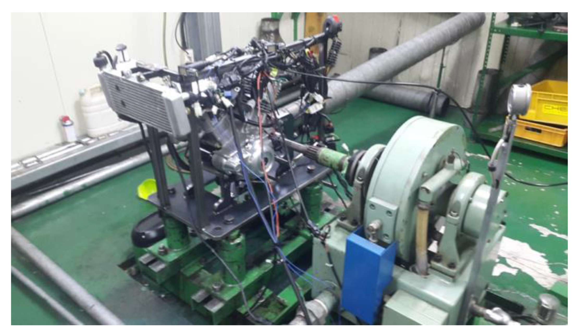
A four-stroke, spark-ignition engine with 137 cm3 in displacement volume of each cylinder was used. There are two intake valves and exhaust valves in each cylinder. The exhaust valves and intake valve were controlled by two different camshafts. Figure 1 and Figure 2 show the experimental setup schematics [13] and experimental engine setup system [14]. The experiment was conducted with engine speed band of 2000–8000 rpm, 11.8:1 is the compression ratio of the engine, and the air/fuel ratio was kept at 13.6 and 29.5–30 °C of the temperature of intake air during experiments. Before doing the experiments, all the tested devices were calibrated. The system resistant moment was controlled by a dynamometer controller. During the engine performance the oil temperature was maintained at 80 °C and the engine was cooled by using air, and the oil temperature was determined and controlled by thermal couple and temperature sensors. The injector controller was used to maintain the air-fuel ratio at 13.6. The steady state of engine performed was present in the experiments. At each engine speed the throttle angle was kept at 100% of opening. The pressure and temperature in the combustion chamber are determined by using pressure sensor is located on the engine head. In this experimental system, the VPD/B ratio (both intake and exhaust valve) of the original engine is 0.4.
The devices were used in the experiment system: a dynamo testing system controller (1), AVL’s hydraulic/water brake dynamometer with a serial number ZAG56907 (Horiba Korea Ltd, Ulsan, Korea) (2), the connecting shaft (3) to connect the engine to the dynamometer. The experimental engine (4), the encoder Autonics E40S8-1800-3-T-24(Horiba Korea Ltd, Ulsan, Korea) (6) is located on the flywheel (5). To prevent engine working in knocking condition a knocking sensor 30530-P2M-A01(Horiba Korea Ltd, Ulsan, Korea) (7) was employed. The fuel tank (8), fuel pump (9), fuel filter (10) and injector denso (16450-C12-235) (Horiba Korea Ltd, Ulsan, Korea) (11) were the fuel system’s parts. The sensors (12) and (13) were used to determine the exhaust gas temperature and oxygen in the exhaust gas. The cylinder pressure sensor Kistler 6056A (14) was located on the engine’s head. The air cleaner box (15) and throttle (16), an air-heater (17) was used to remain temperature of air flow from 29.5–30 °C. The air flowing meter (18) and ECU (20) are used to determine air flow and control injection timing and ignition timing. The monitor (19), encoder’s signal convertor (21), and a computer (22) were used to observe and analyze input data. The exhaust emissions (NOx, HC, and CO), were measured using an emission analyzer (HoribaMEXA-7100DEGR) (Horiba Korea Ltd, Ulsan, Korea).

2.2. Applied Engine

The experiments are carried out on a spark-ignition engine. Table 1 shows the specifications of experimental engine.

2.3. Simulation Model Setup

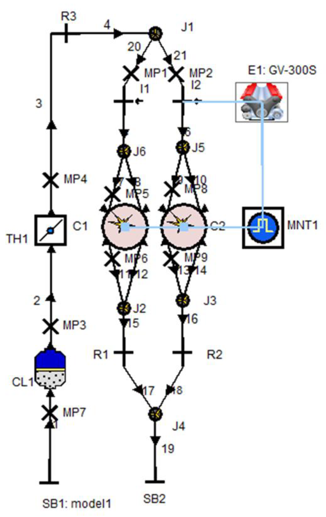
It was complicated to determine the effective energy, trapped residual gases, and pressure increase in the combustion chamber through experiments with the various testing conditions. Simulation method is powerful and effective tools to eliminate this problem, and AVL-Boost software was employed to estimate the influence of the intake and exhaust port diameter to bore ratio of residual gases, peak pressure increase, and effective energy. This AVL-Boost software is well-known in the field of internal combustion engines. It helps researchers simulate various combustion engine types, such as SI engines [13,14], compression ignition (CI) engines [15,16], diesel engines with turbocharger [17,18], and engines using alternative fuel [19]. Figure 3 shows our simulated model of the spark-ignition engine [14].
Figure 3 presents the simulation model. The simulation model’s elements represent the experimental engine parts. The engine parts’ characteristics were defined in simulation elements. The steady state or transient state of the testing engine condition is selected in the element E1. The monitor, MNT1, helps research observer interesting output data such as engine brake torque, residual gas, and effective energy. The system boundary conditions of the exhaust and intake tube were defined in elements SB1 and SB2. The air cleaner CL1 helps to filter air into the combustion chamber. The TH1 element helps to control the throttle angle. In the experiments, the throttle angle was kept at 100%, and the restriction in the exhaust and intake tubes was defined by R1, R2, and R3. The junction (J1, J2, J3, J5, and J6) collects or distributes the air flow in the pipe. Measurements MP1 and MP2 on the exhaust and intake pipes defines the airflow characteristics. I1 and I2 is injector provides fuel to cylinders C1 and C2.
Combustion model:
The vibe function was used to determine heat release characteristics
d x d α = α α ( m + 1 ) y m . e α . y ( m + 1 )
d x = d Q h Q h ; y = α α 0 α c
The faction burned in mass ε can be calculated
ε = d x d α d α = 1 e α . y ( m + 1 )
The combustion chamber’s heat transfer
Q T = A . q c o e f f . ( T c T w )
The air mass flow rates were calculated
d m d t = A e f f . P 1 . 2 R 0 T 1 . C
C = K K 1 [ ( P 2 P 1 ) 2 K ( P 2 P 1 ) K + 1 K ]
The residual gas fraction was calculated from the Equation (5)
x S O C c p = V c V ρ . x c p . d V V c V ρ . d V
where ρ is local cylinder density (kg/m3); V is local cylinder volume (m3); xcp is local cylinder combustion product mass fraction at SOC.
The concentration of N2O and the production rate of NO were determined by Equations (6) and (7)
C N 2 O = 1.1802.10 6 . T 0.6125 . e 9471.6 T . C N 2 . P O 2
r NO = 2 . C p . C K . [ 1 λ 2 ] . r 1 1 + λ . R 1 . r 4 1 + R 2
The production rate of CO emission was calculated by Equation (8)
r CO = C C o n s t . ( r 1 + r 2 ) . ( 1 φ ) φ = C NO , a c t C NO , e q u
The unburned HC mass was calculated by Equation (9)
m HC = P C . V c r e v i c e . M R . T p i s t o n
Air mass flow has a large impact on the performance of internal combustion engines. If the air mass flow into the cylinder in the limited band is increased while keeping the air-fuel ratio constant, the injected fuel into the cylinder increases. As a result, the maximum pressure in the cylinder would increase and the engine would perform at a higher torque. To improve the power of small SI-engines, several methods have been presented, such as reducing the restriction of the intake tube and reducing the bending tube in the intake tube system.
The air mass flow into the cylinder was calculated by Equation (10)
d m d t = A e f f . p 01 . 2 R g . T 01 .   ψ
where d m d t is mass flow rate; A e f f is effective flow area; p 01 is upstream stagnation pressure; T 01 is upstram stagnation temperature; R g is gas constant.
For subsonic flow
ψ = K k 1 [ ( p 02 p 01 ) 2 K ( p 02 p 01 ) K + 1 K ]
For sonic flow
ψ = ( 2 K + 1 ) 1 K 1 . K k + 1
where K is ratio of specific heats;     p 02 is downstream static pressure.

3. Results and Discussion

3.1. Model Validation

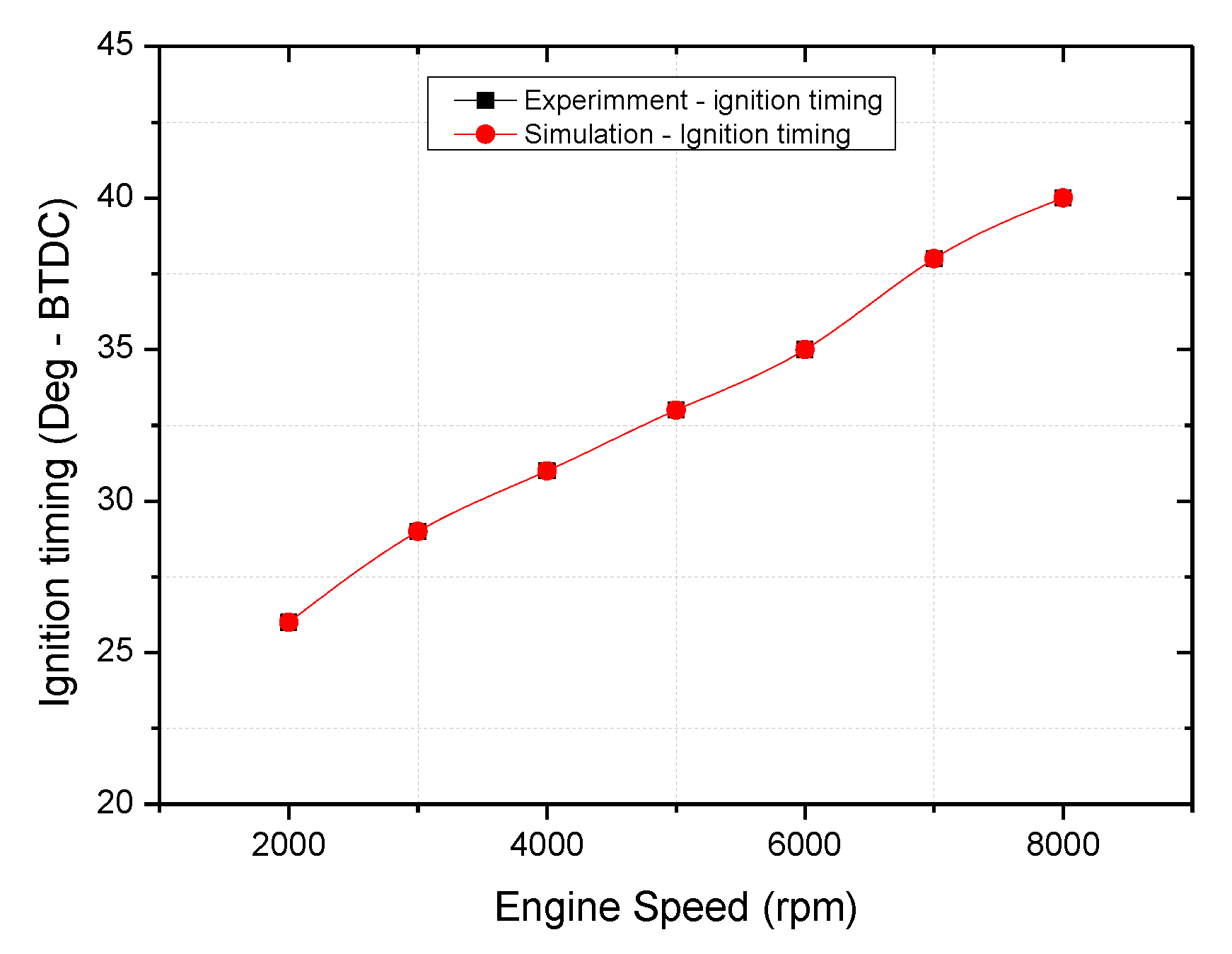
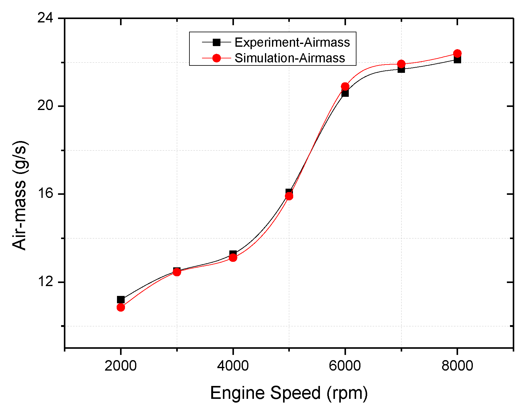
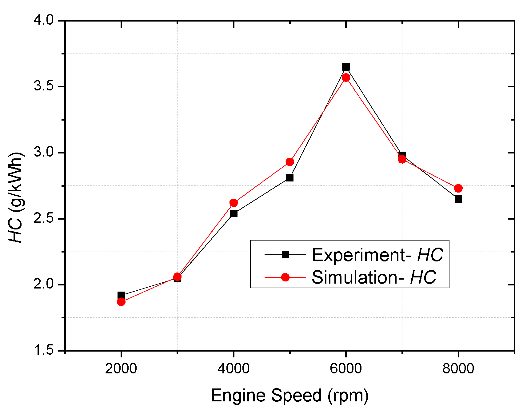
For validation of the model, experimental data were used. Comparisons between experimental results and simulated results are shown in Figure 4, Figure 5, Figure 6, Figure 7, Figure 8, Figure 9 and Figure 10. The black curves describe experimental results; the red curves describe simulated results.
The ignition timing for each engine speed in both cases is shown in Figure 4. Because the ignition timing is an input data for the simulation model, it can be seen that the experimental values for ignition timing were very close to the simulated values.
In the internal combustion engine with air-fuel ratio is constant, the air mass flow is a most sensitive factor which affects the fuel mass. Figure 5 shows a comparison between experimental and simulated results in an air mass flow. The air-mass flow is changed while the air-fuel ratio is constant. The maximum difference between simulation and experimental result was 1.42% at 6000 rpm. It is acceptable because the experimental value of air mass flow is the average value.
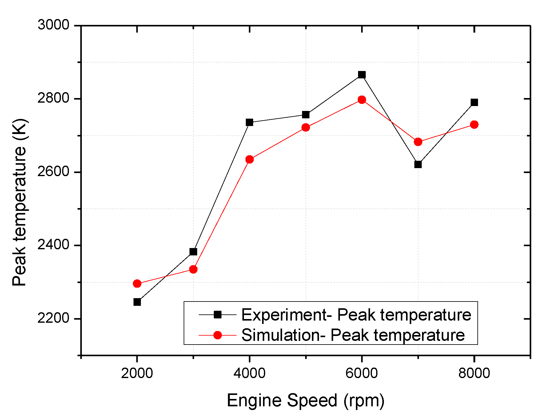
The peak firing temperature is known as an important factor which has a strong effect on NOx emission. Figure 6 shows a comparison between experimental and simulated results for peak firing temperature. The values for the two cases are not much different at each engine speed. The maximum differential was 5.34% at 4000 rpm.
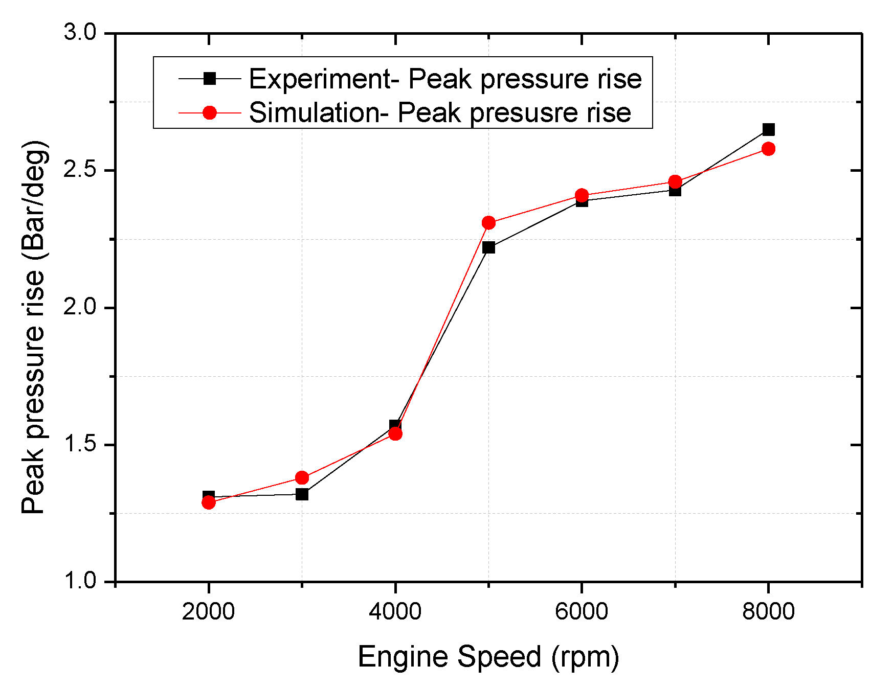
Figure 7 shows the validation peak firing pressure increase. It can be seen that the values of peak firing pressure increase in the two cases are almost same at each engine speed. The maximum difference was 4.5% at 5000 rpm. During the combustion stroke, a better homogeneous air-fuel mixture leads to a full transient from chemical energy to the thermal energy and increase peak pressure in a shorter time to reduce heat loss and improve energy efficiency.
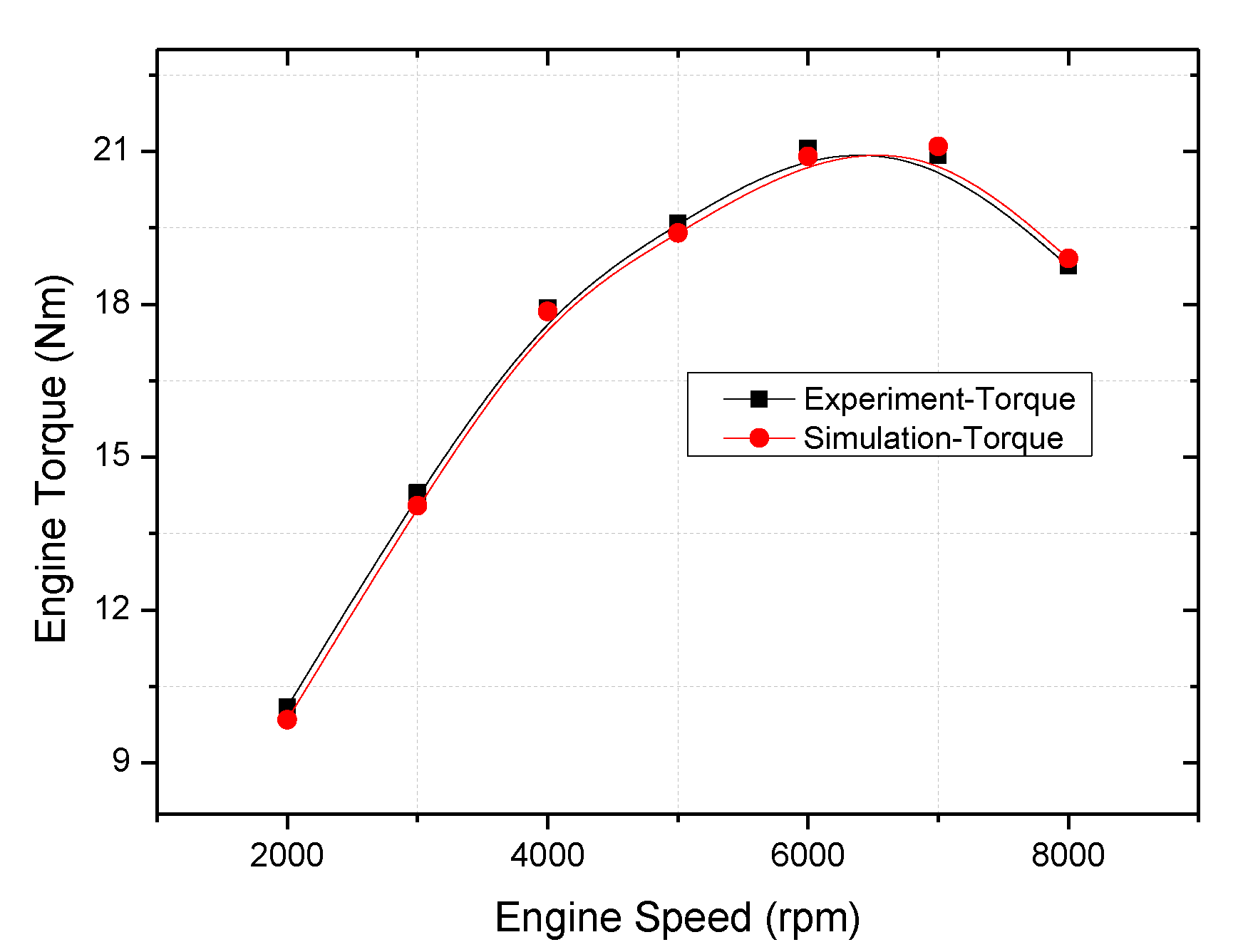
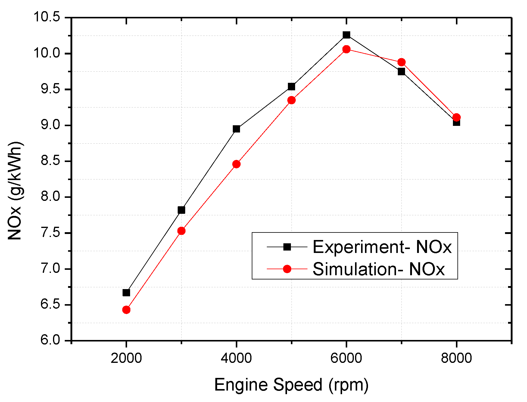
Figure 8 shows a comparison between experimental and simulated results for engine torque. The maximum difference is 0.9% at 8000 rpm. The engine toxic exhaust gases not only pollute environment, it is also harmful to human health. In this research, the emission characteristics will be estimated and discussed in detail. The validation of NOx and HC emission are presented through Figure 9 and Figure 10.
When comparing the experiment and simulation results, the similar values of two cases are determined. The maximum difference in NOx emission is 6.5% at 4000 rpm and the maximum difference in HC is 4.3% at 5000 rpm.
From the comparison between experimental results and simulation results of the applied engine, all of the results in two cases are same, so the simulation model made by AVL-Boot software has good accuracy in prediction of engine performance.

3.2. Comparative Studies the Effect of Various Valve Port Diameter-Bore Ratios on Effective Release Energy and Emission Characteristics

The results were studied of two VPD/B ratio cases.
Case 1: intake port diameter changes while the exhaust port diameter is 22 mm.
Case 2: exhaust port diameter changes while the intake port diameter is 22 mm.
The various of intake and exhaust port diameters were presented in Table 2:
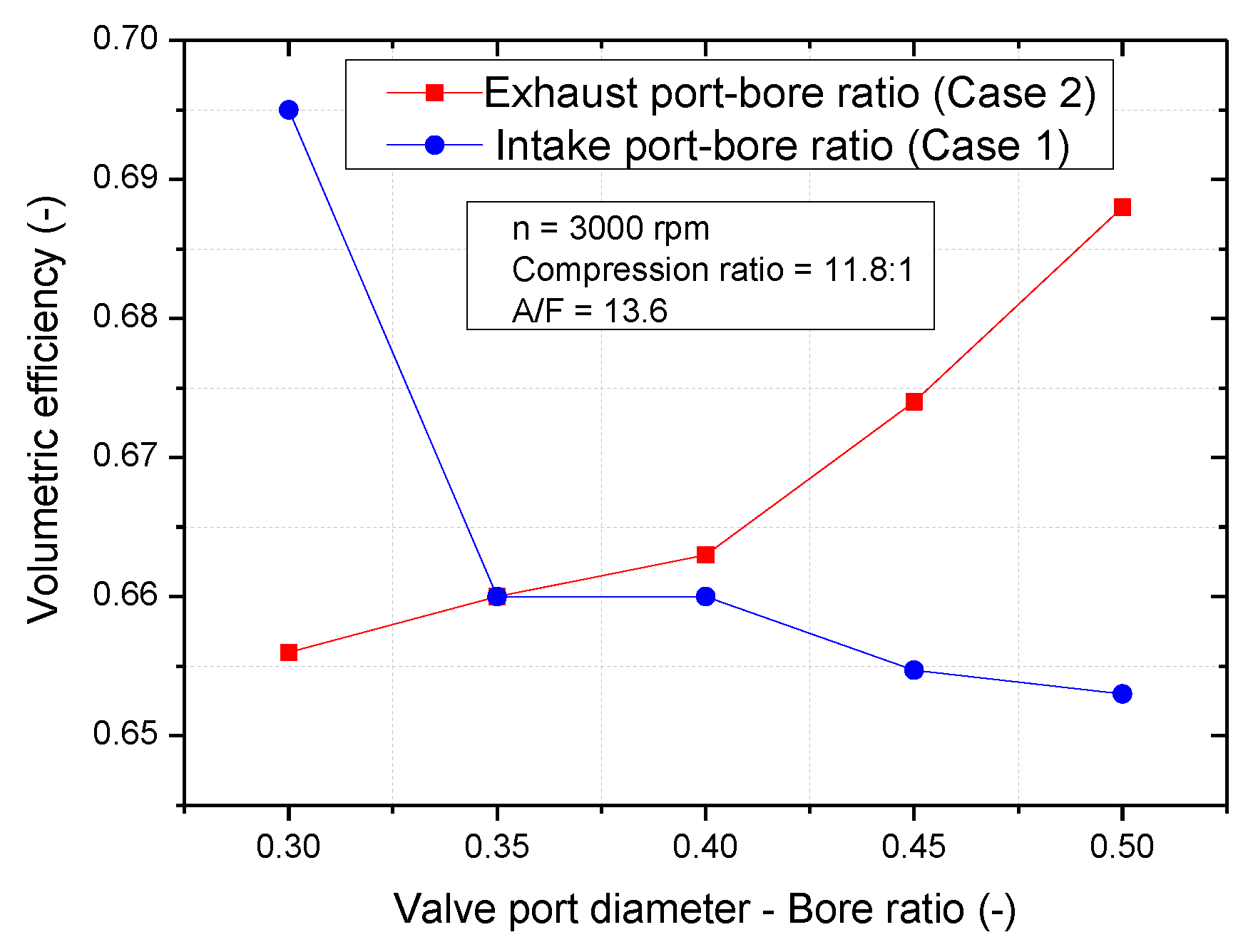
Figure 11 depicts the volumetric efficiency as a function of VPD/B ratio. A contrary effect on engine volumetric efficiency of two cases (intake port-bore ratio (case 1) and exhaust port-bore ratio (case 2)) can be observed. When the VPD/B increased from 0.3 to 0.5:
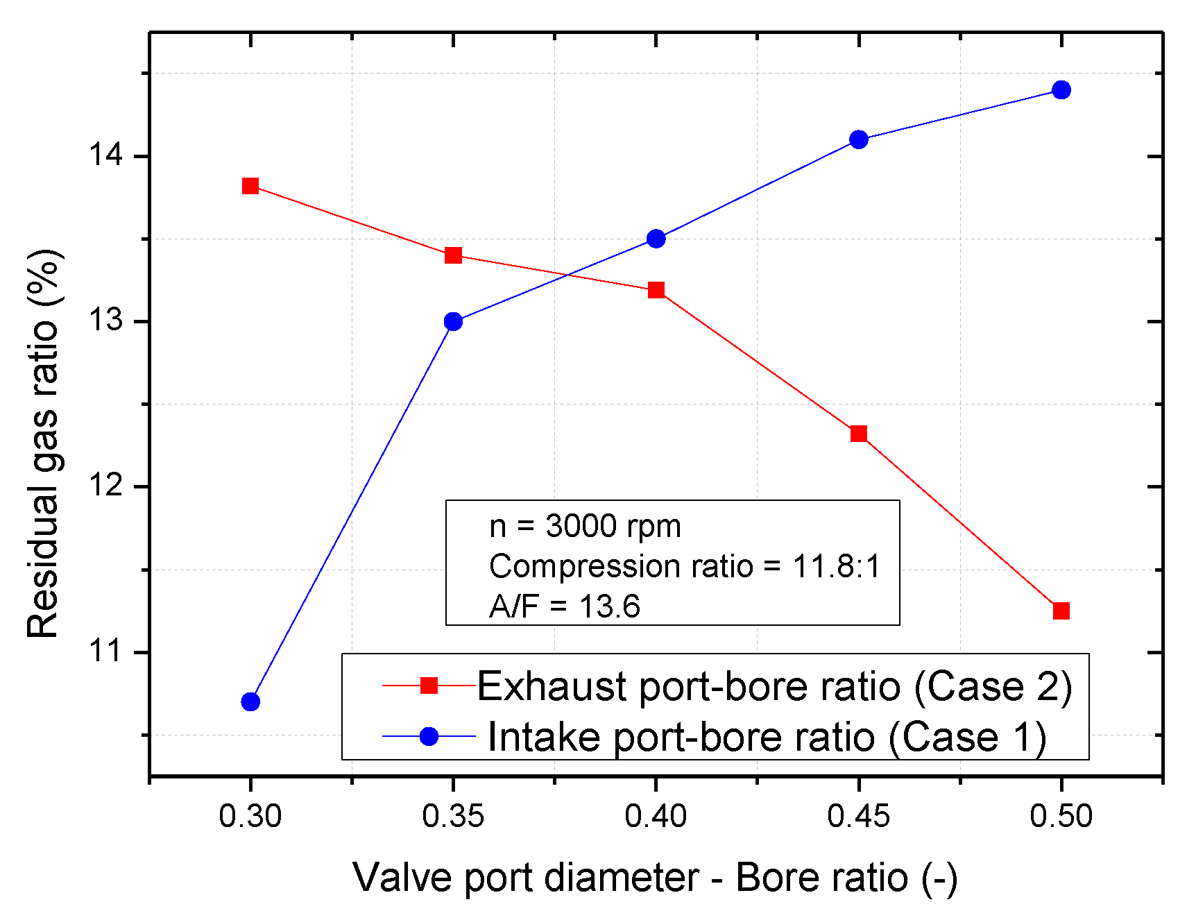
In case 1: the volumetric efficiency decreased from 0.695 to 0.653. The minimum volumetric efficiency was 0.653 at a 0.5 VPD/B and the maximum value was 0.695 at a 0.3 VPD/B. This can be explained by that at a constant engine speed, an increase of VPD/B led to decrease the swirl ratio and acceleration of air flow into the cylinder [7]. This was cause to reduce amounts of air fill into the cylinder as the subsequent effect of the intake stroke by decreasing fresh air fuel to sweep the exhausted gas out of the cylinder. This accounts for the reason why the volumetric efficiency decreases and the residual gas fraction ratio increases as the VPD/B increases (Figure 12). The residual gas fraction increased from 11 to 14%. The minimum value was 0.107% at a 0.3 VPD/B and the maximum value was 0.144% at a 0.5 VPD/B.
In case 2: the volumetric efficiency increase from 0.656 to 0.688 the minimum volumetric efficiency was 0.656 at a 0.30 VPD/B and the maximum value was 0.688 at a 0.5 VPD/B. This can be explained by that an increase of VPD/B led to decrease the reverse of exhaust gas back to the combustion chamber. This was cause to charge fresh air-fuel mixture more into the cylinder and reduce trapped residual. This accounts for the reason why the volumetric efficiency increases and the residual gas fraction ratio decreases as the VPD/B increases (Figure 12). The residual gas fraction decreased from 13.82 to 11.25%. The minimum value was 11.25% at a 0.5 VPD/B and the maximum value was 13.82% at a 0.3 VPD/B.
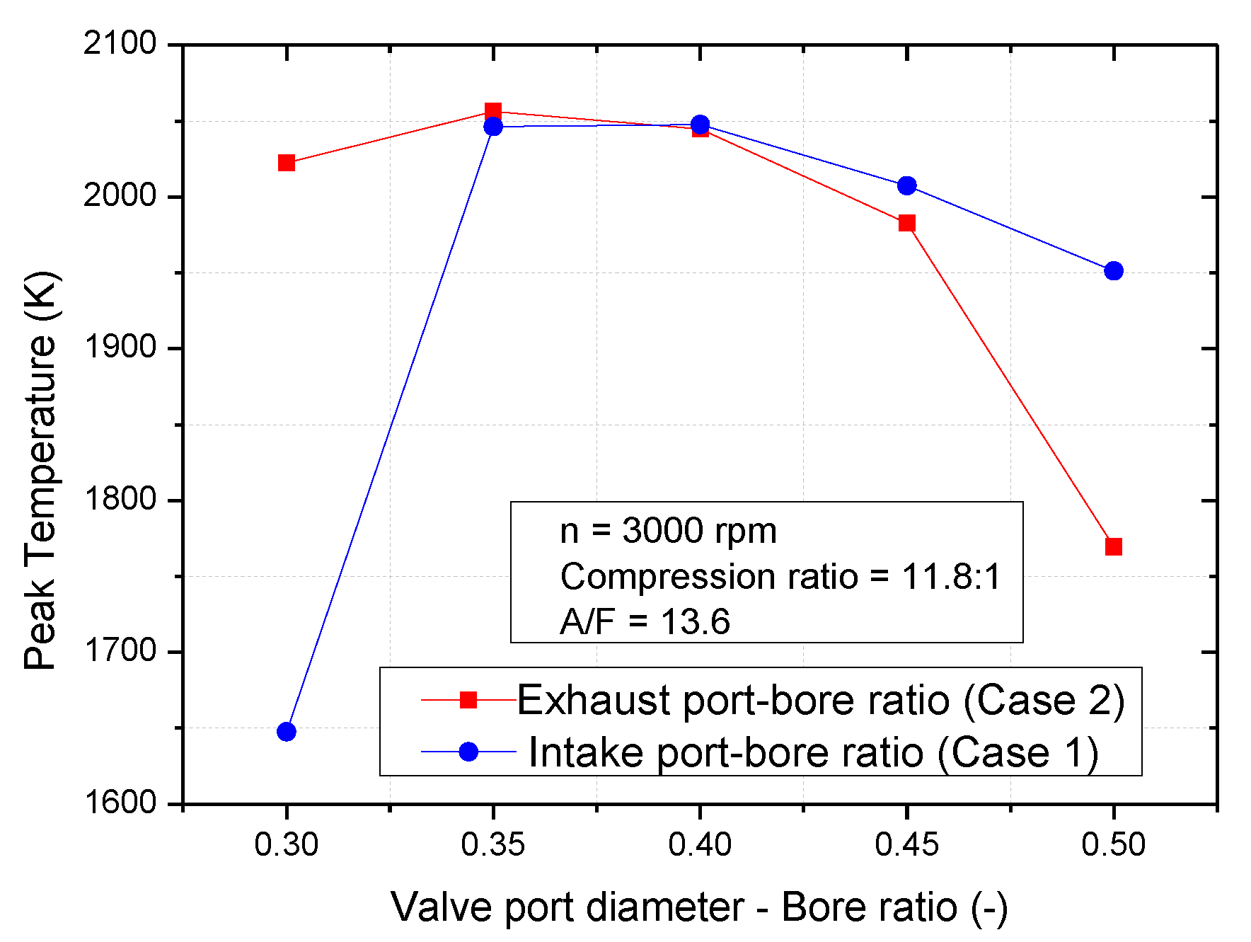
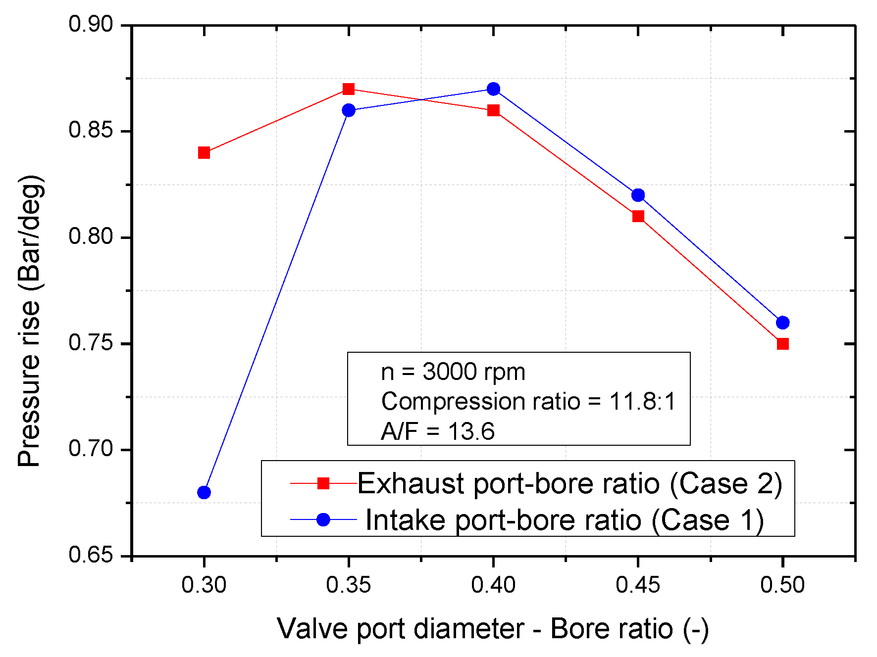
As shown in Figure 13 and Figure 14, the peak temperature and pressure increase present a similar trend in both cases. As the increase of IPD/B, the peak temperature and pressure increases after achieving a maximum value and then decreases. This is because a higher IPD/B was due to the increase or decrease in the residual gas fraction (Figure 12). A suitable an amount of high temperature exhaust gases trapped in the cylinder to raise the evaporation and homogeneity in the air-fuel mixture. The homogeneous air-fuel mixture helped the thermal energy can be released in a shorter time to improve peak temperature and pressure increase. However, when too much exhaust gas gets trapped in the combustion chamber it may restrict the fresh air-fuel mixture into the combustion chamber and due to poor combustion. This is the reason why the pressure increase and peak temperature both decreased after achieving a maximum value.
In this research:
In case 1: the maximum peak temperature and maximum peak pressure increase achieved maximum values of 2047 K and 0.87 bar, respectively at 0.4 VPD/B.
In case 2: the maximum peak temperature and maximum peak pressure increase achieved maximum values of 2056 K and 0.87 bar, respectively at 0.3 VPD/B.
In a typical spark-ignition engine, the burned reactions do not occur instantaneously. In order to increase the engine efficiency, the combustion duration is expected to be shorter and the release of the heat energy faster to decrease the heat loss. Therefore, a better homogeneous in air-fuel mixture is required to reduce combustion duration and increase the heat energy rise. The chemical energy of fuel trapped in the cylinder was released into heat energy. An amount of loss heat energy was from heat transfer, pumping loss, and energy that are not effectively released in the cylinder, but is going into the combustion products so the remaining amount energy is effective release energy. As discussed above, the residual gas fraction in combustion chamber has a big effect on homogeneous of air-fuel mixture. The influence of the residual gas fraction on the peak pressure increase, peak temperature, and effective energy can be seen though Figure 13, Figure 14 and Figure 15. As the increase of VPD/B, the effective release energy increase until a maximum value after that decrease as shown in Figure 15. The maximum value was 0.45 kJ at 0.4 VPD/B in case 1; and 0.451 kJ at 0.35 VPD/B in Case 2. From this result, we know that the engine performs optimal efficiency when the trapped residual gas fraction ratio is from 13% to 14%.
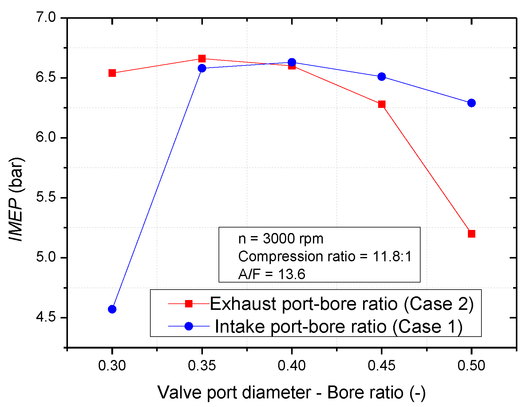
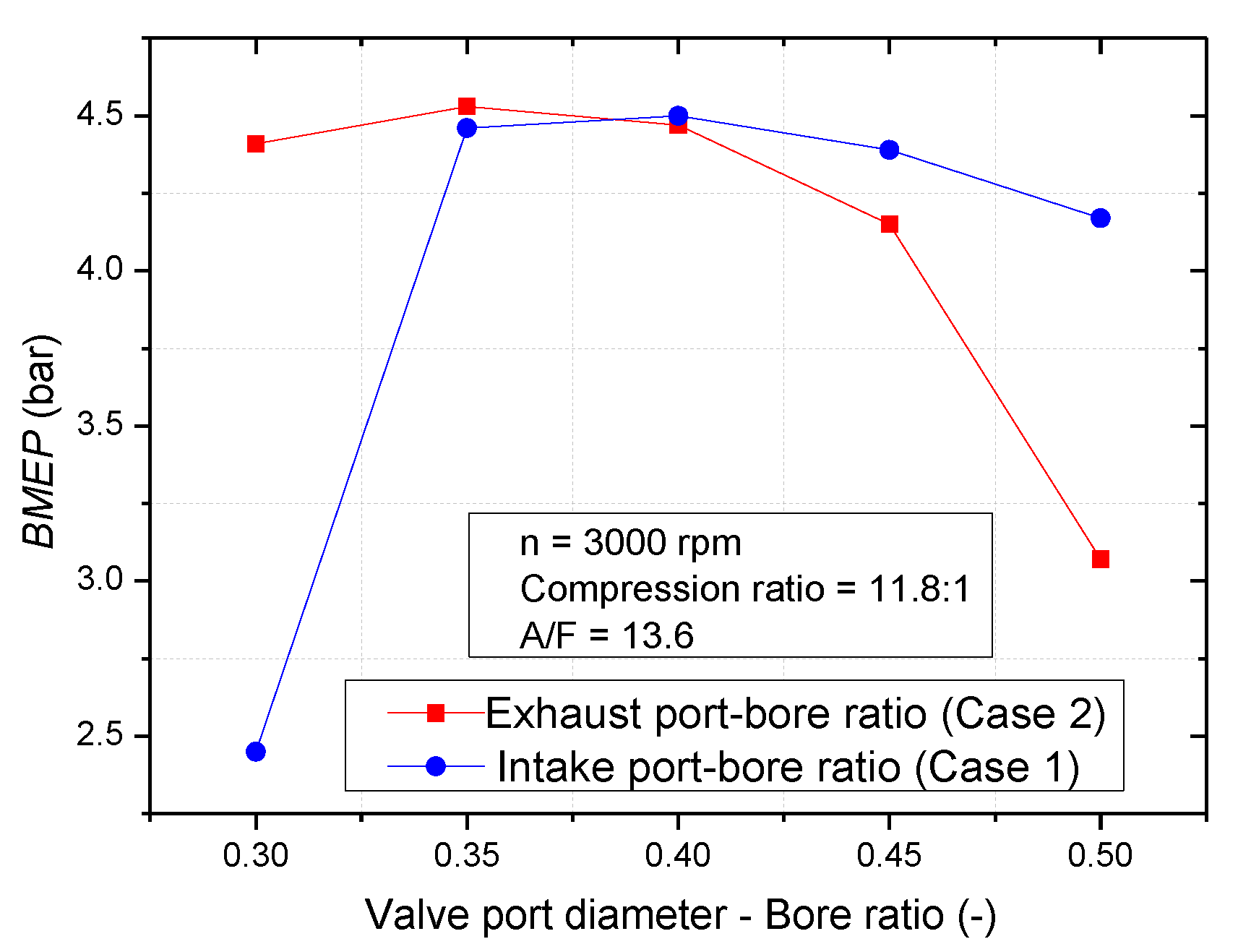
Figure 16 and Figure 17 shows the IMEP and BMEP at each VPD/B ratio. Because the cylinder pressure of power stroke has a sensitive effect on IMEP from the Equation (11), and the effective release energy effect on BMEP. Therefore, the similar trend of IMEP and pressure increase, BMEP, and effective release energy can be observed.
I M E P = 1 V D P c . d V
The IMEP and BMEP was achieved the maximum value of 6.63 bar and 4.5 bar at 0.4 VPD/B in Case 1, and in Case 2 these values are 6.66 bar, 4.53 bar, at 0.35 VPD/B, respectively.
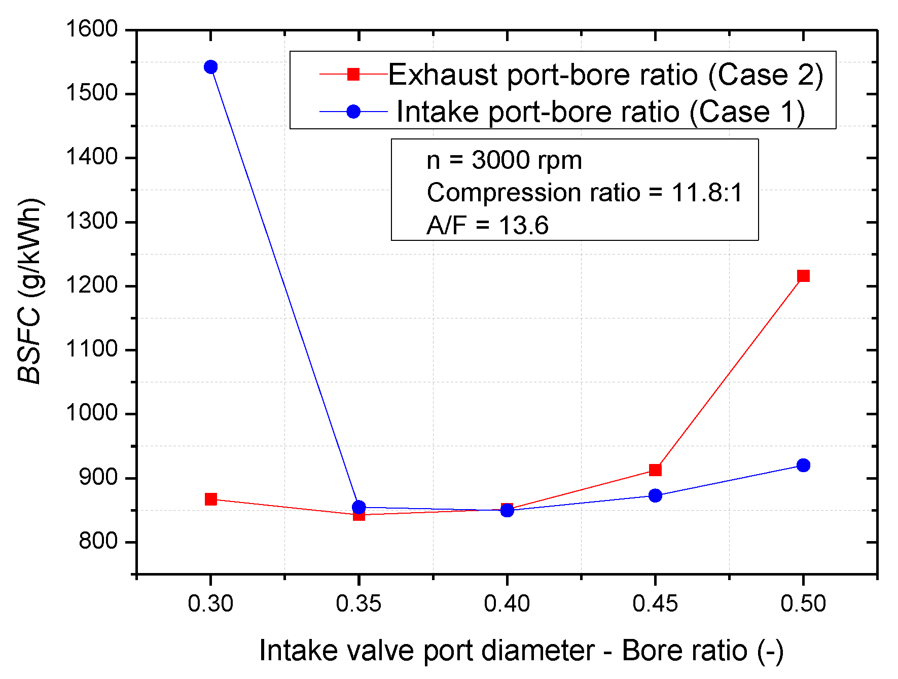
Figure 18 shows that the BSFC decrease when VPD/B ratio increase from 0.3 to 0.5. With a constant the engine speed and constant air-fuel ratio, BMEP had the greatest effect on BSFC. The influence of BMEP and BSFC to each other is shown in Equation (12)
B S F C = m a i r . n e .2.16.10 9 A F R . B M E P . V D . n
The opposite trends of BMEP and BSFC are depicted in Figure 17 and Figure 18. The minimum BSFC is 849.5 g/kWh in Case 1 and 842.8 g/kWh in Case 2.
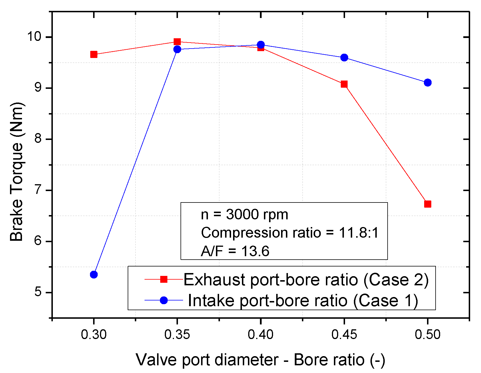
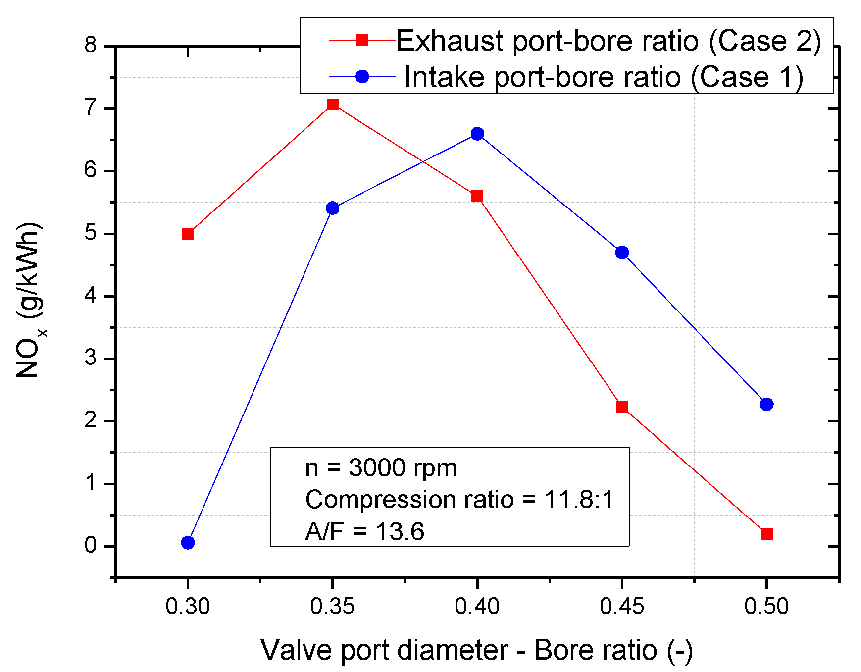
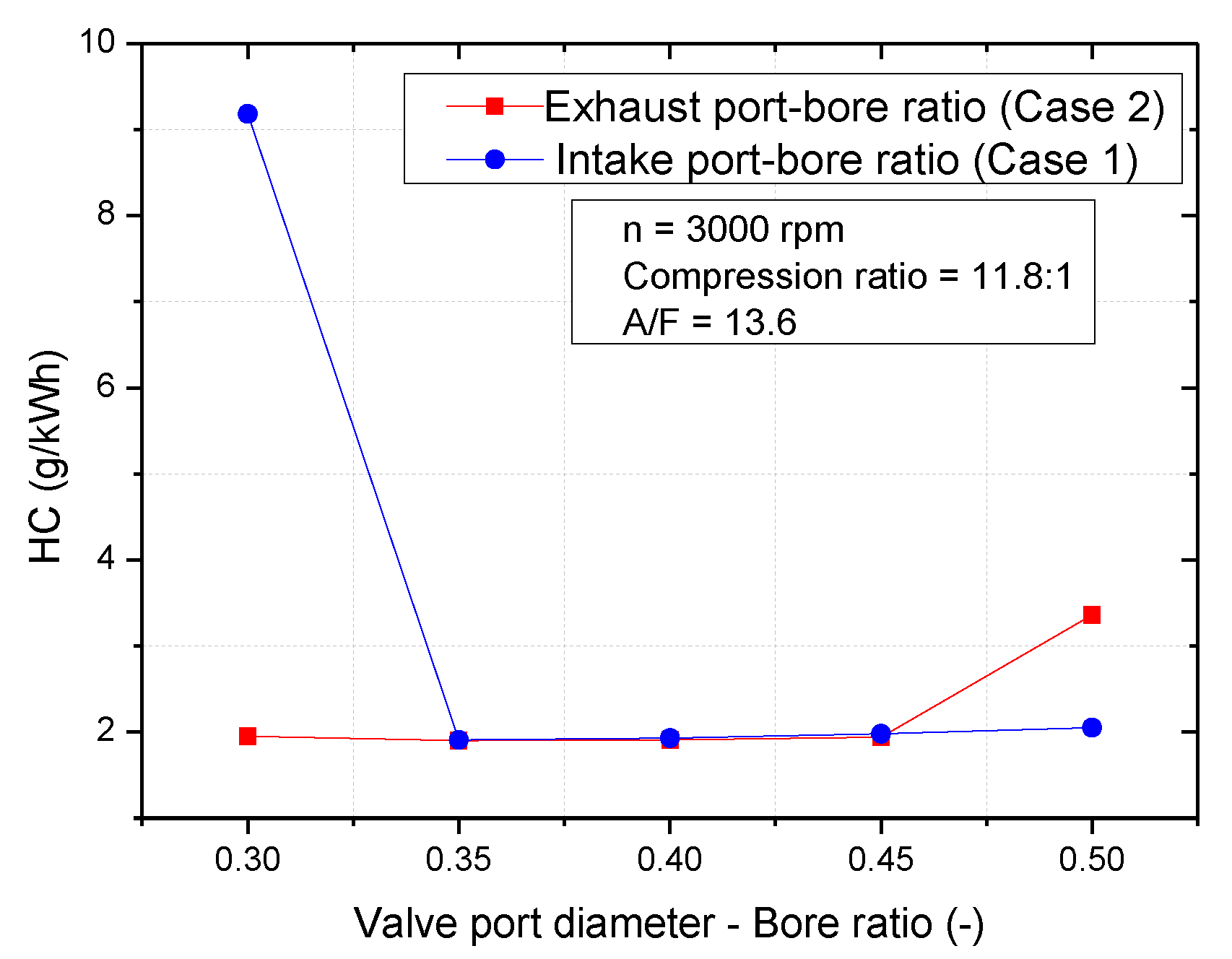
It can be seen that, at the intake, the port-bore ratio is smaller than 0.35 or exhaust port-bore ratio is bigger than 0.45. The missing firing may happen because of this band of VPD/B ratio, the BSFC value and HC emission were very high and NOx emission was nearly zero. If the intake port-bore ratio is smaller than 0.35 or the exhaust port-bore ratio is bigger than 0.45, it is not a good condition for the engine to operate.
The similar trend between BMEP and engine effective torque can be observed through Figure 17 and Figure 19. The effect of BMEP on engine effective torque is presented in Equation (13). Equation (13) shows that a higher BMEP due to an enhanced engine torque.
T e f f = B M E P . V D k c y c l e . π
Figure 19 shows the engine brake torque was achieved the maximum value of 9.85 Nm in Case 1 and 9.91 Nm in Case 2. This means the engine torque can be improved by adjusting the exhaust valve port diameter.
The peak firing temperature is a factor which has a strong effect on NOx emission, in this research, the peak firing temperature increases to a maximum value, after that decrease event VPD/B was still increasing. As a result, with both cases: the NOx shows the similar trend with peak firing temperature. Figure 20 shows the NOx emission increases until achieved a maximum value after that decrease even VPD/B was still increasing. The maximum NOx emission was 6.6 g/kWh, at 0.4 VPD/B of Case 1, and this value was 7.07 g/kWh at 0.35 VPD/B of Case 2. This result shows that the exhaust valve port-bore ratio has a more sensitive effect on NOx emission than the intake valve port-bore ratio.
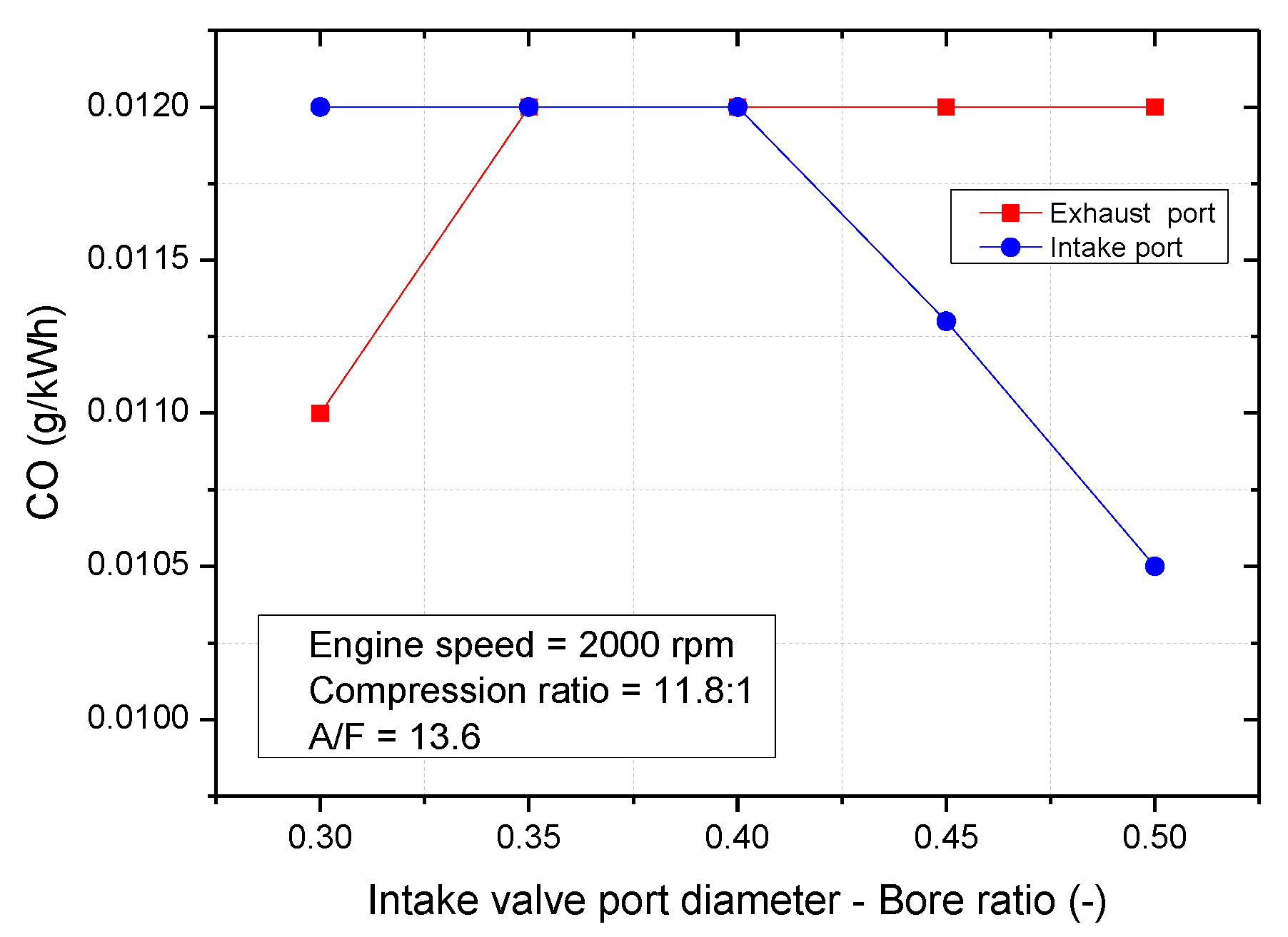
Figure 21 and Figure 22 shows that with intake port-bore ratio is smaller than 0.35 and exhaust valve port-bore ratio is bigger than 0.45. The high HC emission and low CO emission was presented. This is because the poor combustion and miss firing occurred. With a VPD/B ratio of 0.35 to 0.4 the engine has stable performance.

4. Conclusions

This paper shows a study to determine the effective release energy, peak pressure increase, and residual gas fraction of a spark-ignition engine with various VPD/B. Through our approach, the disadvantages of experimental methods were solved, producing a confident method to determine the effective energy, residual gas, peak temperature, and pressure increase.
In summation:
(1)
A lager intake port diameter causes a decrease of volumetric efficiency, while volumetric efficiency increases with a larger exhaust port diameter.
(2)
The VPD/B ratio gets large influence on residual gas fraction, effective energy, and engine emission. As the increase of VPD/B ratio of 0.3 to 0.5 the residual gas fraction increases 27.3% with larger intake port and decrease 18.6% with larger exhaust port. The engine will perform optimal efficiency when the trapped residual gas fraction is from 13 to 14%. The maximum effective release energy was 0.45 kJ at 0.4 intake port-bore ratio, and 0.451 kJ at 0.35 exhaust port-bore ratio.
(3)
The maximum peak firing temperature and peak pressure increase was 2047 K and 0.87 bar at 0.4 intake port-bore ratio. This value was 2056 K and 0.87 bar at 0.3 exhaust port-bore ratio.
(4)
The optimal effective release energy and BSFC was achieved at the same VPD/B value. When the VPD/B ranges from 0.35 to 0.4, the engine performs the maximum effective release energy and the minimum BSFC. The engine does not operate well when the VPD/B ratio value is smaller than 0.35 or bigger than 0.45 because misfiring may happen.
(5)
This result shows that the exhaust valve port-bore ratio has a more sensitive effect on NOx emission than intake valve port-bore ratio.
(6)
With the intake port-bore ratio is smaller than 0.35 and exhaust valve port-bore ratio is bigger than 0.45. The high HC emission and low CO emission were presented.

Author Contributions

N.X.K. carried out the development of the concept of the paper, performed the literature study, prepare the paper structure, aim, objectives, research question, analyzed the data, and as well as writing the paper. O.L. supervised the research, advised on the research gap and objective, proofread the paper, and guided the writing process as well as reviewing the presented concepts and outcomes. All authors have read and agreed to the published version of the manuscript.

Funding

This research was financially supported by the Energy Technology Development Project of the Korea Energy Technology Evaluation and Planning (20182010106370, Demonstration Research Project of Clean Fuel DME Engine for Fine Dust Reduction), Republic of Korea.

Conflicts of Interest

The authors declare no conflict of interest.

Nomenclature

BDCBottom dead center
TDCTop dead center
BTDCBefore top dead center
ATDCAfter top dead center
BSFCBrake specific fuel consumption (g/KWh)
BMEPBrake mean effective pressure (Bar)
IMEPIndicated mean effective pressure (Bar)
HCHydrocarbon
CACrank angle (deg)
VPD/BValve port diameter-bore ratio (-)
TeffEngine effective torque (Nm)
KcylceSimulation cycle parameter (cycles)
QhThe total fuel heat input (W)
αThe crank angle (deg)
α0The start of combustion (deg)
α c The combustion duration (deg)
mThe shape parameter (-)
aThe Vibe parameter (-)
QTThe heat lost to the wall (W/m2)
AThe total surface area of the cylinder head, piston
qcoeffThe heat transfer coefficient (W/m2 K)
TcThe combustion gas temperature (K)
TwThe wall temperature of the cylinder (K)
d m d t The air mass flow rate
AeffThe effective flow area (-)
P1The upstream stagnation pressure (Pa)
T1Upstream stagnation temperature (K)
RGas constant (J/kg.K)
P2Downstream static pressure (Pa)
KRatio of specific heat
CpDenotes post processing multiplier
CKDenotes kinetic multiplier
riDemotes reaction rates (mole/cm3s)
mHCMass of unburned charge in the crevices (kg)
PcCylinder pressure (Pa)
VcreviceTotal crevice volume (m3)
MUnburned molecular weight (kg/kmol)
TpistonPiston temperature (K)
θCam angle (deg)
CdCoefficient of discharge
QMeasured volume flow rate (m3/sec)
AseatInner seat area (m2)
AvOrifice are between valve head and seat (m2)
EGRExhaust gas recirculation
VDDisplaced volume (m3)
CfFlow coefficient
V0Velocity dead (m/s)
DseatIntake valve seat diameter (m)
LValve lift (m)
φValve seat angle (deg)
nEngine speed (rpm)

References

  1. Cinar, C.; Uyumaz, A.; Solmaz, H.; Topgul, T. Effects of valve lift on the combustion and emis-sions of a HCCI gasoline engine. Energy Convers. Manag. 2015, 94, 159–168. [Google Scholar] [CrossRef]
  2. Suhaimi, S.; Mamat1, R.; Abdullah, N.R. Investigation of the effects of inlet system configuration on the airflow characteristics. IOP Conf. Ser. Mater. Sci. Eng. 2013, 50. [Google Scholar] [CrossRef] [Green Version]
  3. Shi, L.; Shu, G.; Tian, H.; Deng, S. A review of modified Organic Rankine cycles (ORCs) for internal combustion engine waste heat recovery (ICE-WHR). Renew. Sustain. Energy Rev. 2018, 92, 95–110. [Google Scholar] [CrossRef]
  4. Jung, D.; Iida, N. An investigation of multiple spark discharge using multi-coil ignition system for improving thermal efficiency of lean SI engine operation. Appl. Energy 2018, 212, 322–332. [Google Scholar] [CrossRef]
  5. Gandyk, M.; Tkaczyk, M.; Sitnik, L.J.; Uzuntonev, T. Combustion engine intake port design analysis. Mach. Technol. Mater. 2015, 9, 29–31. [Google Scholar]
  6. Regueiro, J.F.; Korn, S.J. Geometric papameters of four-valve cylinder heads and their relationship to combustion and engine full load performance. SAE Trans. 1994, 103, 184–198. [Google Scholar]
  7. Zhang, Y.; Zhao, H.; Xie, H.; He, B.-Q. Variable-valve-actuation enabled high efficiency gasoline engine. J. Auto-Mobile Eng. 2010, 224, 1081–1095. [Google Scholar] [CrossRef]
  8. Ghazal, O.H.; Najjar, Y.S.; AL-Khishali, K.J. Effect of Varying Inlet Valve Throat Diameter at Different IVO, IVC, and OVERLAP Angles on SI Engine Performance. In Proceedings of the World Congress on Engineering 2011 (WCE 2011), London, UK, 6–8 July 2011. [Google Scholar]
  9. Raghu, M.M.; Pramod, S. Influence of intake port design on diesel engine air motion characteristics. Indian J. Eng. Mater. Sci. 1999, 6, 53–58. [Google Scholar]
  10. Yasar, A.; Sahin, B.; Akilli, H.; Aydin, K. Effect of inlet port on the flow in the cylinder of an internal combustion engine. Proc. Inst. Mech. Eng. Part C J. Mech. Eng. 2006, 220, 72–83. [Google Scholar]
  11. Qi, Y.L.; Dong, L.C.; Liu, H.; Puzinauskas, P.V.; Midkiff, K.C. Optimization of intake port design for SI engine. Int. J. Automot. Technol. 2012, 13, 861–872. [Google Scholar] [CrossRef]
  12. Latheesh, V.M.; Parthasarathy, P.; Baskaran, V.; Karthikeyan, S. Design and CFD analysis of intake port and exhaust port for a 4 valve cylinder head engine. IOP Conf. Ser. Mater. Sci. Eng. 2018, 310. [Google Scholar] [CrossRef]
  13. Khoa, N.X.; Lim, O. The effects of combustion duration on residual gas, effective release energy, engine power and engine emissions characteristics of the motorcycle engine. Appl. Energy 2019, 248, 54–63. [Google Scholar] [CrossRef]
  14. Khoa, N.X.; Lim, O. Effective release energy, residual gas, and engine emission characteristics of a V-twin engine with various exhaust valve closing timings. J. Mech. Eng. 2020, 34, 477–488. [Google Scholar] [CrossRef]
  15. Petranović, Z.; Sjerić, M.; Taritaš, I.; Vujanović, M.; Kozarac, D. Study of advanced en-gine operating strategies on a turbocharged diesel engine by using coupled numerical approaches. Energy Convers. Manag. 2018, 171, 1–11. [Google Scholar]
  16. Teo, A.E.; Chiong, M.S.; Yang, M.; Romagnoli, A.; Martinez-Botas, R.F.; Rajoo, S. Performance evaluation of low-pressure turbine, turbo-compounding and air-Brayton cycle as engine waste heat recovery method. J. Energy 2019, 166, 895–907. [Google Scholar] [CrossRef]
  17. Rubio, J.A.P.; V-García, F.; Grau, J.H.; Cámara, J.M.; Hernandez, D.A. Marine diesel engine failure simulator based on thermodynamic model. Appl. Therm. Eng. 2018, 144, 982–995. [Google Scholar] [CrossRef]
  18. Melaika, M.; Rimkus, A.; Vipartas, T. Air Restrictor and Turbocharger Influence for the Formula Student Engine Performance. Procedia Eng. 2017, 187, 402–407. [Google Scholar] [CrossRef]
  19. Praptijanto, A.; Muharam, A.; Nur, A.; Putrasari, Y. Effect of ethanol percentage for diesel engine performance using virtual engine simulation tool. Energy Procedia 2015, 68, 345–354. [Google Scholar] [CrossRef] [Green Version]
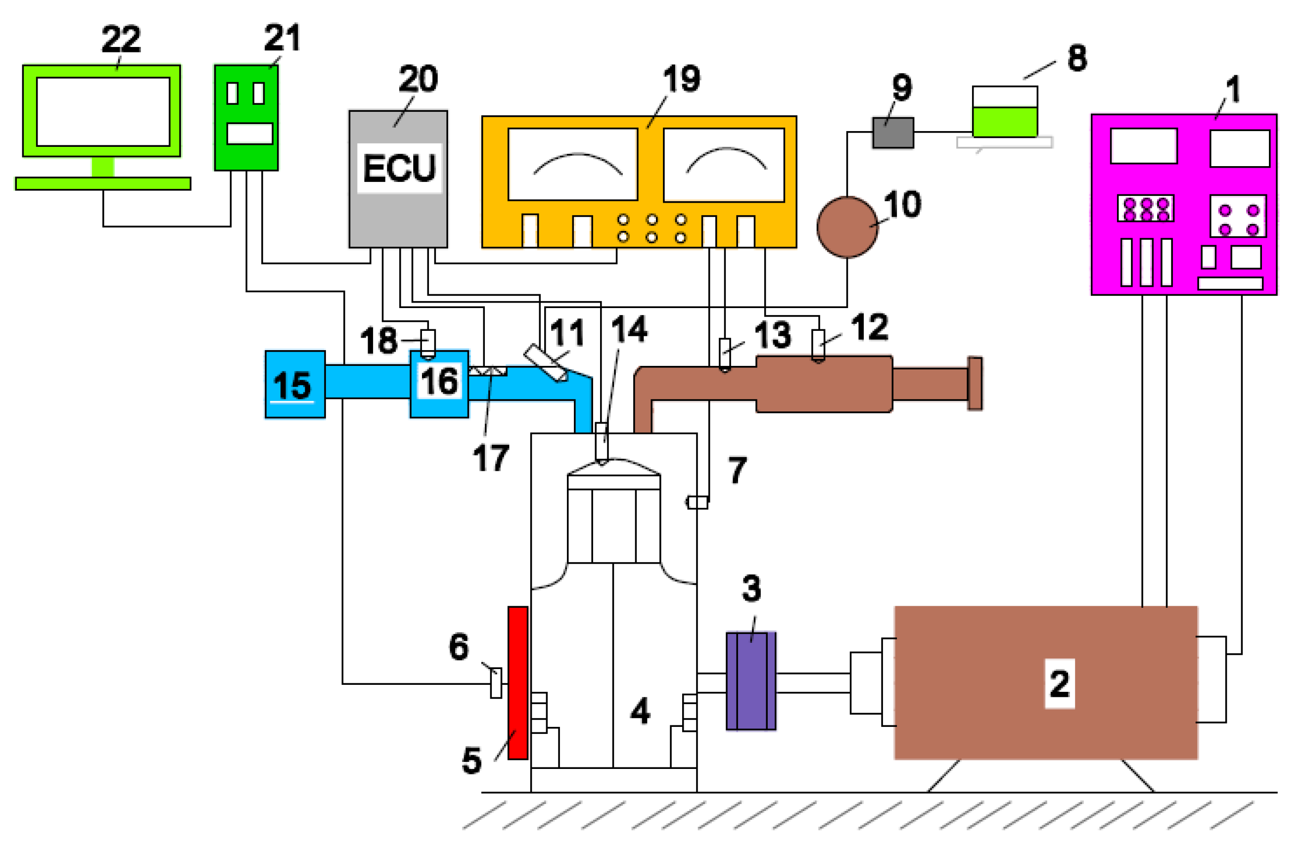
Figure 1. Schematic of the V-twin engine experimental setup.
Energies 13 01330 g001
Figure 2. Experimental engine setup system.
Energies 13 01330 g002
Figure 3. Simulation model.
Energies 13 01330 g003
Figure 4. Ignition timing following engine speed.
Energies 13 01330 g004
Figure 5. Air mass flow following engine speed.
Energies 13 01330 g005
Figure 6. Peak temperature following engine speed.
Energies 13 01330 g006
Figure 7. Peak pressure increase following engine speed.
Energies 13 01330 g007
Figure 8. Brake torque following engine speed.
Energies 13 01330 g008
Figure 9. NOx emission following engine speed.
Energies 13 01330 g009
Figure 10. HC emission following engine speed.
Energies 13 01330 g010
Figure 11. Volumetric efficiency versus VPD/B.
Energies 13 01330 g011
Figure 12. Residual gas fraction versus VPD/B.
Energies 13 01330 g012
Figure 13. Peak firing temperature versus VPD/B.
Energies 13 01330 g013
Figure 14. Pressure increase versus VPD/B.
Energies 13 01330 g014
Figure 15. Effective release energy versus VPD/B.
Energies 13 01330 g015
Figure 16. IMEP versus VPD/B.
Energies 13 01330 g016
Figure 17. BMEP versus VPD/B.
Energies 13 01330 g017
Figure 18. BSFC versus VPD/B.
Energies 13 01330 g018
Figure 19. Brake torque versus VPD/B.
Energies 13 01330 g019
Figure 20. NOx emission versus VPD/B.
Energies 13 01330 g020
Figure 21. HC emission versus VPD/B.
Energies 13 01330 g021
Figure 22. CO emission versus VPD/B.
Energies 13 01330 g022
Table 1. Specifications of the researching engine
ParameterUnitValue
Model-Four stroke, Spark ignition
Number of cylinder-2
Compression ratio-11.8:1
Boremm57
Strokemm53.8
Connecting rodmm107.9
Intake valve-Number: 2 valvesDiameter: 22 mm, valve lift: 6.5 mm; opening: 40 deg BTDC, closing: 200 deg ATDC.
Exhaust valve-Number: 2 valves Diameter: 22 mm, valve lift: 6.5 mm; opening time: 230 deg ATDC, closing: 30 deg ATDC.
Cooling system-Air cooled
Table 2. VPD/B ratio of two cases.
VPD/B ratio0.30.350.40.450.5
Intake and exhaust port diameter (mm)17.1202225.728.5