Article

Improvement of Flow Distribution by New Inlet Header Configuration with Splitter Plates for Plate-Fin Heat Exchanger

1
Key Laboratory of E&M, Zhejiang University of Technology, Hangzhou 310014, China
2
State Key Laboratory of Fluid Power and Mechatronic Systems, Zhejiang University, Hangzhou 310027, China
*
Author to whom correspondence should be addressed.
Energies 2020, 13(6), 1323; https://doi.org/10.3390/en13061323
Submission received: 15 February 2020 / Revised: 4 March 2020 / Accepted: 9 March 2020 / Published: 12 March 2020

Abstract

:
The pressure drop increases along with the decrease in the flow maldistribution in the two-stage distributing inlet headers of a plate-fin heat exchanger. To solve this issue, we proposed a new inlet header configuration with splitter plates to decrease the flow maldistribution and pressure drop simultaneously. We used computational fluid dynamic technology to analyze the flow properties in the inlet header configuration and calculated the flow maldistribution degree of the outlet channels and the pressure drop in the inlet header. We performed a sensitivity analysis between the structural parameters, the flow maldistribution degree, and the pressure drop. We determined the optimum values of the structural parameters (the construction of transition duct, the number of splitter plates, the inclined angle of outermost plates, the height of splitter plates, the height of inlet header, etc.), and acquired the optimum configuration of the improved inlet header. Compared with the traditional inlet header, the flow maldistribution degree and pressure drop decreased by 91.5% and 40.9%, respectively, using the proposed improved inlet header with splitter plates, which performed better than the conventional two-stage distribution inlet header.

1. Introduction

Multi-stream plate-fin heat exchangers (MPFHEs) are widely used in many applications, including as air separation units, the aerospace industry, in buildings, and for cryogenic liquefaction due to a high heat transfer efficiency, high heat transfer surface-area-to-volume ratio, and low weight [1,2]. MPFHEs are constructed of an inlet header, fin channels, and an outlet header. The hot and cold fluids are assumed to be uniformly distributed among different fin channels in many thermal design methodologies for MPFHEs, such as the logarithmic mean temperature difference (LMTD) method [3] and the effectiveness-number of transfer units (ε-NTU) method [4]. However, it is impossible to distribute these fluids to different channels uniformly in the inlet header, and uneven flow commonly exists in the actual operation conditions.
The reasons for flow maldistribution can be divided into geometry design features and variational operation conditions. Geometry design features include the improper design of the header, manufacturing tolerances, and structural differences among the different channels. The variational operation conditions include the flow velocity changes along the headers, the fluid viscosity, and the multiphase flow [5,6].
Flow maldistribution in the inlet header and its effects on the thermal performances were investigated using theoretical analysis, computational fluid dynamic (CFD) simulations, and experimental testing technologies in the past few decades [7,8]. Lalot [9] calculated the outlet velocity ratio to represent the flow maldistribution, and the results indicated that the gross flow maldistribution led to a loss of effectiveness of about 7% for counterflow heat exchangers and up to 25% for crossflow exchangers. Rao [10] presented an experimental investigation analyzing the influence of flow maldistribution on the pressure drop of heat exchangers, the results indicated that maldistribution was more severe in Z-type plate heat exchangers compared to U-type plate heat exchangers. Chin [11] analyzed the influences of four statistical moments (mean, standard deviation, skew and kurtosis) of inlet flow maldistribution on the thermal performance of MPFHE, results indicated that the mean and standard deviation had the highest effects on the performance degradation, whereas kurtosis had no significant effect. Salehi [12] determined that the optimum baffle location in the inlet header was the middle distance between inlet ducts and heat transfer plates, which could improve the flow maldistribution in the inlet header and effectiveness of heat exchanger with input Reynolds numbers of 250–3000 Niroomand [13] developed a quasi-three-dimensional model of MPFHE which considered the influences of inlet flow maldistribution and transverse heat conduction simultaneously.
After quantitatively determining the flow maldistribution in the inlet header, some attempts were made to decrease the deteriorating influences on the thermal performance of MPFHEs. These can be classified into two types: (1) Structural optimization of the inlet header to decrease inlet flow maldistribution; and (2) partial thermal compensation in the fin channel region. For the thermal compensation of flow maldistribution, Jung [14] proposed the transverse bypass structure among the channels of hot streams or cold streams, and the improved thermal effect was quantitatively analyzed and verified in a practical heat exchanger. Peng [15] decreased the thermal deterioration influence of inlet flow maldistribution through coordinate optimization design of passage arrangement and inlet mass flow rates.
Although thermal performances can be partially compensated using improvements of fin channels and passage arrangement, the improvement effectiveness of thermal performances is limited as there are serious flow maldistribution upon entering fin channels, which cannot be eliminated in fin channels. Structural optimization of inlet header is the main technology used to improve the thermal performances. Jiao [16] put forward the concept of second header to improve the flow maldistribution, then Wen [17] proposed a second header configuration with a baffle plate containing small holes to improve flow maldistribution. Ismail [18] proposed an improved baffle plate with varying dimensions of arranged holes, which could decrease the pressure drop compared with traditional baffle plates with uniform holes. Yaïci [19] improved the geometrical parameters, such as longitudinal tube pitches, transversal tube pitches, and fin pitches, to decrease flow maldistribution. Yang [20] proposed an improved quasi-S-type header configuration, which could reduce the maldistribution parameters by 89.9%–91.8% compared with a traditional inlet header in typical plate-fin heat exchanger. Tu [21] investigated a modifying inlet nozzle configuration with porous baffles, which could decrease the flow maldistribution by 52.0% for the gas phase and 47.5% for the liquid phase.
Although many modified inlet header configurations have been proposed and these modifications improved the flow maldistribution, the pressure drop and flow resistance of the heat exchanger were also increased. To solve these issues, we proposed a new inlet header configuration with splitter plates to decrease the flow maldistribution and pressure drop simultaneously. The novelty of this work is its presentation of a new inlet header configuration with splitter plates which can decrease the flow maldistribution and pressure drop simultaneously. The results of this work can be used to guide the structural design of inlet header for plate-fin heat exchanger. The paper is organized as follows: Section 2 describes the proposed new inlet header configuration with splitter plates, and the CFD calculation model was established to analyze the flow distribution and pressure drop of the improved inlet header. In Section 3, we detailed the sensitivity analysis between geometry parameters, flow maldistribution degree, and pressure drop, and determined the optimum structural configuration of improved inlet header. In Section 4, we compared the flow maldistribution and pressure drop between the proposed inlet header and two traditional inlet headers to verify the effectiveness of the proposed configuration. Our conclusions are summarized in Section 5.

2. Physical and Mathematical Model of Inlet Header

2.1. Traditional Physical Models of Inlet Header

The flow maldistribution of MPFHE is mainly related to the construction of inlet header. A schematic diagram of the conventional header (denoted as Configuration A) is illustrated in Figure 1, in which the length L and radius R of the inlet header are 452 mm and 77 mm, respectively. The fluid flows from the small inlet flow pipe with diameter D = 100 mm into the header straightforwardly, and then flows to fin channels through multiple outlet channels of the inlet header. There is serious flow maldistribution using the conventional header (Configuration A), where the outlet velocity and mass flow rates in the middle region are higher than both sides at the plane of outlet channels. Therefore, an improved inlet header with splayed perforated wing panels (denoted as Configuration B) was proposed by Yang [22], as illustrated in Figure 2. The fluid flows through the small holes on the wing panels, which can decrease the velocity in the central region and increase velocities at both edges of the header, thereby improving the flow distribution.

2.2. Improved Inlet Header

Compared with the conventional inlet header (Configuration A), the flow distribution and the total heat transfer rate can be improved using an inlet header with Configuration B or using other second headers with punched panels. However, the pressure drop is also increased, and it is difficult to determine the optimum locations and the diameters of holes on the wing panels. Especially in multiple operation conditions, the quantitative calculation regulations for determining the hole structures are lacking, which restricts the application of these two-stage distributing inlet headers. The pressure drop of Configuration B is high due to the flow resistance at the panels. The velocity differences at two sides of the panels are very high. To decrease the blocking effect of the panels, an improved inlet header with splitter plates (Configuration C) was proposed, which is illustrated in Figure 3a. The fluid was redistributed by multiple splitter plates with the same height and different inclined angles in the flowing region of inlet header. The spaces between adjacent splitter plates in the central region of header were smaller than those at both edges. The main structure parameters of the proposed improved header contained the number of splitter plates n, the height of splitter plates h, the inclined angle of the outermost plates α , and the height of inlet header H, which are shown in Figure 3b. Using the improved inlet header, the mass flow rates at the edges were enhanced and the mass flow rates in the central region were reduced, which reduced the flow maldistribution. Compared with punched baffles, the flow resistance was lower using splitter plates, as they decreased the pressure drop of heat exchanger.

2.3. CFD Analysis

The structure of the improved inlet header was constructed in Solidworks, and the flow simulation was evaluated using Fluent software.
The inlet velocity of fluid was determined, and the total area of outlet channels was the same. Therefore, the mean values of the mass flow rates of outlet channels were the same, and the flow maldistribution was represented using the dimensional flow maldistribution degree S (as demonstrated in previous researches [23,24]) in Equation (1), which is the standard deviation of mass flow rates at the outlet channels of the header. The pressure drop Δ p was calculated using Equation (2) based on the inlet pressure p i n and outlet pressure p o u t calculated in Fluent software.
S = 1 n 1 i = 1 n ( m ˙ i m ¯ ) 2 ,
Δ p = p i n p o u t ,
where n = 11 is the number of outlet channels of inlet header entering the fin channel region, m ˙ i is the calculated mass flow rates of i-th outlet channel, and m ¯ is the mean of mass flow rates of all channels.
In the following flow simulation analysis, the inlet duct and outlet channels were the same as the header in Reference [22]. The conservation equations of mass, momentum, and energy were solved using the finite volume method with the SIMPLE pressure-velocity coupling algorithm based on the standard k ε model. Boundary conditions contained the inlet velocity and temperature of air, which were 14.6 m/s and 300 K. The dissipation rate of turbulent was 3.8%, and the walls were adiabatic with no slips. The convergent condition was specified as when the absolute residuals were lower than 10−5. The grid number of the computational domain had a very important influence on the accuracy of results. The accuracy can be improved with an increase in grid number, while the computational complexity and computational time were also increased. To determine the optimum grid number, a series of grid independence tests were implemented to determine the optimum grid number. The total number of grid and corresponding calculated flow maldistribution degree under different maximum sizes of grid cells are shown in Figure 4.
With the decrease of the maximum size of the grid cell, the calculation accuracy of the flow maldistribution degree was increased, but the number of grid cells and the computational complexity were also increased. When the size of grid cells decreased to 0.5 mm, the accuracy did not greatly improve. When the size decreased from 0.5 mm to 0.25 mm, the number of grid cells increased from 123,079 to 467,874 and the computational complexity increased by fourfold. However, the accuracy only increased by 0.1%. Therefore, the grid with a maximum cell size of 0.5 mm was the optimum, which had a high computational accuracy with a low computational time. In the following section, the maximum size of grid cells was specified as 0.5 mm in the CFD simulation analysis of different size structures of inlet headers. To validate the effectiveness of the present CFD simulation model, the outlet velocity distribution of conventional header (Configuration A) from Reference [17] was calculated. The results calculated by the presented CFD simulation model and PIV test in Reference [17] were compared in Figure 5. The variation treads of velocity of outlet channels calculated by the CFD simulation model are in good agreement with the PIV test results, and the root-mean-square error of the outlet velocities was 9.12%. Therefore, the proposed CFD model was effective.

3. Optimization Design of Structural Parameters for Improved Inlet Header

The influences of the transition duct between inlet duct and header core, number of splitter plates n, the inclined angle of the outermost plates α , the height of splitter plates h, and the height of inlet header H on flow maldistribution degree S and pressure drop Δ p were analyzed, and the optimal configuration of improve inlet header with splitter plates were determined.

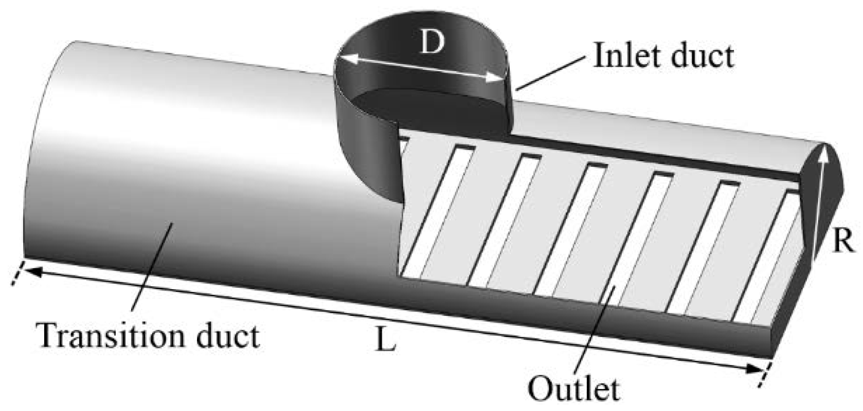
3.1. Transition Duct Construction Between Inlet Duct and Header

There were multiple types of transition duct constructions between the inlet duct and header in the existing configurations of the inlet header. Three typical transition ducts were compared in the improved inlet header, including a direct transition duct (Figure 6a), triangle transition duct (Figure 6b) and quasi-parabola transition duct (Figure 6c).
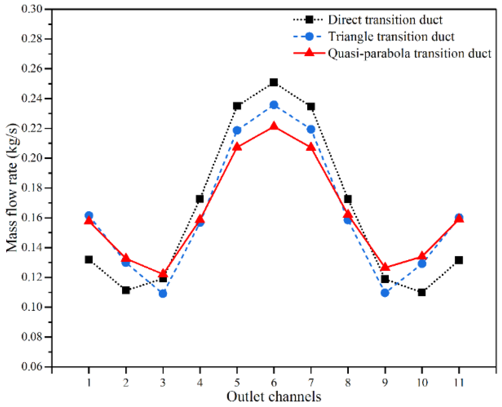
Figure 7 shows the velocity distribution in the inlet header with different transition ducts. The mass flow rates at outlet channels under the three transition ducts are shown in Figure 8. There was a mutation between the equivalent diameters of the direct transition duct and the outlet channels of the header, two reverse flow regions were formed, and the flow maldistribution degree reached 0.0543 kg/s. The reverse flows can be decreased using the triangle transition duct and quasi-parabola transition ducts. Compared with the triangle transition duct, the velocity gradient was smoother, and the velocity mutation was less using the quasi-parabola transition duct. Results indicate that the difference between the maximum and minimum mass flow rates was decreased and the flow maldistribution degree of quasi-parabola transition duct was 0.0348 kg/s, which was 78.6% of the flow distribution degree in the triangle transition duct. Therefore, the quasi-parabola transition duct was applied in the following improved inlet header.

3.2. Number of Splitter Plates n

The number of splitter plates n can be an odd number or even number. If n is an odd number, one splitter plate is installed at the center position facing the inlet duct, and the other splitter plates are symmetrically installed on both sides of the central plate. If n is an even number, all splitter plates are symmetrically installed in the inlet header. The velocity distribution in the header with n = 8 and n = 9 are shown in Figure 9. With n = 8 , high velocity differences were observed at the central splitter plate, which increased the flow maldistribution and pressure drop. Therefore, the flow maldistribution was lower using an odd number of splitter plates.
The mass flow rates at outlet channels under different odd numbers n = 3, 5, 7, and 9 of splitter plates were calculated and listed in Figure 10. The corresponding flow maldistribution degrees and pressure drops are shown in Figure 11. When the number of splitter plates increased from 3 to 5, the flow maldistribution degree S increased from 0.0354 kg/s to 0.0385 kg/s because the air flow velocity in the central region was suddenly increased. As the number of splitter plates increased from 5 to 9, the flow maldistribution degrees S were 0.0385 kg/s, 0.01005 kg/s, and 0.0059 kg/s, respectively. The flow maldistribution degrees were decreased because the air flow velocities in the direction of length L were increased, which can decrease the flow maldistribution. If n was further increased to 11 or more, the distance between adjacent splitter plates will be too small to manufacture due to the size limitations of inlet header. Therefore, the optimum number of splitter plates was n = 9 when considering the influences of flow maldistribution, pressure drop, and structural constraints simultaneously.

3.3. Inclined Angle of Outermost Splitter Plates α

The inclined angle of the outermost splitter plates α has an important influence on the angles of other splitter plates and the air flow condition in the header. Therefore, the air flow simulations with different α [ 46 , 55 ] were implemented in Fluent, and the other parameters were determined as H = 100 mm, h = 30 mm, and n = 9. The flow maldistribution degree S and pressure drop Δ p are shown in Figure 12. The pressure drop was decreased as the increase of inclined angle α . As inclined angle value α increased, the transverse flow effect was improved, the mass flow rates at both sides of outlet channels were increased and the flow maldistribution degree S was decreased. However, when the inclined angle value α was too high, the transverse flow effect was very serious, the mass flow rates in middle region of outlet channels were low, and the flow maldistribution degree S was also increased. The minimum value of S was 0.005876 kg/s at α = 50 and α = 51 . The pressure drop Δ p at α = 51 was 104.9 Pa, which was smaller than 108.6 Pa at α = 50 . Therefore, the optimum inclined angle of the outermost splitter plate was α = 51 .

3.4. Inlet Header Height H and Splitter Plate Height h

The inlet header can be divided into splitter region and mixture region. In the splitter region, the air is split to different regions by multiple splitter plates, and then the air is mixed through horizontal flows in the mixture region.
The height of inlet header H and the height of splitter plates h determine the area ratio of splitter region and mixture region. If the value of H is high and the value of h is low, the splitter effectiveness is poor, and a reverse flow may appear in the mixture region due to a high flow velocity in the central region. If the value of H is low and the value of h is high, the split air cannot be sufficiently mixed in mixture region and the transverse velocities cannot be significantly reduced. Therefore, the height of inlet header H and height of splitter plates h should be coordinated optimized to improve the flow maldistribution and pressure drop in the inlet header.
Table 1 and Table 2 list the flow maldistribution degrees S and pressure drop Δ p under multiple different combinations of inlet header height H [ 90 mm , 115 mm ] and splitter plate height h [ 20 mm , 40 mm ] . The other structural parameters were n = 9 and α = 51 
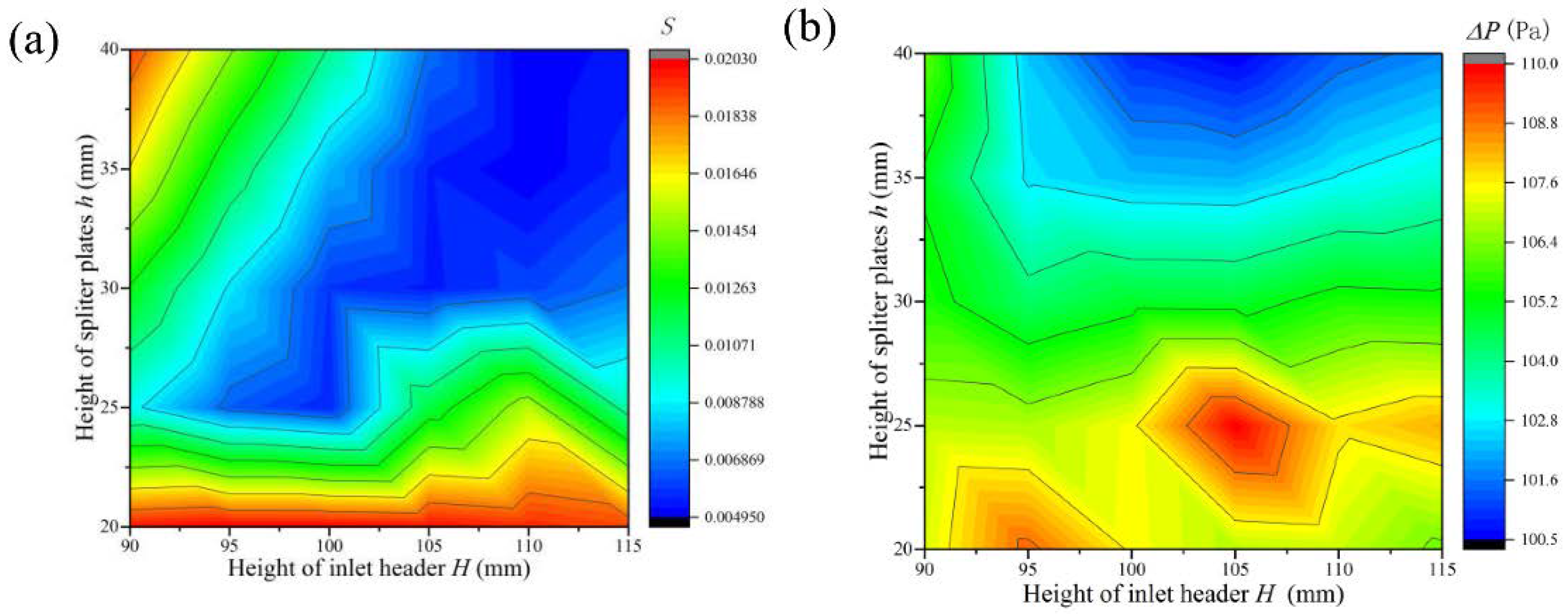
. The corresponding contour maps of flow maldistribution degrees and pressure drops are shown in Figure 13.
The difference between the maximum and minimum pressure drop was 7.54 Pa, which indicates that the two structural parameters had little influences on the pressure drop. However, the height of inlet header H and the height of splitter plates h had important influences on the flow maldistribution degree S. The maximum value of S was 0.020286 kg/s when H = 95 mm and h = 20 mm, and the minimum value of S was 0.004958 kg/s when H = 110 mm and h = 40 mm. The difference of S was 0.000020 kg/s between H = 110 mm, h = 40 mm and H = 110 mm and h = 35 mm, which was very little. However, the total weight of inlet header can be decreased through decreasing h. Therefore, considering the effectiveness of flow maldistribution, pressure drop and total weight of inlet header simultaneously, the optimum height of inlet header H and height of splitter plates h were determined as H = 110 mm and h = 35 mm, respectively.

3.5. Optimum Configuration of Improved Inlet Header

Based on the analysis results, the optimum configuration of improved inlet header is shown in Figure 14. The transition duct between inlet duct and header was a quasi-parabola transition duct, the number of splitter plates was n = 9, the inclined angle of the outermost plates was α = 51 , the height of inlet header was H = 110 mm, and the height of splitter plates was h = 35 mm. The angles of other splitter plates and the distances between adjacent plates are also listed in Figure 14. Using the optimum structure, the flow maldistribution degree was S = 0.004978 kg/s, and the pressure drop was Δ p = 102.8 Pa .

4. Performance Comparison among Three Inlet Header Configurations

The flow maldistribution degrees and pressure drop of three inlet header configurations (Configuration A in Figure 1, Configuration B in Figure 2, and Proposed Configuration C in Figure 14) were compared to verify the effectiveness of the proposed inlet header configurations.
The diameter of inlet duct D and the construction of outlet channels for the three inlet headers were the same. The velocity distributions in the three types of inlet headers are shown in Figure 15. The corresponding velocity distributions of outlet channels, flow maldistribution degrees, and pressure drops are shown in Figure 16. Compared with the traditional inlet header (Configuration A), the flow maldistribution degree S was decreased by 70.3% using inlet header for Configuration B, while the pressure drop was increased by 61.3% because the flow resistance was increased at the splayed perforated wing panels. Using the proposed improved inlet header (Configuration C), the flow maldistribution degree S was decreased by 91.5%, and the pressure drop was also decreased by 40.9%. The pressure drop may have been decreased due to (1) the angle between the inlet flow direction and splitter plates being small, which decreased the friction pressure drop; and (2) the diversion effect of splitter plates making the fluid flow in a specific direction, which reduced the inverse flow in the inlet header. Therefore, the improved inlet header can effectively enhance the flow uniformity and decrease the pressure drop.

5. Conclusions

An improved inlet header configuration with splitter plates for a plate-fin heat exchanger was proposed to decrease the flow maldistribution and pressure drop simultaneously. A computational fluid dynamic simulation was implemented to calculate the velocity distribution and pressure drop in inlet header, and the grid independence test determined the maximum sizes of grid cells to be 0.5 mm.
The influences of the transition duct between inlet duct and header, the number of splitter plates n , the inclined angle of the outermost plates α , the height of splitter plates h, and the height of inlet header H on the flow maldistribution degree S and pressure drop Δ p were analyzed, and the optimum configuration in the calculation condition was determined to be the quasi-parabola transition duct, with n = 9, α = 51 , H = 110 mm, and h = 35 mm.
In comparison with the traditional inlet header, the improved inlet header can decrease the flow maldistribution degree by 91.5% and the pressure drop by 40.9%, which is better than the inlet header with splayed perforated wing panels, which decreased the flow maldistribution degree S by 70.3% and increased the pressure drop by 61.3%. Therefore, the proposed improved inlet header can enhance the flow uniformly and heat transfer rates effectively, which can improve the total heat transfer rates of plate-fin heat exchanger.
Notably, the proposed inlet header configuration is independent from the operation conditions. Some further research can be implemented in the future:
(1) Regarding the other specific inlet mass flow rates or inlet Reynolds numbers, the specific structural parameters of the improved inlet header can be determined using the method in Section 3. In this way, the optimization design considering multiple operation conditions can be researched.
(2) Only the inlet header was analyzed in this work. The improvement effectiveness for thermal performance in the fin regions for the improved inlet header can be studied in the future.
(3) The influences of manufacturing, installation, and operation on the performance of proposed inlet headers can also be researched.

Author Contributions

Conceptualization, X.P.; Data curation, D.L. and Q.G.; Investigation, J.L.; Methodology, X.P., D.L. and J.L.; Supervision, S.J. All authors have read and agree to the published version of the manuscript.

Funding

This research was funded by the National Key Research and Development Program of China [under grant number 2017YFB0603704], the National Natural Science Foundation of China [under grant numbers 51875525 and U1610112], and the Zhejiang Provincial Natural Science Foundation of China [under grant number LY19E050004, LY20E050020], Open Foundation of the State Key Laboratory of Fluid Power and Mechatronic Systems [number: GZKF-201916].

Conflicts of Interest

The authors declare no conflict of interest.

Abbreviations

CFDcomputational fluid dynamic
Ddiameter of inlet flow pipe, mm
hheight of splitter plates, mm
Hheight of inlet header, mm
Llength of inlet header, mm
MPFHEmulti-stream plate-fin heat exchangers
nnumber of splitter plates
Δ p pressure drop, Pa
p i n input pressure, Pa
p o u t outlet pressure, Pa
m ˙ i mass flow rates of i-th outlet channel, kg/s
m ¯ mean of mass flow rates of all channels, kg/s
Rradius of inlet header, mm
Sflow maldistribution degree
Greek Symbols:
α inclined angle of the outermost plates, °
Subscripts:
ii-th outlet channel

References

  1. Das, P.K.; Ghosh, I. Thermal design of multistream plate fin heat exchangers—A state-of-the-art review. Heat Transf. Eng. 2012, 33, 284–300. [Google Scholar] [CrossRef]
  2. Xue, Y.; Ge, Z.; Du, X.; Yang, L. On the Heat Transfer Enhancement of Plate Fin Heat Exchanger. Energies 2018, 11, 1398. [Google Scholar] [CrossRef] [Green Version]
  3. Tharkar, A.D.; Mahulikar, S.P. The mean temperature difference method for micro heat exchanger analysis considering property variation. Heat Transf. Eng. 2019, 40, 605–615. [Google Scholar] [CrossRef]
  4. Yusof, T.M.; Ibrahim, H.; Azmi, W.H.; Rejab, M.R.M. Thermal analysis of earth-to-air heat exchanger using laboratory simulator. Appl. Therm. Eng. 2018, 134, 130–140. [Google Scholar] [CrossRef]
  5. Javid, S.M.; Farshidianfar, A.; Golparvar, S.B. An alternative algorithm for optimal design of plate heat exchangers. Adv. Mech. Eng. 2015, 7, 865129. [Google Scholar] [CrossRef] [Green Version]
  6. Song, J.-Y.; Hah, S.; Kim, D.; Kim, S.-M. Enhanced flow uniformity in parallel mini-channels with pin-finned inlet header. Appl. Therm. Eng. 2019, 152, 718–733. [Google Scholar] [CrossRef]
  7. Pasquier, U.; Chu, W.X.; Zeng, M.; Chen, Y.T.; Wang, Q.W.; Ma, T. CFD simulation and optimization of fluid flow distribution inside printed circuit heat exchanger headers. Numer. Heat Transf. Part A Appl. 2016, 1–17. [Google Scholar] [CrossRef]
  8. Brenk, A.; Pluszka, P.; Malecha, Z. Numerical Study of Flow Maldistribution in Multi-Plate Heat Exchangers Based on Robust 2D Model. Energies 2018, 11, 3121. [Google Scholar] [CrossRef] [Green Version]
  9. Lalot, S.; Lang, P.F.S.K.; Bergles, A.E. Flow maldistribution in heat exchangers. Appl. Therm. Eng. 1999, 19, 847–863. [Google Scholar] [CrossRef]
  10. Rao, B.P.; Das, S.K. An experimental study on the influence of flow maldistribution on the pressure drop across a plate heat exchanger. J. Fluids Eng. 2004, 126, 680–691. [Google Scholar] [CrossRef]
  11. Chin, W.M. The effect of combined flow and temperature maldistribution on heat exchangers- characteristics of deterioration factor ratio Y. J. Heat Transf. 2013, 135, 121802. [Google Scholar] [CrossRef]
  12. Salehi, S.; Afshin, H.; Farhanieh, B. Numerical investigation of the inlet baffle, header geometry, and triangular fins effects on plate-fin heat exchangers performance. Heat Transf. Eng. 2015, 36, 1397–1408. [Google Scholar] [CrossRef]
  13. Niroomand, R.; Saidi, M.H.; Hannani, S.K. A quasi-three-dimensional thermal model for multi-stream plate fin heat exchangers. Appl. Therm. Eng. 2019, 157, 113730. [Google Scholar] [CrossRef]
  14. Jung, J.; Hwang, G.; Baek, S.; Jeong, S.; Rowe, A.M. Partial flow compensation by transverse bypass configuration in multi-channel cryogenic compact heat exchanger. Cryogenics 2013, 52, 19–26. [Google Scholar] [CrossRef]
  15. Peng, X.; Qiu, C.; Li, J.; Jiang, S. Thermal compensation effect of passage arrangement design for inlet flow maldistribution in multiple-stream plate-fin heat exchanger. Heat Transf. Eng. 2019, 1–10. [Google Scholar] [CrossRef]
  16. Jiao, A.; Zhang, R.; Jeong, S. Experimental investigation of header configuration on flow maldistribution in plate-fin heat exchanger. Appl. Therm. Eng. 2003, 23, 1235–1246. [Google Scholar] [CrossRef]
  17. Wen, J.; Li, Y.; Zhou, A.; Zhang, K. An experimental and numerical investigation of flow patterns in the entrance of plate-fin heat exchanger. Int. J. Heat Mass Transf. 2006, 49, 1667–1678. [Google Scholar] [CrossRef]
  18. Ismail, L.S.; Ramesh, C.R.; Shah, K. Numerical study of flow patterns of compact plate-fin heat exchangers and generation of design data for offset and wavy fins. Int. J. Heat Mass Transf. 2009, 52, 3972–3983. [Google Scholar] [CrossRef]
  19. Yaïci, W.; Ghorab, M.; Entchev, E. 3D CFD study of the effect of inlet air flow maldistribution on plate-fin-tube heat exchanger design and thermal–hydraulic performance. Int. J. Heat Mass Transf. 2016, 101, 527–541. [Google Scholar] [CrossRef]
  20. Yang, H.; Wen, J.; Gu, X.; Li, K.; Wang, S.; Li, Y. Improvements on flow distribution and heat transfer performance of plate-fin heat exchangers by qusai-S type header configuration. Heat Transf. Eng. 2017, 38, 1547–1560. [Google Scholar] [CrossRef]
  21. Tu, X.-C.; Wu, Y.; Kim, H.-B. Improvement of two-phase flow distribution in the header of a plate-fin heat exchanger. Int. J. Heat Mass Transf. 2018, 123, 523–533. [Google Scholar] [CrossRef]
  22. Yang, H.; Wen, J.; Tong, X.; Li, K.; Wang, S.; Li, Y. Numerical investigation on configuration improvement of a plate-fin heat exchanger with perforated wing-panel header. J. Enhanc. Heat Transf. 2016, 23, 1–21. [Google Scholar] [CrossRef]
  23. Shojaeefard, M.H.; Nourbakhsh, S.D.; Zare, J. An investigation of the effects of geometry design on refrigerant flow mal-distribution in parallel flow condenser using a hybrid method of finite element approach and CFD simulation. Appl. Therm. Eng. 2017, 112, 431–449. [Google Scholar] [CrossRef]
  24. Raul, A.; Bhasme, B.N.; Maurya, R.S. A numerical investigation of fluid flow maldistribution in inlet header configuration of plate fin heat exchanger. Energy Procedia 2016, 90, 267–275. [Google Scholar] [CrossRef]
Figure 1. Conventional inlet header (Configuration A).
Energies 13 01323 g001
Figure 2. Inlet header with splayed perforated wing panels (Configuration B).
Energies 13 01323 g002
Figure 3. Improved inlet header (Configuration C): (a) Construction; (b) design parameters.
Energies 13 01323 g003
Figure 4. Results of the grid independence test.
Energies 13 01323 g004
Figure 5. Results comparison of the CFD simulation and PIV experimental test.
Energies 13 01323 g005
Figure 6. Three typical transition ducts: (a) Direct transition duct; (b) triangle transition duct; (c) quasi-parabola transition duct.
Energies 13 01323 g006
Figure 7. Velocity contours in the inlet header: (a) Direct transition duct; (b) triangle transition duct; (c) quasi-parabola transition duct.
Energies 13 01323 g007
Figure 8. Comparison of mass flow rates at outlet channels and flow maldistribution degree.
Energies 13 01323 g008
Figure 9. Velocity distribution in the header with different number of splitter plates: (a) n = 8; (b) n = 9.
Energies 13 01323 g009
Figure 10. Mass flow rates at the outlet channles under different odd numbers of splitter plates.
Energies 13 01323 g010
Figure 11. Flow maldistribution degree and pressure drop under different odd numbers of splitter plates.
Energies 13 01323 g011
Figure 12. Flow maldistribution degree and pressure drop under different inclined angle of the outermost splitter plates.
Energies 13 01323 g012
Figure 13. Contour map under different combinations of H and h: (a) Flow maldistribution degree; (b) pressure drop.
Energies 13 01323 g013
Figure 14. Optimum configuration of improved inlet header.
Energies 13 01323 g014
Figure 15. Velocity distribution in the inlet header under different configurations: (a) Direct transition duct; (b) triangle transition duct; (c) quasi-parabola transition duct.
Energies 13 01323 g015
Figure 16. Comparison results: (a) Mass flow rates; (b) flow maldistribution degree and pressure drop.
Energies 13 01323 g016
Table 1. Flow maldistribution degree S (10−2 kg/s) under different combinations of inlet header height H and splitter plate height h.
H = 90 mmH = 95 mmH = 100 mmH = 105 mmH = 110 mmH = 115 mm
h = 20 mm1.99492.02862.02482.00641.9611.9111
h = 25 mm0.90890.65040.56141.18261.53341.6072
h = 30 mm1.25430.86260.58740.54920.60840.6923
h = 35 mm1.64211.16160.78570.55640.49780.5735
h = 40 mm1.91631.47041.05940.67730.49580.5439
Table 2. Pressure drop ∆p (Pa) under different combinations of inlet header height H and splitter plate height h.
H = 90 mmH = 95 mmH = 100 mmH = 105 mmH = 110 mmH = 115 mm
h = 20 mm107.15108.95107.49106.86107106.24
h = 25 mm106.9106.81107.45109.92107.73108.22
h = 30 mm105.54104.36104.91104.87105.52105.43
h = 35 mm105.07102.7102.3102.22102.86103.29
h = 40 mm106.14102.41100.87100.45101.41101.84

