Article

Effect of Secondary Vortex Flow Near Contact Point on Thermal Performance in the Plate Heat Exchanger with Different Corrugation Profiles

School of Mechanical Engineering, Chung-Ang University, 84 Heukseok-ro, Dongjak-gu, Seoul 06974, Korea
*
Author to whom correspondence should be addressed.
Energies 2020, 13(6), 1328; https://doi.org/10.3390/en13061328
Submission received: 13 January 2020 / Revised: 5 March 2020 / Accepted: 9 March 2020 / Published: 12 March 2020
(This article belongs to the Special Issue Fluid Flow and Heat Transfer Ⅱ)

Abstract

:
The present study numerically investigates thermal performance and turbulent flow characteristics of chevron-type plate heat exchangers with sinusoidal, trapezoidal, triangular, and elliptical corrugation profiles. The commercial code of ANSYS Fluent (v. 17.0) is used for computational fluid dynamics (CFD) simulation with the realizable k-ε model. In particular, we focus on the influence of configuration shape on a substantial change in flow direction near the contact point, yielding local vorticity. As a result, secondary vortical motions are observed in the flow passage with vorticity that is distributed locally and which changes near the contact point. Higher flow mixing generated and distributed by the secondary vortical motions contributes to the increase of the Colburn j-factor as well as the friction factor. The highest Colburn j-factor and friction factor are obtained for an elliptical profile, compared to other shapes, because of the increase in the vortex strength near the contact point.

1. Introduction

A chevron-type plate heat exchanger occupies little space and achieves better heat transfer performance than other heat exchangers because of its relatively large heat transfer area and its small corrugated gaps, which yield complex flows [1]. Plate heat exchangers have been widely applied to various industrial fields such as the chemical industries, ocean thermal energy conversion systems, and waste heat recovery units because of their compact and easy to clean features [2,3]. The chevron shape, heat transfer area, corrugation profile, and operating conditions mainly affect the heat transfer and pressure drop characteristics of a plate heat exchanger. However, fluid temperature and pumping power limits exist in the practical application of heat exchangers. Thus, some geometric parameters should be considered to enhance the heat transfer performance of the plate heat exchangers [4].
In recent decades, considerable effort has been invested in examining the effects of geometric parameters (chevron angle, the ratio of chevron pitch to height, and corrugation profiles) on flow patterns and heat transfer characteristics [5,6]. It is important to improve heat transfer performance and decrease the pressure drop of the plate heat exchanger. Focke and Knibbe [7] performed flow visualization with sinusoidal corrugated channels. They analyzed flow characteristics concerning the chevron angle. In the low angle case, the flow tends to follow the corrugations and only changes direction at the sidewalls, whereas complicated flow patterns such as zig-zag flow occur in the high angle case since flow reflection takes place at the contact points. Furthermore, experimental and numerical studies with trapezoidal corrugation profiles were carried out to analyze fluid flow distributions and thermal fields within the channel [8,9]. Irregular flow distribution and non-uniform thermal fields were observed due to the corrugation profile causing flow resistance in the streamwise direction. Tsai et al. [10] examined the pressure drop and flow distribution in the plate heat exchanger. They reported that contact points inside the flow channel divided the mean flow into two streams and caused considerable mixing that enhanced the heat transfer.
Many studies have also been conducted to improve the heat transfer performance of the plate heat exchanger by adjusting the chevron angle, β, and pitch to height ratio, P/H [11,12]. Muley and Manglik [13] reported the thermal and pressure drop characteristics of a single-phase flow with respect to the chevron angle using the Colburn j-factor and Fanning-friction factor. They constructed a mixed chevron plate with a sinusoidal profile by using both plates with chevron angles of 30° and 60°. In the mixed plate case, fully-developed turbulent flow was observed for Reynolds numbers of 1000 or higher. The heat transfer rate and pressure drop increased with the chevron angle because of the disruption of the boundary layer and the swirl flow generation. Lee and Lee [14,15] investigated the unsteady flow characteristics of a plate heat exchanger by changing the chevron angle and the ratio of the chevron pitch to height. For this study, they adopted a unitary cell, which is a repeated section of a flow channel. In this simulation, the steady flow without swirling motion was observed in the laminar regime, whereas oscillating and swirling motion in the furrow direction appeared in the turbulent regime. Also, the heat transfer coefficient increased as P/H decreased.
Moreover, the corrugation profile of a plate heat exchanger becomes important in the design of the heat exchanger [16]. Numerical simulations were conducted to compare the heat transfer rate and pressure drop with triangular and trapezoidal profiles [17]. The trapezoidal profile showed higher heat transfer performance compared to the triangular profile. Zhang and Che [18] performed numerical simulations to evaluate the influence of the corrugated plates. They reported of vortices being generated in the flow channels and compared the heat transfer performance with different corrugated plates.
Many researchers conducted experiments and numerical analyses of the flow and heat transfer characteristics in plate heat exchangers. It is necessary to understand the complex flow motion caused by the chevron shape and corrugation profile. However, it is difficult to directly analyze the internal flows in all channels of a plate heat exchanger because of the considerable computational cost. Most of the numerical studies took only one flow channel and excluded contact points when using a unitary cell. Also, there is a lack of information on the effect of corrugation profiles on the flow and heat transfer characteristics. Thus, the present study aims to examine the influence of corrugation configurations such as sinusoidal, trapezoidal, triangular, and elliptical shapes on heat transfer and pressure drop characteristics of the plate heat exchanger.

2. Numerical Simulation

2.1. Mathematical Representations

The present study investigates the turbulent flow and heat transfer characteristics in the plate heat exchanger using the following assumptions: there is no phase change inside the channels, the fouling effect is ignored, and all surfaces are assumed to be smooth. The transport equations of mass, momentum, energy, and the realizable k-ε model are solved assuming steady state conditions to analyze the complicated flow. The corrugation profile might cause complicated turbulent flows in the channel even at a relatively low Reynolds number [4]. The Reynolds number (Re = ρumDe/μ) is a function of the density of water, mean velocity, the viscosity of water, and equivalent diameter defined as twice the height of the corrugation profile (De = 2H) [19,20]. The fluid flow is considered in the laminar region at Re < 400 and transition region at 400 < Re < 1000. The internal flow of the plate heat exchanger can be regarded as the fully developed turbulent flow when Re > 1000 [13]. In particular, the realizable k-ε model is known as an appropriate model for the flows involving streamline curvature and vortices. The non-equilibrium wall function is also used for the anisotropic turbulent flows including separation, reattachment, and impingement to accurately describe wall shear stress and heat transfer [21]. The Reynolds-Averaged Navier-Stokes (RANS) equations for the mathematical description of the viscous flow are as follows:
  ( ρ u i ) x i = 0  
  x j ( ρ u i u j ) = p x i + x j [ μ ( u i x j + u j x i 2 3 δ i j u l x l ) ]  
  x j [ u i ( ρ E + p ) ] = x j [ ( k f + C p μ t Pr t ) T x j ]
μ t = ρ C μ k 2 ε  
where ρ is the density of water, ui is the velocity vector, E is the total energy, kf is the thermal conductivity of water, Cp is the specific heat of water, μt is the turbulent viscosity, Prt is the turbulent Prandtl number, k is the turbulent kinetic energy, and ε is the dissipation rate. The transport equations for k and ε are as follows:
  x j ( ρ k u j ) = x j [ ( μ + μ t σ k ) k x j ] μ t S 2 ρ ε  
  x j ( ρ ε u j ) = x j [ ( μ + μ t σ ε ) ε x j ] + ρ C 1 S ε ρ C 2 ε 2 k + ν ε  
where S = (2SijSij)0.5 is the modulus of the mean rate of the strain tensor, and ν is the kinematic viscosity of water. The σk and σε are the turbulent Prandtl numbers for k and ε, respectively [21].

2.2. Computational Domain and Boundary Conditions

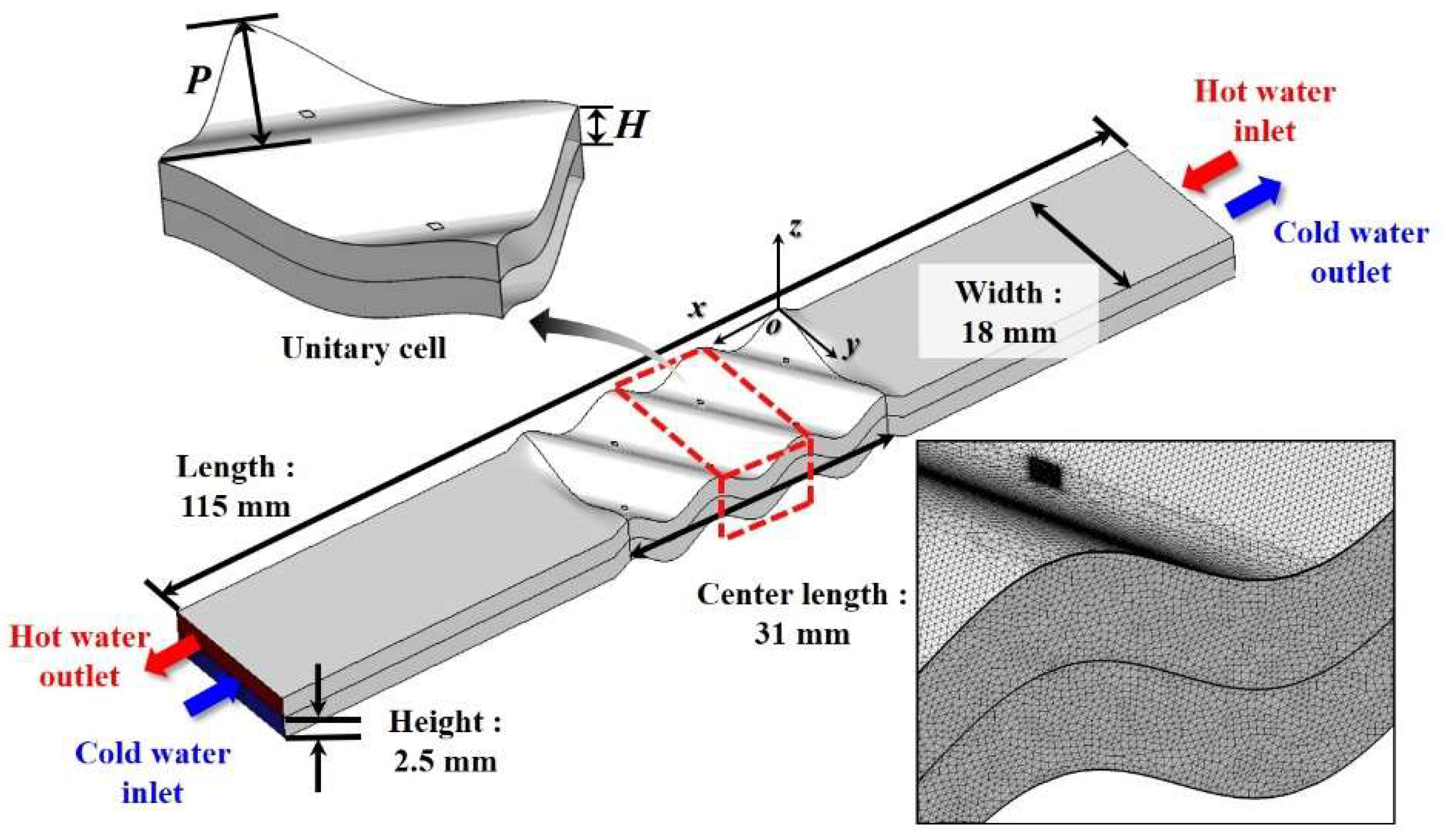
Figure 1a illustrates the partial plate of the chevron-type plate heat exchanger. The metal plates with the chevron shape and corrugation profiles are stacked to form the internal flow channel, indicating that there are many contact points inside the plate heat exchanger depending on the key geometrical variables such as chevron angle, height, and pitch [22]. In fact, high mesh resolution is important to obtain accurate numerical solutions. Considering the entire geometry of the plate heat exchanger, there would be some limitations in creating computational grids according to different corrugation profiles owing to high aspect ratio and prohibitive mesh size locally to get high mesh resolution. Instead, the unitary cell, which is repeated periodically in the plate heat exchanger, has been often used for efficient analysis of heat transfer and pressure drop with reasonable accuracy [14,15]. Therefore, the present study used the three unitary cells considering contact points in the flow channel, as illustrated in Figure 1b.
The computational domain constructed with three unitary cells is extended in the mainstream direction for reducing possible numerical errors that might occur owing to uncertain boundary conditions, as shown in Figure 2. The base configuration is taken from the configuration of Gherasim et al. [8,9] with the channel height of 2.5 mm, chevron pitch of 9 mm, and chevron angle of 60°. The total length of the computational domain is 115 mm. There are unitary cells with a length of 10.33 mm, which contain two contact points causing the change in flow motion. The heat exchange occurs in the middle plate of the unitary cells that are located between the hot water and cold water channels. The denser meshes were created near the contact point to accurately capture a rapid change in turbulent flow. The total number of elements for all cases is about 10,800,000, which has been determined by the grid independence tests. Four different corrugation profiles such as sinusoidal, trapezoidal, triangular, and elliptical shapes were considered for simulations, as presented in Figure 3.
The boundary conditions are set with the experimental conditions used by Gherasim et al. [8]. The mass flow rate of hot water is set to 3.803 × 10⁻³, 4.753 × 10⁻³, 5.704 × 10⁻³, and 6.655 × 10⁻³ kg/s, correspondingly in the range of 800 ≤ Re = ρumDe/μ ≤ 1400. The mass flow rate of cold water is maintained at 7.352 × 10⁻³ kg/s. The initial temperatures of the hot and cold water channels are taken as 323 and 298 K, respectively. The periodic condition is used for the side walls located in the unitary cell to mimic the repeated geometry of the plate heat exchanger. The adiabatic condition is also applied to the top and bottom plates of the unitary cells. In particular, the conjugate heat transfer is considered with the coupled wall conditions at the interfaces. The properties of water are considered to be temperature dependent, and each property is set to piecewise-linear functions of temperature. The plates of the heat transfer surface are made of stainless steel, and its thermal properties are listed in Table 1.

2.3. Performance of Plate Heat Exchanger

Practically, the plate heat exchanger is designed with some of the key parameters such as Colburn j-factor and Darcy friction factor in characterizing heat transfer and pressure drop [24]. These two factors are defined as
  j = N u Pr 1 / 3 Re
f = 2 Δ p D e ρ L u m 2
N u = h D e k f
where ∆p is the pressure drop of the unitary cell, L is the characteristic length of the unitary cell (L = 0.0103 m), um is the mean velocity of the water, and h is the heat transfer coefficient that is calculated by
h = Q t o t A Δ T L M T D
Q t o t = m ˙ c p ( T i n T o u t )
Δ T L M T D = ( T c ,   o u t T h ,   i n ) ( T c ,   i n T h ,   o u t ) ln [ ( T c ,   o u t T h ,   i n ) ( T c ,   i n T h ,   o u t ) ]
where Qtot is the total heat transfer rate, A is the surface area of the chevron plate, ∆TLMTD is the log mean temperature difference, and is the mass flow rate.

3. Results and Discussion

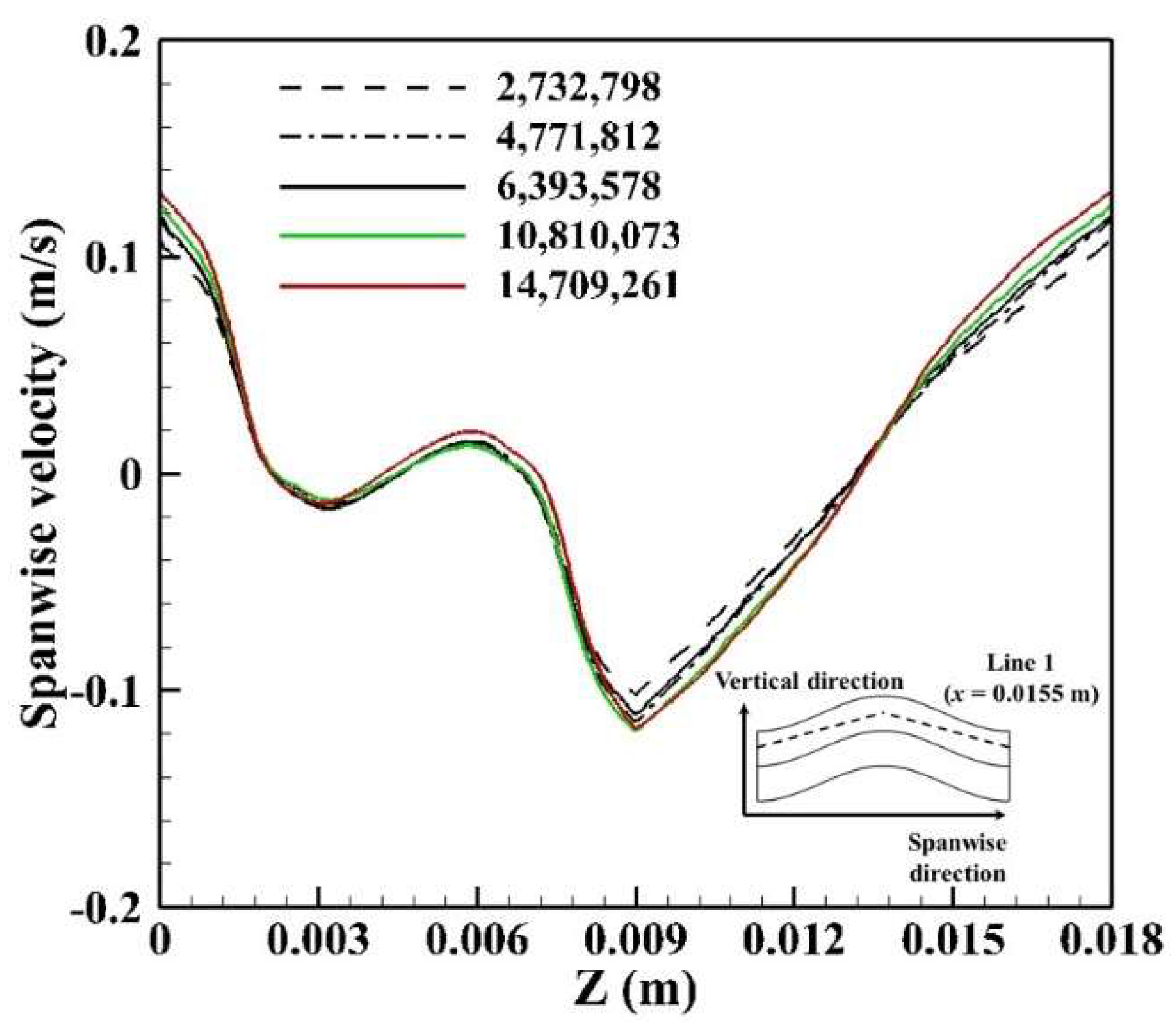
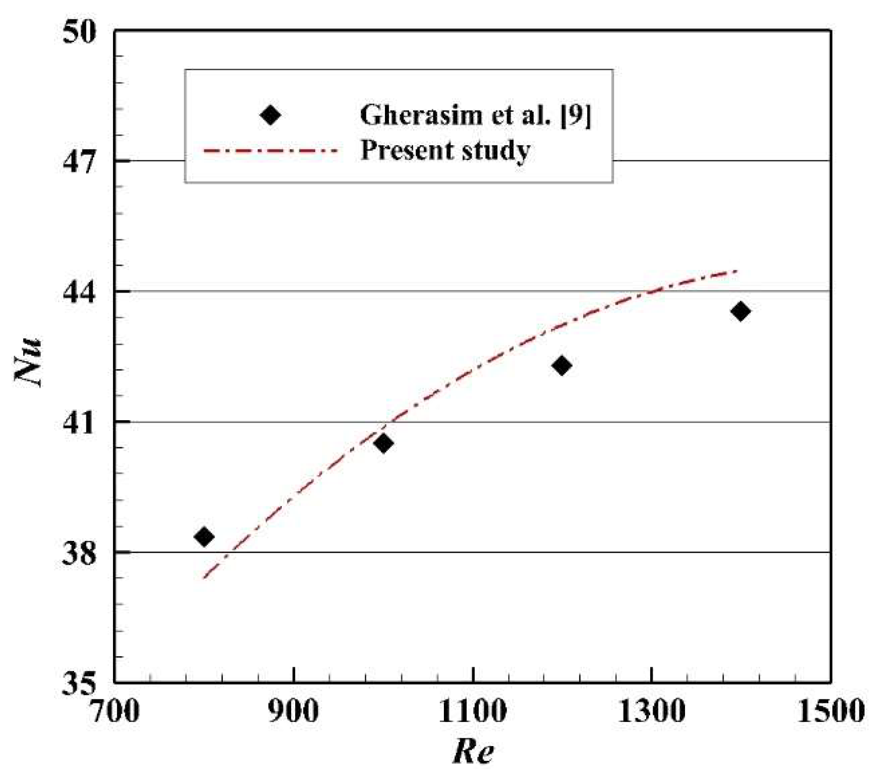
The grid independence test is an essential process to obtain grid-converged solutions. We conducted the preliminary tests for five different grid systems. Figure 4 compares the distributions of spanwise velocity components acquired along Line 1 of the hot water channel. Considering the maximum deviation of 4.64% (at Z = 0.018 m) between the fourth and fifth grid system, it has been determined to apply the grid resolution of the fifth grid system to the meshes used in all further simulations. For validation, we compared our predictions with the numerical results provided by Gherasim et al. [9], as shown in Figure 5, showing relatively acceptable results with a maximum deviation of 2.2%.
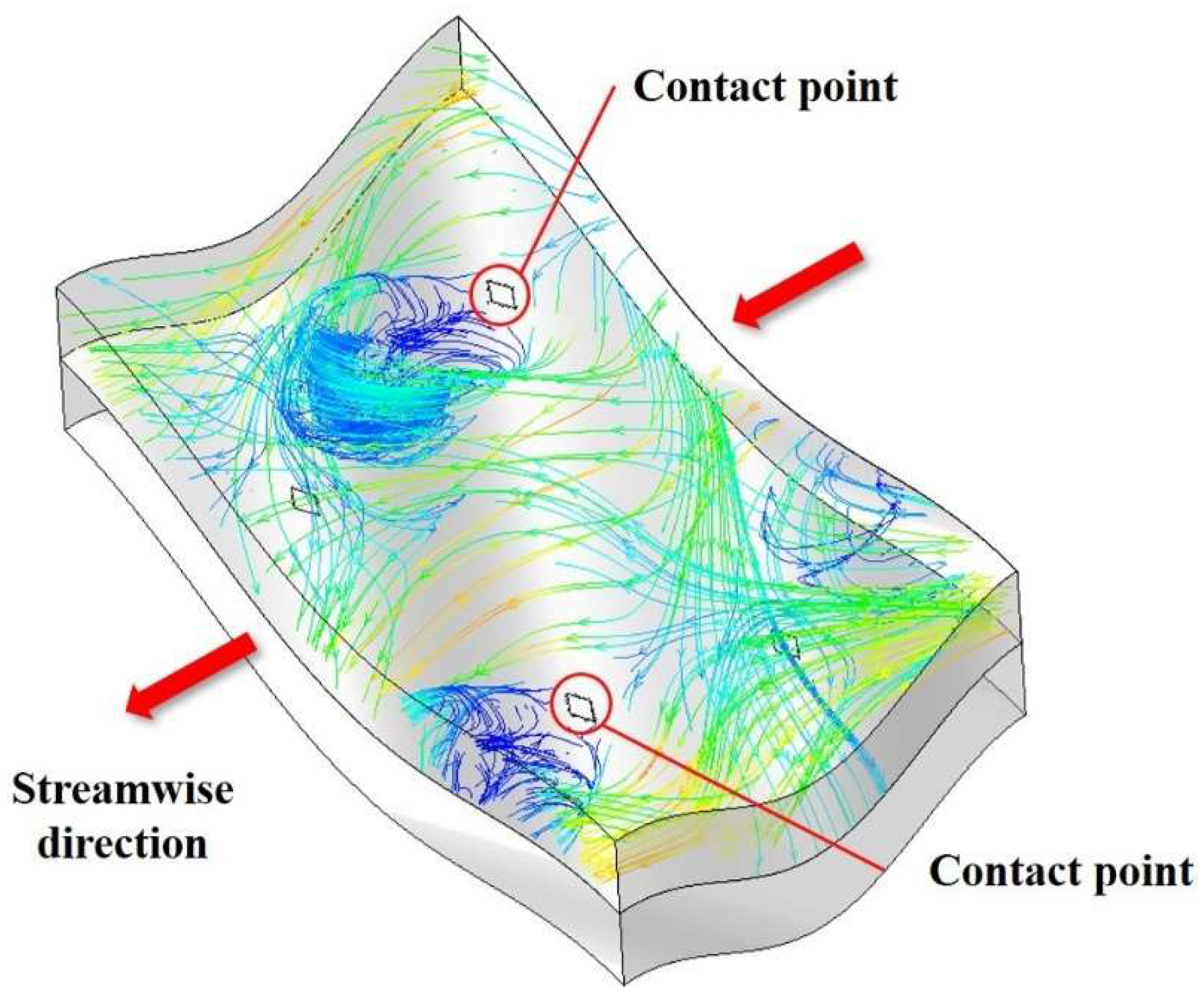
Figure 6 shows very complicated flow motions in the hot water channel in the case of the sinusoidal corrugation profile. A similar flow pattern is observed for the cold water channel. The secondary and complex flow occurs in the unitary cell owing to the contact points, which have a similar effect like a bluff body. The secondary flow contributes to the enhancement of flow mixing. In particular, it leads to an interaction between the mean flow and the near-wall flows, improving the heat transfer performance while also leading to an increase in pressure drop [25].
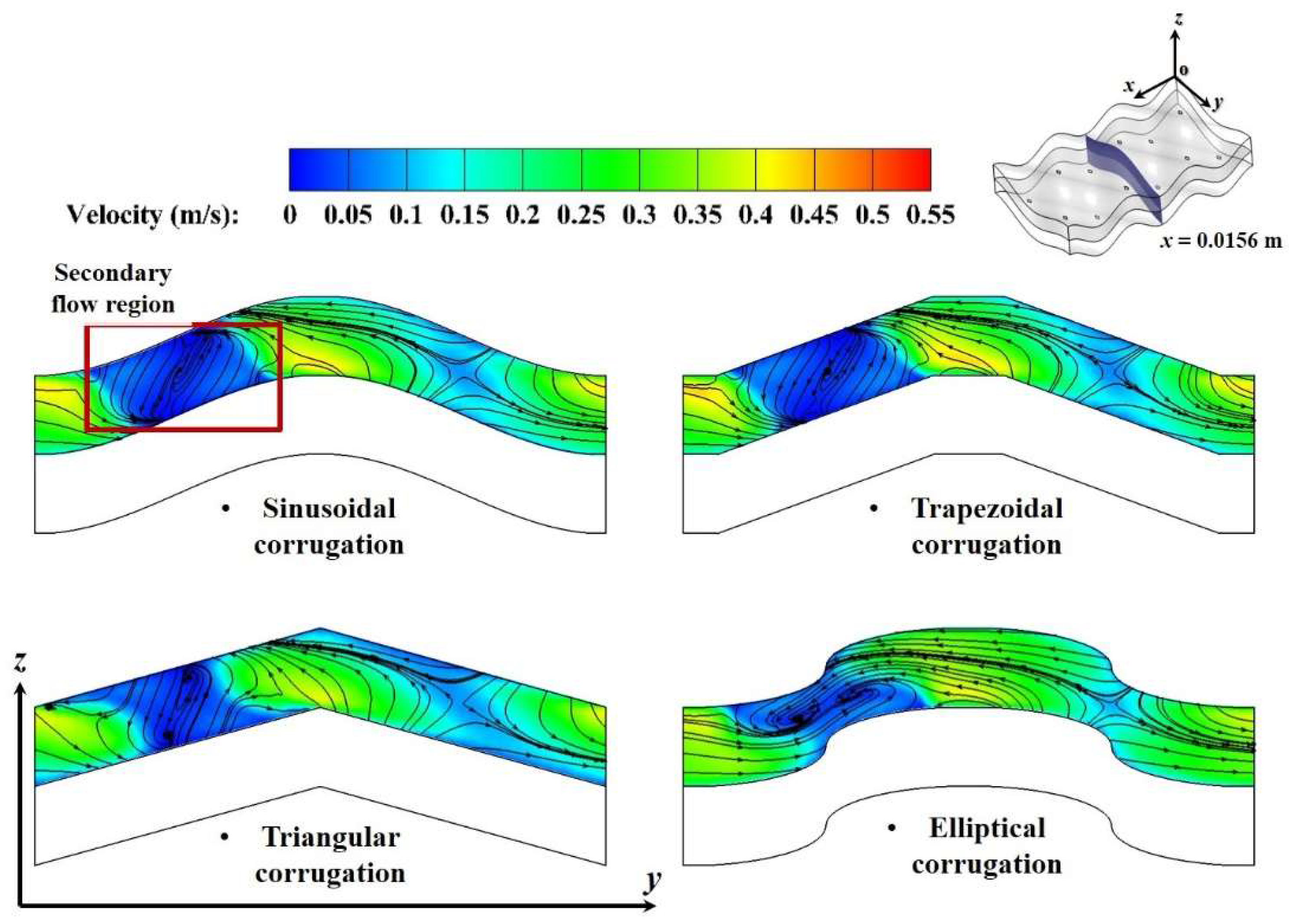
Figure 7 depicts the velocity distribution and streamlines of hot water at x = 0.0156 m according to the variation of corrugation profiles at the Reynolds number of 1400. In the secondary flow region, the flow velocity is low, while the flow is actively mixed. The interaction between the narrow channel near the contact points and the accelerated flow over the crest causes a stronger secondary flow, resulting in higher flow mixing that affects the heat transfer and pressure drop [26]. In particular, the elliptical corrugation profile shows more rotational flow motions than the others. The spatial distribution of the vorticity magnitude provides a quantitative measure of local flow mixing since it measures the local rotation of a fluid element. It is defined as the curl of the flow velocity.
= × V = ( u k y u j z ) i ^ + ( u i z u k x ) j ^ + ( u j x u i y ) k ^
Figure 8 shows the vorticity magnitude distributions for different corrugation profiles. The sinusoidal and trapezoidal profiles show similar distributions of vorticity magnitude. In particular, the elliptical profile exhibits a higher vorticity magnitude distribution in the secondary flow region compared to sinusoidal, trapezoidal, and triangular shape. These vorticity magnitude distributions can be analyzed with an understanding of flow channel variation along the streamwise direction (x-direction).
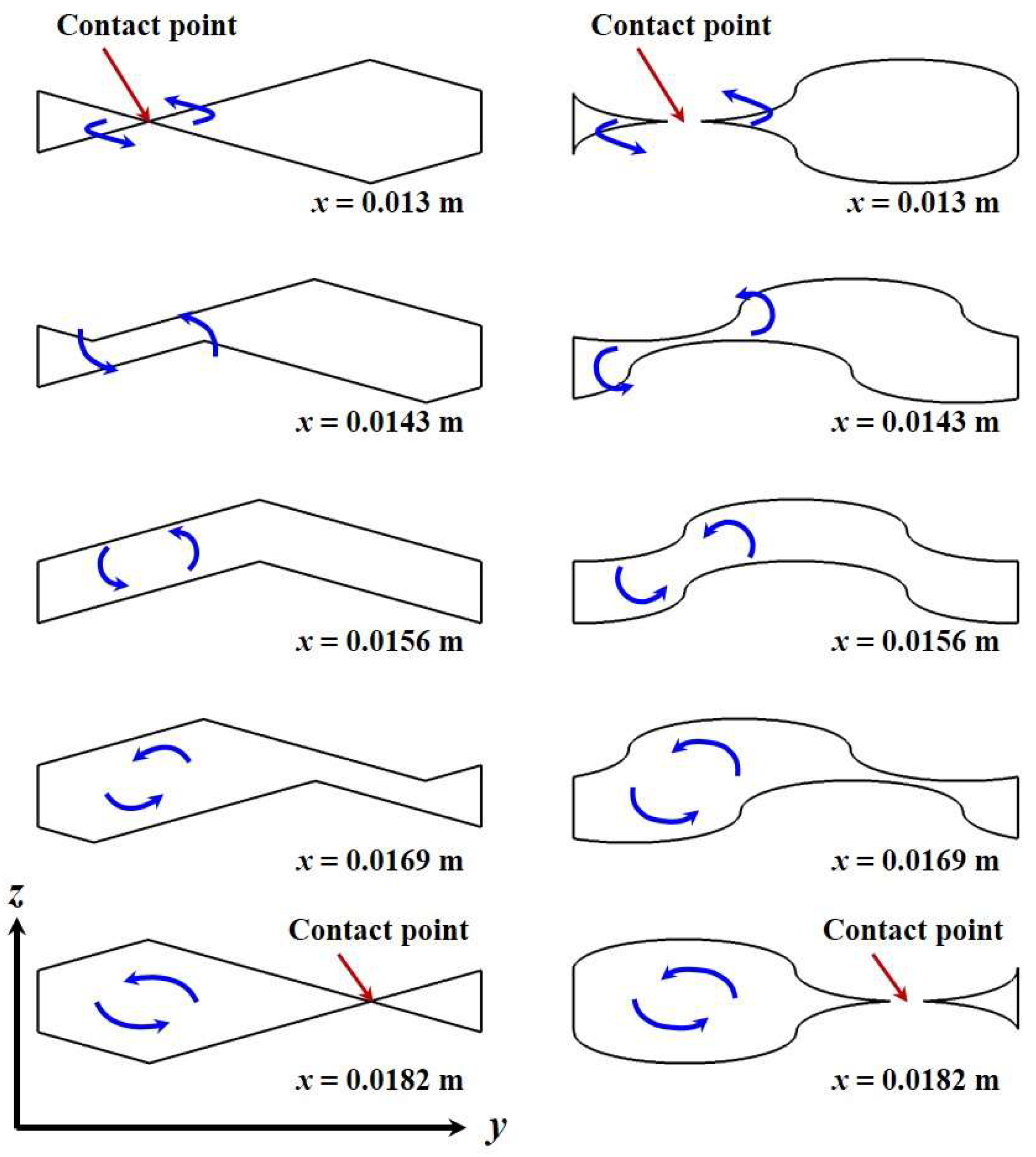
Figure 9 shows the variation of cross-sectional shapes for triangular and elliptical profiles along the streamwise direction. The mainstream is separated into two streams by the contact point. These two streams flow along the corrugation shapes and show such vortical motions that appear at every contact point in the plate heat exchanger. The elliptical profile has a relatively narrow channel near the contact point in the spanwise direction (y-direction) compared to the triangular profile. Also, the channel height increases drastically along the streamwise direction, creating much stronger streamwise vorticity.
The normalized vorticity is introduced for characterizing the rotational flows, as expressed by
ζ i = | i | max
where |Ωi| is the vorticity magnitude for each direction, and Ωmax is the maximum vorticity magnitude of each corrugation profile along Line 1, which is located at the center of the hot water channel. Figure 10 presents the normalized vorticity distribution of the hot water channel. The normalized vorticity is larger in the left side of the graph for all corrugation profiles, because the range of y = 0−0.009 m is located right behind a contact point, while the range of y = 0.009−0.018 m is located past the recirculation area of the previous contact point, as shown in Figure 10b. A larger proportion of vertical direction (z-direction) vorticity is observed for all cases because the contact points separate the mean flow into two streams. This leads to shear layers with high vertical direction vorticity. However, the elliptical profile shows a relatively higher ratio of streamwise vorticity, which plays an important role in the heat transfer performance, inducing the mixing between mainstream and near-wall flow.
In Figure 11a, higher streamwise vorticity appears in the secondary flow region for all corrugation profiles. The fluid flow is separated into two different streams owing to the contact point, causing flow acceleration and secondary flows through the narrow gap between the corrugation plates. The sinusoidal and trapezoidal profiles present similar distributions of streamwise vorticity, and the triangular profile shows the lowest distribution. On the contrary, the elliptical corrugation profile exhibits the largest area of high streamwise vorticity, comprising a considerable part of the channel cross section. For quantitative analysis, the streamwise vorticity distribution along Line 1 is presented in Figure 11b. For all cases, lower streamwise vorticity appears at y = 0.0045 m due to momentum losses and a higher value of streamwise vorticity occurs in the secondary flow region (y = 0.0015 m and y = 0.0075 m). In particular, the elliptical profile indicates the highest streamwise vorticity owing to the narrow channel in a spanwise direction near the contact point and a drastic increase of flow channel in the streamwise direction.
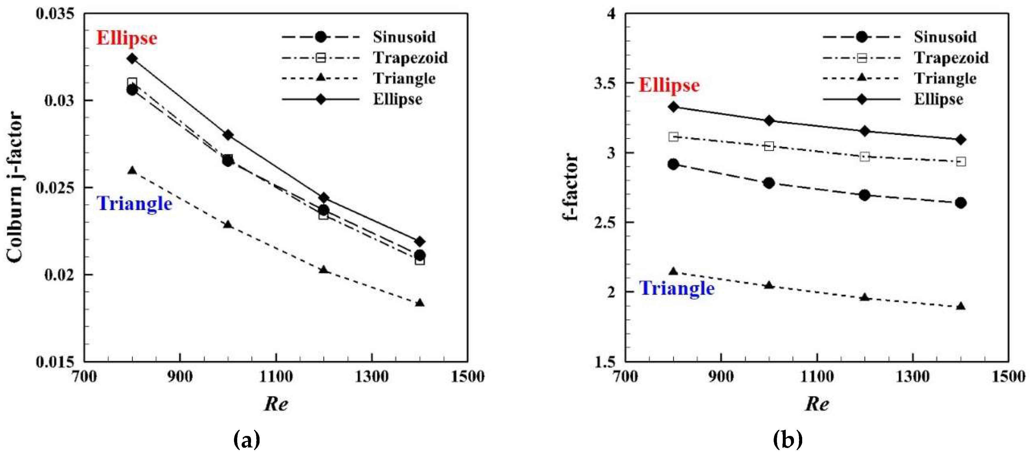
The thermal performance and pressure drop are examined using the unitary cell that is in the central location ignoring the influence of the extended region of the computational domain. An increase of the Colburn j-factor signifies an enhancement of heat transfer performance. Generally, the Colburn j-factor decreases with an increase in the Reynolds number, as shown in Figure 12a. Also, it shows the highest heat transfer performance in the elliptical profile, similar to the tendency of streamwise vorticity. The narrow flow channel near the contact point generates a stronger secondary flow, which increases the mixing rate of the flow in the vicinity of the heat transfer surface. Figure 12b provides the friction factor distribution for different corrugation profiles to analyze the pressure drop. It shows that the highest pressure drop occurs for the elliptical profile, which coincides with the results obtained for the heat transfer characteristics. The enhancement of flow mixing causes the increase in the heat transfer performance and the pressure drop.
It is important to analyze the relationship between the heat transfer performance and pressure drop in the plate heat exchanger. The volume goodness factor is used to analyze the correlation between the heat transfer coefficient and the pumping power per unit surface area. It is expressed as [22]
h = k N u D e = μ C p D e Pr 2 / 3 ( j Re )
P p A = m ˙ Δ p ρ A = μ 3 2 ρ D e 3 ( f Re 3 )
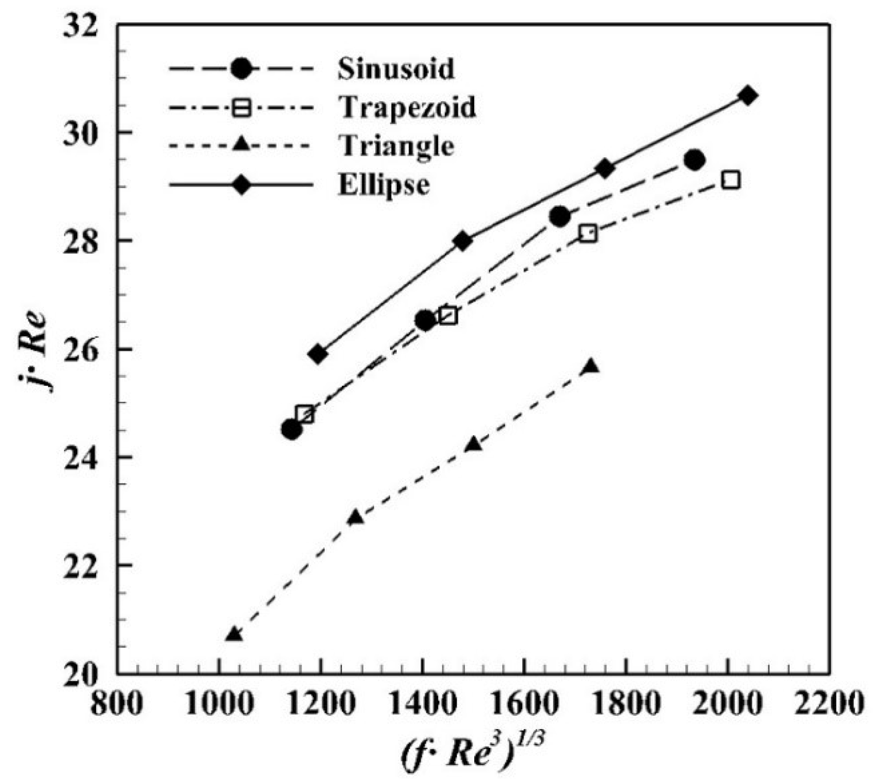
This is an important parameter for designing the surface structure of the plate heat exchanger. Figure 13 compares the heat transfer coefficient considering pumping power with different corrugation profiles. The heat transfer performance increases with the pumping power for all cases. In particular, the heat transfer coefficient of the elliptical profile represents the highest value at a given pumping power. This means that the entire volume of the plate heat exchanger can be reduced by using the elliptical corrugation profile with higher heat transfer performance.

4. Conclusions

Numerical simulations were conducted extensively for analyzing turbulent flows and heat transfer characteristics of the chevron plate heat exchangers with different corrugation profiles. The current simulation did not consider the fully developed flow in the unitary cells because of the computational cost. In the future, further extension of the unitary cell will be made for more accurate analysis. The conclusions are drawn as follows:
From the results, it is shown that strong secondary flow in the flow passage is generated near the contact points. These vertical motions play an important role in mixing flows and consequently enhancing the thermal performance of the plat heat exchangers. The substantial changes in flow motions are observed depending on different chevron corrugation geometries. It is found that the channel height increases after the contact point and is affected by concave and convex shapes. The elliptical shape enables to provide larger space variation of the channels in the streamwise direction just after the contact point and can contribute to making stronger secondary flows compared to the other profiles. The heat transfer and the pressure drop characteristics are strongly related to the mixing flow in the channel. The present study predicts the highest Colburn j-factor and friction factor for the elliptical shape, whereas it does the lowest values for the triangular corrugation profile. This is because the secondary flow increased the mixing rate in the flow channel. It is concluded that the elliptical shape would get higher thermal performance than other shapes at the same pumping power.

Author Contributions

H.J.L. established the numerical model and conducted simulations of the current manuscript with all figures under the supervision of S.H.L.; S.H.L. has provided useful suggestions for data analysis and has discussed research progress. All authors have read and agreed to the published version of the manuscript.

Funding

This research was supported by the development of human resources for design specialists in applications of functional materials (Brain Korea (BK) 21).

Conflicts of Interest

The authors declare no conflict of interest.

References

  1. Thulukkanam, K. Heat Exchanger Design Handbook; Taylor & Francis: Boca Raton, FL, USA, 2013. [Google Scholar]
  2. Muley, A.; Manglik, R.M. Experimental Investigation of Heat Transfer Enhancement in a PHE With 60 Chevron Plates. Heat Mass Transf. 1995, 95, 737–744. [Google Scholar]
  3. Abou Elmaaty, T.M.; Kabeel, A.E.; Mahgoub, M. Corrugated plate heat exchanger review. Renew. Sustain. Energy Rev. 2017, 70, 852–860. [Google Scholar] [CrossRef]
  4. Shah, R.K.; Sekulic, D.P. Fundamentals of Heat Exchanger Design; Wiley: Hoboken, NJ, USA, 2003. [Google Scholar]
  5. Tohidi, A.; Hosseinalipour, S.M.; Taheri, P.; Nouri, N.M.; Mujumdar, A.S. Chaotic advection induced heat transfer enhancement in a chevron-type plate heat exchanger. Heat Mass Transf. 2013, 49, 1535–1548. [Google Scholar] [CrossRef]
  6. Brenk, A.; Pluszka, P.; Malecha, Z. Numerical study of flow maldistribution in multi-plate heat exchangers based on robust 2D model. Energies 2018, 11, 3121. [Google Scholar] [CrossRef] [Green Version]
  7. Focke, W.W.; Knibbe, P.G. Flow Visualization in Parallel-Plate Ducts with Corrugated Walls. J. Fluid Mech. 1986, 165, 73–77. [Google Scholar] [CrossRef]
  8. Gherasim, I.; Taws, M.; Galanis, N.; Nguyen, C.T. Heat transfer and fluid flow in a plate heat exchanger part I. Experimental investigation. Int. J. Therm. Sci. 2011, 50, 1492–1498. [Google Scholar] [CrossRef]
  9. Gherasim, I.; Galanis, N.; Nguyen, C.T. Heat transfer and fluid flow in a plate heat exchanger. Part II: Assessment of laminar and two-equation turbulent models. Int. J. Therm. Sci. 2011, 50, 1499–1511. [Google Scholar] [CrossRef]
  10. Tsai, Y.C.; Liu, F.B.; Shen, P.T. Investigations of the pressure drop and flow distribution in a chevron-type plate heat exchanger. Int. Commun. Heat Mass Transf. 2009, 36, 574–578. [Google Scholar] [CrossRef]
  11. Hayes, N.; Jokar, A.; Ayub, Z.H. Study of carbon dioxide condensation in chevron plate exchangers; pressure drop analysis. Int. J. Heat Mass Transf. 2012, 55, 2916–2925. [Google Scholar] [CrossRef]
  12. Gullapalli, V.S.; Sundén, B. CFD Simulation of Heat Transfer and Pressure Drop in Compact Brazed Plate Heat Exchangers. Heat Transf. Eng. 2013, 35, 358–366. [Google Scholar] [CrossRef]
  13. Muley, A.; Manglik, R.M. Enhanced heat transfer characteristics of single-phase flows in a plate heat exchangers with mixed chevron plates. J. Enhanc. Heat Transf. 1997, 4, 187–201. [Google Scholar] [CrossRef]
  14. Lee, J.; Lee, K.S. Flow characteristics and thermal performance in chevron type plate heat exchangers. Int. J. Heat Mass Transf. 2014, 78, 699–706. [Google Scholar] [CrossRef]
  15. Lee, J.; Lee, K.S. Friction and Colburn factor correlations and shape optimization of chevron-type plate heat exchangers. Appl. Therm. Eng. 2015, 89, 62–69. [Google Scholar] [CrossRef]
  16. Kanaris, A.G.; Mouza, A.A.; Paras, S.V. Flow and heat transfer prediction in a corrugated plate heat exchanger using CFD code. Chem. Eng. Technol. 2006, 29, 923–930. [Google Scholar] [CrossRef]
  17. Liu, X.P.; Niu, J.L. Effects of geometrical parameters on the thermohydraulic characteristics of periodic cross-corrugated channels. Int. J. Heat Mass Transf. 2015, 84, 542–549. [Google Scholar] [CrossRef]
  18. Zhang, L.; Che, D.F. Influence of Corrugation Profile on the Thermalhydraulic Performance of Cross-Corrugated Plates. Numer. Heat Transf. Part A Appl. 2011, 59, 267–296. [Google Scholar] [CrossRef]
  19. Focke, W.W. Asymmetrically Corrugated Plate Heat-Exchanger Plates. Int. Commun. Heat Mass Transf. 1985, 12, 67–77. [Google Scholar] [CrossRef]
  20. Luan, H.B.; Kuang, J.P.; Cao, Z.; Wu, Z.; Tao, W.Q.; Sunden, B. CFD analysis of two types of welded plate heat exchangers. Numer. Heat Transf. Part A Appl. 2017, 71, 250–269. [Google Scholar] [CrossRef]
  21. Fluent Inc. Fluent 17.0 User’s Manual; Fluent Inc.: Canonsburg, PA, USA, 2016. [Google Scholar]
  22. Kakaç, S.; Liu, H.; Pramuanjaroenkij, A. Heat Exchangers: Selection, Rating, and Thermal Design; Taylor & Francis: Boca Raton, FL, USA, 2012. [Google Scholar]
  23. Incropera, F.P.; DeWitt, D.P.; Bergman, T.L.; Lavine, A. Principles of Heat and Mass Transfer; John Wiley & Sons: Hoboken, NJ, USA, 2003. [Google Scholar]
  24. Lee, H.; Ryu, J.; Lee, S. Influence of Perforated Fin on Flow Characteristics and Thermal Performance in Spiral Finned-Tube Heat Exchanger. Energies 2019, 12, 556. [Google Scholar] [CrossRef] [Green Version]
  25. Lee, J.; Lee, H.J.; Ryu, J.; Lee, S.H. Three-dimensional turbulent flow and heat transfer characteristics of longitudinal vortices embedded in turbulent boundary layer in bent channels. Int. J. Heat Mass Transf. 2018, 117, 958–965. [Google Scholar] [CrossRef]
  26. Blomerius, H.; Holsken, C.; Mitra, N.K. Numerical investigation of flow field and heat transfer in cross-corrugated ducts. J. Heat Transf. 1999, 121, 314–321. [Google Scholar] [CrossRef]
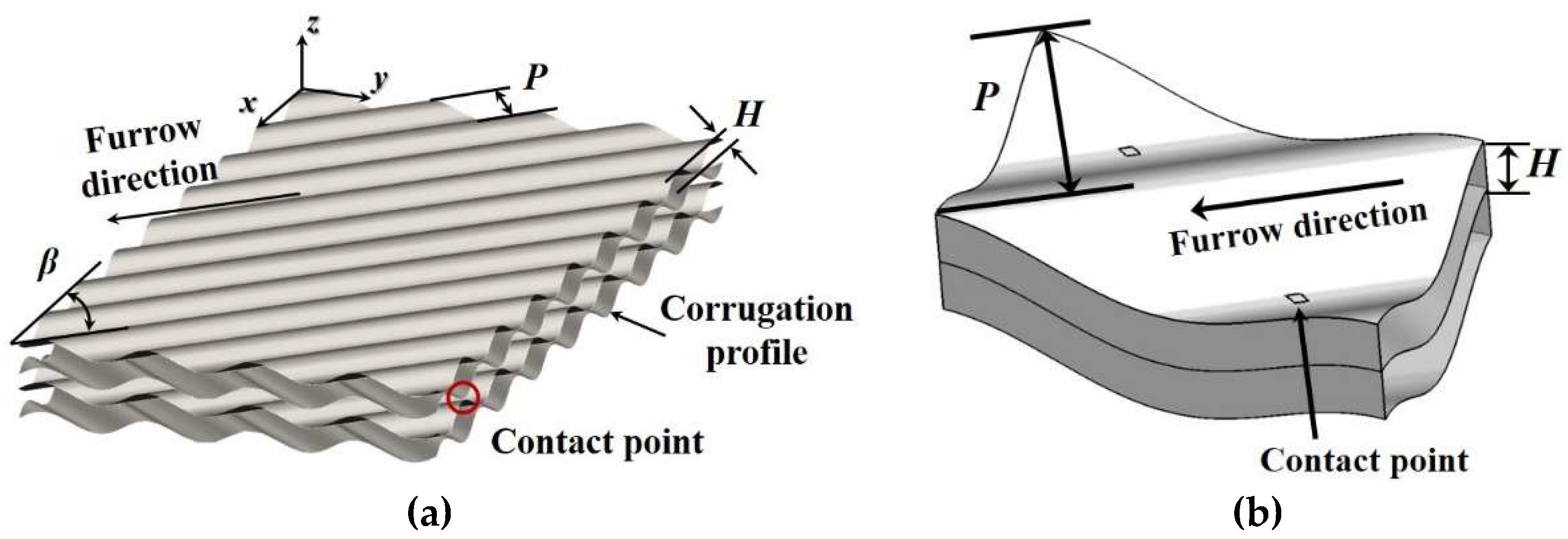
Figure 1. The configuration of the chevron shape of the plate heat exchanger: (a) partial plates and (b) a unitary cell repeated section with contact points in the flow channel.
Energies 13 01328 g001
Figure 2. Computational domain and grid system.
Energies 13 01328 g002
Figure 3. Corrugation configurations used in the present study.
Energies 13 01328 g003
Figure 4. Grid independence test results.
Energies 13 01328 g004
Figure 5. Comparison of the predicted averaged Nusselt number with the literature [9].
Energies 13 01328 g005
Figure 6. Streamlines in the hot water channel with the sinusoidal configuration.
Energies 13 01328 g006
Figure 7. Velocity magnitude distributions for various corrugation profiles at x = 0.0156 m.
Energies 13 01328 g007
Figure 8. Vorticity magnitude distributions with respect to corrugation profiles at x = 0.0156 m.
Energies 13 01328 g008
Figure 9. Flow motion according to the flow channel variation with triangular and elliptical corrugation profile at x = 0.013, 0.0143, 0.0156, 0.0169, and 0.0182 m.
Energies 13 01328 g009
Figure 10. Normalized vorticity distribution with respect to corrugation profiles for each flow direction along Line 1 for (a) sinusoidal, (b) trapezoidal, (c) triangular, and (d) elliptical corrugation profiles.
Energies 13 01328 g010
Figure 11. Streamwise vorticity distributions with respect to corrugation profiles: (a) at x = 0.0156 m and (b) along Line 1.
Energies 13 01328 g011
Figure 12. (a) Colburn j-factor and (b) friction factor for each corrugation profile according to the Reynolds number.
Energies 13 01328 g012
Figure 13. Heat transfer coefficient with respect to the pumping power per unit surface area for each corrugation profile.
Energies 13 01328 g013
Table 1. Solid properties [23].
ComponentStainless Steel
Density, ρs8030 kg/m3
Thermal conductivity, ks16.27 W/m∙K
Specific heat at constant pressure, Cp,s502.48 J/kg∙K