Abstract
High temperature superconducting (HTS) power cables are a potential solution for the grid integration of offshore wind farms since the HTS cable can conduct bulk wind power at low voltage levels. However, the transient current through the HTS cable in cases of low voltage ride through (LVRT) operation has a negative impact on the HTS cable operation due to the quenching phenomenon. This paper analyzes the impact of LVRT control strategies on the HTS cable operation. In addition, a coordinated control of wind turbines for LVRT improvement of an offshore wind farm is proposed. The feasibility of the HTS cable application for the grid connection of offshore wind farms is also discussed in this study. The proposed controller is designed for the wind turbine generator based on a type-4 permanent magnet synchronous generator. In the proposed controller, the transient current through the HTS cable is reduced by regulating the machine side power during fault conditions. The feasibility of the proposed controller is validated in the PSCAD/EMTDC program (Manitoba Hydro International Ltd., Winnipeg, Manitoba, Canada, version 4.2.1). The effects of transient current on the cable temperatures and resistances are analyzed in this study. Simulation results show that the proposed control strategy could reduce the transient current and temperature rise of the HTS cable.
1. Introduction
The high temperature superconducting (HTS) cable offers various advantages over the conventional cable, such as high-power capacity, low voltage operation, low impedance, and an integrated fault current limiter [1,2,3], which allows the HTS cable to carry large transmission capacity with more compact size and high efficiency. The HTS cable is primarily used for high load areas where the construction of an additional substation with major transformer assets is not feasible [4,5,6]. Another application of the HTS cable is to improve power transfer capability by connecting two existing substations where its transfer capacity limit is reached [7,8]. Recently, the use of the HTS cable for the grid connection of bulk offshore wind has been proposed.
The DC HTS cable in the high voltage direct current (HVDC) transmission of the offshore wind farm was proposed in [9], which brings the benefits of improving voltage stability and efficiency. The use of a medium voltage HTS cable for the grid connection of offshore wind farms could reduce a considerable power transfer loss [10]. The technical and economic evaluation of an HTS cable solution for the wind farm in [11] showed that the use of ±150 kV DC HTS transmission is a cost-competitive solution. In addition, using the medium voltage AC HTS cable for wind power transfer would reduce the capital cost of offshore wind farms due to the lack of high-power transformers and AC/DC converter systems. The feasibility of a short-length HTS cable for the grid connection of a large-scale wind farm was discussed in [12,13] since the number of offshore wind farms with a 10 km distance or less from the mainland will increase [14].
A technical challenge of using the HTS cable for wind farm application is to deal with the high transient current through the HTS cable during low voltage ride through (LVRT) operation of the wind farm system. Since the wind farm is required to stay connected to the utility grid in short periods of low voltage, various LVRT control strategies have been proposed. The crowbar protection is the most well-known approach to protect the wind turbine generator during fault condition [15,16,17]. The design of a high-power resistor in the crowbar protection should be considered carefully since resistor value has a negative impact on the stator current of a wind turbine generator. Energy storage systems (ESSs) connected with the DC-link capacitor were used to absorb the excess energy during fault condition [18,19,20], preventing overvoltage of the DC-link and improving the LVRT capability of the wind turbine generator (WTG). Fault current limiters (FCLs), which limit the transient current by changing these impedances, have been proposed to improve the LVRT capability [21,22,23]. In addition, coordinated control strategies of converters in WTG for LVRT improvement have been proposed [24,25].
Depending on the LVRT control strategies, the operation of the HTS cable could be affected by transient current during low voltage conditions. The quench of the HTS cable occurs when the transient current is higher than its critical current, resulting in the loss of a superconductivity state and the increase of cable temperature. It would take a long time to recover the superconductivity state if the temperature rise is significant, which causes a negative impact on the wind farm operation. Although the HTS cable is designed to sustain the high fault current for short periods, the LVRT control strategy should be designed with consideration of the HTS cable operation. The design of the LVRT control strategy considering the HTS cable operation is presented in this study. The main contributions of this study are listed as follows.
- ▪
- Analyze the impact of various LVRT control techniques on the HTS cable operation. Two LVRT control strategies are focused on this study, which are the crowbar protection and the coordinated control of WTG converters;
- ▪
- Propose an effective coordinated control to improve the LVRT performance of offshore wind farms connected to the grid by the HTS cable.
The offshore wind farm based on the permanent magnet synchronous generator (PMSG) is considered in this study. A detailed converter controller of PMSG-based WTG is presented. The simplified coaxial HTS cable model for transient studies adopted from [26] is used to evaluate the impact of LVRT strategies.
The rest of this paper is organized as follows. Section 2 describes the use of the HTS cable for the grid connection of offshore wind farms and the problem of the HTS cable under fault conditions. Section 3 explains the converter controller of WTG and the proposed coordination control to improve the LVRT performance. Simulation results in the PSCAD/EMTDC program (Manitoba Hydro International Ltd., Winnipeg, Manitoba, Canada, version 4.2.1) are discussed in Section 4. Finally, Section 5 summaries the conclusions of this study.
2. HTS Power Cable for Grid Connection of Offshore Wind Farm
The development of the offshore wind farm has been attracted more attention due to the restriction of the land availability for onshore installation. There are three techniques to conduct bulk wind power to the utility grid: high voltage direct current (HVDC), high voltage alternative current (HVAC), and HTS cable transmission, as shown in Figure 1. Conventionally, depending on the break-even distance, the high voltage direct current (HVDC) or high voltage alternative current (HVAC) transmission system is used to transfer wind power to the utility grid in which HVDC is suitable for the long transmission, whereas HVAC is a preferable solution for a short distance. The high capital cost of the HVDC transmission and high-power losses of the HVAC transmission are the limitations of the conventional methods for grid connection. With the fast development of the superconducting technique, the use of the HTS cable is a promising method for transmitting bulk wind power over short distances at low voltage levels. The HTS cables can transport much higher power than conventional cables with low power losses. The low impedance of the HTS cables not only reduces power losses but also improves the voltage profile in the connected power system [12].
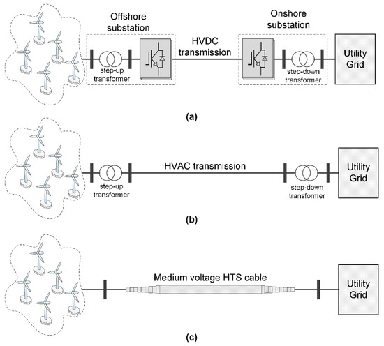
Figure 1.
Connecting offshore wind farm to utility grid: (a) high voltage direct current (HVDC) transmission; (b) high voltage alternative current (HVAC) transmission; (c) high temperature superconducting (HTS) cable.
The configuration of the wind turbine generator based on the permanent magnet synchronous generator is shown in Figure 2. When the fault occurs in the utility grid, the drop voltage leads to the increase of grid current to maintain constant power. However, the output current is limited by the capability of the back-to-back (BTB) converter, which results in the reduction of power injected to the grid (PG). Meanwhile, the wind power (PM) constantly maintains during the fault. According to the power balance in the WTG shown in Figure 2, the DC-link power of the BTB converter given by (1) increases gradually, resulting in an increase of DC-link voltage. The BTB converter should be shut down if the DC-link voltage increases significantly, leading to the interruption of WTG. Thus, the WTG controller should be designed properly to maintain the operation of WTG during fault conditions.
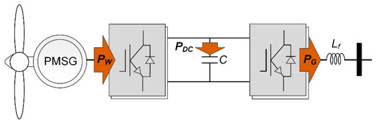
Figure 2.
Power flow of permanent magnet synchronous generator (PMSG)-based wind turbine generator.
The continuous wind power captured from the wind turbine (PM) causes a significant increase in grid current. In case the offshore wind farm connected to the grid by the HTS power cable, the total current through the HTS cable could exceed the critical current, resulting in the quenching condition. Consequently, recovering of HTS cable operation causes the interruption of wind farms. To solve the problem, this study proposes a coordinated control of WTG to improve the LVRT performance, considering the characteristic of the HTS power cable.
3. Converter Controller for LVRT Improvement
3.1. Converter Controller of Type-4 PMSG Wind Turbine Generator
A typical configuration of the type-4 WTG based on PMSG is shown in Figure 3 in which the BTB converter is used to control the WTG, and the step-up transformer is used to connect the WTG to the grid. The BTB converter consists of two converters: machine side converter (MSC) and grid side converter (GSC). The GSC, which connects to the step-up transformer through the inductance filter (Lf), is in charge of regulating the DC-link voltage of the BTB converter. The MSC connecting with the PMSG is responsible for the speed or torque control of WTG. In addition, the pitch angle control is also used to maintain the WTG operation under extreme wind speed.
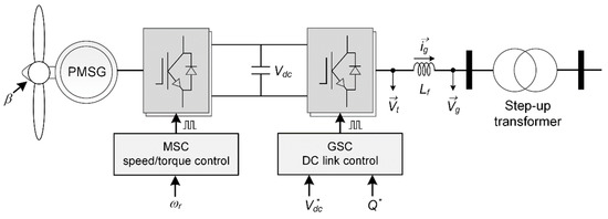
Figure 3.
Configuration of type-4 PMSG-based wind turbine generator.
The MSC and GSC are based on the three-phase two-level voltage source converter, which consists of two insulated-gate bipolar transistors (IGBTs) in each phase. Neglecting the internal resistance of IGBTs, the dynamic equation of the GSC is described by the following space phasor equation.
where is the inductance filter; is the space phasor of the terminal GSC voltage; is the space phasor of the output filter voltage; and is the space phasor of the grid current.
Considering the representation of the space phasor in the dq-reference frame, , the dynamic Equation (3) could be represented in the real and imaginary components, as given by
where and are the dq-axis components of the terminal GSC voltage; and are the dq-axis components of the output filter voltage; and are the dq-axis components of the filter current; is the angle of the space phasor of the grid voltage.
Since the phase-locked loop (PLL) mechanism is used to regulate at , (4) and (5) can be given by
where is the grid angular frequency; is the initial angle of the grid voltage.
The dq-axis components of the GSC terminal voltage ( and ) are linearly proportional to the modulating signals ( and ) with the proportionality constant of , as given by
Due to the presence of terms in (6) and (7), dynamics of dq-current () are coupled. The modulation signal is defined by (10) and (11) to decouple the dynamics.
where and are the new control inputs.
Substituting for and in (8) and (9), then substituting for and in (6) and (7), we have
It can be seen in (12) and (13) that the output dq-axis components () of grid current can be controlled by and . The proportional–integral (PI) regulators are used to generate the control signals and as follows
where , , , and are the parameters of the PI regulators; and are the current references.
Substituting the control signals and uq from (14) and (15) in (10) and (11), respectively, we have
The current references and are provided by the outer DC-voltage/reactive power control loops, as given by.
where , , , and are the parameters of the PI regulators; is the measured DC-link voltage of the BTB converter; is the reference DC-link voltage; is the measured output reactive power; is the reference output reactive power.
Based on (16) to (19), the block representation of the GSC controller is shown in Figure 4a.
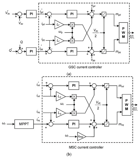
Figure 4.
Back-to-back converter controllers: (a) grid side converter (GSC) controller; (b) machine side converter (MSC) controller.
The dynamics voltage equations of the PMSG expressed in the dq-reference frame is given by
where is the stator resistance; is the rotor angular frequency; is the magnet flux of PMSG; and are the dq-axis components of the stator current; and are the dq-axis components of the stator inductances; and are the dq-axis components of the stator voltage that are proportional to the modulation signals ( and ), as in (22) and (23).
It also can be seen that the dq-stator currents of PMSG are coupled due to the presence of and terms. The modulation signal given by (24) and (25) is introduced to decouple the dynamics.
where and are the control inputs, which are generated by the PI regulators, as follows
where , , , and are the parameters of the PI regulators; and are the current references provided by the outer control loop.
Substituting the control inputs from (26) and (27) in (24) and (25), we have
Figure 4b shows a block representation of the MSC controller based on (28) and (29), which includes the current control and maximum power point tracking (MPPT) control loops. In the current control loop, the current reference is set equal to zero and is given by (30).
where is the number of pole pairs; is the optimal torque reference from the MPPT controller.
The tip speed ratio based MPPT is used in this study, as given by (31).
where is the turbine swept area; is the air mass density; is the turbine blade radius; is the maximum performance coefficient; is the optimal tip-speed ratio when the blade pitch angle is equal to zero ().
3.2. LVRT Control Strategies
Figure 5 shows the typical configuration of the LVRT control strategy using the crowbar protection, which consists of a high-power resistor and a switch connected in parallel with the DC-link capacitor of the BTB converter. When the fault occurs on the grid side, the excess active power of WTG is dissipated in the high-power resistor. The duty ratio of the crowbar switch is controlled by the dead-band control to maintain the DC-link voltage.
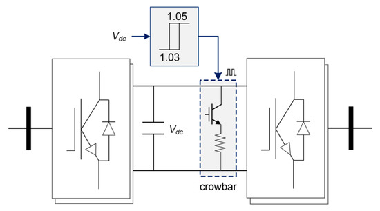
Figure 5.
Crowbar protection for low voltage ride through (LVRT) of wind turbine generator.
The MSC controller is designed with the de-loading technique in [27] to improve the LVRT operation of the WTG, as shown in Figure 6. The q-axial current reference of the MSC is multiplied with the droop DC-link voltage. The reference current is reduced when the DC-link voltage increases, which reduces the machine side power and the DC-link voltage during fault condition.
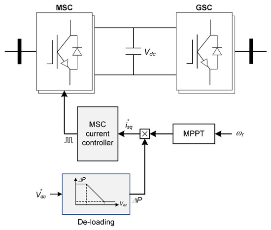
Figure 6.
De-loading control for LVRT of wind turbine generator.
Figure 7 shows an overall control diagram of the PMSG for LVRT improvement. Normally, the LVRT switch is in state 0 to capture maximum wind power, whereas GSC controls the DC-link voltage. The state of the LVRT switch is changed from 0 to 1 when the voltage sag or fault is detected. In this condition, the MSC controller is changed from the power controller to the DC-link voltage controller and the GSC controller is disabled. The proposed controller aims to reduce wind power PM and stably regulates the DC-link voltage at the nominal value during fault condition, resulting in the reduction of the HTS cable current. The operation of wind farms would be quickly recovered since the quenching phenomenon of the HTS cable does not occur. The root mean square (RMS) current of output filter Lf and voltage are measured to activate the proposed controller, as given by (33).
where is the turns ratio of the step-up transformer; is the critical current of the HTS power cable; is the number of WTGs in the wind farm; is the grid drop voltage;
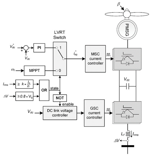
Figure 7.
Proposed coordinated LVRT controller considering the HTS power cable characteristic.
4. Simulation
4.1. System Description
The tested offshore wind farm system connected to the grid by the HTS cable is shown in Figure 8, which consists of three radial feeders with two WTGs in each feeder. Three feeders are connected to the point of common coupling (PCC) and the offshore wind power is transferred to the utility grid by the 22.9 kV HTS power cable. The normal 22.9 kV cable with a length of 2 km is used to connect WTGs. The tested system is modeled in the PSCAD/EMTDC program. The normal cable is modeled by a series resistor/inductor (R/L) impedance. Detailed parameters of PMSG are shown in Table 1.
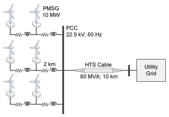
Figure 8.
Tested offshore wind farm connected to grid by the HTS power cable with the critical current () of 5 kA.

Table 1.
PMSG parameters.
The coaxial multilayer HTS power cable used in this study is shown in Figure 9 in which each phase consists of the HTS layer and copper (Cu) former layer. The purpose of using the Cu-former layer in each phase is to protect the HTS layer from burning out at the transient state. The current flow in each layer is depended on the operating state of the HTS cable, as shown in Figure 10a. At normal conditions, since the impedance of the Cu-former layer is much higher than that of the HTS layer, the current mainly flows through the HTS layer. At the transient state, the fault current through the HTS cable rapidly increases. If the transient current exceeds the critical current of the HTS cable, a quench in the HTS layer occurs, leading to a significant increase of HTS layer impedance. In this condition, the value of HTS layer impedance is much higher than the Cu-former impedance. Thus, the transient current flows mainly through the Cu-former layer. Modeling of the HTS cable in the PSCAD/EMTDC program is shown in Figure 10b, which includes the variable resistors and self/mutual inductors. Detailed modeling of the coaxial HTS cable is described in [26].
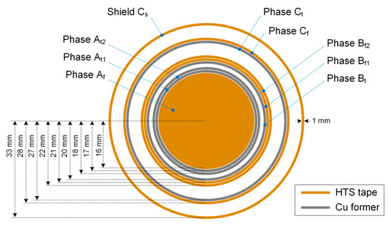
Figure 9.
Configuration of the coaxial multilayer HTS power cable.
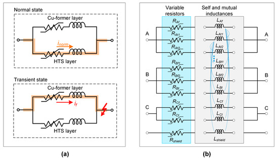
Figure 10.
Coaxial multilayer HTS cable model: (a) operating characteristic; (b) HTS cable model in the PSCAD/EMTDC program consisting the variable resistors and self/mutual inductors adopted from [26].
4.2. Simulation Results
The performance of the coordinated controller is compared to the crowbar protection and de-loading schemes to illustrate the effectiveness of the proposed strategy. With the constant wind speed of 11.4 m/s, each WTG produces 10 MW of wind power output. It is assumed that the fault at the utility grid side occurs at 1 s and it is cleared after 0.5 s.
The DC-link voltage of the BTB converter in the WTG1 is shown in Figure 11. During the fault condition, the dead-band control in the case of crowbar protection maintains the DC-link voltage between 1.05 pu and 1.03 pu. The DC-link voltage in the case of de-loading control increases significantly compared to other methods due to the slow response of droop DC-link regulation. The proposed control strategy regulates the DC-link voltage at the normal value although the transient DC-link voltage is high. When the grid fault is cleared, the DC-link voltage is recovered to its nominal value. It can be seen that the response of DC-link voltage under the proposed control is quicker than that of crowbar protection. The q-axis stator current () is shown in Figure 12 in which the reference q-axis stator current () was generated by the MPPT controller in the normal condition and the DC voltage controller in the fault condition. It can be seen that the seamless transition of MPPT control and DC-link voltage control occurs at 1 s and 1.5 s.
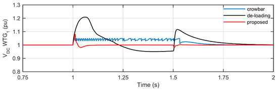
Figure 11.
DC-link voltage of back-to-back (BTB) converter of wind turbine generator (WTG)1.
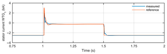
Figure 12.
Stator current of WTG1 in q-axis.
The output power of WTG1 and total wind farm power injected to the utility grid are shown in Figure 13. The grid fault causes the reduction of output wind power and the wind power is recovered to the normal values at 1.5 s. In the case of using the proposed controller, the machine side power (PM) is reduced during fault condition. In addition, the power balance of the BTB converter is maintained by regulating the DC-link voltage at the nominal value, resulting in a small amount of output wind power.
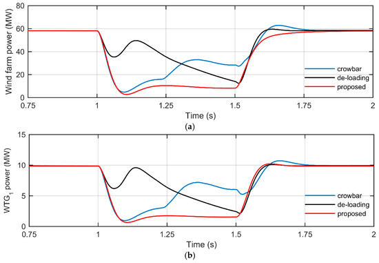
Figure 13.
Output powers: (a) output power of WTG1; (b) output power of offshore wind farm.
Three-phase currents through the HTS power cable are shown in Figure 14. It can be seen that the current through the HTS power cable in case of using the crowbar protection significantly increases during fault condition. The maximum transient current is 5.656 kA, which is higher than the critical current of the HTS cable ( kA), resulting in the quench of the HTS cable. The quench of the HTS cable in case of using the crowbar protection leads to the increases of cable temperatures and resistances, as shown in Figure 15a and Figure 16a. The highest temperature rise is found in the former phase C with the value of 70.83 K. The quench of the HTS cable also occurs in case of using de-loading control, as shown in Figure 15b, where the cable temperature increases slightly. By comparison, the HTS cable current during fault is much smaller in case the proposed controller is used. The maximum transient current, in this case, is 4.122 kA, which is lower than the critical current of the HTS cable. Thus, the quench of the HTS power cable does not occur in this case. It can be seen that the cable temperatures and resistances in Figure 15b and Figure 16b do not change in the fault condition.
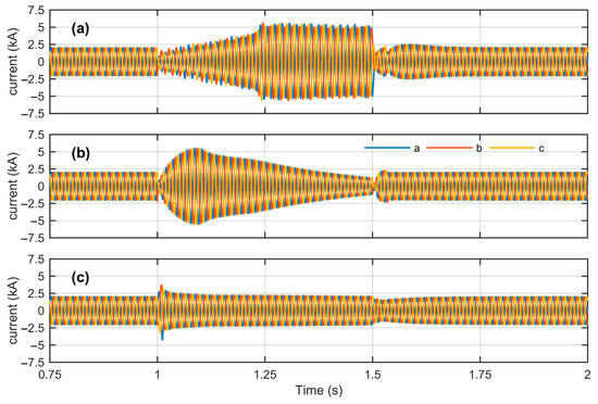
Figure 14.
Three-phase current through the HTS power cable: (a) crowbar protection; (b) proposed control strategy; (c) de-loading control.
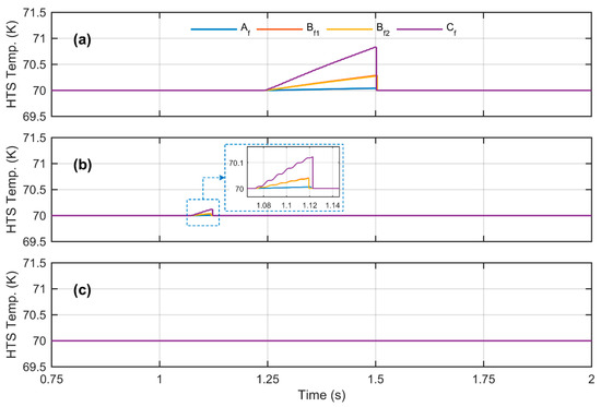
Figure 15.
Temperature of HTS cable former during fault: (a) crowbar protection; (b) proposed control strategy; (c) de-loading control.
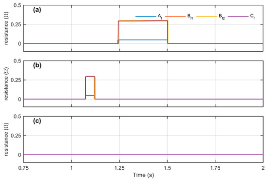
Figure 16.
Resistance of HTS cable former during fault: (a) crowbar protection; (b) proposed control strategy; (c) de-loading control.
5. Conclusions
The impacts of LVRT control strategies of the offshore wind farm on the HTS power cable has been discussed in this study. Simulation results have shown that the high transient current in case of using crowbar protection and de-loading controls resulted in the quench of the HTS cable. Depending on the transient current, the HTS cable temperature could significantly increase. The wind farm could be disconnected from the utility grid since the HTS cable has to be cooled down to recover the superconducting state. The coordinated control of WTG considering the characteristic of the HTS cable was proposed to solve the problem. The aim of the proposed controller is to reduce the wind power captured from wind turbines and to maintain the DC-link voltage during fault condition. It was observed that the transient current in the case of using the proposed controller is much lower than that of crowbar protection. Since the magnitude of the transient current is lower than the critical current, the quench of the HTS cable did not occur, resulting in the stable operation of the wind farm system and the HTS cable.
This paper presented the time-domain analysis of the offshore wind farm with the HTS cable under transient conditions since it directly analyzes the impact of LVRT control on the HTS cable performance. In addition to the time-domain analysis, considering the analytical method based on the frequency-domain analysis would be an interesting topic for our future studies.
Author Contributions
Conceptualization, investigation, and writing—original draft preparation, T.-T.N.; writing—review & editing and supervision, H.-M.K.; funding acquisition, H.S.Y. All authors have read and agreed to the published version of the manuscript.
Funding
This research was funded by the Korea Electric Power Corporation.
Acknowledgments
This research was supported by the Research Assistance Program (2019) in the Incheon National University.
Conflicts of Interest
The authors declare no conflict of interest.
Nomenclature
| Abbreviations | |
| HTS | High temperature superconducting |
| FCL | Fault current limiter |
| ESS | Energy storage system |
| LVRT | Low voltage ride through |
| WTG | Wind turbine generator |
| BTB | Back-to-back converter |
| IGBT | Insulated-gate bipolar transistor |
| MSC | Machine-side converter |
| GSC | Grid-side converter |
| PMSG | Permanent magnet synchronous generator |
| PCC | Point of common coupling |
| RMS | Root mean square |
| MPPT | Maximum power point tracking |
| PLL | Phase-locked loop |
| Parameters | |
| Critical current of HTS cable | |
| Power change due to DC-link voltage drop | |
| DC-link power | |
| MSC power | |
| GSC power | |
| DC-link voltage | |
| DC-link voltage reference | |
| Space phasor | |
| Space phasor of grid current | |
| ; | dq-axis components of grid current |
| ; | dq-axis components of grid current reference |
| ; | dq-axis components of stator current reference |
| Space phasor of output filter voltage | |
| ; | dq-axis components of output filter voltage |
| Space phasor of terminal GCS voltage | |
| ; | dq-axis components of the terminal GSC voltage |
| ; | dq-axis components of the stator voltage |
| ; | dq-axis components of modulating signals of GSC |
| ; | dq-axis components of control inputs for the GSC |
| ; | dq-axis components of modulating signals of MSC |
| ; | dq-axis components of control inputs for the MSC |
| RMS current of GSC | |
| Voltage drop | |
| DC-link capacitor | |
| Inductance filter | |
| Grid angular frequency (rad/s) | |
| Rotor angular frequency (rad/s) | |
| Measured reactive power | |
| Reference reactive power | |
| Optimal torque reference | |
| Number of pole pairs | |
| Magnet flux of PMSG | |
| Angle of the space phasor | |
| Initial phase angle of grid voltage | |
| ; | dq components of stator inductance |
| Stator resistance of PMSG | |
| Turns ratio of the step-up transformer | |
| Number of WTGs in offshore wind farm | |
| Wind turbine parameters | |
| Optimal tip-speed ratio | |
| Turbine swept area | |
| Air mass density | |
| Turbine blade radius | |
| Maximum performance coefficient | |
| Pitch angle |
References
- Yang, B.; Kang, J.; Lee, S.; Choi, C.; Moon, Y. Qualification Test of a 80 kV 500 MW HTS DC Cable for Applying Into Real Grid. IEEE Trans. Appl. Supercond. 2015, 25, 1–5. [Google Scholar] [CrossRef]
- Doukas, D.I.; Syrpas, A.; Labridis, D.P. Multiterminal DC Transmission Systems Based on Superconducting Cables Feasibility Study, Modeling, and Control. IEEE Trans. Appl. Supercond. 2018, 28, 1–6. [Google Scholar] [CrossRef]
- Ren, L.; Tang, Y.; Shi, J.; Li, A.; Li, J.; Cheng, S. Techno-economic feasibility study on hts power cables. IEEE Trans. Appl. Supercond. 2009, 19, 1774–1777. [Google Scholar] [CrossRef]
- Yoon, J.Y.; Lee, S.R.; Kim, J.Y. Application Methodology for 22.9 kV HTS Cable in Metropolitan City of South Korea. IEEE Trans. Appl. Supercond. 2007, 17, 1656–1659. [Google Scholar] [CrossRef]
- Li, J.; Zhao, Z.; Shu, B.; Han, X.; Ma, X.; Bian, B.; Li, J.; Liang, Z. Fault Analysis for 110 kV HTS Power Cables. IEEE Trans. Appl. Supercond. 2014, 24, 1–5. [Google Scholar] [CrossRef]
- Dinh, M.-C.; Ju, C.-H.; Kim, J.-G.; Park, M.; Yu, I.-K.; Yang, B. Transient analysis of an HTS DC power cable with an HVDC system. Phys. C Supercond. 2013, 494, 311–318. [Google Scholar] [CrossRef]
- Sytnikov, V.E.; Bemert, S.E.; Kopylov, S.I.; Romashov, M.A.; Ryabin, T.V.; Shakaryan, Y.G.; Lobyntsev, V.V. Status of HTS Cable Link Project for St. Petersburg Grid. IEEE Trans. Appl. Supercond. 2015, 25, 1–4. [Google Scholar] [CrossRef]
- Lee, S.J.; Park, M.; Yu, I.-K.; Won, Y.; Kwak, Y.; Lee, C. Recent Status and Progress on HTS Cables for AC and DC Power Transmission in Korea. IEEE Trans. Appl. Supercond. 2018, 28, 1–5. [Google Scholar] [CrossRef]
- Østergaard, J.; Tønnesen, O.; Kaas-Pedersen, J.; Nielsen, A.H.; Træholt, C. A new concept for superconducting DC transmission from a wind farm. Phys. C Supercond. 2002, 372–376, 1560–1563. [Google Scholar] [CrossRef]
- Morandi, A. HTS dc transmission and distribution: Concepts, applications and benefits. Supercond. Sci. Technol. 2015, 28, 123001. [Google Scholar] [CrossRef]
- Morandi, A.; Gholizad, B.; Stieneker, M.; Stagge, H.; De Doncker, R.W. Technical and Economical Evaluation of DC High-Temperature Superconductor Solutions for the Grid Connection of Offshore Wind Parks. IEEE Trans. Appl. Supercond. 2016, 26, 1–10. [Google Scholar] [CrossRef]
- Yoon, D.-H. A Feasibility Study on HTS Cable for the Grid Integration of Renewable Energy. Phys. Procedia 2013, 45, 281–284. [Google Scholar] [CrossRef][Green Version]
- Geschiere, A.; Willén, D.; Piga, E.; Barendregt, P. HTS cables open the window for large-scale renewables. J. Phys. Conf. Ser. 2008, 97, 012183. [Google Scholar] [CrossRef]
- Endo, N.; Shinozaki, Y.; Nagasaki, Y.; Miyagi, D.; Tsuda, M. Configuration Method of Tri-Axial ReBCO Cable Suitable for Long Distance Power Transmission. IEEE Trans. Appl. Supercond. 2019, 29, 1–5. [Google Scholar] [CrossRef]
- Monteiro Pereira, R.; Pereira, A.; Ferreira, C.; Barbosa, F. Influence of Crowbar and Chopper Protection on DFIG during Low Voltage Ride Through. Energies 2018, 11, 885. [Google Scholar] [CrossRef]
- Long, T.; Shao, S.; Malliband, P.; Abdi, E.; McMahon, R.A. Crowbarless Fault Ride-Through of the Brushless Doubly Fed Induction Generator in a Wind Turbine Under Symmetrical Voltage Dips. IEEE Trans. Ind. Electron. 2013, 60, 2833–2841. [Google Scholar] [CrossRef]
- Din, Z.; Zhang, J.; Zhu, Y.; Xu, Z.; El-Naggar, A. Impact of Grid Impedance on LVRT Performance of DFIG System With Rotor Crowbar Technology. IEEE Access 2019, 7, 127999–128008. [Google Scholar] [CrossRef]
- Guo, W.; Xiao, L.; Dai, S. Enhancing Low-Voltage Ride-Through Capability and Smoothing Output Power of DFIG With a Superconducting Fault-Current Limiter–Magnetic Energy Storage System. IEEE Trans. Energy Convers. 2012, 27, 277–295. [Google Scholar] [CrossRef]
- Guo, W.; Xiao, L.; Zhang, G.; Zhang, J.; Song, N.; Gao, Z.; Xu, X.; Jing, L.; Teng, Y.; Zhu, Z. Development of a 1-MVA/1-MJ Superconducting Fault Current Limiter–Magnetic Energy Storage System for LVRT Capability Enhancement and Wind Power Smoothing. IEEE Trans. Appl. Supercond. 2018, 28, 1–5. [Google Scholar] [CrossRef]
- Shen, Y.-W.; Ke, D.-P.; Qiao, W.; Sun, Y.-Z.; Kirschen, D.S.; Wei, C. Transient Reconfiguration and Coordinated Control for Power Converters to Enhance the LVRT of a DFIG Wind Turbine With an Energy Storage Device. IEEE Trans. Energy Convers. 2015, 30, 1679–1690. [Google Scholar] [CrossRef]
- Lee, H.-J.; Lim, S.-H.; Kim, J.-C. Application of a Superconducting Fault Current Limiter to Enhance the Low-Voltage Ride-Through Capability of Wind Turbine Generators. Energies 2019, 12, 1478. [Google Scholar] [CrossRef]
- Choi, S.-J.; Lim, S.-H. Enhancement on the Fault Ride through Capability of Power Distribution Systems Linked by Distributed Generation due to the Impedance of Superconducting Fault Current Limiters. Energies 2019, 12, 4810. [Google Scholar] [CrossRef]
- Alam, M.; Abido, M.; El-Amin, I. Fault Current Limiters in Power Systems: A Comprehensive Review. Energies 2018, 11, 1025. [Google Scholar] [CrossRef]
- Li, X.-M.; Zhang, X.-Y.; Lin, Z.-W.; Niu, Y.-G. An Improved Flux Magnitude and Angle Control With LVRT Capability for DFIGs. IEEE Trans. Power Syst. 2018, 33, 3845–3853. [Google Scholar] [CrossRef]
- Tripathi, S.M.; Tiwari, A.N.; Singh, D. Low-voltage ride-through enhancement with the ω and T controls of PMSG in a grid-integrated wind generation system. IET Gener. Transm. Distrib. 2019, 13, 1979–1988. [Google Scholar] [CrossRef]
- Nguyen, T.; Lee, W.-G.; Lee, S.; Park, M.; Kim, H.; Won, D.; Yoo, J.; Yang, H.S. A Simplified Model of Coaxial, Multilayer High-Temperature Superconducting Power Cables with Cu Formers for Transient Studies. Energies 2019, 12, 1514. [Google Scholar] [CrossRef]
- Mahela, O.P.; Gupta, N.; Khosravy, M.; Patel, N. Comprehensive Overview of Low Voltage Ride Through Methods of Grid Integrated Wind Generator. IEEE Access 2019, 7, 99299–99326. [Google Scholar] [CrossRef]
© 2020 by the authors. Licensee MDPI, Basel, Switzerland. This article is an open access article distributed under the terms and conditions of the Creative Commons Attribution (CC BY) license (http://creativecommons.org/licenses/by/4.0/).