1. Introduction
In the last two decades of the 20th century, magnetic materials based on rare earth materials with a high energy density were introduced into production on a massive scale. Materials of this type are characterized by better magnetic, mechanical and thermal properties in comparison with the types of hard magnetic previously materials used in the construction of electric machines. Therefore, a dynamic development in new permanent magnet machine designs has been observed for several years. In contemporary drive systems, electric machines such as synchronous motors (PMSM), brushless DC motors and hybrid stepper motors are used increasingly often [
1,
2,
3]. Currently, even motors with power given in megawatts are manufactured [
4]. The development of permanent magnet motors goes hand in hand with the development of the power supply converter and advanced control algorithms.
PMSM must be powered by the inverter system, which increases the total cost of the propulsion system. In recent years, an interesting alternative for PMSM has been permanent magnet (PM) motors with self-starting ability, so-called line-start permanent magnet motors. The basic advantage of the LSPMSM is the possibility of direct start-up after connecting to a three-phase grid.
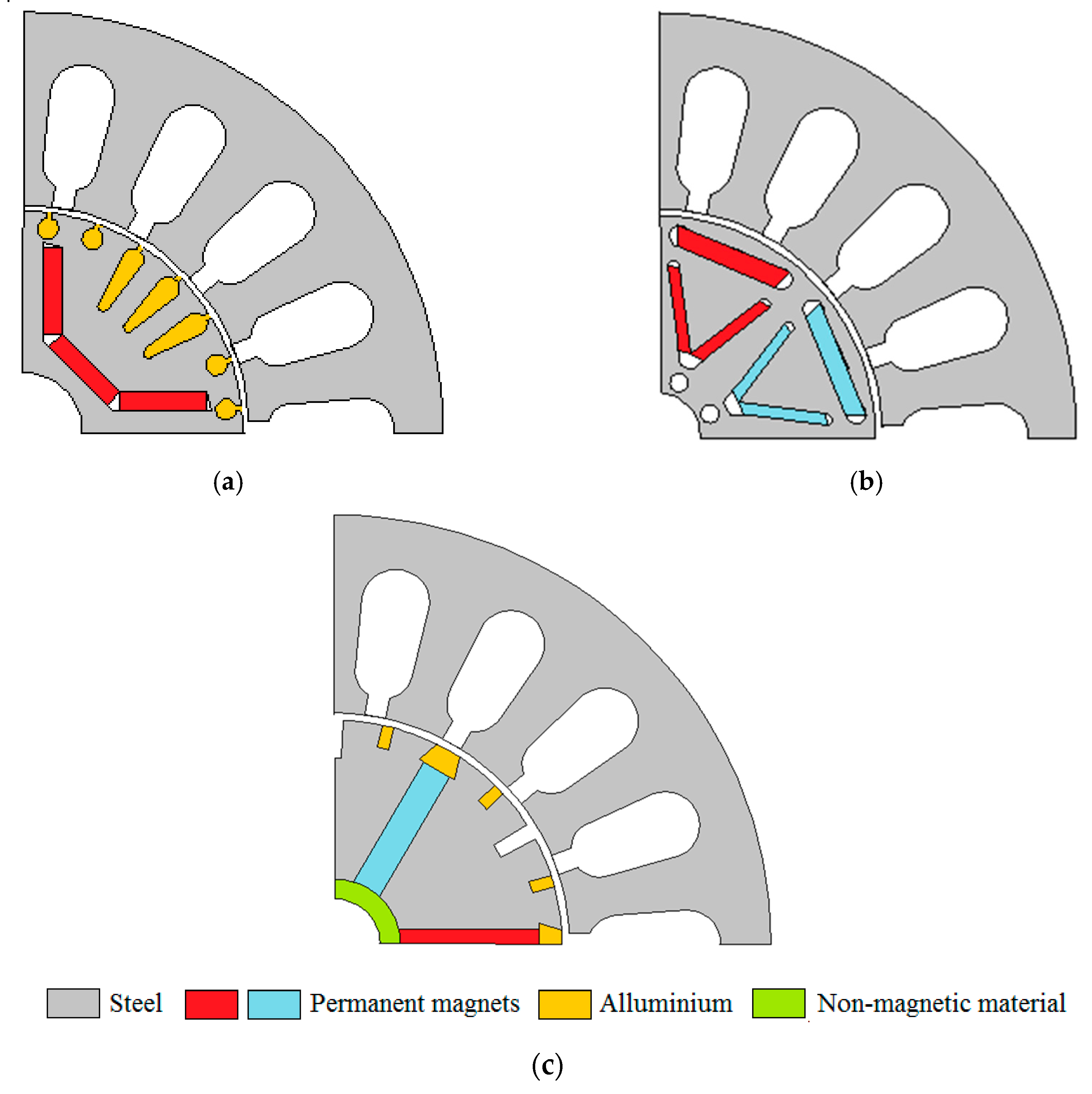
Figure 1 presents the new design of different PM motors [
5,
6,
7].
As new hard and soft magnetic materials are developed, innovative synchronous machine designs with permanent magnets are beginning to appear [
8]. Their aim is to improve the functional parameters, characteristics and economic indicators, i.e., to reduce production and operational costs. The new designs are often more difficult to construct technologically [
5]. Therefore, powder technology, which consists of manufacturing soft magnetic materials and forming permanent magnets, is used very often [
9].
The further development of new designs of permanent magnet motors depends on the improvement of methods of simulating their operating conditions as well as methods of design and optimization. In the contemporary process of designing of electromechanical devices and systems, computer simulations are used [
10]. The FEA (Finite Element Analysis) method is very popular and commonly used in the design and optimization process [
6,
11,
12]. It allows the costly and time-consuming stage of construction of prototypes to be avoided. Simulation tools provide the designer with the possibility of a virtual “implementation” and verification of their ideas, already at the design stage, which significantly shortens the period of implementation of new projects. The costs of producing subsequent prototypes of the designed machine are also reduced.
In the last decade, non-deterministic algorithms based on observations of the natural environment (nature-inspired algorithm [
13]) have been intensively developed. Scientists are still proposing new, more efficient optimization algorithms. These algorithms are based on the observation of animal behavior. This group includes: the Cuckoo Search Algorithm, the Bat Algorithm, the Particle Swarm Algorithm, the Grasshopper Optimization Algorithm and also the Gray Wolf Optimizer.
The aim of this paper was to design a low-power line-start synchronous motor. A stator for the serially manufactured low-power induction motor was used. The structural parameters of the permanent magnets and selected parameters of the rotor were optimized. In-house computer software supporting the design process of LSPMSM was developed. The software consists of two independent modules: (a) the FEA model of LSPMSM and (b) the optimization procedure. In the optimization procedure, the gray wolf method was applied [
14]. Four design variables, which describe the excitation system, have been taken into consideration.
In this paper, the optimization method and design of low-power line-start permanent magnet motor is presented. The structures of the base IM and designed LSPMSM are shown in
Section 2. Then, the gray wolf optimization method is described. In
Section 4, the formulation of the optimization task is discussed. Furthermore, experimental validation of the LSPMSM prototype is demonstrated in
Section 5. Finally, conclusions are drawn in
Section 6.
3. The Gray Wolf Optimization Method
The gray wolf optimization (GWO) method was developed on the basis of hunting techniques used by wolves in 2014 [
15]. The GWO method can be very effective in comparison to other non-deterministic optimization methods [
16]. The optimization process is the result of an interaction between individuals, which try to look for prey together. A wolf pack usually consists of several individuals in their natural environment. The pack leader, individual α, is the best-adapted individual in the pack. In the wolf pack’s organization, a very extensive system of social rungs is observed. The most important individual is the α. The alternative leader of the pack is the β individual. The third level in the hierarchy comprises δ individuals. The rest of the individuals in the algorithm are called ω individuals. These individuals represent the lowest level in the pack hierarchy. The positions of each ω individual are determined on the basis of position of the α, β and δ in each discrete time step [
17]. The hunting process of a gray wolf can be divided into several stages: (a) the stage of searching for the prey, (b) the stage of the chase, (c) the stage of encircling the prey and (d) the stage of the attack [
14].
In the mathematical model of the GWO method, the discrete position of each ω individual is determined in the subsequent iterations. The vector of positions of the
i-th individual in the
k-th iteration is calculated as follows:
Vectors X
1[1, 2, …,
n], X
2[1, 2, …,
n] and X
3[1, 2, …,
n] in Equation (1) are closely related to the position of the α, β and δ individuals in the area of the solved optimization task, where
n is the number of design variables in the optimization process. In the GWO method, the value of X
1, X
2 and X
3 can be expressed as in the formula below,
where
,
and
are the vectors of positions of α, β and δ in the previous iteration of the algorithm,
,
and
are the random control parameters of the GWO method.
The values of variables
,
and
in the gray wolf method represent the distance between the wolf under consideration and the leaders of the wolfpack (individuals α, β and δ) and can be determined using the formula,
where
C1,
C2and
C3 are the coefficient of the GWO method.
The value of coefficients
C changed randomly regardless of the locations of the remaining individuals in the pack. These coefficients are determined randomly for each individual and are calculated as follows:
where
r1,
r2 and
r3 are the random numbers from range (0, 1).
In each iteration of the method, it is necessary to determine the actual value of parameter
A. The control parameters
A determine the ability of the wolves to move in the area of the task [
18]. Adopting large values for
A, the ω individuals are very mobile and can freely move. A low value of this parameter makes the algorithm a local search properties algorithm. In the algorithm developed below, the values of the coefficients
and
are calculated as follows:
In the gray wolf method, the value of coefficient
a is determined for each iteration. This factor usually decreases linearly [
19]. In the proposed algorithm, the value of coefficient
a is determined for each iteration according to formula [
20].
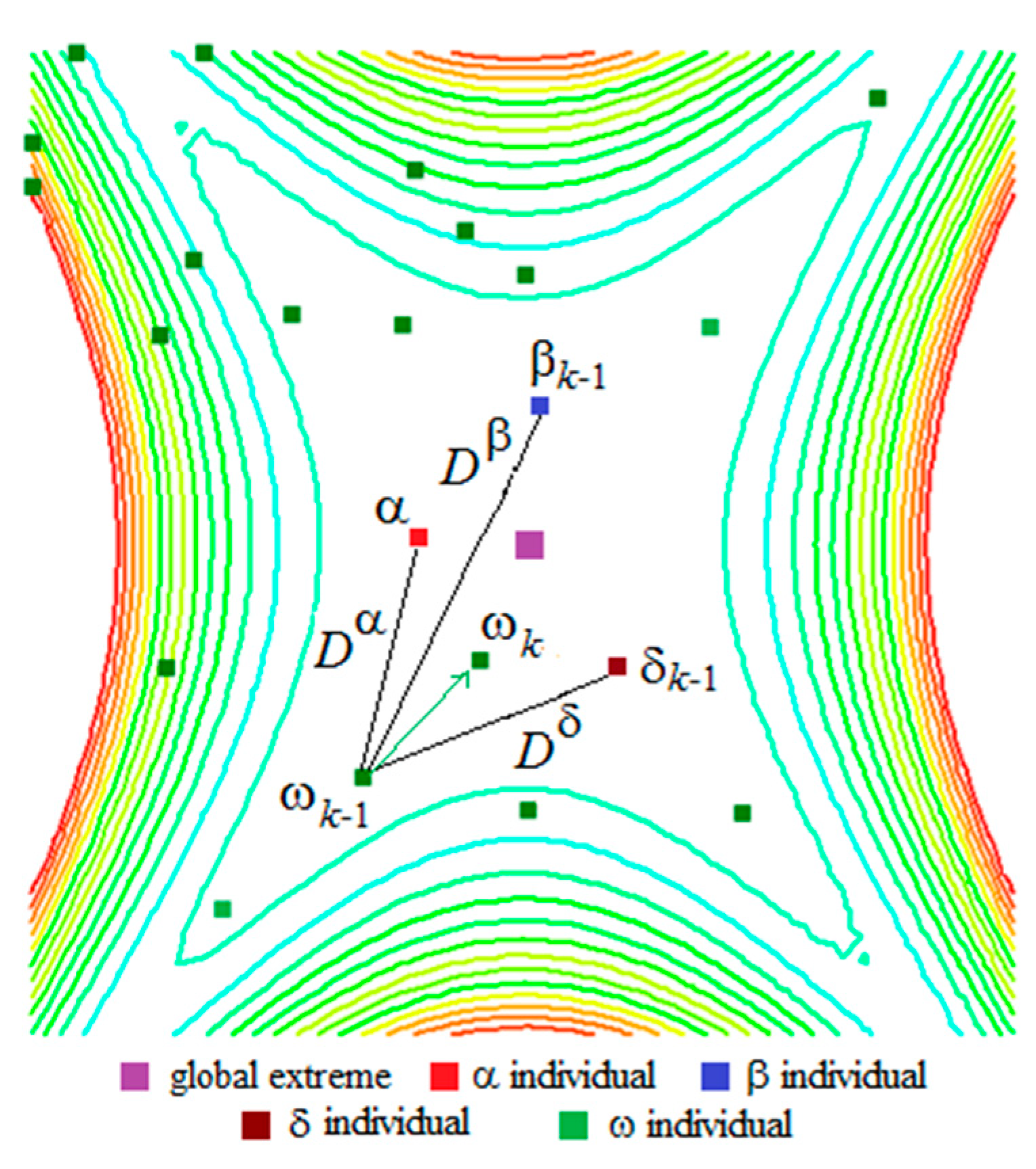
During successive iteration of the optimization process, the global extreme is surrounded by virtual wolves. The best positions are ensured tothe α, β and δ individuals (see
Figure 3). The rest of the individuals update their position according to the reference positions for α, β and δ. The determination of the new positions of the random ω positions are shown in
Figure 3.
4. Formulation of the Design Problem
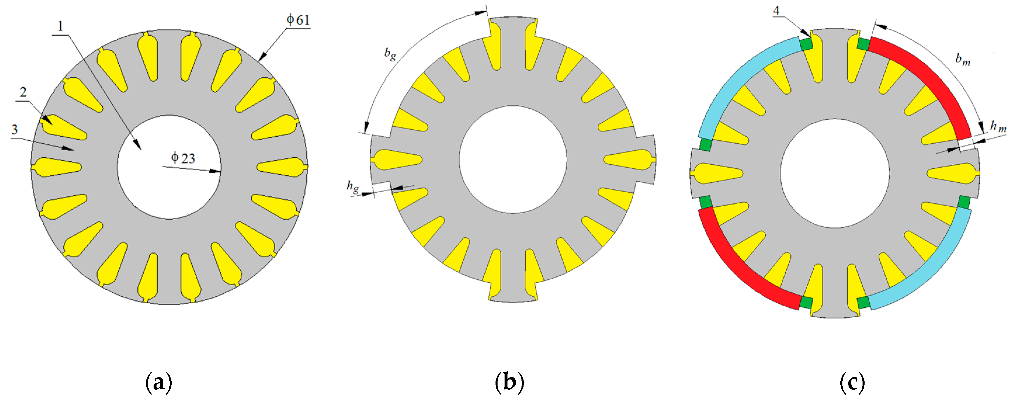
The purpose of the optimization was to determine the dimensions (see
Figure 2) of the permanent magnet (
bm and
hm), relative span (
bg) and dept of milled gaps (
hg) in the rotor, which will ensure better operational parameters of designed LSPMSM in comparison to IM. During optimization calculation only selected parameters of the rotor geometry were changed. All stator dimensions remain constant over optimization process.
Four design variables have been assumed (see
Figure 2):
s1 = α
g =
bg/τ—the relative span of milled gap in rotor,
s2 = ξ =
hb/
hm—relative dept of milled gap in rotor,
s3 =
hm—thickness of the permanent magnet,
s4 = α
m =
bm/τ—relative span of the permanent magnet, where τ is the pole pitch. The design variables form the vector s = [α
g, ξ,
hm, α
m]
T. The ranges of change for all design variables are given in
Table 2.
Very often the normalization of design variables is performed to standardize their value in the optimization process. The purpose of the normalization is to make design variables comparable. The design variables
sjis converted into dimensionless quantities
xj according to the relationship
where
and
are the lower and upper limits of each variable
sj, respectively.
An optimum design is focused on the rotor structure construction and is aimed at improving the motor performance [
21,
22,
23,
24]. The functional parameters taken into account during the optimization process are: (a) motor efficiency, (b) power factor and (c) starting capability. In an elaborated algorithm, the optimization problem with many objectives has been transformed to a single objective function consisting of all objectives [
6,
25,
26]. Such an approach is known from the linear programming method. The objective function for
i-th wolf is written as,
where χ is the coefficient determines of the quality of synchronization capability,
,
are themotor efficiency and motor power factor for the
i-th individual,
w1,
w2 are the weighting factor,
,
are the average values of efficiency and power factor obtained during the initiation procedure of the wolf pack and remaining constant during the optimization process.
In the developed algorithm for each individual, a transient simulation of the start-up of the designed machine is carried out. On the basis of this simulation, it is possible to assess the synchronization capabilities of the motor. The value of the χ coefficient is assumed as follows:
where
n is the steady-state rotational velocity of the motor,
ns is the synchronous rotational velocity.
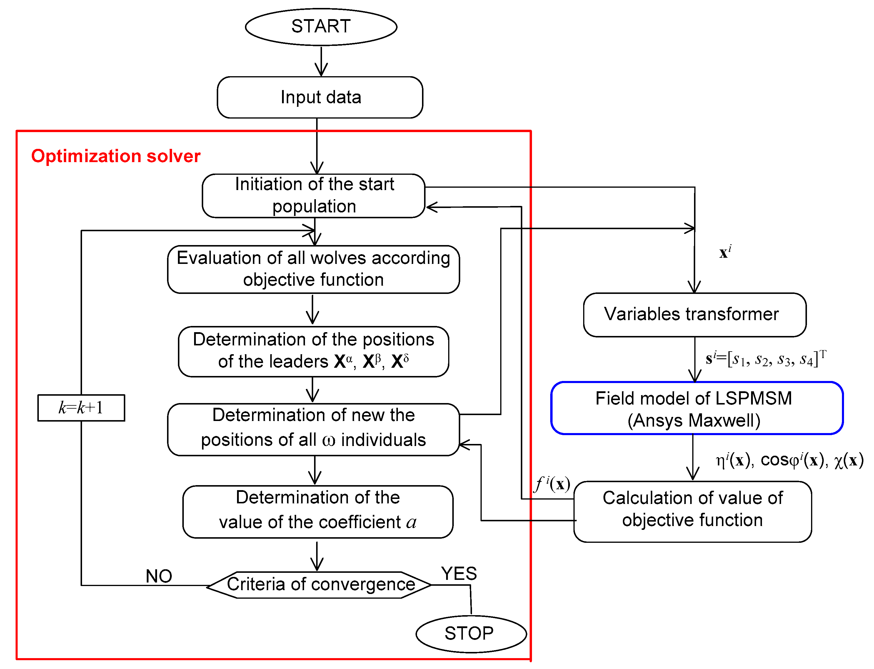
The design process of the low-power line-start PM synchronous motor has been carried out using in-house developed software. The most important part of the in-house software is the optimization solver. The optimization solver has been elaborated in Delphi 7.0 environment. It contains the gray wolf optimization method and is combined with a 2D FEM model of LSPMSM. The optimization solver uses a normalized vector of design variables x. The FEM model of the motor requires the real value of design variables. Therefore, a variable transformer must be used between the optimization solver and the FEM model of LSPMSM. The block diagram of the in-house software is presented in
Figure 4.
The optimization calculations have been performed for wolf pack with 38 individuals. For this number of individuals, a compromise was reached between the accuracy of finding the global extreme and the time of calculation [
6]. As a stop criterion, the maximum number of optimization algorithm iteration
kmax has been assumed. The value of
a parameter is decreased according to Equation (6). The weighting coefficients of optimization procedure have been assumed as:
w1 = 1 and
w2 = 1. The value of the loading torque was equal to the rated torque
TN for the induction motor. The initial positions of all wolves in the initiation procedure were generated randomly. The results of optimization process are presented in
Table 3. The value of η
0 = 73.367% and cosϕ
0 = 0.683. In the successive columns are listed: number of iterations, design variables, phase current, efficiency, power factor and objective function.
Table 3 contains the data for the α individual in the pack.
Based on the results of computer simulation, it can be concluded that the optimization process has been carried out correctly. The values of all functional parameters of the designed motor have significantly improved in the subsequent iterations. The power factor value was improved by about 12%. The efficiency of the motor for the best individual has been improved about by 6% in comparison to the first iteration.
5. Experimental Investigation of LSPMSM Prototype
A three-phase four-pole LSPMSM equipped with the optimized rotor has been manufactured. The stator consists of 24 slots and is equipped with three-phase single-layer overlapping winding.
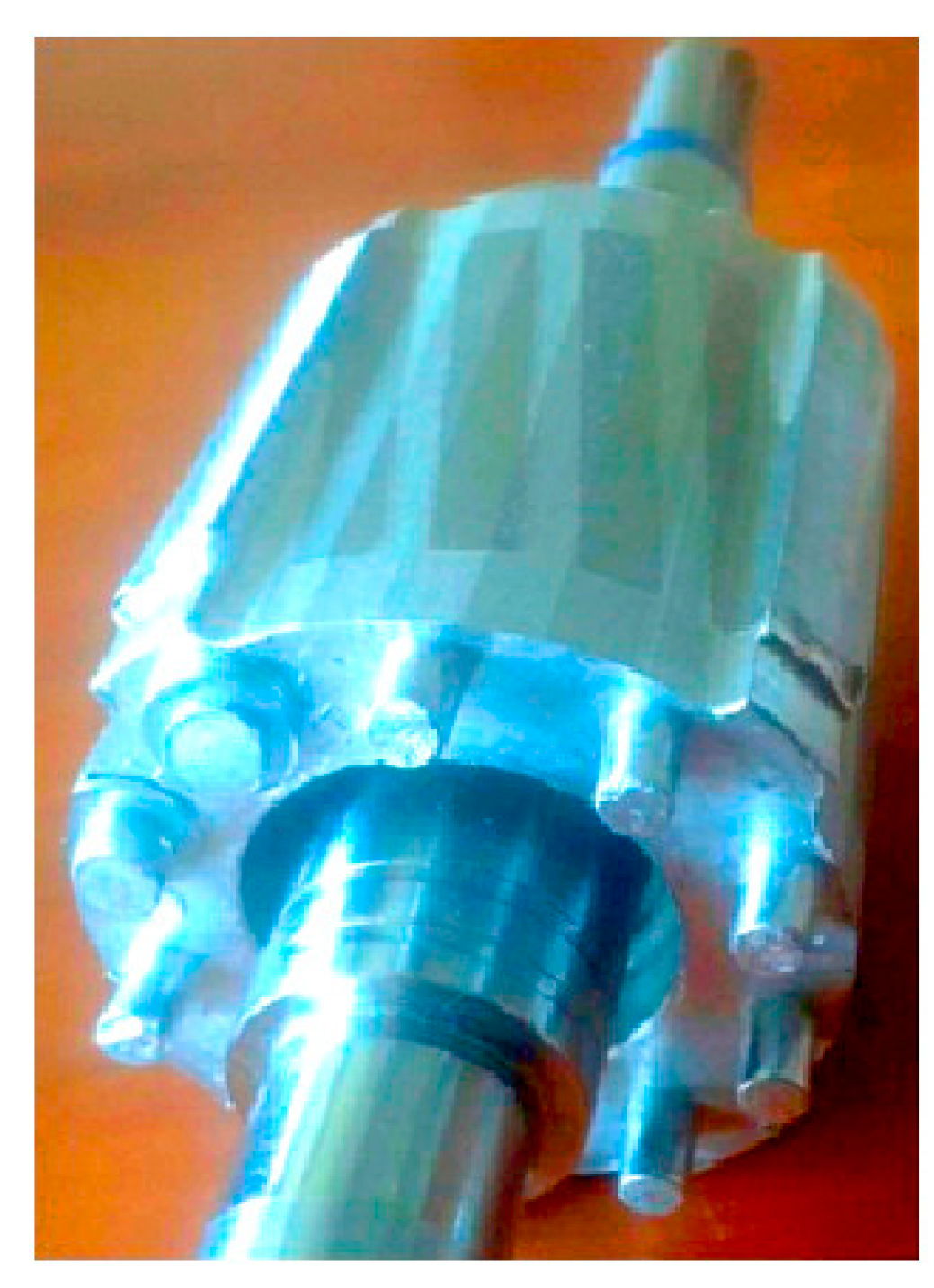
The rotor cage has 18 bars made from aluminum. Four gaps were milled on the surface of the rotor. The rotor with milled gap for mounting magnets is shown in
Figure 5. Four pieces of the permanent magnet were glued into milled gaps.
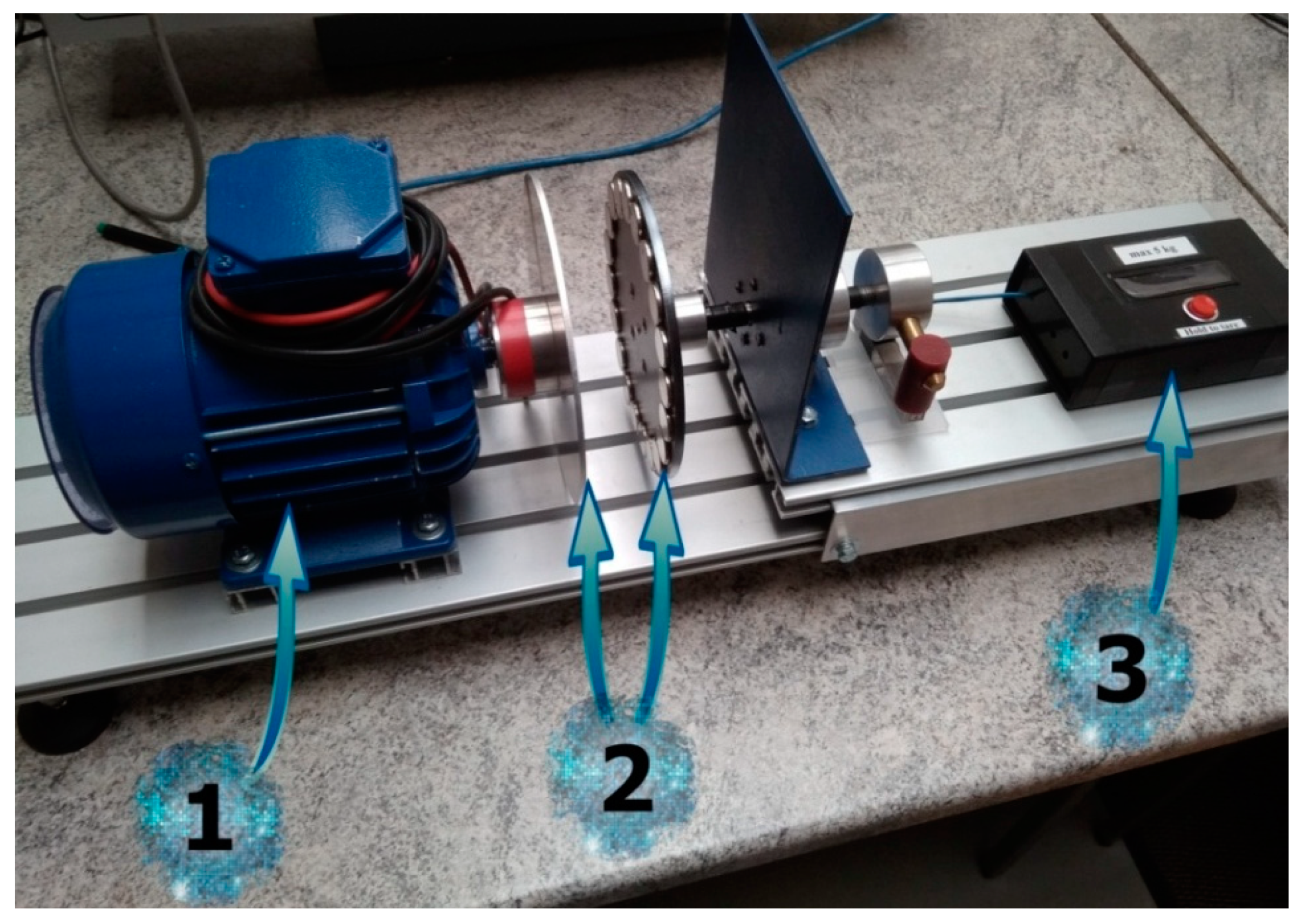
A photo of lab test setup for experimental verification of motor prototype is presented in
Figure 6. The lab setup was adjusted to determine the functional parameters of the prototype. An experimental setup included motor prototype, eddy-current brake, power measurement system and load measurement system. The eddy-current brake consists of two discs made from (a) aluminum with a radius equal to 85 mm and (b) steel with a radius equal to 80 mm. An aluminum disc was mechanically connected with a shaft of LSPMSM. The twenty-disc permanent magnets made of N38 neodymium material were glued to steel disc surface. The load measurement system was built from (a) Arduino Nano, (b) single point mini load cell N27 and (c) SparkFun Load Cell Amplifier type HX711.
Measurements of the prototype were performed in case of supplying by rated value of line voltage equal
VN = 400 V. The influence of the load torque on the motor functional parameters, as a motor efficiency power factor, as well as the phase current, was examined. The results obtained for LSPMSM were compared with the results for the induction motor.
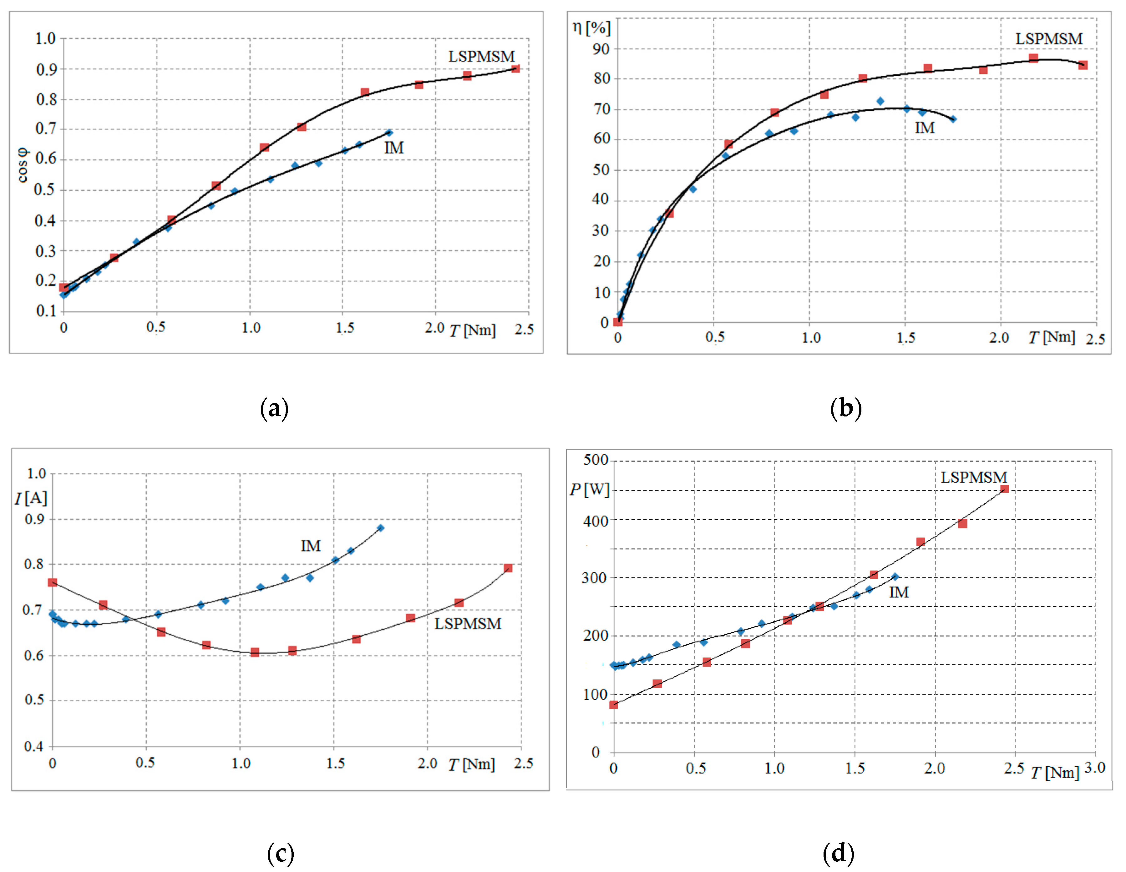
Figure 7 illustrates the comparison of efficiency and power factor and phase current for the designed LSPMSM and induction motor (IM).
It can be observed that, according to experimental results, for the low value of load torque below 0.2
TN, the induction motor has a better cosϕ and η than LSPMSM. The LSPMSM has much better parameters for bigger values of load torque. The application of a hybrid rotor can obtain greater rated power in comparison to IM. The rated power of LSPMSM is equal to 381.5W. In LSPMSM, magnetic flux is produced by the permanent magnets in rotor. Therefore, reactive power drawn from network supply network is compensated. As shown in
Figure 7a, the compensation of reactive power increases the value of the power factor. The LSPMSM has a bigger phase current in comparison to IM in a no-load condition (see
Figure 7c). Increasing the efficiency and power factor in LSPMSM decreases the value of the current drawn from the supply network with the same active power consumption. Changes in the phase current in the function of load torque depends on values of
U/
E, where
U is the phase voltage and
E0 is back-inducted EMF. A detailed analysis of these phenomena is presented in [
27].
Table 4 contains a comparison of the functional parameters in steady-state operation for the primary induction motor and line-start permanent magnet synchronous motor for constant load torque
Tl equal rated torque.
Based on the presented measurement results for both motors, it can be noted that, for the rated value of load torque, a significant improvement in all functional parameters was observed. As a result of the optimization process, the power factor has improved by about 23% in comparison to the induction motor. The efficiency of the LSPMS built using a stator from induction motor has also been significantly improved. Steady-state phase current has reduced by approximately 20% in comparison to the induction motor. During correct start-up, the synchronous motor must attain the synchronous speed [
28,
29]. The start-up process was performed for the supplied voltage in the range of 0.85
VN to
VN. In each of the tested cases, the designed LSPMSM pulls into a synchronism state.
A good correlation between measurements and simulation results was obtained. The difference between the computer simulation results and measurements was about 0.61% for the power factor of the motor. In the case of efficiency, the difference is about 1.53%.
6. Conclusions
In the article, the algorithm and computer software for the designing small-power line-start permanent magnet motors is presented. The gray wolf metaheuristic algorithm was applied in an optimization module. Using elaborated software, the computer-aided design of LSPMSM was performed. A hybrid rotor equipped in cage-winding and permanent magnet instead of the conventional cage rotor from the induction motor was designed. In the rotor, four pieces of the rotor cage were milled. Four pieces of arc-permanent magnet were glued in milled slots.
The optimization process was focused on the improvement in the functional parameters of the motor related to energy efficiency. During the optimization process, the maximized parameters were significantly improved in comparison to the classical squirrel cage induction motor. The prototype was made using optimization results. The efficiency and power factor of the designed motor were determined on the basis of measurements. A significant improvement in the functional parameters in relation to the classical induction motor was attained.
In future research, the optimization solver will be supplemented with other non-deterministic optimization methods, such as particle swarm optimization algorithm and cuckoo search algorithm. Afterwards, the authors plan to perform a comparative calculation for various optimization methods.


