Abstract
Fischer–Tropsch (F–T) fuel, synthesized from coal-to-liquid (CTL), is an alternative fuel with clean and efficient characteristics. In this study, a surrogate fuel model was developed, including n-dodecane (n-C12H26) and iso-octane (i-C8H18), which represents the n-alkane and iso-alkane in F–T fuel synthesized from CTL, respectively. The proportions of the components in the surrogate fuel are determined by the characteristics of the practical fuel, including cetane number (CN), C/H ration and component composition. For the establishment of the skeletal mechanism model, firstly, based on a two-step direct relationship graph (DRG) and the computational singular perturbation (CSP) importance index method, a reduced model of n-dodecane was developed involving 159 species and 399 reactions, while the detailed n-dodecane mechanism consists of 1279 species and 5056 reactions. Then, the n-dodecane skeletal mechanism was constructed based on a decoupling methodology, involving the skeletal C12 mechanism from the reduced mechanism, a C2-C3 sub mechanism and a detailed H2/CO/C1 sub mechanism. Finally, the skeletal mechanism for the F–T surrogate fuel was developed, including the n-dodecane skeletal mechanism and an iso-octane macromolecular skeletal mechanism. The final mechanism for the F–T diesel surrogate fuel consists of 169 species and 406 reactions. The n-dodecane skeletal mechanism and iso-octane skeletal mechanism were validated on various fundamental experiments, including the ignition delay in shock tubes, the primary species concentrations in jet-stirred reactors and the premixed laminar flame over wide operating conditions, which show great agreement between the predictions and measurements. Moreover, an F–T surrogate fuel mechanism was employed to simulate the combustion characteristics of an engine using computational fluid dynamics (CFD). The results show that the mechanism can predict the performance of F–T fuel combustion in engine accurately.
1. Introduction
High efficiency and cleaning combustion are always the goals when developing internal combustion engines (ICEs) [1]. Fischer–Tropsch (F–T) fuel is an alternative fuel derived from coal or natural gas via the Fischer–Tropsch synthesis method. Although it contains thousands of components, the main components are straight-chain saturated hydrocarbons, branched isomeric saturated hydrocarbons and a small number of cycloalkanes. In addition, F–T fuel contains no sulfur and aromatics, generally giving lower emission values when combusted [2]. Compared with petrodiesel, F–T diesel has a higher cetane number (CN) and it can be mixed with petroleum-based diesel directly [3].
Understanding the in-cylinder combustion process is important for clean and efficient utilization for F–T diesel in ICEs. At present, there are few studies on the chemical kinetic model of F–T fuel, especially for CTL. However, the chemical kinetic model of alkane, which is used in the construction of surrogate fuels for traditional gasoline, diesel, jet fuel or other alternative fuels, has been extensively studied. Stephen et al. [4] constructed a synthetic paraffin jet fuel chemical kinetic model containing n-decane (n-C10H22) and iso-octane (iso-C8H18). This model can predict ignition delay in the shock tube and major species concentration of a Jet-Stirred Reactor(JSR) Daguaut et al. [5] investigated a detailed gas-to-liquid (GTL) kinetic model that contains n-heptane, iso-octane and n-propyl cyclohexane. The mechanism consisted of 8217 reactions and 2185 species which could match certain oxidation behaviors. Naik et al. [6] presented detailed chemical kinetic models of Shell GTL and S-8 fuels by analyzing different GTL fuels, and validated the fuel ignition characteristics, laminar flame speed, extinction strain rate and NOx generation characteristics. May-Carle et al. [7] studied the oxidation characteristics of F–T, F–T/biodiesel blends in jet reactors, and constructed a detailed mechanism including n-decane, iso-octane, methyl octoate and ethanol. The detailed mechanism consists 9919 reactions and 2022 species.
Due to the limitation of computational resources, it is very difficult to simulate its combustion process with detailed chemical mechanisms directly using CFD. For practical applications, a skeletal surrogate fuel model with several representative hydrocarbons is often selected to match certain oxidation behaviors for practical fuel [8]. For the CFD simulations of F–T fuel in ICEs, a reliable chemical kinetic skeletal mechanism is needed. However, the previous research mainly focuses on the application of F–T fuel in engines, such as combustion, emission and practical performance. The chemical kinetics of F–T fuel have not been deeply studied. In this study, a skeletal surrogate fuel mechanism was established for F–T fuel. First, the detailed n-dodecane mechanism was reduced based on the directed relation graph and CSP method. Second, an n-dodecane skeletal mechanism is constructed using decoupling methodology. Then, the F–T fuel surrogate skeletal mechanism is constructed, including an n-dodecane skeletal mechanism and an iso-octane macromolecular mechanism. Finally, the mechanism is validated based on various fundamental experiments and a practical engine.
2. Model Development Theory
2.1. F–T Fuel Surrogate Model
The proportion of the components in the surrogate fuel is determined by the chemical characteristics of F–T fuel [9]. Based on the properties of the F–T fuels synthesized from CTL, as shown in Table 1, a reasonable surrogate of the fuel is constructed, consisting of 76% n-dodecane and 24% iso-octane. The surrogate fuel emulates the gas phase combustion kinetic phenomena exhibited by real fuels, on a specific basis through the sharing of its C/H molar ratio (C/H) and cetane number (CN) [10].

Table 1.
Compositions and properties of Fischer–Tropsch (F–T) and surrogate fuel.
Dooley et al. [11] presented that the activation of mixture fuel is mainly affected by n-alkanes. Therefore, the key to constructing the fuel chemical kinetic model of F–T fuel is to construct the n-dodecane skeletal mechanism accurately. Westbrook et al., of Laurence Livermore National Laboratory (LLNL) [12], constructed a detailed kinetic mechanism of n-dodecane, which is validated to be able to reproduce the combustion characteristics of n-dodecane.
In this study, the n-dodecane model is established based on LLNL’s detailed model [12] because it involves the oxidation process of heavy alkanes from low temperatures to high temperatures. Moreover, as an important component of gasoline fuel, iso-octane has been widely studied as a surrogate fuel for gasoline and aviation kerosene, and so on. In this study, the i-C8H18 sub-mechanism is constructed based on the skeletal mechanism constructed by Liu et al. [13,14].
2.2. Direct Relationship Graph (DRG) Method
Due to the considerable species and reactions in the detailed mechanism, the relationship between the different components is too complex to reduce. The direct relation graph (DRG) is used to describe the coupling relationship between each component, which provides a good solution for eliminating the unimportant components and dealing with the relationships between components. In DRG, if the change in component B will cause great errors in component A, component B is more important than component A, as shown below:
where is the reaction rate of the i-th elementary reaction in the mechanism, is the stoichiometric coefficient of component A in the i-th elemental reaction, I is the total number of elementary reactions in the mechanism. is the contribution rate of component B to A. When is sufficiently large, removal of component B will result in a large error in A. In the DRG method, select the initial important component and set a threshold to remove unimportant components or reactions in the mechanism. In the process of reducing the detailed mechanism, will change with the decrease in compositions. is defined as below:
In DRG method, there are two steps to reduce a mechanism. Firstly, set the important components and the threshold. Secondly, calculate of the important components by Equation (3), then remove the reaction which is less than the threshold, otherwise retain it.
2.3. Computational Singular Perturbation (CSP) Importance Index Method Method
In computational singular perturbation (CSP), quasi-steady state components are substances with small chemical reaction time scales. The CSP method divides the reaction space into fast and slow sub-spaces, and couples them to further reduce the computational rigidity. The most important thing is selecting the quasi-steady state components and solving their concentrations in this method, which is defined as follows:
where is concentration of the a-th component. is the number of species, is the number of elements; the rate of change can be expressed as:
where is the Jacobian matrix. By applying the similarity transformation to the matrix: , and are base vectors, , then decouple the fast and slow modes through the following two steps:
Ignore , in Formula (6), the matrix has an effect on the speed of the mode response. Decoupling it:
Based on the above theory, a method is proposed to identify quasi-steady state species:
where is the threshold and identifies species that contribute less to the slow mode as quasi-steady components.
2.4. Decoupling Method
Over the past 30 years, several researchers have found that different species play different roles in the oxidation process in the mechanism. Ranzi et al. [15] found that small molecule reactions are critical to the laminar flame speeds. Ji et al. [16] also investigated the chemical reaction characteristics of small molecules and their free radicals and found that they are more sensitive to the extinction strain rate. Hu and Keck [17] and Cox and Cole [18] have studied the ignition delay of heavy alkanes and found that it can be well predicted by the macromolecular skeletal reaction mechanism.
According to the above studies, it is concluded that the detailed oxidation process of small molecules is more sensitive to the flame characteristics, while the species concentrations and the ignition delay are mainly determined by the oxidation process of large molecules.
Therefore, some researchers have proposed the decoupling method to construct a skeletal mechanism [19]. In this method, the mechanism is divided into three parts: the skeletal sub-mechanism is used to predict species histories and ignition characteristics; the detailed C1/CO/H2 sub-mechanism is used to predict the heat release rate, flame propagation and the concentration of corresponding components in the fuel; as a transition mechanism, a reduced C2-C3 sub-mechanism is used to combine the other two sub-mechanisms [19] because it has an assignable influence on species concentration, as found in some recent research [20]. The skeletal model based on this method can predict the oxidation behavior accurately, while the skeletal mechanism can control it on a small scale [13,19].
3. Model Formulation
3.1. Simplified Mechanism of n-Dodecane
The reduced n-dodecane model was simplified from LLNL [12] by DRG and CSP methods. In the DRG method, the equivalent ratios () were 0.5 and 1.0, the initial temperatures were 1000, 1100, 1200, 1400 and 1600 K, and pressures () were 1.0×10⁵ and 1.0×10⁶ Pa. N-C12H26, CO2, H2O, N2 and O2 were selected as important components. It can be seen from Figure 1 that with the threshold value increased, the number of species of the reduced mechanism decreased, while the average error increased gradually. It was especially noticeable that the average error rose sharply when the threshold was more than 0.20. In practical applications, the error is generally controlled below 30%.
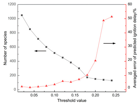
Figure 1.
The results of species number and averaged error under different threshold value.
Through the first DRG simplification, the threshold of the first step was selected as 0.18, and the number of species and reactions of the reduced mechanism were 174 and 660.
In order to further reduce the mechanism and control the error to a small extent, Lu et al. [21] proposed a multi-step direct relation graph method, which is simplified on the basis of the first step.
Figure 2 shows the comparison of ignition delay obtained by the one-step DRG method, two-step DRG method and detailed mechanism. Compared to the one-step DRG method, the simplified mechanism obtained by the two-step DRG method has fewer components and reactions, and the error is smaller, which is more suitable for CFD simulation.
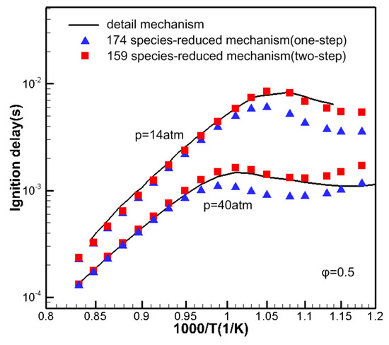
Figure 2.
The ignition delay time of n-dodecane with detailed mechanism and reduced mechanisms by one-step and two-step direct relationship graph (DRG) method.
In this paper, the n-dodecane of detailed mechanism was reduced by the two-step DRG method with threshold values of 0.18 and 0.23. The reduced mechanism includes 159 species and 584 reactions. To further simplify the number of reactions in the mechanism, the CSP method is used. For the CSP method, all the components in the reduced mechanism are set as important components and the threshold of the reaction is set as 0.01, and the redundant 185 reactions are removed. The final simplified n-dodecane mechanism contained 159 species and 399 reactions.
3.2. Skeletal Mechanism of n-Dodecane
Based on the reaction rate and reaction path, a C12 sub-mechanism was built from simplified mechanism. Figure 3 shows the rate of production of detailed n-dodecane mechanism at 600, 800, and 1000K in a perfectly stirred reactor (PSR). Whether at a low or high temperature, the dehydrogenation reaction of the C12H26 and OH radicals dominates the consumption of C12H26. As the temperature increases, the free radicals H and HO2 begin to participate in the reactions, but the consumption of C12H26 is still mainly affected by OH radicals.
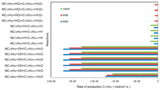
Figure 3.
Rate of production C12H26 in a perfectly stirred reactor (PSR) at P = 0.1 MPa, = 0.5.
The n-dodecane skeletal mechanism consists of three parts: the oxidation mechanism of the C12 macromolecular component from the simplified mechanism, the C2-C3 transition mechanism from the Westbrook et al. [12] model and the detailed H2/CO/C1 sub-mechanism from Klippenstein et al. [22]. The main reaction pathway is shown in Figure 4.
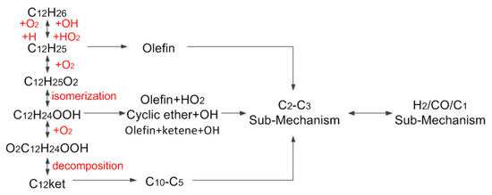
Figure 4.
Main reactions pathway of n-dodecane oxidation.
At low temperatures, C12H26 oxidizes to C12H25 and HO2. C12H25 reacts with O2 to form C12H25O2, and the reaction will be reversed as the temperature increases. With the increase in C12H25, C12H25 reacts with O2 to form C12H24 and HO2, and C12H24 is further decomposed into smaller species. The isomerization of C12H25O2 produces C12H24OOH, and C12H24OOH reacts with O2 to form O2C12H24OOH. This component is unstable. It is easy to release the OH radical and it is then further isomerized to form C12ket. The C12ket is then decomposed to form small molecule free radicals of different compositions.
3.3. Skeletal Mechanism of Surrogate Fuel
In this paper, the F–T fuel skeletal mechanism was constructed using a decoupling methodology. The mechanism of C4-Cn was based on the detailed mechanism constructed by Westbrook et al. [12], the i-C8H18 sub-mechanism was constructed based on the skeletal mechanism constructed by Liu et al [13,14], the detailed sub-mechanism of H2/CO/C1 is from Klippenstein et al. [22] and the reduced C2-C3 sub-mechanism comes from the Westbrook et al. [12] model. As a skeletal mechanism for surrogating fuels, it is necessary to be able to predict the ignition delay, heat release rate, species histories and flame propagation speed under a wide range of operating conditions, and to make the number of species of the mechanism as simple as possible. Using the decoupling method to construct the skeletal oxidation mechanism of surrogate fuel of F–T fuel can achieve this goal. The main reaction path is shown in Figure 5. As can be seen, the F–T fuel skeletal mechanism was constructed by integrating the skeletal C12 and C8 sub-mechanism with a C2–C3 reduced mechanism and a detailed H2/CO/C1 oxidation mechanism.
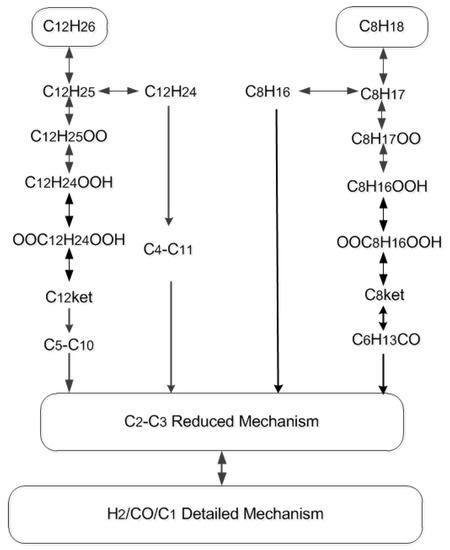
Figure 5.
Main reaction path of F–T fuel surrogate model skeletal mechanism.
4. Model Validation
The fundamental experimental data obtained in shock tubesand jet stirred reactors and premixed laminar flamesare essential for assessing and validating the performance of surrogate fuel. Chemkin-Pro was used for the simulations in this section.
4.1. Validation of Ignition Delay of Shock Tube
The shock tube is mainly used to validate the fuel ignition characteristics. The closed homogeneous batch reactor in Chemkin-Pro was used to solve the calculation under homogeneous constant volume and adiabatic conditions. We set the simulation conditions based on the experimental pressure and temperature in the literature [23,24,25].
In order to validate the accuracy of the ignition delay of the skeletal mechanism, the measurements of Vasu [23] were compared with the simulations of an n-dodecane skeletal mechanism and a detailed mechanism from Westbrook [12] (of LLNL) at various pressures () and temperatures () for equivalence ratios () of 0.5 and 1.0, respectively. At = 20 atm, the simulation results of the n-dodecane skeletal mechanism with an ignition delay that had different equivalence ratios are shown in Figure 6a. It can be seen from Figure 6a, the ignition delay decreases with increasing temperature. At = 0.5, the skeletal mechanism, detailed mechanism and experimental data show the same trend of change and are relatively consistent. At = 1.0, the skeletal mechanism and detailed mechanism are slightly higher than the measurements. The overall uncertainty of Vasu’s [23] measurements in was ± 10%, dominated by uncertainties in the determination of the reflected shock temperature (±1%). At low temperatures, the simulations of the current mechanism are slightly lower than those of the detailed mechanism. As is shown in Figure 6b, at = 10 atm, 50atm, the simulations of iso-octane are compared with the measurements of Shen [24] and Davidson [25]. When = 0.5, the simulations are in good agreement with the measurements. When = 1.0, the simulations are slightly higher than those at a low temperature.
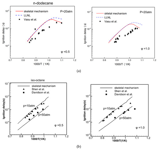
Figure 6.
Comparison of simulation (line) and measured (symbol) [23,24,25] ignition delay in shock tubes with (a) n-dodecane and (b) iso-octane.
Figure 7 illustrates the sensitivity analysis for n-dodecane and iso-octane at = 2.0 MPa, = 1.0 and = 800 K in the NTC regime and at = 1200 K in the high-temperature regime. The sensitivity coefficients (SC) are defined as the resulting percentage change in the ignition delay time () by doubling the rate constant of the ith reaction,
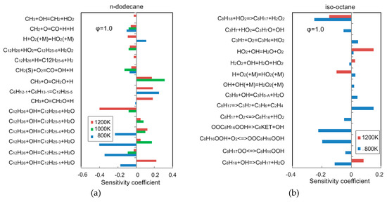
Figure 7.
Sensitivity coefficient of ignition delay time at = 2.0 MPa and = 1.0 with (a) n-dodecane; (b) iso-octane.
Reactions with positive SC decelerate ignition and make ignition delay longer, and those with negative SC accelerate ignition and result in shorter ignition delay. It can be observed that fuel-related reactions show high sensitivity coefficients. At 800 K, the ignition delay time is mainly determined on low-temperature reactions for the two components. At 1200 K, the reactions involving CH3, OH and HO2 perform high sensitivity coefficient.
The sensitivity analysis is performed using detailed mechanism to identify important low temperature reactions for ignition delay at P = 2.0 MPa, = 1.0 and T = 800 K, 1000 K. As shown in Figure 8, the reaction of C12H26+OH=C12H25+H2O has the largest sensitivity coefficient at low temperatures. In future studies, this situation can be improved by correcting the rate constant of the reaction based on the effective and sufficient experimental data.
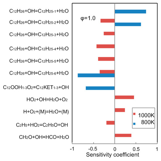
Figure 8.
Sensitivity coefficient of ignition delay time at = 2.0 MPa and = 1.0, calculated using detailed mechanism from Laurence Livermore National Laboratory (LLNL) [12].
Although there are uncertainties in the experiment and some deviations at low temperatures, the prediction of the ignition delay time by this model is satisfactory. However, most of the current experimental data are concentrated on high-temperature conditions. In future investigations, it will be necessary to optimize the characterization of fuel composition and the content of each component based on more low temperature experimental data.
4.2. Validation of Primary Species Concentration of JSR
Pitz and Mueller [26] revealed that the species histories are extremely important in the validation of a chemical kinetic mechanism for surrogate fuels. Thus, the evolutions of major species concentrations of C12H26, O2, H2O, CO, CO2 and C2H2 are validated by comparing them with the JSR measurements of Ahmed et al. [27] from 550 to 1100K at 10atm, with different equivalence ratios of 0.5 and 1.0. It can be seen from Figure 9 that the current reduced mechanism can better predict the concentration changes of the major components in the jet-stirred reactor, but slightly underestimates the concentration of H2O and CO. At = 0.5, from 650 to 800K, the concentration of C12H26 is overestimated. Meanwhile, the concentration of C2H2 is overestimated from 750 to 1000K, but the overall predictions are still reasonable. Westbrook et al. [12], Mze-Ahmed et al. [27] and Mehl et al. [28] also found that the predicted value of CO2 concentration was low at low temperatures when using a detailed mechanism to predict the oxidation behavior of hydrocarbon fuels.
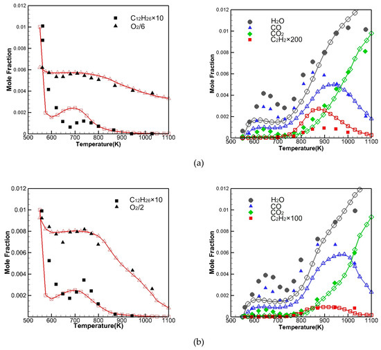
Figure 9.
Comparison of simulation (lines with hollow symbols) and measured [27] (solid symbols) major species concentration at (a) = 0.5 and (b) = 1.0 in JSR.
Mehl et al. [28] stated that the low prediction value of CO2 concentration may be due to the lack of the description of partial oxidation products in the mechanism, with the same problem existing in the present mechanism.
4.3. Validation of Laminar Flame Speeds
The laminar flame propagation velocity is one of the important parameters that is indicative of fuel combustion characteristics; it is solved by the premixed laminar flame-speed calculation reactor in Chemkin-Pro. The parameters are set according to the experimental pressure and inlet conditions. The present mechanism is validated in this section by comparing it with the measured [16,29,30] laminar flame speeds for the n-dodecane and iso-octane. As shown in Figure 10a, at = 1 atm and the unburned gas temperatures () 403 and 470 K, the laminar flame speed of n-dodecane varies with the equivalence ratio from 0.7 to 1.4. As shown in Figure 10a, in the range of equivalence ratio from 1.0 to 1.4, we can see that simulations are slightly higher than experimental values. Figure 10b shows that the laminar flame speed of iso-octane varies with the equivalence ratio and pressure from 1 to 3 atm at = 400 K. The iso-octane skeletal mechanisms are in good agreement with the experimental values of Hui and Sung [30]. With the increase in equivalence ratio, the laminar flame speed of n-dodecane and iso-octane increases and then decreases, and the maximum value is around the equivalence ratio of 1.1. However, when the equivalence ratios are relatively large, the simulations are slightly higher than the measurements.
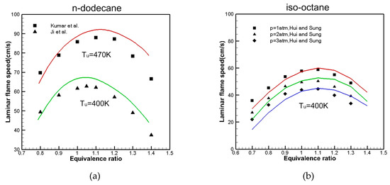
Figure 10.
Comparison of the calculated (line) and measured (symbol) [16,29,30] of laminar flame speed with (a) n-dodecane and (b) iso-octane.
Figure 11 shows the sensitivity coefficients of laminar flame speed at = 400 K, = 0.1 MPa and = 0.7, 1.1, 1.4. It can be observed that the C0-C3 reactions are more sensitive than other reactions to the flame propagation velocity of n-dodecane and iso-octane, so accurate C1/CO/H2 sub-mechanisms are essential for the prediction of flame propagation speed. Therefore, the current mechanism still needs to be further improved; because CH3 can inhibit the flame propagation speed, the high concentration of CH3 will reduce the flame propagation speed [15,31] and the increased concentration of H atoms will increase the flame propagation.
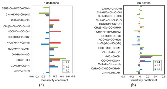
Figure 11.
Sensitivity coefficients of laminar flame speed at T = 400 K and P = 0.1 MPa with (a) n-dodecane and (b) iso-octane
The reaction rates of three reactions, H+O2=O+OH, HCO+M=H+CO+M, CH3+H(+M)=CH4(+M), should be adjusted to reproduce the laminar flame speed. Overall, the agreement between the predictions and the measurements provides confidence in the present mechanism reagrding its prediction of the laminar flame speed for practical F–T fuels.
4.4. Validation Mechanism in an Engine
In order to further validate the accuracy of the skeletal mechanism of the F–T surrogate fuel, it is necessary to test in the engine. The main engine specifications are show in Table 2. A schematic diagram of the test engine is shown in Figure 12. The engine used in the test was made by Quanchai (Anhui, China), the engine operation was controlled using a measurement and control system made by Sichuan Chengbang (Chengdu, China). The in-cylinder combustion pressure was measured by a Kistler 6052c pressure sensor. The crankshaft position was determined by the Hall sensor of a Hyundai Mobis (Model 39180, Korea), the crank angle and top dead center signals were obtained by pulse signal. Signals were acquired and recorded using the YE6232B 16-channel data acquisition instrument from Sinocera Piezotronics. The sampling frequency of the instrument was 96 kHz, and the sampling time of each working condition was 30 s. The engine was operated at the speed of 1600r/min with a load of 10 and 50Nm. Both the accuracy and uncertainty of the measuring equipment are shown in Table 3.

Table 2.
Main engine specifications.
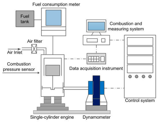
Figure 12.
Schematic diagram of engine test bench.

Table 3.
Accuracy and uncertainty of the measuring equipment.
In order to analyze the combustion characteristics of F–T diesel in the cylinder, the F–T fuel surrogate model skeletal mechanism constructed in this work was used in numerical simulation. According to the parameters of QCH1125 engine, a combustion chamber model was established. The CFD software CONVERGE was used to simulate the combustion process. The CONVERGE software has an automatic meshing function, which improves the calculation speed while ensuring the calculation accuracy. As shown in Figure 13, the scheme is as follows: the basic grid size is 4 mm, the temperature and speed gradients are automatically encrypted three times, the combustion chamber area is encrypted 2 mm, the nozzle area is 1 mm, and the spray area is 2 mm. The turbulence model is re-normalization group (RNG) model, the spray breakup model is a Kelvin–Helmholtz/Rayleigh–Taylor (KH–RT) model and the combustion model is a SAGE model.
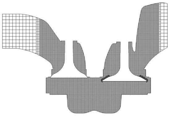
Figure 13.
Schematic diagram of engine test bench.
The CFD software is used to simulate the working process of a diesel engine fueled with F–T fuel, the calculation results shown in Figure 14 are in good agreement with the measurements, indicating that the skeletal mechanism can predict the performance of F–T fuel in cylinder combustion.
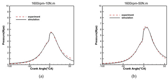
Figure 14.
Comparison of simulation and experimental combustion pressure with a load of (a) 1600rpm-10N.m and (b) 1600rpm-50N.m.
5. Conclusions
In our analysis of the components of F–T fuel, the surrogate model is built with 76% n-dodecane and 24% iso-octane, respectively. It could reproduce the H/C molar ratio (H/C), cetane number (CN) and average molecular weight of the target fuel. If we compare the two-step DRG method with the one-step DRG method, the two-step DRG method makes the number of components in the mechanism more simplified with less errors.
Firstly, based on the two-step DRG method and the CSP method, the detailed n-dodecane mechanism, which consists of 1279 species and 5056 reactions, is reduced to 159 species and 399 reactions. Then, by employing a decoupling methodology, the n-dodecane skeletal mechanism is constructed, which combines the C2-C3 sub-mechanism and the detailed H2/CO/C1 sub-mechanism. Finally, an iso-octane macromolecular oxidation mechanism is coupled with an n-dodecane skeletal mechanism to form an F–T fuel surrogate model skeletal mechanism. This model consists of 169 species and 406 reactions.
The results show that the macromolecule skeletal mechanism could emulate the ignition delay time, species concentration and laminar flame speed of n-dodecane and iso-octane in the combustion process under a wide range of operating conditions. Finally, the combustion process of F–T fuel is numerically calculated based on the multi-dimensional model of the engine. The calculation results show that the F–T fuel surrogate model skeletal mechanism can predict the working characteristics of F–T fuel in an engine.
In conclusion, the present two-component F–T fuel combustion model gives a reliable performance for combustion predictions, as well as computational efficiency improvements, through the use of a reduced mechanism for multi-dimensional CFD simulations. The results of this research have great significance for deeply exploring the combustion mechanism of F–T diesel in the cylinder and the clean utilization of F–T fuel.
Author Contributions
The contributions of the individual authors to this research work are as follows: R.Z. and Y.F. provided valuable suggestions for improving the model and test design, R.L. and T.Y. performed the experiments, Y.F. reviewed and edited the manuscript, R.L. analyzed the simulation results and wrote the paper. All authors have read and agreed to the published version of the manuscript.
Conflicts of Interest
The authors declare no conflict of interest.
References
- Shahib-Eldin, A. New Energy Technologies: Trends in the Development of Clean and Efficient Energy Technologies. Opec Rev. 2010, 26, 261–307. [Google Scholar] [CrossRef]
- Shi, J.; Wang, T.; Zhao, Z.; Yang, T.; Zhang, Z. Experimental Study of Injection Parameters on the Performance of a Diesel Engine with Fischer–Tropsch Fuel Synthesized from Coal. Energies 2018, 11, 3280. [Google Scholar] [CrossRef]
- Balagurunathan, J.; Flora, G.; Saxena, S.; Kahandawala, M.; Dewitt, M.; Sidhu, S.; Corporan, E. Ignition Delay Times of a Range of Alternate Jet-Fuels and Surrogate Fuel Candidate Hydrocarbons under Fuel-Lean Conditions: A Shock Tube Study. In Proceedings of the Aiaa Aerospace Sciences Meeting Including the New Horizons Forum & Aerospace Exposition, Orlando, FL, USA, 4–7 January 2011. [Google Scholar]
- Dooley, S.; Sang, H.W.; Jahangirian, S.; Ju, Y.; Dryer, F.L.; Wang, H.; Oehlschlaeger, M.A. The combustion kinetics of a synthetic paraffinic jet aviation fuel and a fundamentally formulated, experimentally validated surrogate fuel. Combust. Flame 2012, 159, 3014–3020. [Google Scholar] [CrossRef]
- Dagaut, P.; Karsenty, F.; Dayma, G.; Diévart, P.; Hadj-Ali, K.; Mzé-Ahmed, A.; Braun-Unkhoff, M.; Herzler, J.; Kathrotia, T.; Kick, T. Experimental and detailed kinetic model for the oxidation of a Gas to Liquid (GtL) jet fuel. Combust. Flame 2014, 161, 835–847. [Google Scholar] [CrossRef]
- Naik, C.V.; Puduppakkam, K.V.; Modak, A.; Meeks, E.; Wang, Y.L.; Feng, Q.; Tsotsis, T.T. Detailed chemical kinetic mechanism for surrogates of alternative jet fuels. Combus. Flame 2011, 158, 434–445. [Google Scholar] [CrossRef]
- May-Carle, J.B.; Pidol, L.; Nicolle, A.; Anderlohr, J.M.; Togbé, C.; Dagaut, P. Experimental and Numerical Study of F-T/Biodiesel/Bioethanol Surrogate Fuel Oxidation in Jet-Stirred Reactor. Combust. Sci. Technol. 2012, 184, 901–915. [Google Scholar] [CrossRef]
- Huang, Y.C.; Zhou, L.B.; Jiang, D.M. Study and Development of Fischer-Tropsch(F-T) Diesel Fuel as a Clean Alternative Fuel for Diesel Engines. Chin. Int. Combust. Engine Eng. 2005, 26, 18–23. [Google Scholar]
- Sang, H.W.; Haas, F.M.; Dooley, S.; Edwards, T.; Dryer, F.L. Reconstruction of chemical structure of real fuel by surrogate formulation based upon combustion property targets. Combust. Flame 2017, 183, 39–49. [Google Scholar]
- Dooley, S.; Sang, H.W.; Heyne, J.; Farouk, T.I.; Ju, Y.; Dryer, F.L.; Kumar, K.; Xin, H.; Sung, C.J.; Wang, H. The experimental evaluation of a methodology for surrogate fuel formulation to emulate gas phase combustion kinetic phenomena. Combust. Flame 2012, 159, 1444–1466. [Google Scholar] [CrossRef]
- Dooley, S.; Won, S.H.; Chaos, M.; Heyne, J.; Ju, Y.; Dryer, F.L.; Kumar, K.; Sung, C.-J.; Wang, H.; Oehlschlaeger, M.A.; et al. A jet fuel surrogate formulated by real fuel properties. Combust. Flame 2010, 157, 2333–2339. [Google Scholar] [CrossRef]
- Westbrook, C.K.; Pitz, W.J.; Herbinet, O.; Curran, H.J.; Silke, E.J. A comprehensive detailed chemical kinetic reaction mechanism for combustion of n-alkane hydrocarbons from n-octane to n-hexadecane. Combust. Flame 2009, 156, 181–199. [Google Scholar] [CrossRef]
- Liu, Y.; Ming, J.; Xie, M.; Pang, B. Improvement on a skeletal chemical kinetic model of iso-octane for internal combustion engine by using a practical methodology. Fuel 2013, 103, 884–891. [Google Scholar] [CrossRef]
- Liu, Y.D.; Jia, M.; Xie, M.Z.; Pang, B. Enhancement on a Skeletal Kinetic Model for Primary Reference Fuel Oxidation by Using a Semidecoupling Methodology. Energy Fuels 2012, 26, 7069–7083. [Google Scholar] [CrossRef]
- Ranzi, E.; Frassoldati, A.; Grana, R.; Cuoci, A.; Faravelli, T.; Kelley, A.P.; Law, C.K. Hierarchical and comparative kinetic modeling of laminar flame speeds of hydrocarbon and oxygenated fuels. Prog. Energy Combust. Sci. 2012, 38, 468–501. [Google Scholar] [CrossRef]
- Ji, C.; Dames, E.; Wang, Y.L.; Hai, W.; Egolfopoulos, F.N. Propagation and extinction of premixed C 5 –C 12 n -alkane flames. Combust. Flame 2010, 157, 277–287. [Google Scholar] [CrossRef]
- Hu, H.; Keck, J. Autoignition of Adiabatically Compressed Combustible Gas Mixtures. SAE Trans. 1987, 96, 592–604. [Google Scholar]
- Cox, R.A.; Cole, J.A. Chemical aspects of the autoignition of hydrocarbon air mixtures. Combust. Flame 1985, 60, 109–123. [Google Scholar] [CrossRef]
- Chang, Y.; Ming, J.; Li, Y.; Liu, Y.; Xie, M.; Hu, W.; Reitz, R.D. Development of a skeletal mechanism for diesel surrogate fuel by using a decoupling methodology. Combust. Flame 2015, 162, 3785–3802. [Google Scholar] [CrossRef]
- Chang, Y.; Jia, M.; Niu, B.; Xu, Z.; Liu, Z.; Li, Y.; Xie, M. Construction of a skeletal oxidation mechanism of n-pentanol by integrating decoupling methodology, genetic algorithm, and uncertainty quantification. Combust. Flame 2018, 194, 15–27. [Google Scholar] [CrossRef]
- Lu, T.; Law, C.K. Linear time reduction of large kinetic mechanisms with directed relation graph: N-Heptane and iso-octane. Combust. Flame 2006, 144, 24–36. [Google Scholar] [CrossRef]
- Klippenstein, S.J.; Harding, L.B.; Davis, M.J.; Tomlin, A.S.; Skodje, R.T. Uncertainty driven theoretical kinetics studies for CH3OH ignition: HO2 + CH3OH and O2 + CH3OH. Proc. Combust. Inst. 2011, 33, 351–357. [Google Scholar] [CrossRef]
- Vasu, S.S.; Davidson, D.F.; Hong, Z.; Vasudevan, V.; Hanson, R.K. n-Dodecane oxidation at high-pressures: Measurements of ignition delay times and OH concentration time-histories. Proc. Combust. Inst. 2009, 32, 173–180. [Google Scholar] [CrossRef]
- Shen, H.-P.S.; Vanderover, J.; Oehlschlaeger, M.A. A shock tube study of iso-octane ignition at elevated pressures: The influence of diluent gases. Combust. Flame 2008, 155, 739–755. [Google Scholar] [CrossRef]
- Davidson, D.F.; Gauthier, B.M.; Hanson, R.K. Shock tube ignition measurements of iso-octane/air and toluene/air at high pressures. Proc. Combust. Inst. 2005, 30, 1175–1182. [Google Scholar] [CrossRef]
- Pitz, W.J.; Mueller, C.J. Recent progress in the development of diesel surrogate fuels. Prog. Energy Combust. Sci. 2011, 37, 330–350. [Google Scholar] [CrossRef]
- Mzé-Ahmed, A.; Hadj-Ali, K.; Dagaut, P.; Dayma, G. Experimental and Modeling Study of the Oxidation Kinetics of n-Undecane and n-Dodecane in a Jet-Stirred Reactor. Energy Fuels 2012, 26, 4253–4268. [Google Scholar] [CrossRef]
- Mehl, M.; Pitz, W.J.; Sarathy, S.M.; Westbrook, C.K. Modeling the combustion of high molecular weight fuels by a functional group approach. Int. J. Chem. Kinet. 2012, 44, 257–276. [Google Scholar] [CrossRef]
- Kumar, K.; Sung, C.J. Laminar flame speeds and extinction limits of preheated n -decane/O2/N2 and n -dodecane/O2/N2 mixtures. Combust. Flame 2007, 151, 209–224. [Google Scholar] [CrossRef]
- Hui, X.; Sung, C.-J. Laminar flame speeds of transportation-relevant hydrocarbons and jet fuels at elevated temperatures and pressures. Fuel 2013, 109, 191–200. [Google Scholar] [CrossRef]
- Ji, C.; Sarathy, S.M.; Veloo, P.S.; Westbrook, C.K.; Egolfopoulos, F.N. Effects of fuel branching on the propagation of octane isomers flames. Combust. Flame 2012, 159, 1426–1436. [Google Scholar] [CrossRef]
© 2020 by the authors. Licensee MDPI, Basel, Switzerland. This article is an open access article distributed under the terms and conditions of the Creative Commons Attribution (CC BY) license (http://creativecommons.org/licenses/by/4.0/).