Abstract
A mono tiltrotor (MTR) design which combines concepts of a tiltrotor and coaxial rotor is presented. The aerodynamic modeling of the MTR based on blade element momentum theory (BEMT) is conducted, and the method is fully validated with previous experimental data. An automated optimization approach integrating BEMT modeling and optimization algorithms is developed. Parameters such as inter-rotor spacing, blade twist, taper ratio and aspect ratio are chosen as design variables. Single-objective (in hovering or in cruising state) optimizations and multi-objective (both in hovering and cruising states) optimizations are studied at preset design points; i.e., hovering trim and cruising trim. Two single-objective optimizations result in different sets of parameter selections according to the different design objectives. The multi-objective optimization is applied to obtain an identical and compromised selection of design parameters. An optimal point is chosen from the Pareto front of the multi-objective optimization. The optimized design has a better performance in terms of the figure of merit (FM) and propulsive efficiency, which are improved by 7.3% for FM and 13.4% for propulsive efficiency from the prototype, respectively. Further aerodynamic analysis confirmed that the optimized rotor has a much more uniform load distribution along the blade span, and therefore a better aerodynamic performance in both hovering and cruising states is achieved.
1. Introduction
The speed limit of a conventional helicopter is normally below 350 km/h [1] due to its inherent aerodynamic characteristics; e.g., the tip stall of the retreating blade and compressibility effects of the advancing blade. New concepts of rotorcraft design compounded with fixed wings have been put forward to break this speed limit. These conceptual rotorcrafts combine both the capabilities of conventional helicopters, such as vertical takeoff and hovering, and fixed-wing airplanes, such as the long range of cruising and large payload performance. An example of these conceptual designs is the Bell/Boeing V-22 Osprey [2], the first production tiltrotor in the world. The V-22 Osprey is capable of vertical take-off and landing, and its maximum flight speed is up to 509 km/h. Later, the innovative design of a mono tiltrotor (MTR) was proposed [3], in which only one rotor is used, combining the concepts of a tiltrotor and coaxial rotor. The original design of an MTR, which innovatively combines the concepts of a tiltrotor and coaxial rotor, is presented in Figure 1. In particular, a contra-rotating coaxial rotor system is employed in this aircraft to achieve high aerodynamic performance with a compact structure. Compared with traditional helicopters, a coaxial rotor is able to fulfill torque trim without a separate anti-torque tail system, and it has a relatively high aerodynamic efficiency [4]. Benefiting from these advantages, the coaxial rotor design has been widely applied in shipboard helicopters, micro unmanned helicopters [5], advanced high-speed compounded helicopters [6], etc. The present MTR integrates a coaxial tiltrotor system, two fixed wings, a fuselage and a twin-boom tail system. It distinguishably uses a coaxial rotor to change from a lifter to a propeller by converting from the vertical/hovering flight mode to forward/cruising flight mode. When converting between different modes, the coaxial rotor shaft, wing and fuselage are fixed to each other, tilting through several hinges with the support of a twin-boom tail system. This convertible wing supplies enough lift and results in a high lift-to-drag ratio in cruising state. The lift-to-drag ratio is expected to be more than twice the ratio of a conventional helicopter [7].
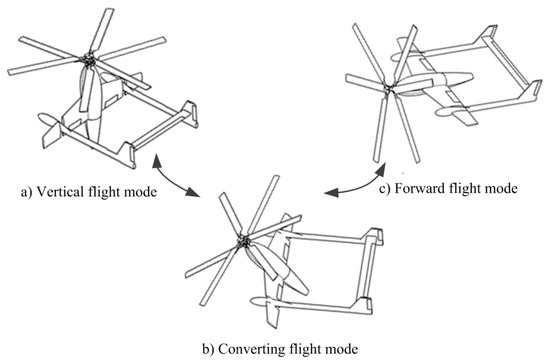
Figure 1.
The mono tiltrotor (MTR) and its three flight modes.
The aerodynamic shape designs of a traditional rotor craft are usually based on parametric studies or physical analysis [8], which rely to a large extent on experience. However, for a new concept rotor craft such as MTR, there is little relevant experience. The physical analysis method will be complex and time-consuming with such little experience. In the preliminary design stage of a new layout craft, it is difficult for designers to decide on the appropriate initial values of parameters. This paper proposes a high-efficiency automated optimization framework for MTR preliminary design by integrating aerodynamic modeling and advanced optimization algorithms. It will explore the relationship of the design parameters and help designers to determine trade-offs in the preliminary design stage.
In the design of MTR, the optimization of a coaxial rotor system plays a crucial role in achieving high efficiency in both cruising and hovering states. Single-objective optimization was applied in the design of the traditional coaxial-rotor system [9]; however, it is not able to cover most working conditions of MTR. In other words, incompatible sets of design parameters are possibly rendered for MTR in cruising and hovering, respectively [10]. A highly efficient hovering state normally requires low disk loading, while a highly efficient cruising state corresponds to a minimized drag profile of the blades and compressibility losses. Therefore, the design targets for the two states are inconsistent. Recently, few works in coaxial rotor design have focused on multi-objective design (for both hovering and cruising states), and most of them are based on parametric studies without any integrated optimization strategies [11,12]. In view of this, it is necessary to develop and validate comprehensive multi-objective optimization strategies. The goal of the present work is to construct an automated and efficient design approach for the coaxial rotor design of MTR covering multiple states in its flight envelope.
To ensure the efficiency and accuracy of the MTR’s optimization framework, two key factors—aerodynamic modeling and optimization algorithms—should be thoroughly explored. First, the blade element momentum theory (BEMT) method for MTR has been applied in the current aerodynamic modeling, owing to its high efficiency and reasonable accuracy. In detail, several aerodynamic methods—i.e., momentum theory (MT), blade element momentum theory (BEMT), free vortex method (FVM), and computational fluid dynamics (CFD)—are compared and discussed. The BEMT method is much faster than FVM and CFD, and its accuracy has been fully validated through previous experiments. Second, two optimization algorithms—i.e., adaptive simulated annealing (ASA) and non-dominated sorting genetic algorithm II (NSGA-II)—are employed, and their feasibilities for the highly non-linear and discontinuous design spaces of current MTR design have been explored. Within the selected algorithms, both single-objective and multi-objective optimizations are put forward in the current design. A corresponding aerodynamic analysis of the optimized design is also presented.
2. Aerodynamic Modeling of MTR
2.1. Numerical Methods
The aerodynamic characteristics of a coaxial rotor are complex due to the interference between the upper and lower rotors. The lower rotor operates in the slipstream of the upper rotor, while the upper rotor is affected by the suction effect from the lower rotor. Approaches to investigate the coaxial rotor aerodynamics include experimental research [13], momentum theory (MT) [14], blade element momentum theory (BEMT) [7,15], free vortex method (FVM) [9,16] and also unsteady computational fluid dynamics (CFD) based on the turbulence model [17]. In particular, MT is based on the classic momentum theory of Glauert [18], in which viscous and compressibility effects are neglected. Leishman and Syal [14] used MT to analyze a hovering contra-rotating coaxial rotor system. In FVM, a vorticity transport equation is formed under the assumption that the flow is irrotational and incompressible [9]. By directly solving unsteady Reynolds-averaged Navier–Stokes (RANS) equations, CFD is most accurate among these numerical methods. It possesses the ability to provide insight into the unsteady aerodynamic characteristics of a coaxial rotor. From the viewpoint of computational cost, CFD is most expensive, which is unrealistic for optimization design [19]. Although the computational cost of FVM is less than that of CFD, an optimization process based on FVM with a large number of cases is still intensive.
BEMT combines the blade element method with momentum theory to solve the induced velocity. It achieves a better modeling accuracy than MT by considering the spanwise distribution of the induced velocity. BEMT is applied to the investigation of certain parameters, such as the inter-rotor spacing, blades platform shapes, and blade twist. It can expeditiously and accurately predict different aerodynamic results of MTR by changing the rotor parameters. Some work was reported which has used BEMT for the aerodynamic optimization of a coaxial rotor in hovering or axial flight [9,10,11,12]. When carrying out an optimization design, the computational cost does not only come from the aerodynamic method, but also from other factors. For instance, the thrust trim and torque trim between upper and lower rotors will also require large computational resources, especially in FVM and CFD modeling. Regardless of the trim, on a desktop computer (a four-core Intel processor with CPU speeds of 3.2 GHz), a single case requires almost one day for unsteady CFD simulation; the BEMT model is more efficient, in that one individual case can be solved within several minutes. Multi-fidelity optimization techniques have always been applied to incorporate high-fidelity models into the rotor optimization loop while maintaining a moderate computational cost [20,21]. However, when considering trim, the computational cost will be increased dramatically. In view of these factors, among all the modeling approaches mentioned above, BEMT might be the most suitable and practical method for the optimization design of a coaxial rotor with a large number of samples, and it was chosen as the aerodynamic modeling tool in the current study.
The BEMT method for coaxial rotor modeling, as reported in [15], can be applied in the modeling of the current MTR. Lock [22] assumed that the wake flow of the upper rotor is affected the flow field of the lower rotor, while neglecting the lower rotor effect on the upper one. The aerodynamic interference between the upper and lower rotors, and both the upper-to-lower and lower-to-upper effects, is considered in the current work.
The BEMT modeling approach is introduced in the following section; readers can refer to [15] for more detail. As mentioned above, the BEMT modeling can be divided into two separate steps: i.e., the momentum theory step and the boundary element step.
In the momentum theory step, the flow around the rotor is assumed to be axisymmetric when the rotor is hovering, climbing vertically and cruising forward. A simplified two-dimensional theory can be used to predict the nonuniform inflow distributions. Each rotor disk is divided into several concentric rings, and the segment thrust can be obtained by the non-dimensioned advanced ratio, , and the inflow ratio, , where is the inflow velocity, is the rotating speed, R is the radius of the rotor and is the induced velocity.
where is the non-dimensional radial location. Then, the non-dimensional power coefficient of each ring is
In the boundary element step, for a single blade element, as shown in Figure 2, the incremental thrust of the rotor disk ring, , can be derived by the given lift and drag coefficients of the airfoil.
where b is the blade number, is the radial location, is the air density, is the chord length, and the inflow angle . The non-dimensional blade element thrust can be written as
where . Then, the non-dimensional power coefficient is
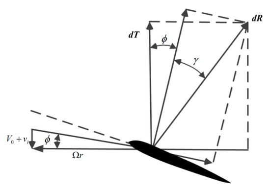
Figure 2.
Force analysis of a blade element.
BEMT constructs thrust equivalence between blade element theory and MT to solve the induced velocity. For a single rotor disk, from Equations (1) and (4), it can be obtained that
By solving Equation (6), the radial velocity distribution can be obtained. For the MTR, the induced velocity cannot be directly solved by the separate BEMT equivalent equation of the upper and lower rotors because of the interference. An interaction model between the upper and lower rotors can be constructed based on BEMT, and the mode schematic is shown in Figure 3. The Biot–Savart law shows that the induced velocity evolves with the axial spacing d as follows [7]:
where is the interference factor. The subscripts “u” and “l” are used to identify the relative parameters of the upper rotors and lower rotors, respectively. From the mass conservation law, the streamlines passing at radius on the upper rotors to the lower rotors at radius are given by
where is the interference function. In the same way, the streamlines passing at radius on the lower rotors to the upper rotors at radius are given by
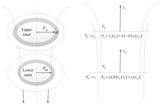
Figure 3.
Interaction model in axial flight.
Then, the interference-induced velocity for the upper and lower rotors is expressed as
The induced velocity at each rotor disk compromises two parts: i.e., its own induced velocity and the interaction induced velocity . For the MTR, the BEMT thrust equivalence of Equation (6) can be written as
From Equations (4) and (5) of blade element theory, we obtain the radial distribution of the thrust and power coefficients. The generated total thrust and consumed power by the MTR in axial flight are obtained by the summation of segment loads on upper and lower rotors, respectively:
where is the non-dimensional root cutout.
In addition, blade tip losses should be also considered properly, which will deteriorate the aerodynamic performance, since trailing vortices appear near the blade tip, and the strengths greatly increase, causing a sudden drop of lift. The Prandtl correction factor will be used [1], and it can be included in the BEMT modeling of the MTR.
The goal function in the hovering state, the figure of merit (FM), is defined as [7]
The goal function in axial flight, the propulsive efficiency (), is defined as [7]
2.2. Validation of the BEMT Modeling of MTR in Hovering State
A coaxial rotor in hovering state is simulated based on the BEMT modeling in Section 2.1. The results are validated by comparing them the experiments of Harrington [4], in which full-scale wind tunnel investigations of both single and coaxial rotors were conducted. The major rotor parameters are listed in Table 1.

Table 1.
Major information of rotors in the experiments by Harrington [4].
The power polars are presented in Figure 4a, which gives the variation of the thrust coefficient versus the power coefficient. The figure of merit (FM) is demonstrated in Figure 4b, which is the ratio of the effective thrust power to the total consumed power.
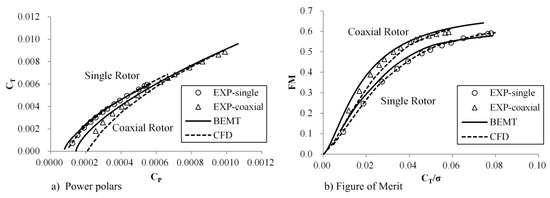
Figure 4.
Performance of rotor 2: a comparison of results by the current blade element momentum theory (BEMT), computational fluid dynamics (CFD) [19], and experiments [4] (marked as EXP).
In Figure 4, the current BEMT results are also compared with the CFD simulation of Lakshminarayan [19], which was based on compressible unsteady RANS equations with the Spalart–Allmaras turbulence model. The BEMT results agrees well with both the experimental data and CFD simulation. This confirms that BEMT is a reliable aerodynamic modeling tool for the investigation of the rotor in hovering performance. Although the FMs predicted by BEMT are a little optimistic compared to the measurement, they are still within the tolerance of the preliminarily design.
2.3. Validation of the BEMT Modeling of MTR in Axial Flight
A coaxial rotor under different axial inflow is simulated based on the BEMT modeling in Section 2.1. The results are validated with previous experiments in [23]. Detailed model parameters of this coaxial rotor are presented in Table 2. Figure 5 presents the results of the thrust coefficient and propulsive efficiency. The solid lines represent the predictions of BEMT, and the circular symbols are the experimental data. With the blade pitch angle increasing from 20° to 50° with an increment of 5°, the thrust coefficients (Figure 5a) increase accordingly. With a fixed pitch angle, reduces rapidly along with the inflow ratios. The BEMT results simulated in this paper agree very well with the measurements at small pitch angles (20°~50°). As pitch angle increases (40°~50°), the predicted does not match the experimental trend perfectly at a low inflow ratio. This is because the angles of attack for some blade sections exceed the linear aerodynamic range, where non-linear effects become more dominant. The nonlinear measurement results caused by deep blade stall at very low inflow ratios are not presented in Figure 5.
Table 2.
Major parameters of coaxial-rotor 3155-6-1.5.
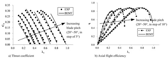
Figure 5.
Comparison of the BEMT-predicted result and experimental data for axial flight at various inflow ratios.
The propulsive efficiencies are demonstrated in Figure 5b, with blade pitches from 20° to 50° in a step of 10°. A linear dependence of and is predicted by BEMT at low inflow ratios, which is consistent with the experiments. Overall, the BEMT is also a reliable tool for the modeling of a coaxial rotor in axial flight.
3. Optimization Design of Current MTR in Hovering and Cruising Flights
3.1. Optimization Procedures
A design process coupling BEMT modeling and optimization algorithms was constructed, as shown in Figure 6. The goal was to find the optimal blade parameters with the highest efficiency for the MTR system. In this process, a design point—e.g., the thrust coefficient, , with a certain magnitude—should be decided first. The trim of both thrust and inter-rotor torque (i.e., the non-dimensional total power coefficient of upper rotor and lower rotors, and ) should be fulfilled. In particular, thrust trim was achieved by adjusting the collective pitch of the upper rotor, and torque trim was satisfied by adjusting the corresponding lower rotor’s collective pitch. The classic dichotomy method in [24] was utilized to solve the trim procedure, and the convergence was determined by the tolerances and , as shown in Figure 7.
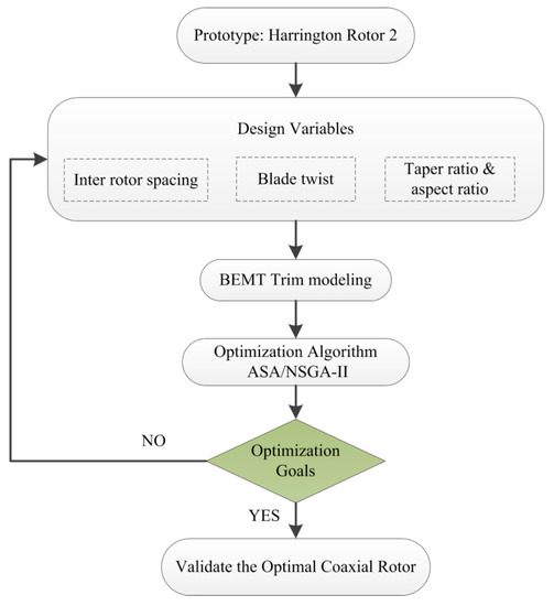
Figure 6.
Framework of the optimization procedure for the mono tiltrotor (MTR) design. ASA: adaptive simulated annealing; NSGA-II: non-dominated sorting genetic algorithm II.
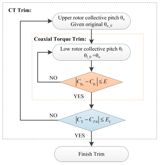
Figure 7.
Coaxial trim in BEMT modeling ( is the total thrust coefficient).
Two single-objective optimization cases (for MTR in hovering or in cruising states) and a multi-objective optimization case (for MTR in both hovering and cruising states) are conducted at certain design points. The inter rotor spacing, blade twist, taper ratio (TR) and aspect ratio (AR) are chosen as design variables, while the blade solidity and blade number are fixed. The definitions of TR and AR are
where , and are the lengths of the tip chord, root chord and mean aerodynamic chord, respectively (as shown in Figure 8).
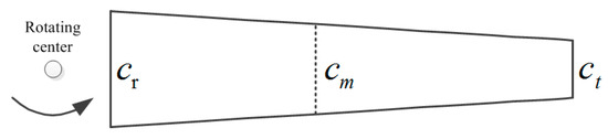
Figure 8.
Chord of rotor platform.
A practical design of the MTR has to allow certain constraints, such as the overall rotor weight, limitation of the blade tip speed, and maximum allowable blade twist. According to previous experience [8,9], constraints of certain parameters are listed in Table 3, where is the blade twist from root to tip. Coaxial rotor 2 in [4] is chosen as the baseline design of MTR in this optimization. The best design of a coaxial rotor may require different blade twists and platforms for each rotor [9]. However, considering the structural symmetry and design consistency of the MTR system, the blade twist and platform of each rotor are kept the same in the current design. In addition, the ideal blade twist is hyperbolic or double hyperbolic [25], while only linear blade twists are considered here for simplification.
Table 3.
Constraint conditions of design variables.
3.2. Optimization Algorithms
For an optimization project, the key to success is the selection of an appropriate optimization algorithm. Two core factors, accuracy and efficiency, are considered here when selecting the optimization methods. The aerodynamic design of MTR is a highly non-linear and discontinuous design problem. The adaptive simulated annealing (ASA) algorithm with open source code is used for the single-objective optimization of the MTR in hovering or cruising states. The ASA algorithm is very well suited to solving non-linear and discontinuous problems. In the current work, the non-dominated sorting genetic algorithm II (NSGA-II) is applied for the multi-objective optimization design of the MTR in both hovering and cruising states. NSGA-II is chosen here because of its high efficiency, fast convergence, good fitness properties and uniformly distributed Pareto front. It is also well suited to the highly non-linear and discontinuous design spaces in the MTR design.
3.2.1. Adaptive Simulated Annealing Algorithm for Single-Objective Optimization
Adaptive simulated annealing (ASA) is a global optimization algorithm that relies on a random importance-sampling parameter space, which can be sampled much more efficiently than by using traditional annealing algorithms. The ASA code released by Ingber [26] is used for the single-objective optimization of the MTR in hovering or cruising states. The ASA algorithm is very well suited to solving non-linear and discontinuous problems with short running analysis codes. It has been applied for aircraft research [27] and is chosen here for MTR design.
The parameters of ASA are selected according to [26]. The maximum number of generated designs is set as 700. Other parameters, such as relative rate of parameter annealing, cost annealing, parameter quenching, cost quenching and so forth, use default values in the ASA code.
3.2.2. Non-Dominated Sorting Genetic Algorithm II for Multi-Objective Optimization
Genetic algorithms have been widely used for the multidisciplinary optimization of rotor design for a long time [28], because of their distinct advantages of using discrete points to search the entire design space. A Pareto front is always obtained by multi-objective optimization algorithms to make trade-offs within the set of design parameterizations that are all Pareto-efficient. In the Pareto front, each design has the “optimal” combination of objective values, and improving one objective is impossible without sacrificing one or more of the other objectives. The non-dominated sorting genetic algorithm II (NSGA-II) [29] has been widely applied for rotor design [30,31,32]. In this project, NSGA-II is applied for the multi-objective optimization design of the MTR in both hovering and cruising states. In NSGA-II, each objective parameter is treated separately, and a Pareto front is constructed by selecting feasible non-dominated designs. The monitoring of convergence to the Pareto-optimal is set in the NSGA-II program. In the NSGA-II program, A performance metric, γ, has been defined to evaluate the convergence to the Pareto-optimal.
NSGA-II utilizes fast non-dominated sorting technology to decrease the computational complexity and is based on an elitist mechanism to improve accuracy. In the current optimization process, the population size N is set to 40, and 20 generations are created to obtain the last Pareto front.
The main parameters of NSGA-II include the population size N, number of generations, crossover probability, cross over distribution index, and mutation distribution index. The setting of the last three parameters was based on those in [29,33] The crossover probability was 0.9, and the distribution indexes for crossover and mutation were 20 and 20, respectively.
3.3. Realization of Optimization
The realization of the current method can be described by the following flow chart in Figure 9. It includes two major modules: i.e., the trim modeling by BEMT and the optimization design.
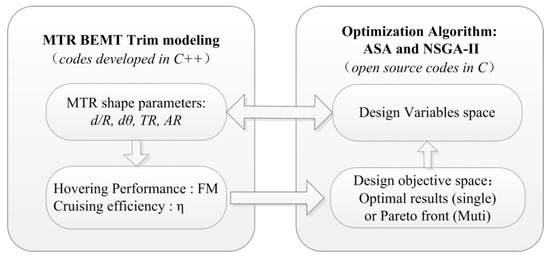
Figure 9.
Two main modules of MTR optimization system. FM: figure of merit.
For the module of trim modeling, the authors developed the BEMT code based on the theory as illustrated in Section 2.1 and Figure 7 in the manuscript. For the module of optimization design, both algorithms (ASA and NSGA-II) were employed from the well-developed theories [24,26] and open source codes. The detailed procedure is as follows: first, the initial values of shape parameters, such as d/R, dθ, TR, AR, are input by the designers, which are shared to the design variables space of the optimization design module. Second, the hovering performance FM and cruising efficiency η can be solved by BEMT trim modeling, and the results are then sent to the design objective space of the optimization algorithm module. Third, the optimization algorithm will decide the design parameters of the next group/generation and feed back to the BEMT trim modeling module. This circle is actuated by optimization algorithms and does not stop until the preset generation number is finished. This optimization project can be implemented in existing design optimization platforms such as Isight software and Artap [34] to validate the results.
The time consumption of a case varies within a certain range, which relies on each set of parameters. One individual case requires almost 1~2 minutes, and one optimization process can be finished within one day (with 800 samples, on a computer of a four-core Intel processor with CPU speeds of 3.2 GHz).
3.4. Analysis of 0ptimization Results
3.4.1. Single-Objective Optimization in Hovering or in Cruising States
Two single-objective optimization cases for the current MTR in hovering or in cruising states are conducted. For the target thrust coefficient, the hovering trim is and cruising trim is . The trim tolerances are set as and , respectively. Both single-objective optimization cases are based on the ASA optimization algorithm with 700 samples.
Figure 10 gives the hovering FM and cruising η in each optimization process. Under the design constraints (as shown in Table 3), both optimization objectives converge to the optimal goals after a certain number of samples. The best FM for hovering optimization is 0.6846, and the optimal η for cruising optimization is 0.6514.
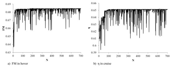
Figure 10.
Optimization samples in hovering and cruising state based on ASA (N is the population size).
Figure 11 and Figure 12 illustrate the design parameter distribution versus objectives of all the samples. All the design parameters gather to certain values (marked with a red circle in each figure), which are given in the third and fourth columns in Table 4. Several points can be observed in the optimization results: 1) the optimal taper ratios for both hovering and cruising cases reach the lower constraint limit, since smaller TRs contribute to more uniformly induced velocity distributions along each blade; 2) the optimal radii for both cases are close to the upper constraint limit—obviously, longer and thinner blades have less inter-blade interference; 3) the best linear blade twists for the hovering case (−11.4) and cruising case (−18.2) are divergent, which results from their different reset trim thrusts—a suitable blade twist design can decrease the induced losses on the coaxial rotor, and it can distinctly delay flow separation at the blade root and stall at the blade tip, which will contribute to a more uniform load distribution on each blade [10]. However, a large blade twist will be unproductive, since it induces more serious flow stall along the blade; 4) for inter-rotor spacing, distinct gathering can be seen in the cruising case, which is at the lower limit 0.14, but no clear trend is found in hovering case. Compared with the previous three design parameters, the inter-rotor spacing has a relatively weak influence. According to the intrinsic mechanism, a larger spacing may contribute to less interference losses, but it also leads to higher profile drag with a higher exposed shaft.
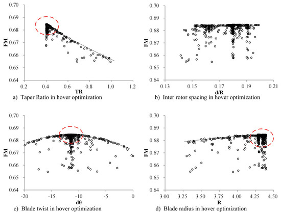
Figure 11.
Parameters of optimization samples in hovering state.
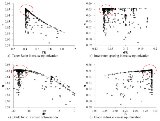
Figure 12.
Parameters of optimization samples in cruising state.
Table 4.
Parameters of original and single/multi-objective optimized rotors.
It can be found that the performance in both cases is obviously affected by the design constraints. The single-objective optimization results give clear indications of the effects of each design parameter and their correlations. The optimizations of the hovering case and cruising case result in different selections of design parameters. Trade-offs of design parameters should be carefully considered when both hovering and cruising performances are concerned. Therefore, a multi-objective optimization is possibly required.
3.4.2. Multi-Objective Optimization for the MTR in Both Hovering and Cruising States
In the multi-objective optimization process, the figure of merit (FM) in the hovering sate and the propulsive efficiency (η) in the cruising state are chosen as objective functions. Sensitivity analysis under different sets of generation numbers was implemented for the multi-objective optimization. Two optimization cases with 20 and 30 generations (both with population size N = 40) have been carried out, respectively. The results in Figure 13 show that the 30-generations case shares a similar Pareto Front to the 20-generation results, which indicates that 20 generations are sufficient in the current optimization. The following analysis will focus on the case with 20 generations.
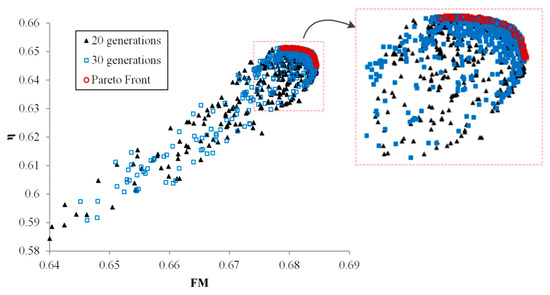
Figure 13.
Sensitivity analysis results under different generation numbers in multi-objective optimization (the Pareto front in the red circle is from the 20 generations case.).
Figure 14a shows the detailed multi-objective optimization results which are obtained by the NSGA-II algorithm, where a total number of 800 samples is utilized to obtain the last Pareto Front (Figure 14b). Among all these samples, the maximum FM for the hovering case is 0.6845 and the maximum η for the cruising case is 0.6513. They appear in different design samples, and both of them are smaller than those in the single-objective optimization cases. Designers can make trade-offs among the design points on the Pareto front. For example, if the cruising performance is investigated, an optimal design from the optimized cruising side of the Pareto front can be selected, as marked in Figure 14b. This optimal design has almost the highest cruising efficiency with a moderate hovering FM. This specific example design has been used as a case study and in the parameter analysis in the following sections. The parameter comparison of the original and optimized rotor (optimal choice in Figure 14b) is listed in the second and fifth columns of Table 4.
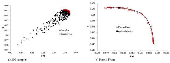
Figure 14.
Multi-objective optimization results based on NSGA-II (20 generations).
Figure 15 demonstrates the design parameters along the Pareto front in the current multi-objective optimization. TR is around 0.4 along the entire Pareto front (Figure 15a), which is consistent with the single-objective optimization results. In Figure 15b, when the Pareto front inclines to the cruising-optimized side, the distribution of the inter-rotor spacing is relatively scattered, and it converges to 0.18 when it moves towards the optimized hovering side. Figure 15c indicates that larger blade twists (a larger absolute value of ) are more suitable for cruising, whereas relatively smaller twists are better for hovering. The last sub-figure shows that most of the optimal blade radii along the Pareto front are close to 4.40. Besides, radii within the range of 4.25 to 4.40 are also suitable for hovering.
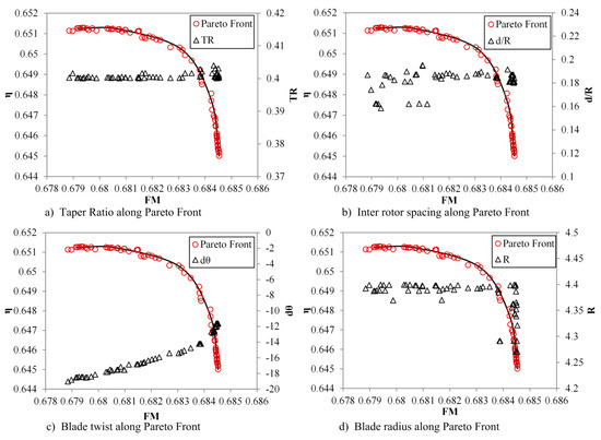
Figure 15.
Parameters along the Pareto front in multi-objective optimization.
The aerodynamic mechanism analysis and discussion of results will focus on the multi-objective optimization design (the optimal choice in Figure 14b). As shown in the last column of Table 4, the optimized blades of MTR are thinner and longer than the original one under the same blade solidity and blade number. Unlike the original rectangular blade platform, the optimized rotor platform is trapezoidal. Its AR reaches the upper limit of 8.6, while its TR reaches the lower limit of 0.4. The other two design variables—i.e., the inter rotor spacing and blade twist—are determined by the trade-offs between the hovering FM and cruising η. For the chosen optimized rotor, the inter rotor spacing is 0.18 and the linear blade twist is −17.6°.
Under the presupposed design point—i.e., hovering trim and cruising trim —the optimized MTR has a performance of FM = 0.6805 and η = 0.6512. Compared with the original rotor (FM = 0.6343, η = 0.5745, for coaxial rotor 2 in [4]), FM and η have been improved by 7.3% and 13.4%, respectively. It is also worth mentioning that a compromise design is directly obtained from the multi-objective optimization, while the single-objective optimizations always present biased designs (as shown in the last two rows in Table 4) with either a worse FM or a worse efficiency.
The hovering FM and cruising η under a series of trim thrust coefficients are investigated to compare the global performance of the optimized MTR with the original one. As shown in Figure 16, the effects of optimization are obvious in both hovering and cruising states, During the entire calculated range, the maximum performance increments for hovering are = 14.1% and those for cruising are = 25.0%.
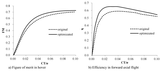
Figure 16.
Global performance comparison of the original and optimized MTR in hovering and cruising states.
Figure 17 and Figure 18 illustrate the span-wise load distributions—i.e., the thrust coefficient, , and torque coefficient, —on the upper and lower rotors of the original and the multi-objective optimized MTR, respectively. In these figures, solid lines with solid symbols are the results of the optimized MTR, and dashed lines with hollow symbols are those of the original rotor. In addition, the triangle symbols correspond to the upper rotor and circular symbols correspond to the lower rotor. Figure 17a shows that most of the upper rotor thrusts are larger than the lower ones, which results from the effects of induced speed in the hovering state, while in the cruising state, as shown in Figure 18a, the upper rotor thrust distribution is very close to the lower one because, at that time, the inflow caused by forward speed plays a dominant role. For the torque distribution in the hovering state, as shown in Figure 17b, distributions on the upper and lower rotors remain consistent with each other due to the torque trim in the optimization process. The same phenomenon is seen in Figure 18b for cruising flight. In conclusion, compared with the original MTR, the optimized MTR has a much more uniform load distribution along the blade span, which contributes to much better performance both in hovering and cruising states.
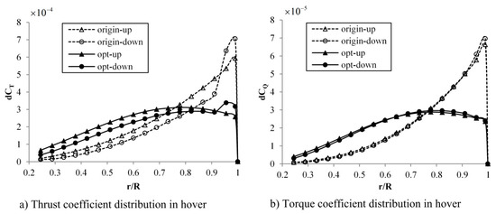
Figure 17.
Spanwise load distribution on the upper and lower rotors of the optimized MTR in the hovering state.
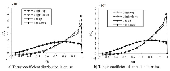
Figure 18.
Spanwise load distribution on the upper and lower rotors of the optimized MTR in the cruising state.
4. Conclusions
In this paper, the BEMT method was applied in the aerodynamic modeling of an MTR coaxial rotor system. As part of this analysis, the interference between the upper and lower rotors was accounted for. The accuracy of the current BEMT modeling is fully validated by a comparison with previous experimental data and CFD simulation, confirming that BEMT is a reliable tool for aerodynamic modeling and the optimization design of MTR. A high-efficiency automated optimization framework was then built by integrating the BEMT modeling and advanced optimization algorithms; i.e., single-objective optimization and multi-objective optimization. The trim of both thrust and torque was fulfilled during the optimization process.
The single-objective optimizations of the rotor in either hovering or cruising states were independently studied. Both cases led to better aerodynamic performances of the rotor with their specific working conditions; i.e., the figure of merit (FM) was improved from 0.6343 to 0.6846 in the hovering state, or the propulsive efficiency (η) was improved from 0.5745 to 0.6514 in the cruising state. The single-objective optimization results clearly show the effects of each parameter and their inter-relationships on design objectives. It was found that the optimal design parameters of these two cases deviate from each other, which is not applicable in the realization of aircraft design.
The multi-objective optimization, considering both hovering and cruising performance, is studied. A Pareto front is obtained from this project. The design parameter analysis along the Pareto front shows that AR reaches the upper limit of 8.6, while TR reaches the lower limit of 0.4. The other two design variables—i.e., the inter-rotor spacing and blade twist—are determined by the trade-offs between the hovering FM and cruising η. When the Pareto front inclines to the cruising-optimized side, the distribution of the inter-rotor spacing is relatively scattered, and it converges to 0.18 when moving towards the hovering-optimized side. Larger blade twists are more suitable for cruising, whereas relatively smaller twists are better for hovering. An example design point has been chosen from the Pareto front samples. Further analysis showed that the optimized design possessed a performance of FM = 0.6805 and η = 0.6512, which was improved by 7.3% and 13.4% from that of the prototype, respectively. A comprehensive performance in both hovering and cruising states is achieved in multi-objective optimization, in which the single-objective optimization cases only render a biased optimization design. The multi-objective optimized rotor platform is trapezoidal; its AR arrives to the upper limit, while its TR reaches to the lower limit. The optimized rotor has a uniform load distribution along the blade span, and therefore it contributes to a better performance in both hovering and cruising states.
The optimized design has increased the hovering performance, FM, by 7.3% and the cruising performance η by 13.4% when compared with the prototype, respectively. The payload capability is in direct proportion to the hovering FM. On the other hand, the rate of climb will also be increased with the FM. Cruising η is the ratio of effective power and total power; a higher η means more fuel savings. The endurance of cruising will be increased by almost 10% after optimization. In addition, the maximum fight speed will be distinctly improved by the increase of η. In summary, the optimization project in the current work can achieve the original goal of MTR, which is to expand the overall flight envelope for a rotor craft.
In general, there are three flight modes of the MTR: i.e., forward flight, vertical flight and converting flight. The current work mainly focuses on the BEMT aerodynamic modeling in the hovering state and axial flight, corresponding to the vertical flight and forward flight modes. The flow around the coaxial rotor is axisymmetric in the hovering state and axial flight, while for converting flight, an oblique flow acts on the coaxial rotor. The flow around the coaxial rotor is not axisymmetric. Several changes should be made to apply the BEMT model to inclined flow. First of all, three-dimensional rather than two-dimensional theory should be applied in the momentum theory of BEMT. Secondly, the aerodynamic interference areas both in the upper rotor and lower rotor are not circular, as with those in Figure 3. Both shapes of interference from the upper rotor and the lower rotor are irregular. Therefore, the calculation method of interference areas in axial flight should be changed when applied to converting flight. Improved aerodynamic modeling should be explored for the converting flight mode in future work.
Author Contributions
Conceptualization, L.Z., J.H., D.P. and X.S.; Data curation, L.Z.; Formal analysis, L.Z., D.P. and X.S.; Funding acquisition, J.H. and D.P.; Investigation, L.Z. and J.H.; Methodology, L.Z.; Supervision, D.P. and X.S.; Writing—original draft, L.Z.; Writing—review & editing, J.H., D.P. and X.S. All authors have read and agreed to the published version of the manuscript.
Funding
This research was funded by National Natural Science Foundation of China, grant number 51906224, and Zhejiang Provincial Natural Science Foundation, China, grant numbers LY18A020002.
Conflicts of Interest
The authors declare no conflict of interest.
References
- Wayne, J. Helicopter Theory; Princeton University Press: Princeton, NJ, USA, 1980. [Google Scholar]
- Bolkcom, C. V-22 Osprey Tilt-Rotor Aircraft. 2005. Available online: https://www.everycrsreport.com/files/20050804_RL31384_31272dfc23e2ff48a9e152b7caa0adcf3a100e5c.pdf (accessed on 18 January 2020).
- Baldwin, G.D.; Washington, P. Preliminary Design Studies of a Mono Tiltrotor (MTR) with Demonstrations of Aerodynamic Wing Deployment. In Proceedings of the AHS International Specialists Meeting, Chandler, AZ, USA, 23–25 January 2007. [Google Scholar]
- Harrington, D. Full-scale-tunnel investigation of the static-thrust performance of a coaxial helicopter rotor. In NACA TN-2318; Langley Field: Hampton, VA, USA, 1951. [Google Scholar]
- Bohorquez, F. Rotor Hover Performance and System Design of An Efficient Coaxial Rotary Wing Micro Air Vehicle. Ph. D. Thesis, University of Maryland, College Park, MD, USA, 2007. [Google Scholar]
- Bagai, A. Aerodynamic design of the x2 technology demonstrator main rotor blade. In Proceedings of the 64th American Helicopter Society Annual Forum, America Helicopter Society, Montreal, QC, Canada, 29 April–1 May 2008; pp. 29–44. [Google Scholar]
- Leishman, J.G. Aerodynamic performance considerations in the design of a coaxial proprotor. J. Am. Helicopter Soc. 2009, 54, 12005. [Google Scholar] [CrossRef]
- Leishman, J.G. Principles of Helicopter Aerodynamics, 2nd ed.; Cambridge University Press: New York, NY, USA, 2006; pp. 125–140. [Google Scholar]
- Syal, M.; Leishman, J.G. Aerodynamic optimization study of a coaxial rotor in hovering flight. J. Am. Helicopter Soc. 2012, 57, 1–15. [Google Scholar] [CrossRef]
- Leishman, J.G.; Rosen, K.M. Challenges in the aerodynamic optimization of high-efficiency proprotors. J. Am. Helicopter Soc. 2011, 56, 12004. [Google Scholar] [CrossRef]
- Rand, O.; Khromov, V. Aerodynamic optimization of coaxial rotor in hover and axial flight. In Proceedings of the 27th International Congress of the Aeronautical Sciences, Nice, France, 19–24 September 2010; pp. 1–13. [Google Scholar]
- Leishman, J.G.; Ananthan, S. Aerodynamic optimization of a coaxial proprotor. In Proceedings of the 62th American Helicopter Society Annual Forum, American Helicopter Society, Phoenix, AZ, USA, 9–11 May 2006; Volume 1, p. 64. [Google Scholar]
- Coleman, C.P. A Survey of Theoretical and Experimental Coaxial Rotor Aerodynamic Research. 1997. Available online: https://ntrs.nasa.gov/archive/nasa/casi.ntrs.nasa.gov/19970015550.pdf (accessed on 15 October 2019).
- Leishman, J.G.; Syal, M. Figure of merit definition for coaxial rotors. J. Am. Helicopter Soc. 2008, 53, 290–300. [Google Scholar] [CrossRef]
- Valkov, T.Y. Aerodynamic load computation on coaxial hingeless helicopter rotor. In Proceedings of the 28th Aerospace Sciences Meeting, Reno, NV, USA, 8–11 January 1990. [Google Scholar]
- Yana, J.; Rand, O. Performance analysis of a coaxial rotor system in hover: Three points of view. In Proceedings of the 28th International Congress of the Aeronautical Sciences, Brisbane, Australia, 23–28 September 2012. [Google Scholar]
- Pérez Gordillo, A.M.; Villegas Santos, J.S.; Lopez Mejia, O.D.; Suárez Collazos, L.J.; Escobar, J.A. Numerical and Experimental Estimation of the Efficiency of a Quadcopter Rotor Operating at Hover. Energies 2019, 12, 261. [Google Scholar]
- Glauert, H. Airplane propellers. In Division L in Aero-Dynamic Theory Vol.4; Durand, W.F., Ed.; Springer: Berlin, Germany, 1935; pp. 169–360. [Google Scholar]
- Lakshminarayan, V.; Baeder, J. Computational investigation of small scale coaxial rotor aerodynamics in hover. In Proceedings of the 47th AIAA Aerospace Sciences Meeting Including the New Horizons Forum and Aerospace Exposition, Orlando, FL, USA, 5–8 January 2009; p. 1069. [Google Scholar]
- Leusink, D.; Alfano, D.; Cinnella, P. Multi-fidelity optimization strategy for the industrial aerodynamic design of helicopter rotor blades. Aerosp. Sci. Technol. 2015, 42, 136–147. [Google Scholar] [CrossRef]
- Collins, K.B. Multi-Fidelity Framework for Physics Based Rotor Blade Simulation and Optimization. Ph.D. Thesis, Georgia Institute of Technology, Atlanta, GA, USA, 2008. [Google Scholar]
- Lock, C. Interference Velocity for A Close Pair of Contra-Rotating Airscrews; British HM Stationery Office: London, UK, 1941. [Google Scholar]
- Maynard, J.D. Wind-tunnel tests of single-and dual-rotating tractor propellers of large blade width. Tech. Rep. Arch. Image Libr. 1942, 727, 319–347. [Google Scholar]
- Knuth, D.E. The Art of Computer Programming: Sorting and Searching; Addison-Wesley Professional: Englewood Cliffs, NJ, USA, 1998. [Google Scholar]
- Leishman, J.G.; Ananthan, S. An optimum coaxial rotor system for axial flight. J. Am. Helicopter Soc. 2008, 53, 366–381. [Google Scholar] [CrossRef]
- Ingber, L. Adaptive simulated annealing (ASA): Lessons learned. J. Control. Cybern. 1995, 25, 33–54. [Google Scholar]
- Bouttier, C.; Babando, O.; Gadat, S.; Gerchinovitz, S.; Laporte, S.; Nicol, F. Adaptive Simulated Annealing with Homogenization for Aircraft Trajectory Optimization. J. Oper. Res. Soc. Am. 2017, 569–574. [Google Scholar] [CrossRef]
- Hajela, P.; Lee, J. Genetic algorithms in multidisciplinary rotor blade design. In Proceedings of the 36th Structures, Structural Dynamics and Materials Conference, New Orleans, LA, USA, 10–13 April 1995; pp. 2187–2197. [Google Scholar]
- Deb, K.; Pratap, A.; Agarwal, S.; Meyarivan, T. A fast and elitist multi-objective genetic algorithm: Nsga-ii. IEEE Trans. Evol. Comput. 2002, 6, 182–197. [Google Scholar] [CrossRef]
- Liu, Z.; Dong, L.; Moschetta, J.M.; Zhao, J.; Yan, G. Optimization of Nano-Rotor Blade Airfoil Using Controlled Elitist NSGA-II. Int. J. Micro Air Veh. 2014, 6, 29–42. [Google Scholar] [CrossRef]
- Sessarego, M.; Dixon, K.R.; Rival, D.E.; Wood, D.H. A hybrid multi-objective evolutionary algorithm for wind-turbine blade optimization. Eng. Optim. 2015, 47, 1043–1062. [Google Scholar] [CrossRef]
- Jiang, H.; Zhou, Z.; Jia, Y.; Zhang, Y.; Zhang, F. Coordinated Optimization of DFIG Rotor Crowbar and DC-chopper Resistances Based on NSGA-II. Energy Procedia 2019, 18, 589–594. [Google Scholar] [CrossRef]
- Deb, K.; Agrawal, R.B. Simulated binary crossover for continuous search space. Complex Syst. 1995, 9, 115–148. [Google Scholar]
- Panek, D.; Tamas, O.; Pavel, K. Artap: Robust design optimization framework for engineering applications. arXiv 2019, arXiv:1912.11550. [Google Scholar]


© 2020 by the authors. Licensee MDPI, Basel, Switzerland. This article is an open access article distributed under the terms and conditions of the Creative Commons Attribution (CC BY) license (http://creativecommons.org/licenses/by/4.0/).