Article

Comparative Analysis of Small-Scale Integrated Solar ORC-Absorption Based Cogeneration Systems

School of Architecture and Civil Engineering, Xiamen University, Xiamen 361005, China
*
Author to whom correspondence should be addressed.
Energies 2020, 13(4), 946; https://doi.org/10.3390/en13040946
Submission received: 16 January 2020 / Revised: 13 February 2020 / Accepted: 18 February 2020 / Published: 20 February 2020

Abstract

:
This paper aims to present a comparative study into the cascade and series configurations of the organic Rankine cycle based small-scale solar combined cooling, heating and power system for civil application. The energy performance of the systems is studied by developing a thermodynamic model. The simulation model is validated using the literature results. Analyses of the research results indicated that the cascade system can achieve maximum value of the primary energy efficiency of 13.4% for cooling and power generation under solar collecting temperature of 115 °C in cooling mode. The cascade system has more cooling output and less electricity output in cooling mode compared with the series system. In heating mode, the single solar organic Rankine cycle (ORC) operation can achieve highest primary energy efficiency of 19.6% for heating and power generation under solar collecting temperature of 100 °C. Systems with R141b as ORC working fluid show better performance than those with R123 and R1233zd(E).

Graphical Abstract

1. Introduction

Building sectors consumed a large amount of non-renewable energy resources. Regarded as one of the most feasible renewable solutions for the building application, solar thermal technology is proven to be the most mature technology among all currently available solar technologies, for meeting building’s electricity and hot water demand. Solar thermal driven combined cooling, heating and power systems (CCHP) can simultaneously produce multiple energy (electricity, heating and cooling) to meet building’s multi-energy demands. In these systems, fuel cell, steam turbine or organic Rankine cycle (ORC) is usually used for power generation while absorption or adsorption chiller is used for cooling generation.
In the last decade, many researchers studied the combined cooling, heating and power system experimentally and numerically. ORC is considered to be a useful technique to convert low-grade thermal energy into electricity [1]. Riffat and Zhao [2] assessed the performance of a heating-cogeneration system using ORC and the overall efficiency of the system was 59%. Using binary mixtures as working fluids is one way to produce useful cooling and power energy. Goswami proposed a cycle for simultaneously power and cooling production with ammonia-water mixture as working fluid [3]. The maximum effective coefficient of performance (COP) of Goswami Cycle is near 1.1 when compared to work-optimized results [4]. Zare et al. [5] carried out thermoeconomic analysis and optimization of an ammonia-water power/cooling cogeneration cycle. They found that the sum of the unit costs of the products is reduced by about 18.6% for the cost optimal design compared to that of the thermal efficiency optimal design.
Integration of ORC [6] and the absorption cycle has been considered in many recent studies. Cho et al. [7] carried out a review on CCHP system to synthesize current status of CCHP research regarding to energetic and exergetic analyses, optimization methods and emerging trends. Salek et al. [8] presented a thermodynamic analysis of a hybrid ORC and ammonia absorption cycle to recover the energy of engine exhaust gas. Kanoglu and Dincer [9] considered four cogeneration plants for buildings involving the generation of electricity and heat. In addition, several arrangements of CCHP systems based on biomass [10], fuel cell [11,12] and waste heat recovery [13,14,15] have been studied and relevant energy and exergy analyses have been carried out. For CCHP systems driven by solar energy, Al-Sulaiman et al. [16] analysed a proposed solar driven CCHP system and found that the maximum efficiency can reach 94%. Wang et al. [17] proposed a solar driven CCHP system combining a Rankine cycle and an ejector refrigeration cycle, and found that the system can achieve a maximum exergy efficiency of 60.33% under the conditions of the optimal slope angle and hour angle. Eisavi et al. [18] investigated a CCHP system driven by solar energy integrated ORC and lithium bromide-water absorption refrigeration system. The cogeneration heat and power efficiency of the combined system reached 96.0%. Settino et al. [19] provided an overview of the main solar technologies to provide heating, cooling and electricity. Zhao et al. [20] explored the effects of CCHP system configurations with an ORC of 200 kW, which are clarified into sequential and parallel connections, on the system’s thermodynamic performance. The study focused mainly on the solar parabolic trough collector (PTC), which required a tracking system, to produce heat with temperature of 150 °C to 300 °C.
As the combined cooling, heating and power system can improve the solar energy utilization ratio and match solar energy supply and energy use, it has attracted the increasing research interests. While most of the present studies referred to large scale plants [21], which were relatively mature technologies [22], a few researches focused on small-scale CCHP systems, for example the small-scale ORC expander [23], the solar micro-CCHP based on dual-ORC [24], the small-scale concentrated solar combined heat and power system [25], the domestic scale solar-powered ORC and vapour compression cycle coupled system [26]. Small-scale systems were considered a relatively more suitable solution for building applications [27]. To further understand the insights of such technology for civil applications, such as residential buildings, a comparative investigation into the thermal performance of cascade and series configurations of a small-scale CCHP system will be carried out. Furthermore, compound parabolic concentrator (CPC) with a larger acceptance angle and without a tracking requirement is used to reduce the cost and complexity of the system [28]. Thermal performance of the systems will be presented, as well as thermo-fluid analyses, numerical model development, model running up, modelling result analyses. The system configurations will be described in Section 2.

2. System Descriptions

The proposed designs of the systems contain a CPC solar collector, a heat storage tank, an ORC and a single-effect absorption heat pump. The designs are classified into cascade system (CS) and series system (SS). The operational mode of the CCHP system is designed to generate cooling and power in cooling mode while generating heating and power in heating mode.
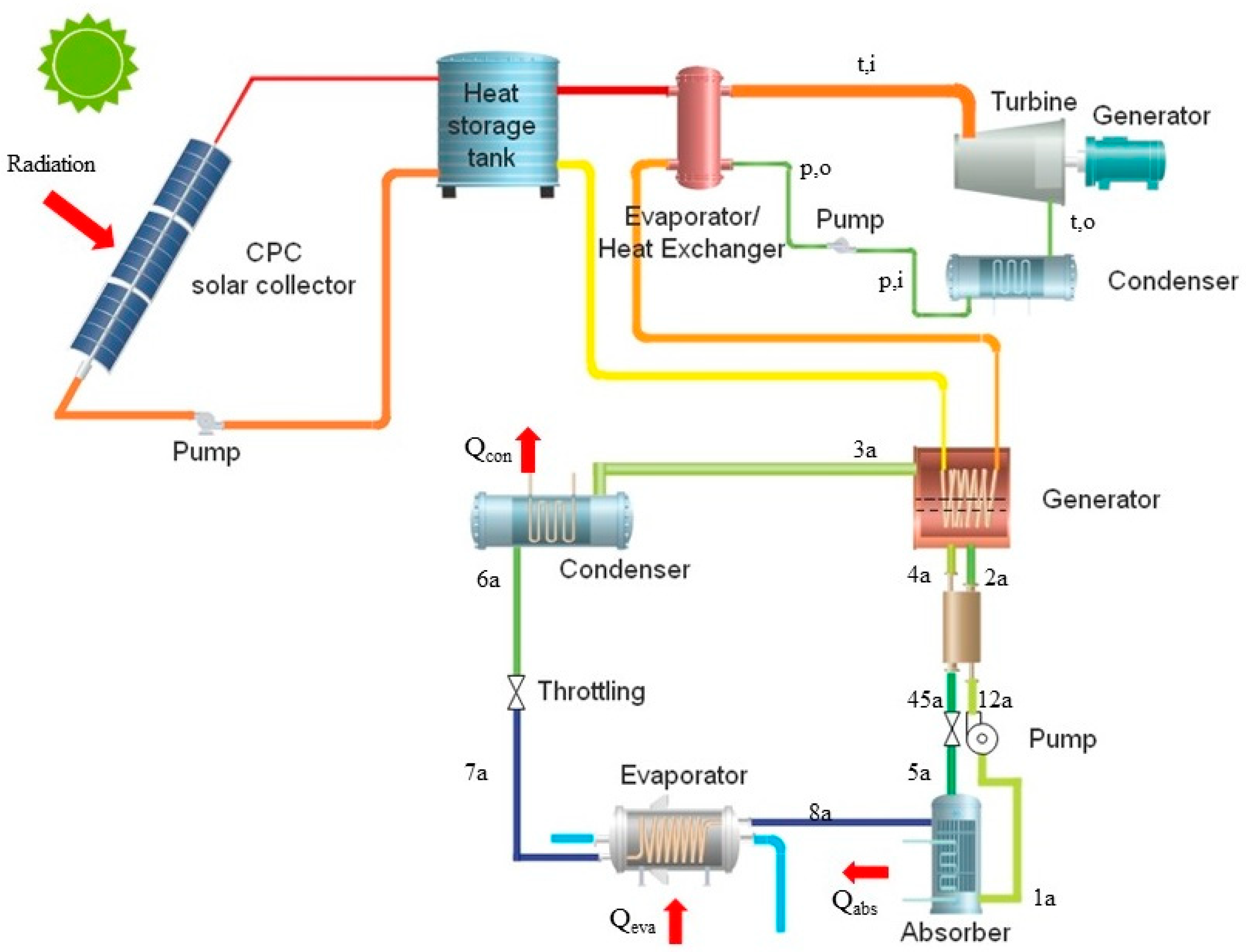
Figure 1 shows the schematic diagram of the cascade system (CS). Compound Parabolic Collector (CPC) collectors absorb solar radiation heat energy and transfer to thermal oil. In the system, thermal oil absorbs solar heat energy from Compound Parabolic Collector (CPC) collectors and releases heat to the heat storage tank. The heat transfer fluid carries heat from the heat storage tank to the ORC evaporator/heat exchanger and vaporises the working fluid within the ORC evaporator. In the ORC cycle, superheated vapour working fluid (t,i) expands to condensation pressure (t,o) through the expander and generates electricity due to the enthalpy drop. Within the condenser of ORC (generator of absorption cycle), the vapour is condensed into liquid at the same temperature, releasing the condensation heat. Meanwhile, the condensed liquid out of the condenser (p,i) is pumped to higher pressure (p,o) and flows back to the evaporator. In the absorption cycle, the working pair and the refrigerant are LiBr-H2O and water/steam, respectively. The generator of the absorption cycle absorbs heat rejected from ORC and produces cooling effect in the evaporator while rejecting heat in the condenser and absorber. The ORC system is set up as a topping sub-system that absorbs all thermal oil rejected energy, while absorption system is set up as a bottoming sub-system. In cooling mode, evaporator produces cooling as useful energy, while in heating mode condenser and absorber produce desired heating energy. A configuration of single solar ORC without absorption cycle, in which the condenser of ORC is considered to provide heat energy to users, is also comparatively studied for heating mode.
Figure 2 shows the configuration of the series system (SS), where the ORC system acts as a front subsystem and absorption system acts as a rear subsystem. In this way, the entire mass flow rate of the thermal oil absorbs the solar energy and then rejects heat to ORC and absorption system sequentially. The ORC sub-system and the absorption cycle of SS are both powered by thermal oil, where ORC system is driven by higher temperature thermal oil and absorption cycle by lower temperature thermal oil. The driven temperature for absorption cycle is limited by the outlet temperature of the thermal oil out of the ORC evaporator.

3. Mathematical Analyses

In this study, a numerical model for the combined solar cooling heating and power systems was developed based on the principles of thermodynamic. The model comprises three subsystem models: CPC solar collector model, ORC model and absorption system model. The following assumptions have been applied:
  • The system is considered to operate at steady state.
  • The refrigerant flows inside all components of the system is simplified as one-dimensional form.
  • Heat losses from the working fluid transportation lines, ORC turbine and pumps to the ambient are neglected.
  • The isentropic efficiencies of the ORC turbine and pumps are fixed at a constant value.
  • The working fluids flow within all components of the system are considered as homogeneous mixtures. The thermal and physical properties are calculated as the averaged values of each substance.
  • The working fluid exiting the condenser and evaporator of the absorption cycle is assumed at its saturated condition. Superheated vapour steam from generator of the absorption cycle is pure steam without LiBr substance.

3.1. CPC Solar Collector Model

A CPC solar collector can absorb both beam and diffuse radiation. The thermal efficiency of the CPC collector is expressed as [29]:
η = η 0 A G ( T T a ) B G ( T T a ) 2
where η0 is the optical conversion of CPC, 0.661, A is the first heat loss coefficient of CPC collectors, 0.82 W/m2K and B is the second heat loss coefficient of collectors of CPC collectors, 0.0064 W/m2K [29].

3.2. ORC Model

Detailed fluid flow and convective heat transfer process in the heat exchangers [30] is neglected, while a fix pinch temperature difference of 6 K is assumed. Heat transferred from oil to ORC evaporator is calculated by [31]:
Q ˙ e v a , o r c = m ˙ o r c ( h t , i h p , o )
The power generated by the turbine is calculated by [31]:
W ˙ t = m ˙ o r c ( h t , i h t , o )
The enthalpy of working fluid state out of turbine is calculated using isentropic efficiency of turbine [31]:
η t = h t , i h t , o h t , i h t , s
The power consumed by the pump is calculated by [31]:
W ˙ p = m ˙ o r c ( h p , o h p , i )
The isentropic efficiency of pump is calculated by [31]:
η p = h p , s h p , i h p , o h p , i
The net power generated by the ORC cycle is expressed as [31]:
W ˙ n e t = W ˙ t η g W ˙ p
where ηg is the product of gearbox and generator efficiency.
The heat reject from the ORC condenser is calculated by [31]:
Q ˙ c o n , o r c = m ˙ o r c ( h t , o h p u m p , i )
The overall ORC efficiency is defined by the ratio of the ORC net electric power output to the total heat supplied [31]:
η o r c = W ˙ n e t Q ˙ e v a , o r c

3.3. Absorption Heat Pump Model

In the absorption cycle, the working pair is LiBr-H2O with H2O as the refrigerant. The energy balances in the components are expressed as follows:
For the generator [32]:
Q ˙ g e n = m ˙ r h 3 a + m ˙ s t r h 4 a m ˙ w h 2 a
For the evaporator [32]:
Q ˙ e v a = m ˙ r ( h 8 a h 7 a )
For the condenser [32]:
Q ˙ c o n = m ˙ r ( h 3 a h 6 a )
For the internal heat exchanger [32]:
m ˙ w ( h 2 a h 12 a ) = m ˙ s t r ( h 4 a h 45 a )
For the heat exchanger effectiveness [32]:
η H E X = h 4 a h 45 a h 4 a h 12 a
For the absorber [32]:
Q ˙ a = m ˙ r h 8 a + m ˙ s t r h 5 a m ˙ w h 1 a
For the pump [32]:
W ˙ a b s , p = m ˙ w ( h 12 a h 1 a )
The mass flow balances for the solution and LiBr substance in the absorption cycle are expressed as follow [32]:
m ˙ w = m ˙ r + m ˙ s t r
    X w m ˙ w = X s t r m ˙ s t r    
Finally, the coefficient of performance of the absorption heat pump for cooling and heating production are defined using the following equations [31]:
C O P c = Q ˙ e v a Q ˙ g e n + W ˙ a b s , p
    C O P h = Q ˙ a + Q ˙ c o n Q ˙ g e n + W ˙ a b s , p = Q ˙ h Q ˙ g e n + W ˙ a b s , p    

3.4. System Indexes

To fairly consider different kinds of energy of heating, cooling and electricity for evaluating the performance of the combined systems, the primary energy efficiency (PEE) is defined as follow:
P E E = ( W ˙ n e t + Q ˙ e v a C O P c + Q ˙ h C O P h ) ( G A a )
where COPc and COPh are the coefficient of performance of standard cooling facility and heating facility. In this paper, the COPc and COPh were set to the recommended 3.2 [33]. The cooling production Q ˙ e v a is considered for cooling mode, while the heating production Q ˙ h is calculated for heating mode.

4. Model Validation

In the modelling of the system, Matlab is used to solve the governing equations, and the working fluid properties is obtained by calling Refprop [34]. Before the analysis of the thermal performance of the systems, the developed model should be validated to make sure that it is sufficiently accurate. However, there are few studies of the same systems as mention in the paper. Therefore, the subsystem models, i.e., CPC model, ORC model and absorption heat pump model, have been validated separately, and compared with the results published in other literatures. To evaluate the accuracy of the model, the root mean square percentage deviation (RE) is used and it can be calculated by:
R E = [ 100 × ( X r X ) / X r ] 2 n
where n is the number of calculation implemented; X and Xr represent calculated results with the present model and the parameters from literature, respectively.
The comparison results between the present models and the literature results [1,35] for the ORC model and absorption heat pump model are provided in Table 1 and Table 2. The deviations are small, with RE of 0.1% and 0.097% for ORC model and absorption heat pump model, respectively, thus indicating the accuracy of the models. Overall, the numerical results of the present work are in good accordance with the literature data. In order to carry out a fair comparison among the different configurations of the solar driven CCHP, the same conditions are applied as shown in Table 3.

5. Results and Discussion

The combined systems were expected to produce electricity, cooling and heating energy from solar energy to meet the multi-energy demands in building sectors for different climate regions. In order to comparatively evaluate the solar thermal efficiency of the CS and SS for different design parameters and environment conditions. The impacts of the solar collecting temperature, working fluids, solar radiation and ambient temperature on the thermal performance of the systems in cooling and heating modes were analysed. The results were illustrated as below.

5.1. Cooling Mode

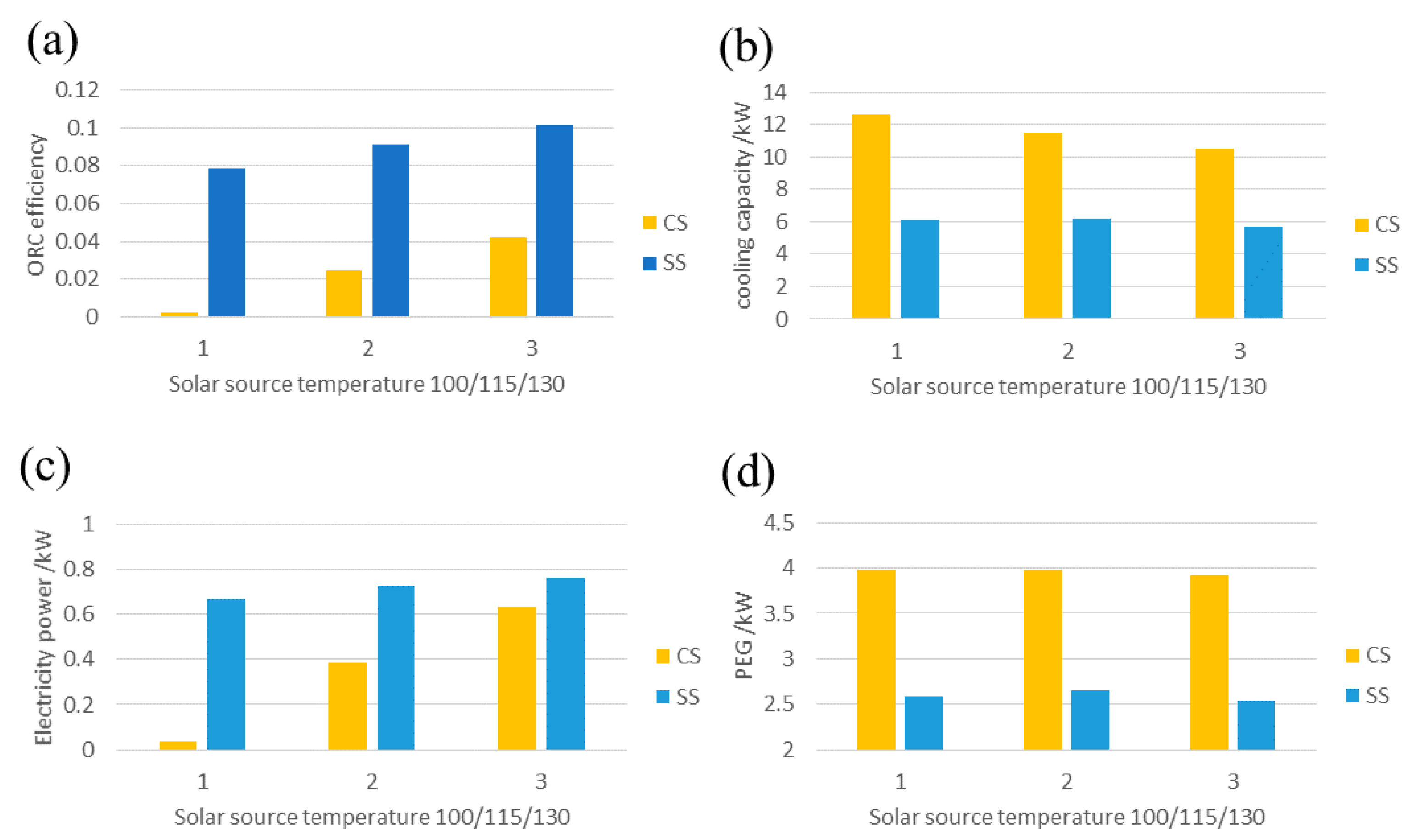
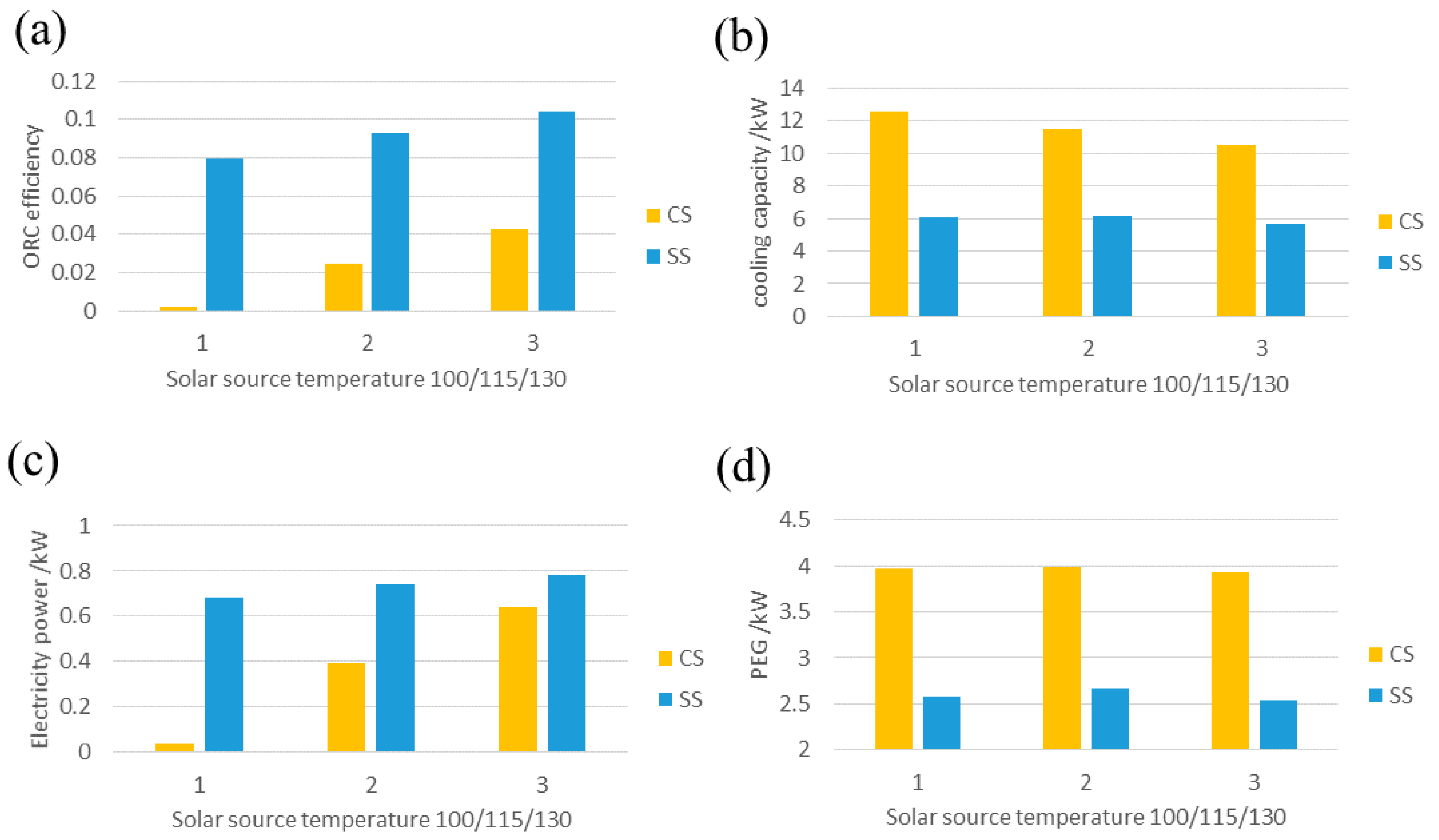
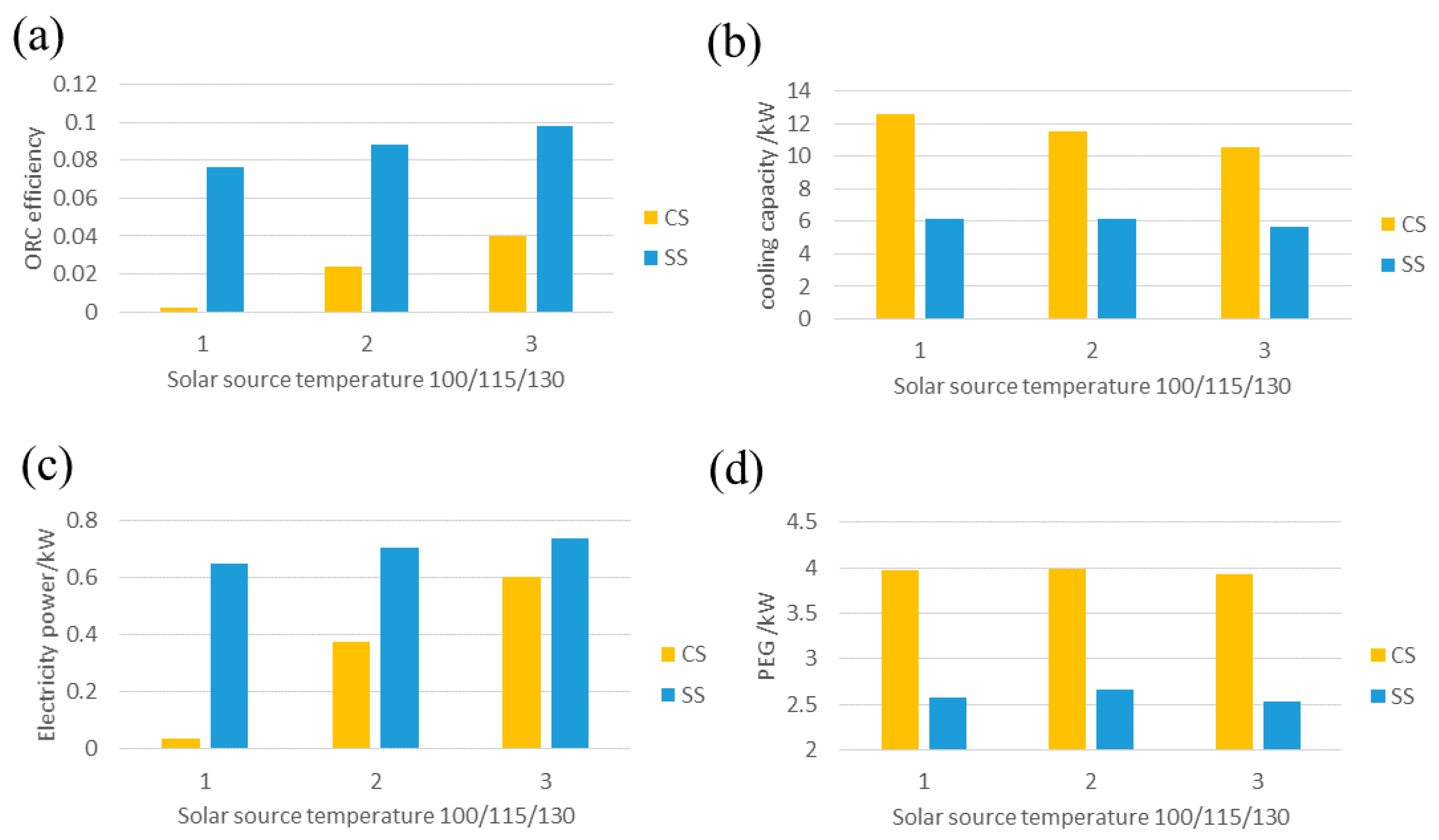
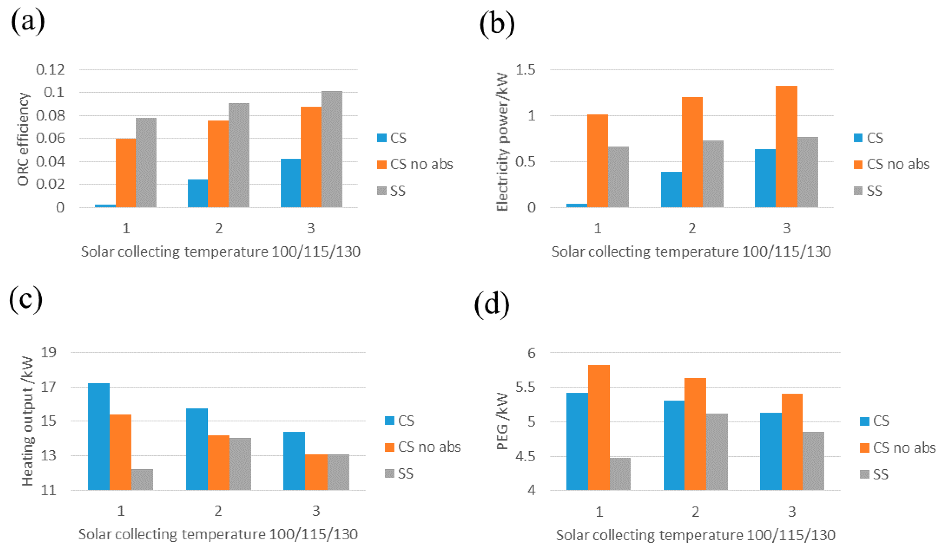
As the hot water demand is relatively small compared with the cooling load for residential buildings in the cooling load dominant regions, the systems would operate for cooling and electricity production in cooling mode. Therefore, useful outputs for this scenario include net electricity production by ORC and cooling production by absorption heat pump. Figure 3, Figure 4 and Figure 5 show the impact of solar collecting temperature on the overall system efficiency, cooling output capacity, electricity generation and primary energy efficiency for the systems with R123, R141b or R1233zd as ORC working fluid. It can be seen that the SS shows the highest ORC efficiency and electricity outputs and this is due to a lower ORC condensing temperature and thus larger pressure difference between evaporator and condenser for shaft work output compared with the CS. The ORC efficiency and electricity output increase with increased solar collecting temperature for both systems. For the CS, the cooling energy efficiency decreases with the increase of the solar collecting temperature, while primary energy efficiency is highest at the solar collecting temperature of 115 °C. The SS shows the highest primary energy efficiency and cooling production at the solar collecting temperature of 115 °C. The system with R141b as ORC working fluid shows best performance for ORC efficiency and primary energy efficiency. Although the driving temperature for absorption cycle is lower and the heat energy amount to drive the ORC is larger, the CS shows higher cooling output and primary energy efficiency, while less electricity output and ORC efficiency. The reason is that all the waste heat from the condenser of ORC is useful for the absorption sub-system though the temperature is relatively low, and the ORC sub-system is more sensible to the temperature difference between the evaporator and condenser.
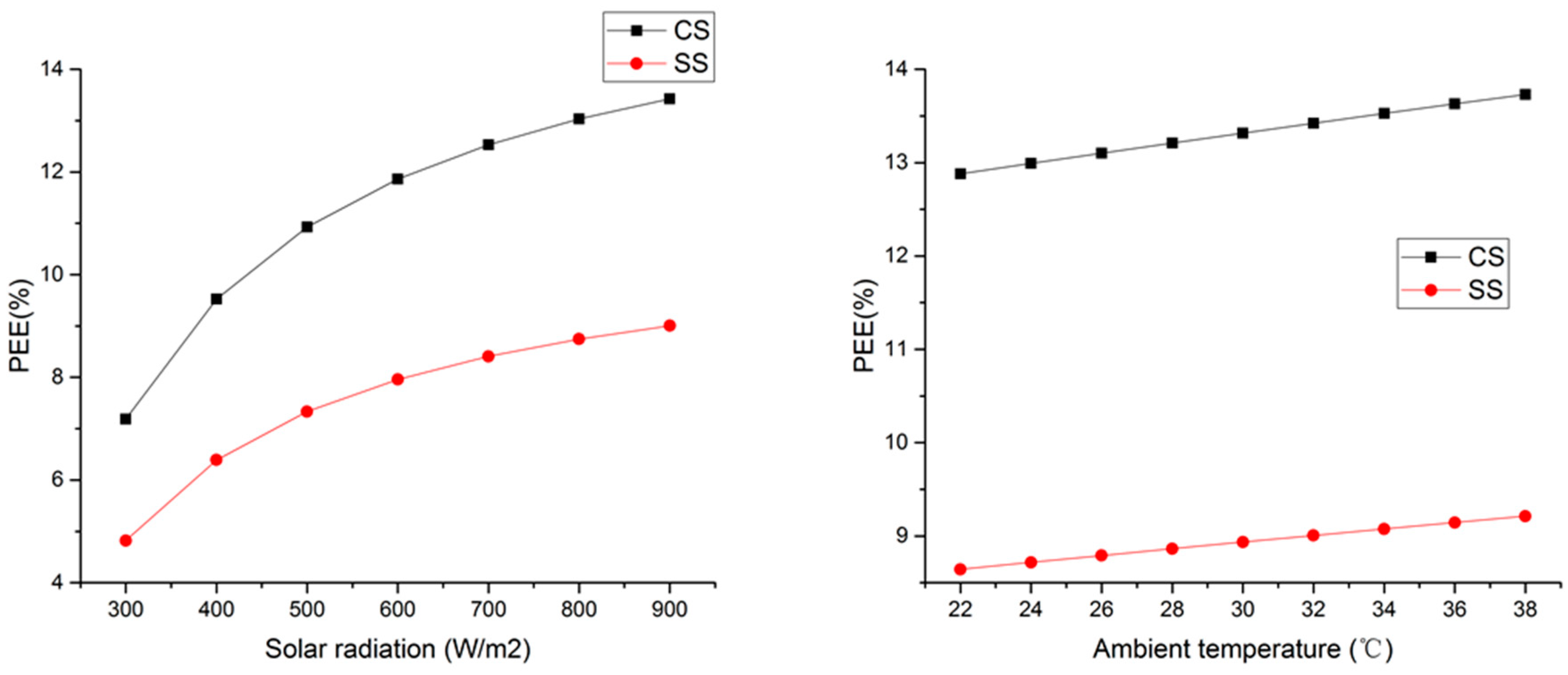
Further, the energy performance of the CS and SS under the designed conditions of solar collecting temperature of 115 °C and R141b as ORC working fluid, under which the systems show highest PEE, was analysed. Varying the solar radiation from 300 to 900W/m2 and the ambient air temperature from 22 to 38 °C while keeping other parameters constant as shown in Table 3, simulation was carried out. The results are shown in Figure 6. It can be found that increasing the solar radiation and ambient temperature both lead to increase in PEE. The PEE of the CS is higher than that of the SS under all conditions.

5.2. Heating Mode

In heating mode, heating and electricity production is considered as the useful energy output for residential applications in the heating load dominant regions. The absorption system operates in heat pump mode, i.e., the generator and evaporator absorb heat source energy from ambient or other waste heat source, while the condenser and absorber reject heat for end users. As the condenser temperature of the ORC sub-system could be higher than heating output temperature, a configuration design without the absorption sub-system is studied in heating mode. The results are shown in Figure 7, Figure 8 and Figure 9. It can be seen that the SS shows higher ORC efficiency at different heat source temperatures. It is due to the higher temperature difference between the heat source and the cold sink, leading to higher ORC efficiency when assuming the efficiency of the turbine and pump is constant. The CS without absorption sub-system (CS no ab) achieves the highest primary energy efficiency and electricity output, while the heating output is not the least. The performance of the systems with R141b as the ORC working fluid is better compared to that with R123 and R1233zd(E). However, it should be noted that R141b is harmful to the environment, with ODP and GWP of 0.12 and 725, respectively. However, the CS without absorption sub-system shows highest primary energy efficiency at the solar collecting temperature of 100 °C, while the SS has the highest primary energy efficiency at a solar collecting temperature of 115 °C. This is because higher collecting temperature results in higher ORC evaporating temperature and more energy loss through the solar collector. Therefore, it has no benefit to further increase the solar collecting temperature.
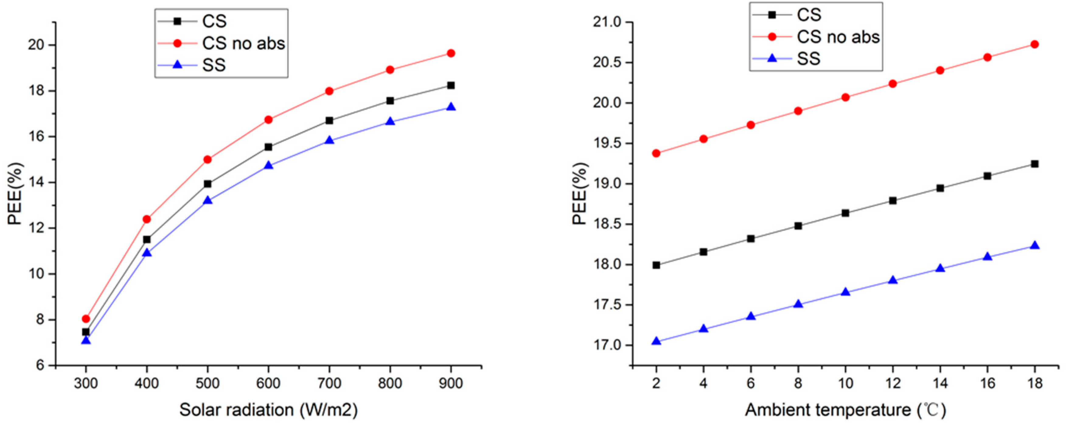
The impact of the environment conditions to the energy performance of the systems was analysed under the designed conditions that yielded highest PPE, i.e., R141b as ORC working fluid, solar collecting temperature of 115 °C for SS while 100 °C for both CS and CS without absorption sub-system. Varying the solar radiation from 300 to 900W/m2 and the ambient air temperature from 2 to 18 °C while keeping other parameters constant as shown in Table 3, simulation was carried out. The results are shown in Figure 10. It can be found that increasing the solar radiation and ambient temperature both lead to increase in PEE. CS without absorption sub-system shows higher PEE than other systems under all conditions. Overall, the CS without the absorption sub-system is preferred for heating mode operation.

6. Conclusions

CS and SS configurations of small-scale CCHP that integrate organic Rankine cycle (ORC) with absorption heat pump are comparatively studied. The system can be designed to generate electricity and cooling output in cooling mode for residential applications in the cooling load dominant regions or electricity and heating output in heating mode for residential applications in heating load dominant regions. In CS, ORC system is set up as a topping sub-system that absorbs all energy rejecting from thermal oil, while absorption system is set up as a bottoming system to generate the cooling output in cooling mode or heating output in heating mode driven by the heat from ORC condenser. In heating mode, the CS without absorption cycle is also studied. In the SS, thermal oil absorbs the solar energy then rejects heat to ORC system and absorption system sequentially, thus ORC system acts as the front sub-system and absorption system acts as the rear sub-system.
A mathematical model, which has been validated with the literature results, was developed to simulate the performance of the integrated systems in cooling and heating mode. It can be concluded that the CS has the highest primary energy efficiency of 13.4% in cooling mode, e, under the solar collecting temperature of 115 °C. And the CS without absorption sub-system shows the highest primary energy efficiency of 19.6% in heating mode, under the solar collecting temperature of 100 °C. The CS has more cooling output while less electricity output in cooling mode than the SS. Increase of the solar collecting temperature results in a slight decrease of the cooling output, while an increase of the electricity output for the CS in cooling mode. In heating mode, the CS without absorption sub-system shows both higher heating and electricity output compared with the SS. Higher solar collecting temperature results in less primary energy efficiency and heating output, as well as more electricity output. Systems with R141b as the ORC working fluid show better performance than others. It should be noted that R141b is harmful to the environment and the highest primary energy efficiency of the system doesn’t stand for the best configuration. The configuration of CS would have to generate electricity and cooling/heating simultaneously, while the SS is more flexible in separate control of thermal and power generation. The configuration selection and control strategy of such technology should be carefully designed to meet the building energy demand.

Author Contributions

Conceptualization, methodology, software, validation, formal analysis, investigation, resources, data curation, visualization, writing—original draft preparation, X.H.; writing—review and editing, project administration, funding acquisition, F.S. All authors have read and agreed to the published version of the manuscript.

Funding

This research was funded by the National Natural Science Foundation of China (No. 51778549), the Natural Science Foundation of Fujian Province of China (No. 2018J05086 and No. 2017J01102) and the Fundamental Research Funds for the Central Universities (No. 20720180065).

Acknowledgments

The authors gratefully acknowledge the financial support of the National Natural Science Foundation of China, the Natural Science Foundation of Fujian Province of China and the Fundamental Research Funds for the Central Universities.

Conflicts of Interest

The authors declare no conflicts of interest.

Nomenclature

Afirst heat loss coefficient of CPC Xvalue
Aaaperture area of solar collector, (m2)Greek
Bsecond heat loss coefficient of CPCηefficiency
COPccoefficient of performance of absorption heat pump for coolingSubscripts
COPc,stcoefficient of performance of standard cooling facilityaabsorption
COPhcoefficient of performance of absorption heat pump for heatingconcondenser
COPh,stcoefficient of performance of standard heating facilitycon,orccondenser of ORC
CPspecific heat capacity(J/kg/K)evaevaporator
CScascade systemeva,orcevaporator of ORC
Gsolar irradiation(W/m2)HEXheat exchanger
hfiheat transfer coefficient(W/m2/K)ggearbox and generator
henthalpy(kJ/mol)genabsorption generator
kconductivity(W/m/K)ooutlet
mmass flow rate (kg/s)iinlet
nnumberppump
PEEprimary energy efficiencytturbine
Qenergy(W)rreceiver, refrigerant
SSseries systemsisentropic
Ttemperature (°C)strstrong solution
ULheat loss coefficient (W/m2/K)uuseful
Wpower work(W)wweak solution

References

  1. Li, J.; Pei, G.; Li, Y.Z.; Wang, D.Y.; Ji, J. Energetic and exergetic investigation of an organic Rankine cycle at different heat source temperatures. Energy 2012, 38, 85–95. [Google Scholar] [CrossRef]
  2. Riffat, S.B.; Zhao, X. A novel hybrid heat-pipe solar collector/CHP system—Part II: Theoretical and experimental investigations. Renew. Energy 2004, 29, 1965–1990. [Google Scholar] [CrossRef]
  3. Goswami, D. Solar thermal power: Status of technologies and opportunities for research. Heat Mass Transf. 1995, 95, 57–60. [Google Scholar]
  4. Martin, C.; Goswami, D.Y. Effectiveness of cooling production with a combined power and cooling thermodynamic cycle. Appl. Therm. Eng. 2006, 26, 576–582. [Google Scholar] [CrossRef]
  5. Zare, V.; Mahmoudi, S.M.S.; Yari, M.; Amidpour, M. Thermoeconomic analysis and optimization of an ammonia–water power/cooling cogeneration cycle. Energy 2012, 47, 271–283. [Google Scholar] [CrossRef]
  6. Mahlia, M.I.T.; Syaheed, H.; Abas, E.P.A.; Kusumo, F.; Shamsuddin, H.A.; Ong, C.H.; Bilad, M.R. Organic Rankine Cycle (ORC) System Applications for Solar Energy: Recent Technological Advances. Energies 2019, 12, 2930. [Google Scholar] [CrossRef] [Green Version]
  7. Cho, H.; Smith, A.D.; Mago, P. Combined cooling, heating and power: A review of performance improvement and optimization. Appl. Energy 2014, 136, 168–185. [Google Scholar] [CrossRef]
  8. Salek, F.; Moghaddam, A.N.; Naserian, M.M. Thermodynamic analysis of diesel engine coupled with ORC and absorption refrigeration cycle. Energy Convers. Manag. 2017, 140, 240–246. [Google Scholar] [CrossRef]
  9. Kanoglu, M.; Dincer, I. Performance assessment of cogeneration plants. Energy Convers. Manag. 2009, 50, 76–81. [Google Scholar] [CrossRef]
  10. Dong, L.; Liu, H.; Riffat, S. Development of small-scale and micro-scale biomass-fuelled CHP systems—A literature review. Appl. Therm. Eng. 2009, 29, 2119–2126. [Google Scholar] [CrossRef] [Green Version]
  11. Alcaide, F.; Cabot, P.-L.; Brillas, E. Fuel cells for chemicals and energy cogeneration. J. Power Sources 2006, 153, 47–60. [Google Scholar] [CrossRef]
  12. Lee, K.H.; Strand, R.K. SOFC cogeneration system for building applications, part 1: Development of SOFC system-level model and the parametric study. Renew. Energy 2009, 34, 2831–2838. [Google Scholar] [CrossRef]
  13. Descombes, G.; Boudigues, S. Modelling of waste heat recovery for combined heat and power applications. Appl. Therm. Eng. 2009, 29, 2610–2616. [Google Scholar] [CrossRef] [Green Version]
  14. Maidment, G.G.; Eames, I.W.; Psaltas, M.; Lalzad, A.; Yiakoumetti, K. Flash-type barometric desalination plant powered by waste heat from electricity power stations in Cyprus. Appl. Energy 2007, 84, 66–77. [Google Scholar] [CrossRef]
  15. Kalinowski, P.; Hwang, Y.; Radermacher, R.; Al Hashimi, S.; Rodgers, P. Application of waste heat powered absorption refrigeration system to the LNG recovery process. Int. J. Refrig. 2009, 32, 687–694. [Google Scholar] [CrossRef]
  16. Al-Sulaiman, F.A.; Dincer, I.; Hamdullahpur, F. Exergy modeling of a new solar driven trigeneration system. Sol. Energy 2011, 85, 2228–2243. [Google Scholar] [CrossRef]
  17. Wang, J.; Dai, Y.; Gao, L.; Ma, S. A new combined cooling, heating and power system driven by solar energy. Renew. Energy 2009, 34, 2780–2788. [Google Scholar] [CrossRef]
  18. Eisavi, B.; Khalilarya, S.; Chitsaz, A.; Rosen, M.A. Thermodynamic analysis of a novel combined cooling, heating and power system driven by solar energy. Appl. Therm. Eng. 2018, 129, 1219–1229. [Google Scholar] [CrossRef]
  19. Settino, J.; Sant, T.; Micallef, C.; Farrugia, M.; Spiteri Staines, C.; Licari, J.; Micallef, A. Overview of solar technologies for electricity, heating and cooling production. Renew. Sustain. Energy Rev. 2018, 90, 892–909. [Google Scholar] [CrossRef]
  20. Zhao, L.; Zhang, Y.; Deng, S.; Ni, J.; Xu, W.; Ma, M.; Lin, S.; Yu, Z. Solar driven ORC-based CCHP: Comparative performance analysis between sequential and parallel system configurations. Appl. Therm. Eng. 2018, 131, 696–706. [Google Scholar] [CrossRef]
  21. Cioccolanti, L.; Hamedani, S.R.; Villarini, M. Environmental and energy assessment of a small-scale solar Organic Rankine Cycle trigeneration system based on Compound Parabolic Collectors. Energy Convers. Manag. 2019, 198, 13. [Google Scholar] [CrossRef]
  22. Bellos, E.; Tzivanidis, C. Investigation of a hybrid ORC driven by waste heat and solar energy. Energy Convers. Manag. 2018, 156, 427–439. [Google Scholar] [CrossRef]
  23. Collings, P.; McKeown, A.; Wang, E.; Yu, Z. Experimental Investigation of a Small-Scale ORC Power Plant Using a Positive Displacement Expander with and without a Regenerator. Energies 2019, 12, 1452. [Google Scholar] [CrossRef] [Green Version]
  24. Boyaghchi, F.A.; Chavoshi, M. Monthly assessments of exergetic, economic and environmental criteria optimization of a solar micro-CCHP based on DORC. Sol. Energy 2018, 166, 351–370. [Google Scholar] [CrossRef]
  25. Tascioni, R.; Cioccolanti, L.; Del Zotto, L.; Habib, E. Numerical Investigation of Pipelines Modeling in Small-Scale Concentrated Solar Combined Heat and Power Plants. Energies 2020, 13, 429. [Google Scholar] [CrossRef] [Green Version]
  26. Kutlu, C.; Erdinc, M.T.; Li, J.; Wang, Y.B.; Su, Y.H. A study on heat storage sizing and flow control for a domestic scale solar-powered organic Rankine cycle-vapour compression refrigeration system. Renew. Energy 2019, 143, 301–312. [Google Scholar] [CrossRef]
  27. Arteconi, A.; Del Zotto, L.; Tascioni, R.; Cioccolanti, L. Modelling system integration of a micro solar Organic Rankine Cycle plant into a residential building. Appl. Energy 2019, 251, 14. [Google Scholar] [CrossRef]
  28. Tian, M.; Su, Y.; Zheng, H.; Pei, G.; Li, G.; Riffat, S. A review on the recent research progress in the compound parabolic concentrator (CPC) for solar energy applications. Renew. Sustain. Energy Rev. 2018, 82, 1272–1296. [Google Scholar] [CrossRef] [Green Version]
  29. Gang, P.; Jing, L.; Jie, J. Design and analysis of a novel low-temperature solar thermal electric system with two-stage collectors and heat storage units. Renew. Energy 2011, 36, 2324–2333. [Google Scholar] [CrossRef]
  30. Zheng, Z.; Johnston, A.M.; Fletcher, D.F.; Haynes, B.S. Heat exchanger specification: Coupling design and surface performance evaluation. Chem. Eng. Res. Des. 2015, 93, 392–401. [Google Scholar] [CrossRef]
  31. Turns, S.R. Thermodynamics: Concepts and Applications; Cambridge University Press: Cambridge, UK, 2006. [Google Scholar]
  32. Herold, K.E.; Radermacher, R.; Klein, S.A. Absorption Chillers and Heat Pumps; CRC Press: Boca Raton, FL, USA, 2016. [Google Scholar]
  33. JGJ 75-2012. Design Standard for Energy Efficiency of Residential Buildings in Hot Summer and Warm Winter Zone; China Architecture & Building Press: Beijing, China, 2013. (In Chinese) [Google Scholar]
  34. Lemmon, E.W.; Huber, M.L.; Mclinden, M.O. NIST Standard Reference Database 23: Reference Fluid Thermodynamic and Transport Properties-REFPROP, Version 9.1; NIST NSRDS; NIST: Gaithersburg, MD, USA, 2013.
  35. Bellos, E.; Tzivanidis, C. Parametric analysis and optimization of a solar driven trigeneration system based on ORC and absorption heat pump. J. Clean. Prod. 2017, 161, 493–509. [Google Scholar] [CrossRef]
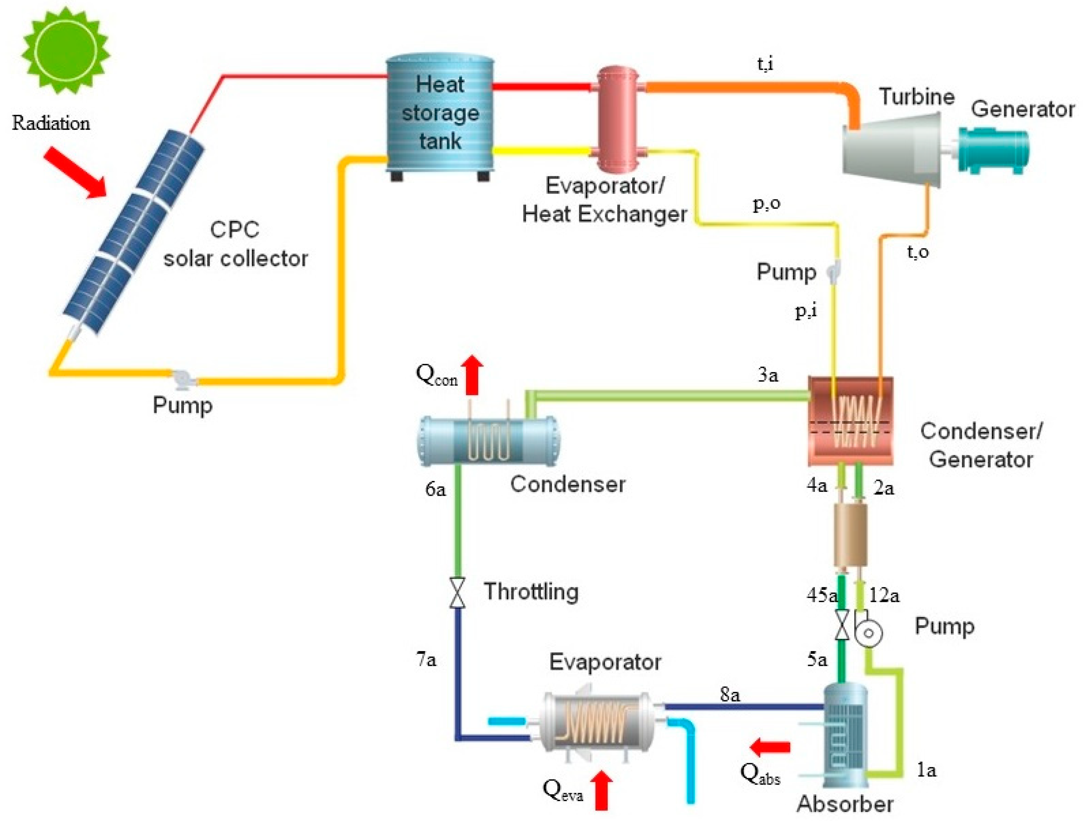
Figure 1. Schematic diagram of the cascade system (CS) for solar combined cooling, heating and power generation.
Energies 13 00946 g001
Figure 2. Schematic diagram of the series system (SS) for solar combined cooling, heating and power generation.
Energies 13 00946 g002
Figure 3. (a) ORC efficiency, (b) cooling output capacity, (c) electricity generation and (d) primary energy efficiency for the combined cooling, heating and power (CCHP) systems under different solar collecting temperature with R123 as ORC working fluids in cooling mode.
Energies 13 00946 g003
Figure 4. (a) ORC efficiency, (b) cooling output capacity, (c) electricity generation and (d) primary energy efficiency for the CCHP systems under different solar collecting temperature with R141b as ORC working fluids in cooling mode.
Energies 13 00946 g004
Figure 5. (a) ORC efficiency, (b) cooling output capacity, (c) electricity generation and (d) primary energy efficiency for the CCHP systems under different solar collecting temperature with R1233zd as ORC working fluids in cooling mode.
Energies 13 00946 g005
Figure 6. PEE of the systems as a function of solar radiation and ambient temperature.
Energies 13 00946 g006
Figure 7. (a) ORC efficiency, (b) cooling output capacity, (c) electricity generation and (d) primary energy efficiency for the CCHP systems under different solar collecting temperature with R123 as ORC working fluids in heating mode.
Energies 13 00946 g007
Figure 8. (a) ORC efficiency, (b) cooling output capacity, (c) electricity generation and (d) primary energy efficiency for the CCHP systems under different solar collecting temperature with R141b as ORC working fluids in heating mode.
Energies 13 00946 g008
Figure 9. (a) ORC efficiency, (b) cooling output capacity, (c) electricity generation and (d) primary energy efficiency for the CCHP systems under different solar collecting temperature with R1233zd as ORC working fluids in heating mode.
Energies 13 00946 g009
Figure 10. PEE of the systems as a function of solar radiation and ambient temperature.
Energies 13 00946 g010
Table 1. Model validation for organic Rankine cycle (ORC).
Operating CasePressure of Condenser
/kPa
Pressure of Evaporator
/kPa
Evaporating Temperature/°CSuperheating Temperature
/°C
Efficiency of Ref [1]Efficiency of Present WorkDeviation
Case 1 90.2610.288.9710.528.2%8.21%0.12%
Case 283497.880.659.057.7%7.7%0%
Case 373.1414.873.535.867.4%7.39%0.14%
Table 2. Model validation for absorption heat pump.
TE (°C)TG (°C)TC (°C)TA (°C)COP of Ref [25]COP of Present WorkDeviation
47031310.7990.7960.4%
46931350.6750.6831.1%
56628350.7630.7600.4%
67233370.7150.7190.5%
86325370.8320.8171.8%
88546390.5740.5770.6%
96628340.8530.8441.1%
Table 3. System parameters and operating conditions for the simulation.
ParametersValueUnit
Collector With 2.5m
Collector Length14m
Solar system working fluidTherminol 66
Volume of the thermo oil storage tank2m3
ORC system2.5kW
ORC working fluidR123/R141b/R1233zd
ORC superheating temperature10°C
Pressure drop through ORC pipe40kPa
Turbine isentropic efficiency 80%
Generator efficiency70%
Pump efficiency70%
Cooling capacity of absorption heat pump11kW
Evaporator temperature of absorption chiller4°C
Condenser temperature of absorption chiller34°C
Absorber temperature of absorption chiller34°C
Condenser temperature of absorption heat pump37°C
Absorber temperature of absorption heat pump37°C
Solar radiation900W/m2
Ambient temperature for cooling mode32°C
Ambient temperature for heating mode5°C