Article

Experimental and CFD Analysis of Impact of Surface Roughness on Hydrodynamic Performance of a Darrieus Hydro (DH) Turbine

by
Mohammad Hassan Khanjanpour
and
Akbar A. Javadi
*
Department of Engineering, University of Exeter, Exeter EX4 4QF, UK
*
Author to whom correspondence should be addressed.
Energies 2020, 13(4), 928; https://doi.org/10.3390/en13040928
Submission received: 17 January 2020 / Revised: 10 February 2020 / Accepted: 14 February 2020 / Published: 19 February 2020
(This article belongs to the Section A3: Wind, Wave and Tidal Energy)

Abstract

:
Although improving the hydrodynamic performance is a key objective in the design of ocean-powered devices, there are some factors that affect the efficiency of the device during its operation. In this study, the impacts of a wide range of surface roughness as a tribological parameter on stream flow around a hydro turbine and its power loss are studied. A comprehensive program of 3D Computational Fluid Dynamics (CFD) modeling, as well as an expansive range of experiments were carried out on a Darrieus Hydro (DH) turbine in order to measure reduction in hydrodynamic performance due to surface roughness. The results show that surface roughness of turbine blades plays an important role in the hydrodynamics of the flow around the turbine. The surface roughness increases turbulence and decreases the active fluid energy that is required for rotating the turbine, thereby reducing the performance of the turbine. The extent of the negative impact of surface roughness on the drag coefficient, pressure coefficient, torque, and output power is evaluated. It is shown that the drag coefficient of a turbine with roughness height of 1000 μm is about 20% higher than a smooth blade (zero roughness height) and the maximum percentage of reduction of output power could be up to 27% (numerically) and 22% (experimentally).

1. Introduction

Recently, due to the increase in price of energy produced from fossil fuels, as well as their harmful effects on the environment, there has been a growing interest in renewable energy, for instance from ocean power, wind, biomass, geothermal, and solar. These sources of sustainable energy have enormous potential for providing the energy required by humans [1]. Among the above options, oceans and seas provide a renewable resource with the advantage of being predictable many days in advance, stable during day and night, and significantly greater in energy density compared to wind and solar energies [2]. This clean energy can be used either directly for electricity generation [3] or/and for seawater desalination [4]. Ocean power can be divided into two major forms: Wave power and tidal power [5]. Tidal energy takes advantage of the natural ebb and current of marine tidal waters induced mainly by the interaction of earth, sun, and moon gravity fields [6]. Tidal convertors can be utilized for converting the kinetic energy of water to mechanical energy of shafts, similar to wind turbines [7]. Several turbines have been developed that can use hydrodynamic lift effectively [8,9,10,11,12,13]. In particular, a special design suggested by French engineer Georges J. Darrieus [14] in 1925 has been regarded as a promising idea for contemporary wind turbines. The main benefits of Darrieus turbines are (i) their design is relatively easy, (ii) their different parts can be adjusted at ground level, and (iii) they do not need a yaw system which is an auxiliary part of the wind turbine for orientation [15]. Attempts have been made, particularly in the UK, the US, and Germany, to develop this design for efficient wind turbines [16]. Japanese researchers were pioneers in using the Darrieus type turbine as tidal convertors (DH turbine) [17]. Parametric analysis of Darrieus turbines is necessary to find the best way to reduce the cost of manufacturing, as well as their maintenance.
One obvious weakness of tidal turbine is the price of manufacturing. These turbines were required to be submerged in the seawater which is quite costly, thus there have been attempts by designers to reduce the price of the turbine [18]. Nevertheless, there should be a trade-off between reducing the price and improving or maintaining the performance of the turbine. Solid particles, marine animals, and cavitation erosion [19] could increase the surface roughness of blades which could affect turbine’s efficiency. As the surface roughness of turbine increases, its power output greatly decreases [20]. Maruzewski et al. [21] carried out experimental and numerical investigation into the impacts of surface roughness on the performance of Francis Hydro (FH) turbine. According to their report, in a severe case of roughness, the performance could decrease to 15%. Although, this work provided valuable data for FH turbine, because of its configuration, the results cannot be generalized for DH turbine. Walker et al. [21] studied the effects of blade roughness on the performance of a two-blade horizontal hydro turbine experimentally and numerically. Their results showed about 18% reduction in output power with roughness height (Hr( of 625 μm. However, horizontal axis turbines are also different in shape and performance compared with DH turbines. Recently, Priegue and Stoesser [22] carried out an experimental study to investigate the effects of surface roughness on the performance of a vertical hydro turbine. They reported negative effect of blade roughness on the performance of the tidal turbine. Although this research is another useful contribution in this field, it was limited to an experimental work involving only three different roughness values and they did not study the physics of the flow around the turbine.
A review of the literature shows that there is a gap in detailed understanding of the effects of surface roughness on the performance of hydro turbines. In this work, a comprehensive CFD simulation and a number of laboratory experiments were carried out, covering a wide range of roughness values for a vertical hydro turbine, in order to quantify the impacts of roughness on the hydrodynamic performance of hydro turbines. The main goal of this research is to study the adverse effects of roughness on a DH turbine both numerically and experimentally. In the following sections the results of the numerical and experimental models are presented and discussed.

2. Numerical Modeling

2.1. Model Geometry

Some key parameters of DH turbine are presented in Table 1. In previous literature reports [23,24,25] NACA 0015 airfoil has been proposed for turbines. Therefore, in the current study NACA 0015 is selected for the experiments and numerical simulations. The water velocity was set at 1.0 m/s and height of blade and length of chord were selected as 0.45 and 0.3 m, respectively.
Figure 1 shows a CAD design of a three-blade DH turbine subject to a horizontal flow of water. The interaction of DH turbine with water is complex and various parameters are needed for their complete analysis.
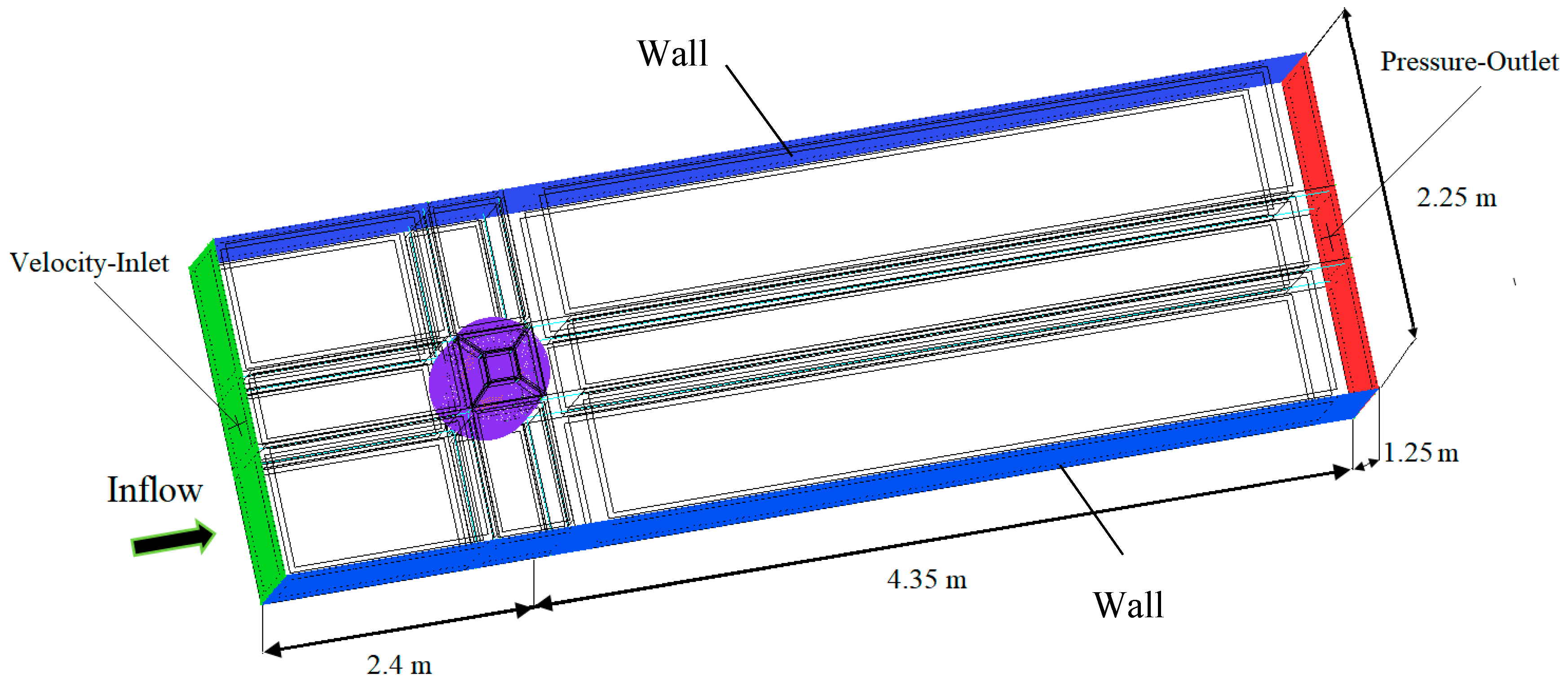
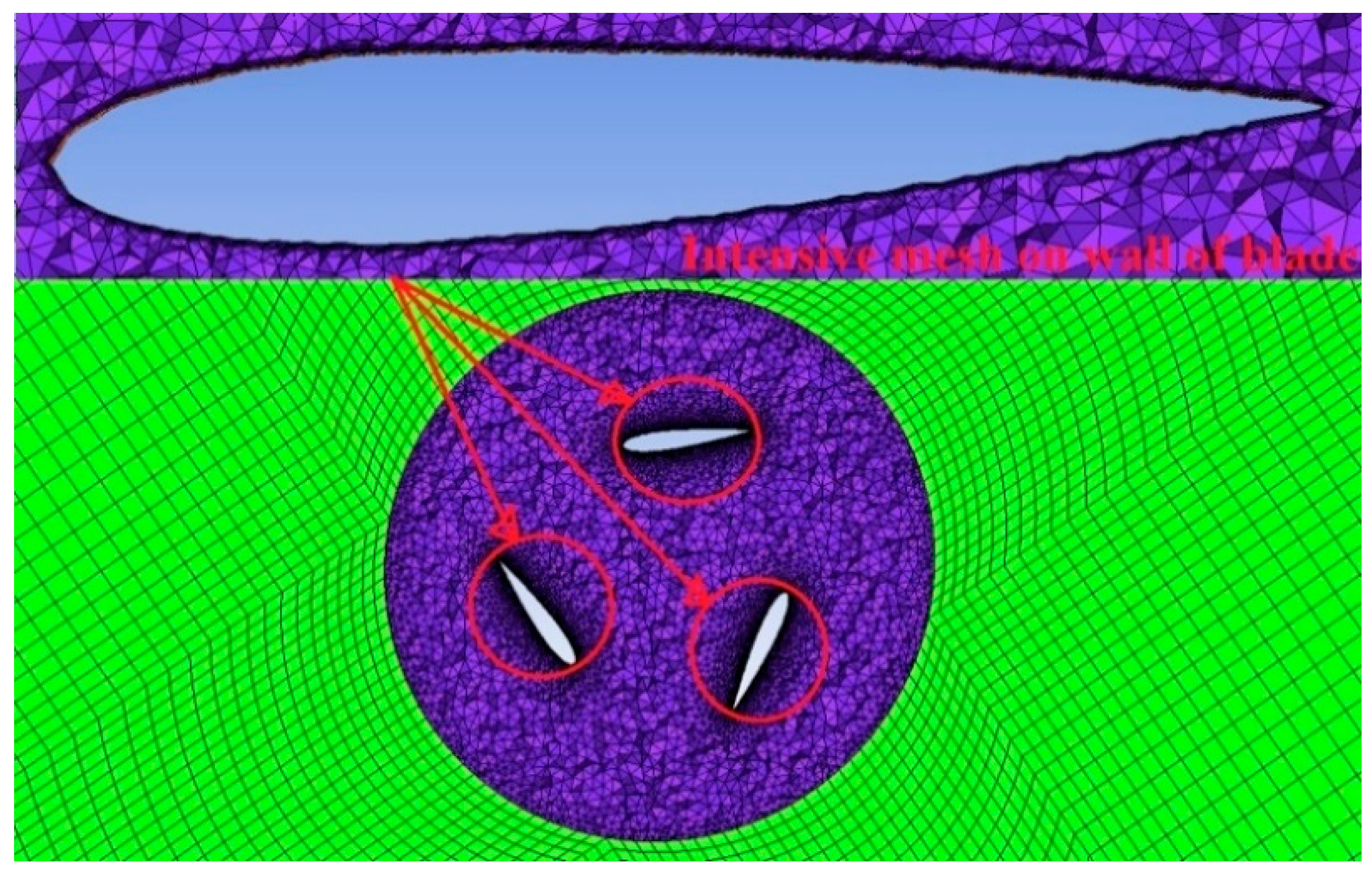
The selection of a suitable computational domain is a key factor for the CFD model to be representative of the reality [26]. The domain should be optimized in order to reduce the time of computational runs and also provide enough space for appropriate meshing. Furthermore, the CFD domain should be suitable for reproducing DH turbine rotation without the effects of the walls. The domain sizes were selected based on Navabi’s [27] analysis of the domain size independence. To analyze the performance of the turbine, a 3D transient time-accurate and dynamic mesh CFD model was developed using the ANSYS Fluent 19 code. The geometry of the domain used is shown in Figure 2. Designing of the geometry was done in the SOLIDWORKS software. Mesh generation was done in the ANSYS ICEM CFD software. Figure 3 shows a circular domain and intensive mesh on the wall of the NACA 0015 airfoil. The distances between the centre of the turbine blades and the input and output of the domain are 2.4 and 4.35 m, respectively, and the distance between the blades and the upper and lower levels is 0.90 m. The height of the turbine blades is 0.45 m. An unstructured mesh was created around the blades while a structured mesh was used for the rest of the domain. The total number of cells in this simulation was 1,249,795 (after grid sensitivity study). The k-ω (SST) (Shear Stress Transport) turbulence model was used to simulate the problem, and the coupling of the speed and pressure equations was performed with the PISO (Pressure-Implicit with Splitting of Operators) algorithm [28]. Water velocity at the entrance was 1 m/s. For the entry, the velocity inlet and for the exit the pressure outlet were used as boundary conditions. The bottom, top, and side boundaries of the domain were specified as the wall boundary condition. The simulation was done as transient, and the time step selected (after time dependence test) was 0.0001s.

2.2. Grid Sensitivity (GS) Test

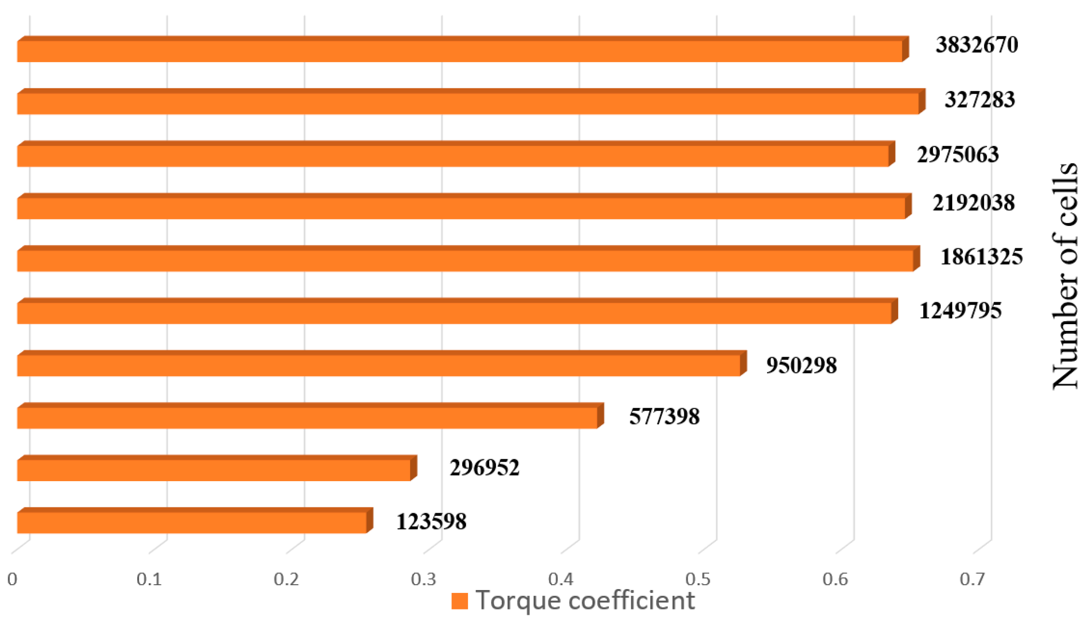
A Grid Sensitivity (GS) test was carried out by generating ten different meshes for the DH turbine with NACA 0015 airfoil. The results of the GS test as the variation of average torque coefficient (Cm) with the number of cells are presented in Figure 4. The number of cells was increased uniformly from 123,598 cells to 3,832,670 whilst y+ (nondimentional wall distance) was 1 [29] in all the tested meshes. Since the turbine’s torque is not constant, the mean output torque was used to calculate the mean Cm. By using Equations (1) and (2) [30], the average torque coefficient of each case with different number of cells was calculated (Figure 4).
The results showed that beyond 1,249,795 cells, the relative standard deviation (RSD) of Cm is about 1.3%. Since the computational cost of CFD analysis increases rapidly with the number of cells and RSD ≈ 1.3% was considered acceptable for similar works on Darrieus turbines (e.g., [8]), 1,249,795 cells were chosen for numerical analysis.
T m = 1 n i = 1 n T i
C m = T m 1 2 ρ A U w 3
where Tm: Average torque; Ti: Torque; Cm: Average torque coefficient; ρ : Density of water; Uw: velocity of water, A: Area of the blades; n: Number of data points.

2.3. Time Sensitivity (TS) Test

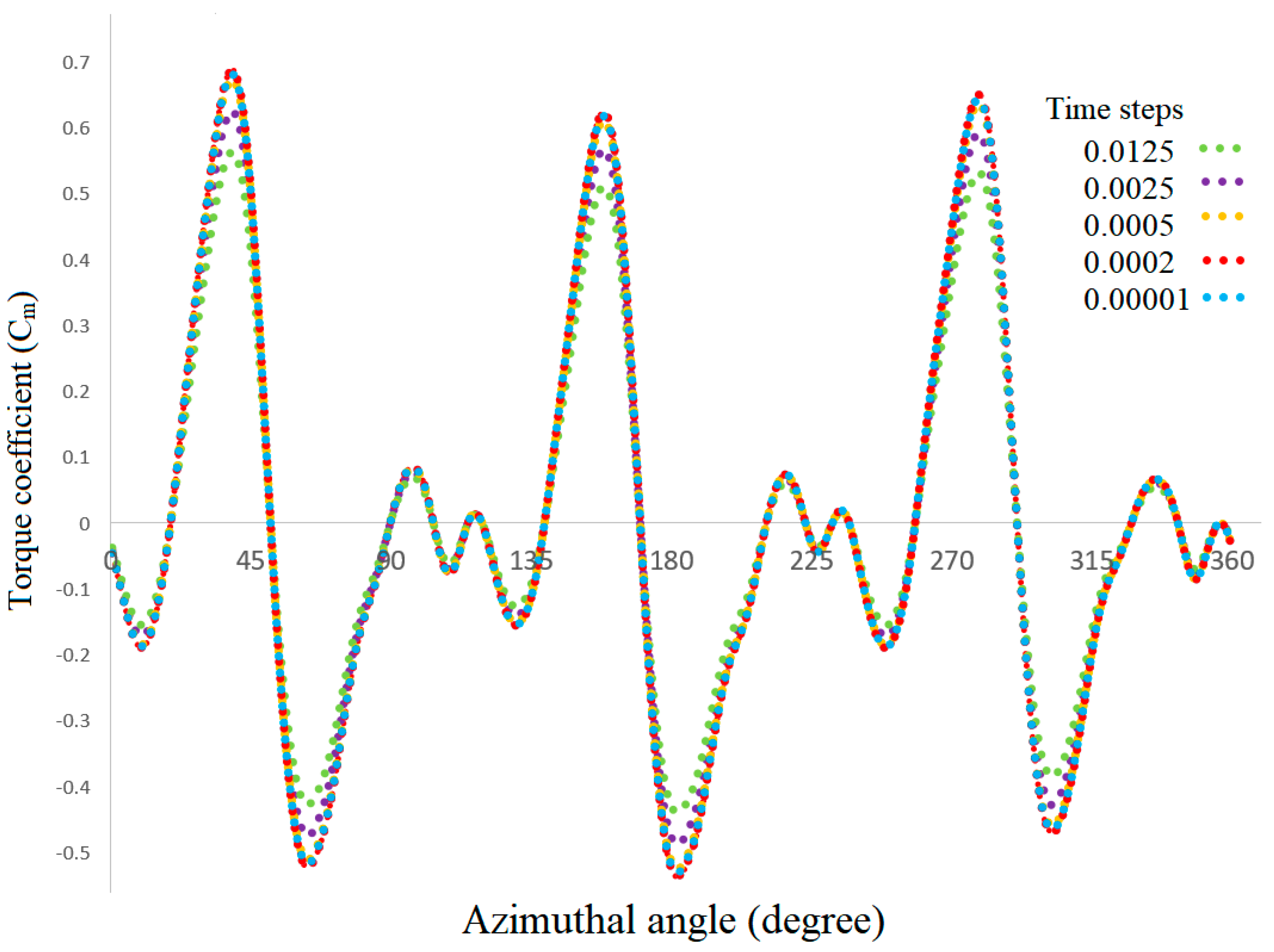
Time step is amongst the most important factors in unsteady simulations. It should be small enough to guarantee temporally independent results [31]. In order to understand the sensitivity of the solution to time step, a subsequent study at the tip speed ratio of ζ = 1.5 and water velocity of Uw = 1 m/s was carried out. To obtain a successful convergence in the final results, the time step used for each simulation must be carefully selected [32]. In the TS test, we seek to use a large time step that assures the minimum computational time without losing accuracy of the results. Five different simulations with time steps of Δt = 0.0125, Δt = 0.0025, Δt = 0.0005, Δt = 0.0002, and Δt = 0.00008 were carried out to determine how the time step affects the torque of DH turbine with NACA 0015 airfoil. For these different time steps, the variations of torque with azimuthal angle are plotted in Figure 5. The results show that, among the five different time step sizes, there is little difference in torque coefficient between Δt = 0.0005 and Δt = 0.00008. Therefore, a time step of 0.0005 was chosen for the rest of the CFD simulations in order to reduce computational time to a minimum.

3. Experimental Setup

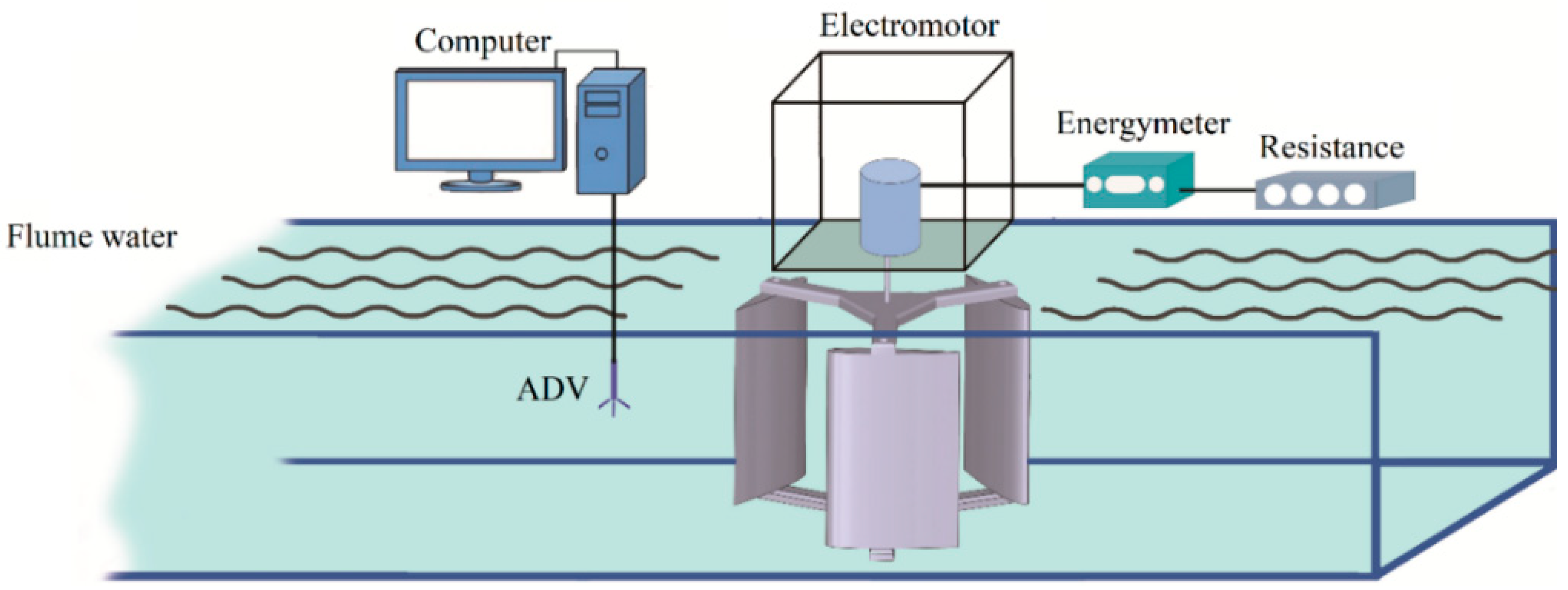
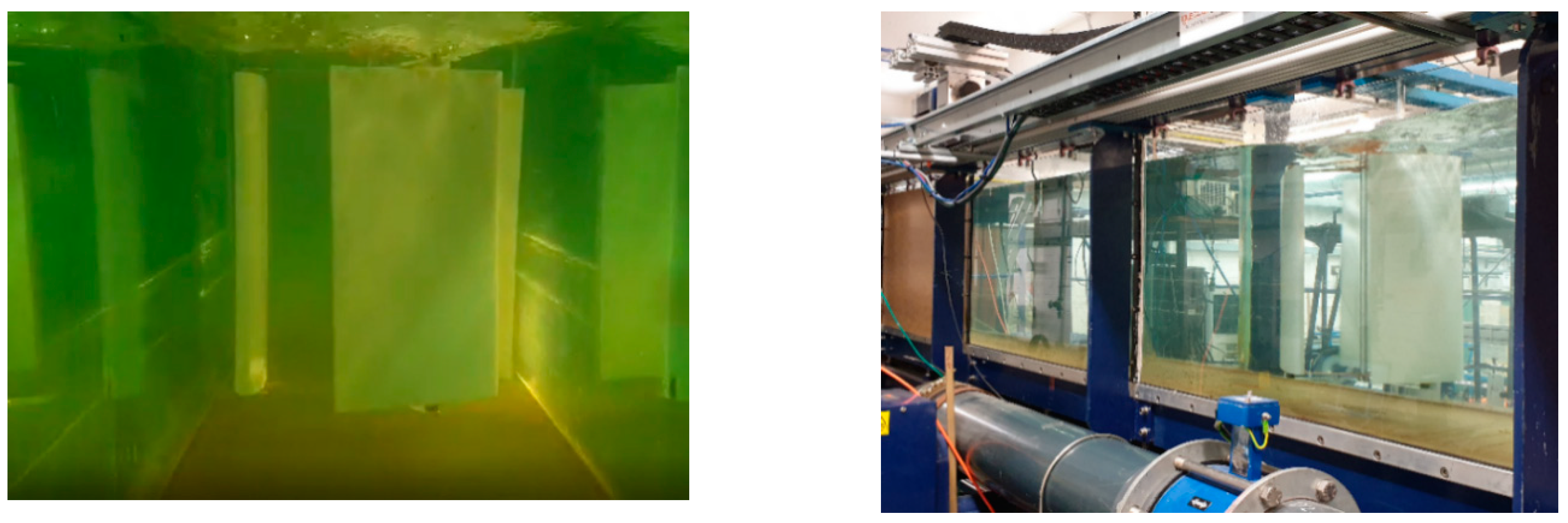
An experimental setup was designed and prepared for measuring output power of the DH turbine (Figure 6). A three-blade DH turbine was made from Perspex with 3D printing at the Mechanical Workshop of the University of Exeter, using a NACA 0015 airfoil profile with a chord length of 300 mm. The manufactured DH turbine was submerged in a flume (see Figure 7) in order to measure the output energy of the turbine. An SEP energy meter, a resistance box, and a small electromotor were employed to measure the power output of the DH turbine. The accuracy of the energy meter is approximately ±1% for voltage and current. Moreover, an Acoustic Doppler Velocimeter (ADV) NORTEK AS was used to measure the characteristics of the upstream flow of the flume.
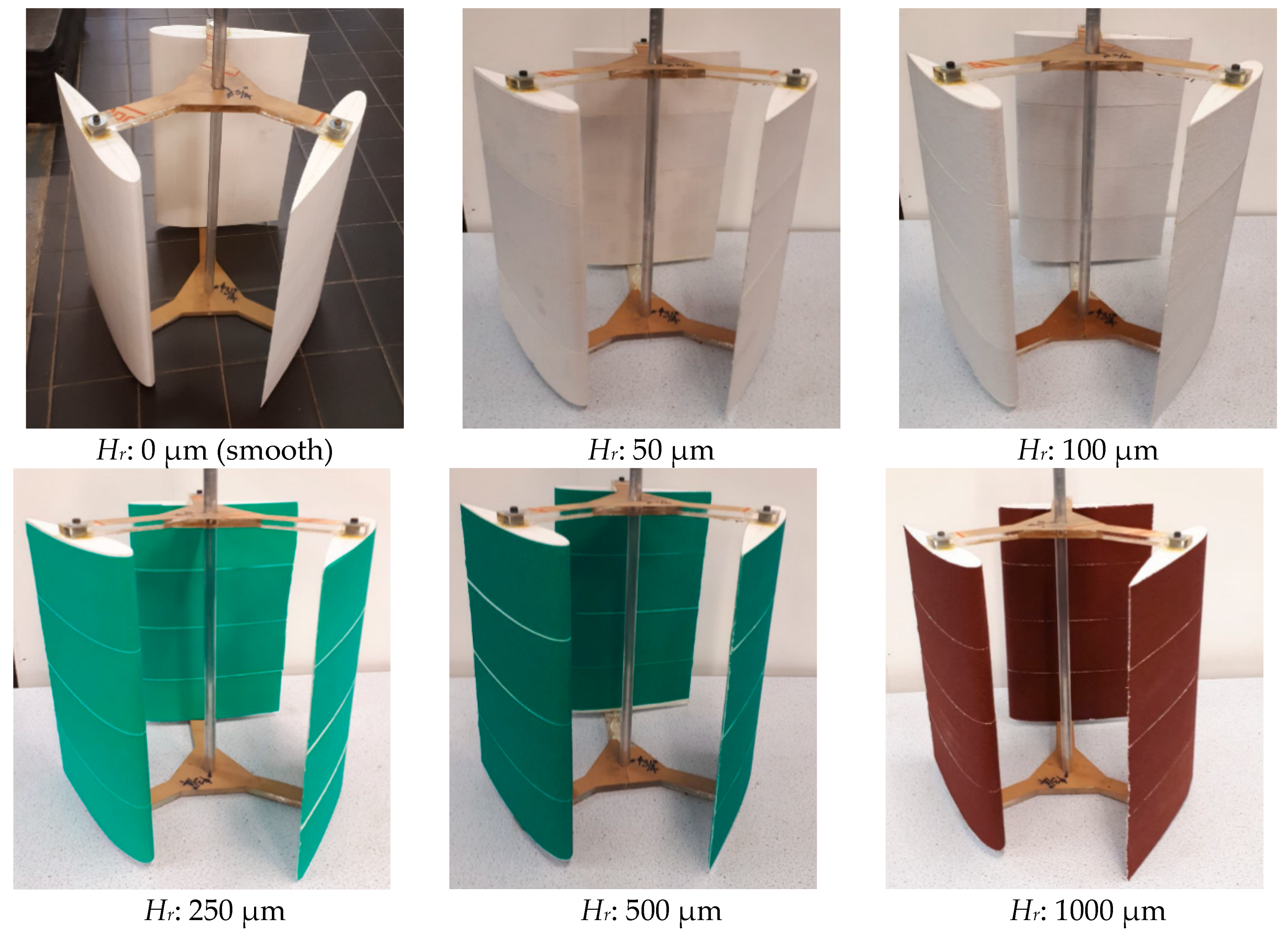
A comprehensive set of laboratory experiments was designed and carried out to measure energy losses due to surface roughness. Rolled waterproof sandpapers with uniform roughness were used in the experiments. Five different sandpapers with roughness values of 50, 100, 250, 500, and 1000 μm were used to study the effects of surface roughness on the flow and energy output. The experimental results will be presented and compared with the CFD results in the following sections.

4. Validation of the CFD Model

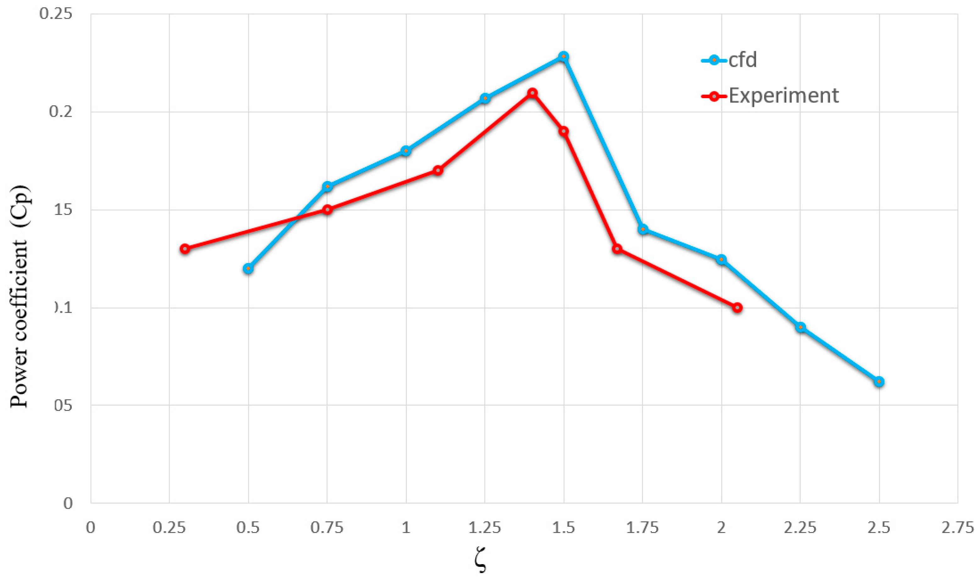
In this section, the experimental results and outcomes from some other studies from literature will be compared with the results of the CFD simulations of the DH turbine to examine the validity of the CFD model. For this purpose, Power Coefficient (Cp) was calculated at different tip speed ratios (ζ) both experimentally and computationally. The power coefficient can be calculated as [33]:
C p = P o 1 2 ρ A U w 3
where Cp: Power coefficient; Po: Output power.
Moreover, Tip Speed Ratio (ζ) can be calculated as [34]:
ζ = ω R U w
where ω : Angular velocity of turbine; R: Radius of turbine’s hub.
The calculated values of Cp at different values of ζ are plotted in Figure 8. It can be seen that the numerical results are in good agreement with the experimental results. The general trend of the present experimental and CFD results is also consistent with some results reported in the literature [34,35] on the performance of three-blade NACA type DH turbines.

5. Modeling of Roughness Based on Modified Law of the Wall

The k-ω SST turbulent model [35] focuses on the precision of the k-ω model in the areas close to the wall. The k-ω (SST) model’s transport equations which are used in the Fluent code are as follow [36]:
t ( ρ k ) + x i ( ρ k u i ) = x j [ L k k x j ] + A k B k
t ( ρ ω ) + x i ( ρ ω u i ) = x j [ L ω ω x j ] + A ω B ω + C ω
where ui: Mean velocity; Ak: The production terms of k; Bk: Production terms of k; Aω: The production terms of ω; Bk: Dissipation terms of k; Bω: Dissipation terms of ω; LK: The effective diffusivity of k; Lω: The effective diffusivity of ω; and Cω: The diffusion term.
For modeling surface roughness, the rough wall model is available in ANSYS Fluent [37] which was adapted from Sommerfeld and Huber’s work [38]. To implement surface roughness in ANSYS Fluent, the Roughness Height (Hr) and the Roughness Constant (C) should be defined [39]. These two parameters are explained here. The effects of surface roughness can be properly accounted for in CFD codes by modified wall law as follows [40]:
U q u 1 τ w / ρ = 1 k 1 ln [ 9.793 u 1 y q μ ] Δ G
where Uq: Velocity at the wall near the cell at centre point q; yq: Height at the centre point q of the cells near the wall; µ: Viscosity; ΔG: Roughness function; τw: Wall shear stress; k1: Karman constant; and u1: The wall friction velocity which can be defined as [41]:
u 1 = 0.55 k q 0.5
where kq is the turbulent kinetic energy near the wall at point q of the cell. According to Cebeci et al., ΔG for fully rough regime can be defined as [42]:
Δ G = 1 κ ln ( 1 + C H s + )
where Hs+: nondimentional roughness height, and C: Roughness constant.
The range of roughness constant is 0–1 and according to Ming-gao et al. [43], who worked on impacts of roughness on the numerical centrifugal pumps using Fluent, the roughness constant has a small effect on the numerical prediction of centrifugal pump performance. In this work, the value of C is taken as 0.5. Moreover, the nondimensional roughness height is defined as:
H s + = ρ u 1 H r μ

6. Results and Discussion

6.1. Numerical Results

6.1.1. Effects of Surface Roughness on Flow Pattern

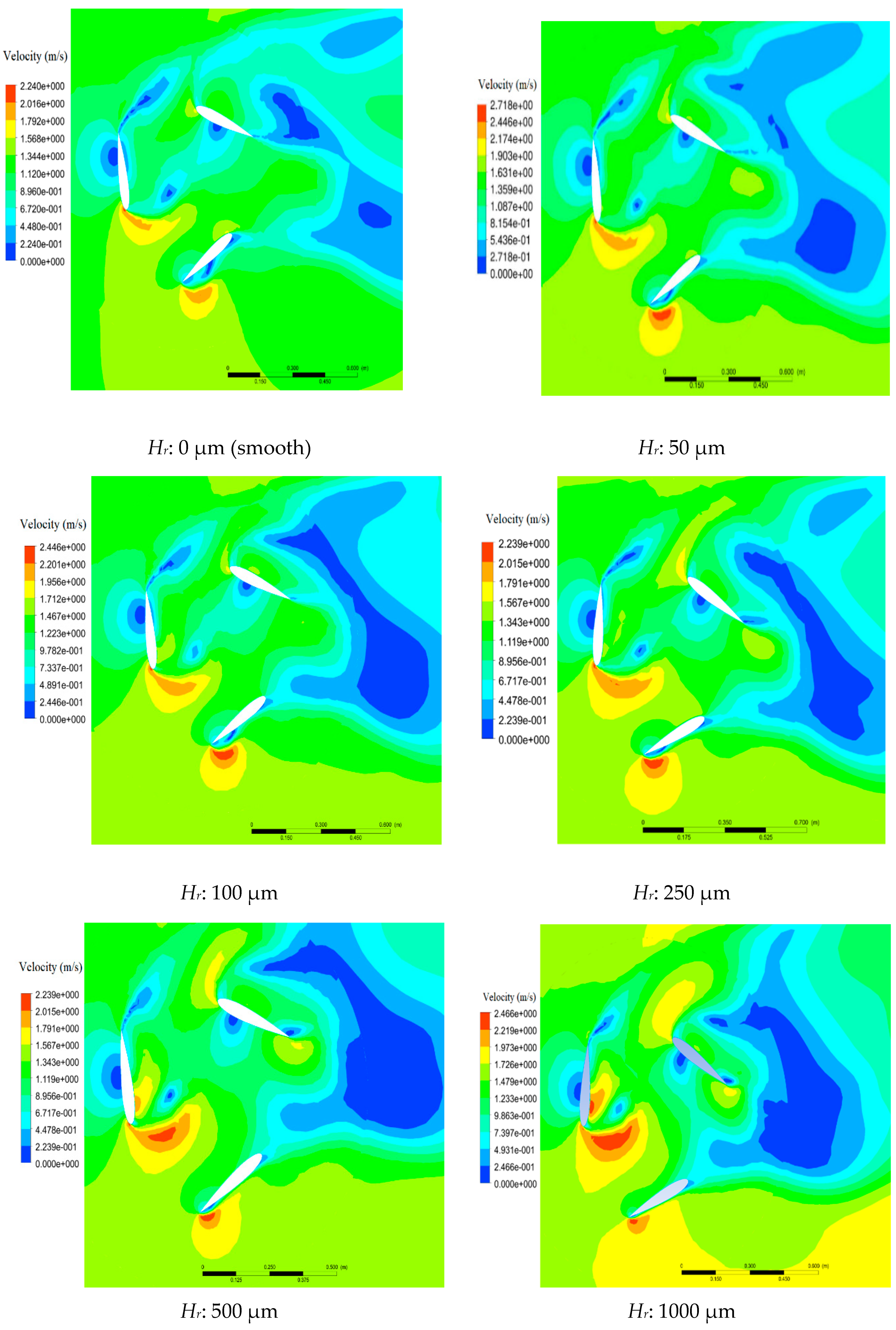
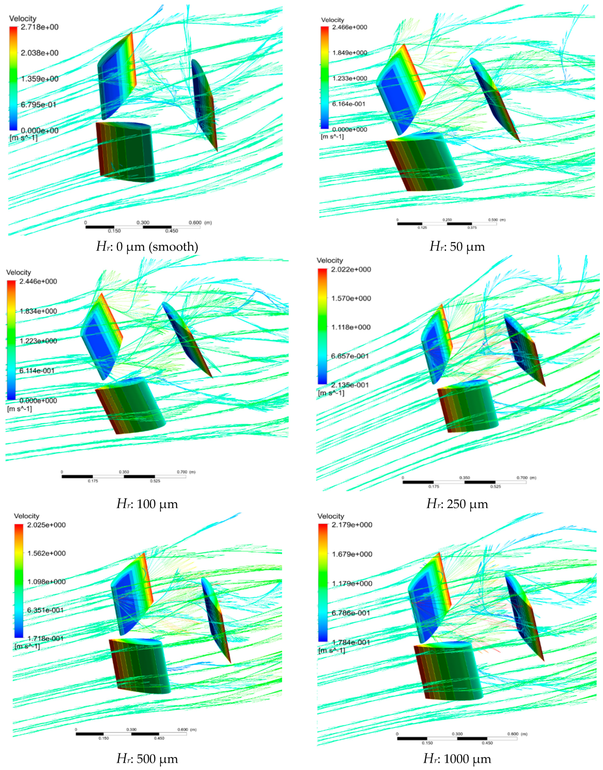
The DH turbine with NACA 0015 airfoil was simulated using the CFD model in six different average roughness heights (Hr) of 0, 50, 100, 250, 500, and 1000 μm at ζ = 1.5. One of the most important factors for simulation of roughness is that the turbulence model should be proven and validated. The k-ω (SST) model was used as the turbulence model, the capabilities of which have been verified the by Sagol et al. [44] and Villalpand et al. [45] for impacts of roughness. To analyze and understand the phenomenon of flow across a structure such as DH turbine, the distribution of velocity and velocity vectors can be useful. The data obtained from the 3D CFD analysis are presented in Figure 9, Figure 10, Figure 11 and Figure 12. To better understand the effect of roughness height on the flow, the velocity distribution is presented in a cross-section (Figure 9) and the velocity vectors are shown in 3D (Figure 10). In order to obtain a comparison between the turbines with different roughness heights, we select a reference angle (180°) in the 6DOF (dynamic mesh) and then the turbine setup is simulated with different roughness heights. By using the CFD Post software at an angle of 60° related to the chosen reference, the velocity contours in a given plane and the velocity vectors are obtained in Figure 9 and Figure 10, respectively. It can be seen that the turbines with various surface roughness heights can make turbulence in the stream flow. This turbulence is not like passing fluid through the body of an airplane or an airfoil. The perturbations of all three blades accumulate and interact and cause the stream flow to change. Fluid turbulence always reduces the kinetic energy, which in turn, reduces the total turbine efficiency. It can be seen that at lower roughness heights (less than 100 μm) the hydraulic effects of roughness are negligible (see Figure 9 and Figure 10). At high roughness, the velocity vectors of the fluid flow have a significant leap and this has a significant effect on the fluid flow (especially for roughness heights greater than 500 μm). This effect will be discussed and quantified numerically in the following sections.

6.1.2. Effects of Surface Roughness on Pressure Coefficient (Kp) and Drag Coefficient (Cd)

The performance of a tidal turbine is very sensitive to the pressure and drag coefficients of the specific hydrofoil section used [20]. The pressure coefficient is defined as [46]:
P P w 1 2 ρ A U w 2
where Kp: Pressure coefficient; P: Pressure; A: Area of the blades; Pw: Pressure of water.
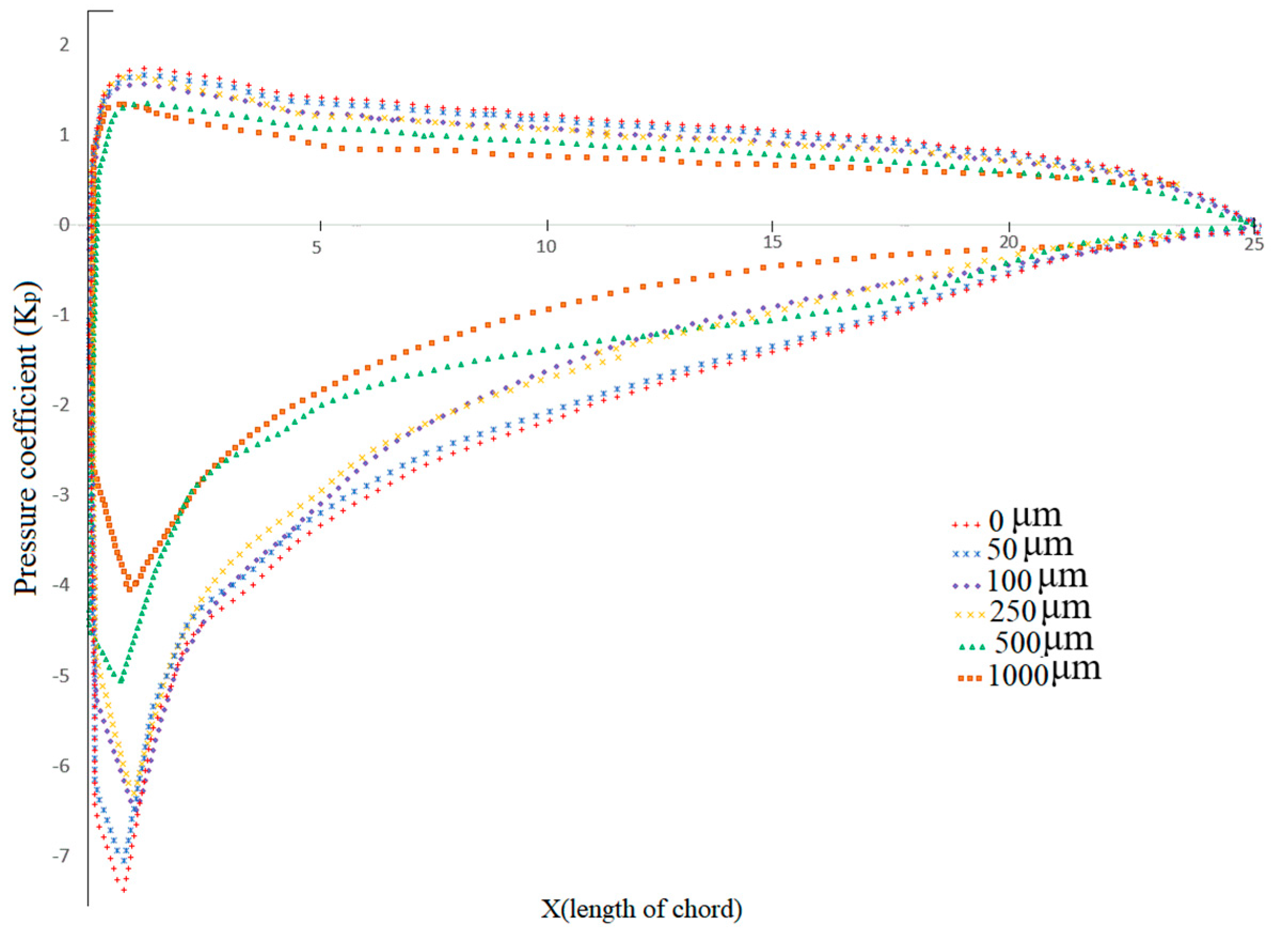
The gradient of pressure between the suction surface and the pressure surface leads to a rotational torque for the shaft of the turbine [47]. To analyze this, the pressure coefficient (Kp) was calculated using the CFD model results and Equation (10) at various roughness heights and the results are presented in Figure 11.
It can be seen that the pressure coefficient is very sensitive to surface roughness. The margin of the pressure coefficient (Kp) between the top and bottom surfaces of the airfoil decreased with the roughness height increasing from 0 to 1000 μm, particularly for the front location of 30% of the chord length. In addition, at the leading edge, the pressure difference between the top and bottom surfaces is greater relative to the other positions. This reduction of the pressure coefficient will reduce the torque, as well as power output which will be explained in the following section. These results are consistent with those presented in Li et al. [48] who also reported that the margin of variation of the pressure coefficient decreases with increasing roughness.
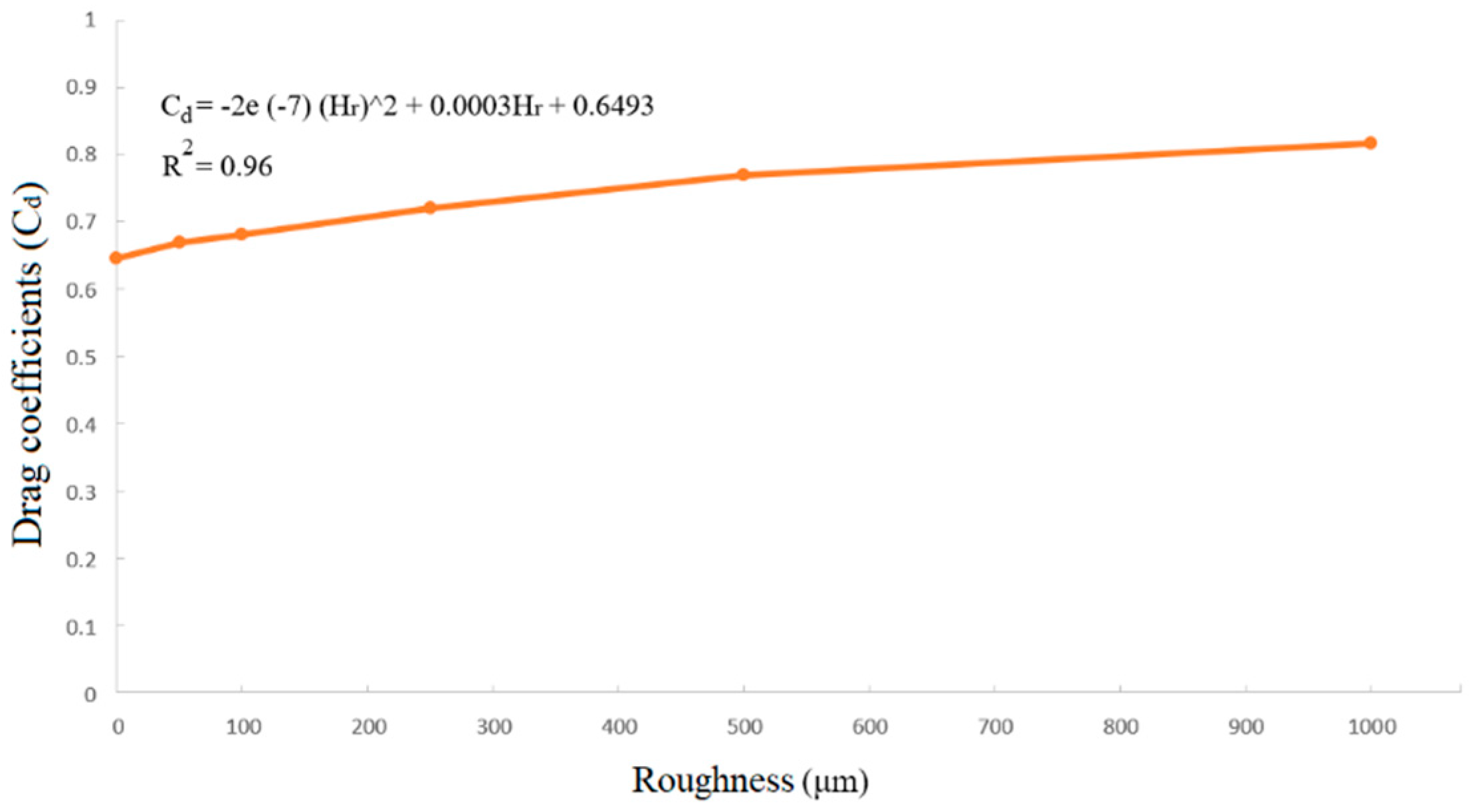
Drag coefficient (Cd) is one of the most important flow parameters which has influence on the performance of tidal turbines [49]. In this section, the amount of change in drag coefficient due to the roughness height in DH turbine with NACA 0015 airfoil is quantified. Similar to Kp, Cd [50] was calculated using the CFD model for different roughness heights and the results are presented in Figure 12. The results show that Cd increases gradually (following a second order polynomial function) with increasing roughness. The value of Cd at Hr = 1000 μm is 20% higher than the smooth blade. This trend of variation is generally consistent with the results reported by Ren and Ou [51] for a wind turbine with a NACA 63–430 airfoil.

6.1.3. Effects of Surface Roughness on Torque, T

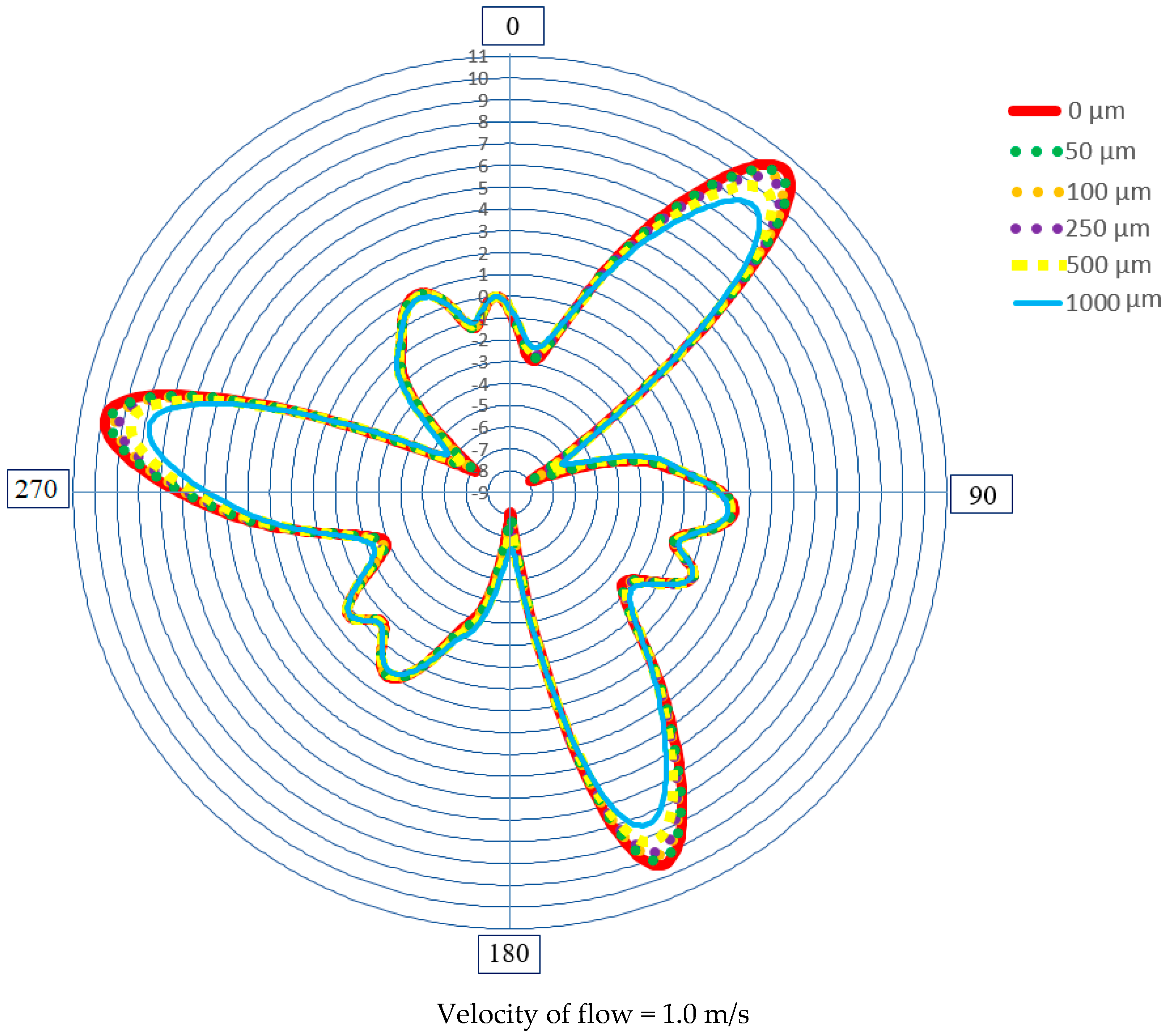
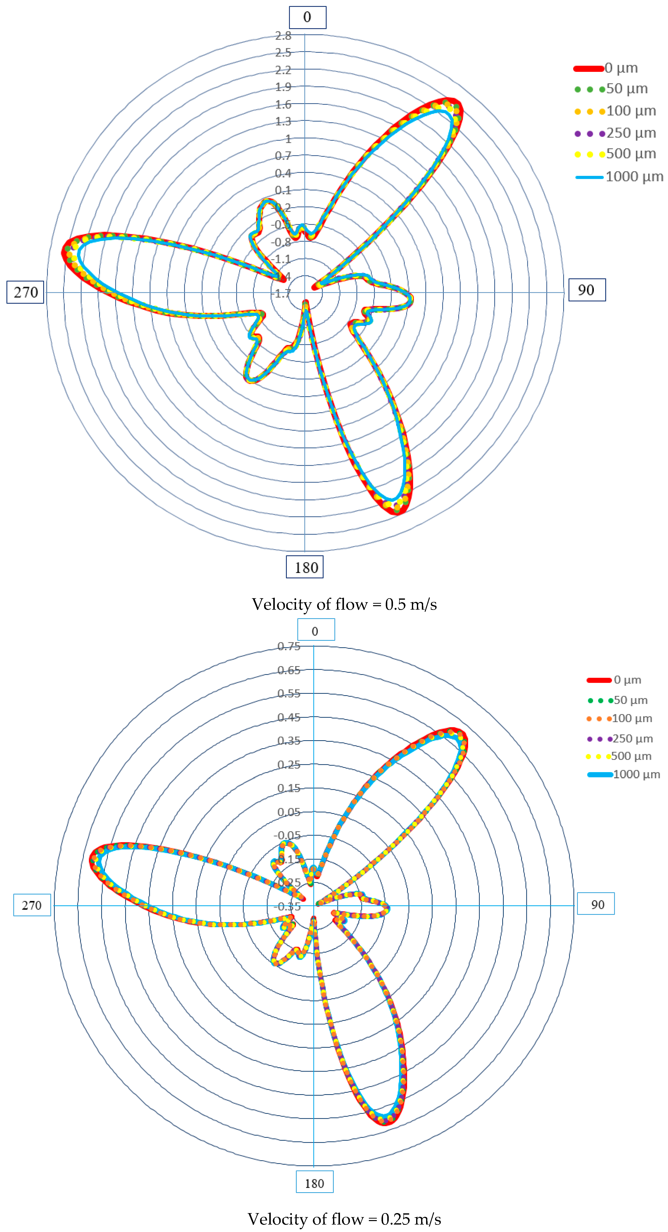
As mentioned above, surface roughness causes an increase in the drag coefficient and decrease in pressure coefficient, both of which reduce the output torque of the turbine. To evaluate this effect, the Torque (T) of the DH turbine was calculated in six different average roughness heights of 0, 50, 100, 250, 500, and 1000 μm. Furthermore, in order to determine which range of velocity inlet (which is representative of Reynolds number) has greater influence on the turbine, CFD simulations were carried out with Uw of 0.25, 0.5, and 1.0 m/s. The results of torque versus azimuthal angle for six different roughness heights for three different inlet velocities are presented in Figure 13. As it can be seen, amongst the three inlet velocities, the range of 0–250 μm roughness height has a negligible impact on output torque of the turbine. On the other hand, Hr between 250–1000 μm has a significant effect on the turbine and it is the worst at velocity of 1.0 m/s. The results indicate that the effect of roughness is much greater at high Reynolds numbers. This finding is in agreement with the results reported in previous research [52,53,54,55]. Since a lower torque usually produces a lower energy output [56], it can be concluded that energy losses are caused by increase in the roughness to the DH turbine blade.

6.1.4. Effects of Surface Roughness on Power Loss, Pl

Roughness on blades almost always reduces the power output of wind turbines, and the loss usually varies from 20% to 50% [57,58]. In the same way that insects reduce the output power of wind turbines [59,60,61], dogged marine animals and erosion can reduce the efficiency of hydro turbines by increasing roughness on blades. Equations (12) and (13), together with the CFD model results were used to calculate the power loss of the DH turbine in different roughness heights at velocity of 1 m/s [62].
P = T m × ω
P l % = P c P r P r × 100 %
where P: Power; Pl: Power loss; Pc = Power of clean turbine; Pr: Power of roughed turbine; Tm: Mean torque; ω: Angular velocity.
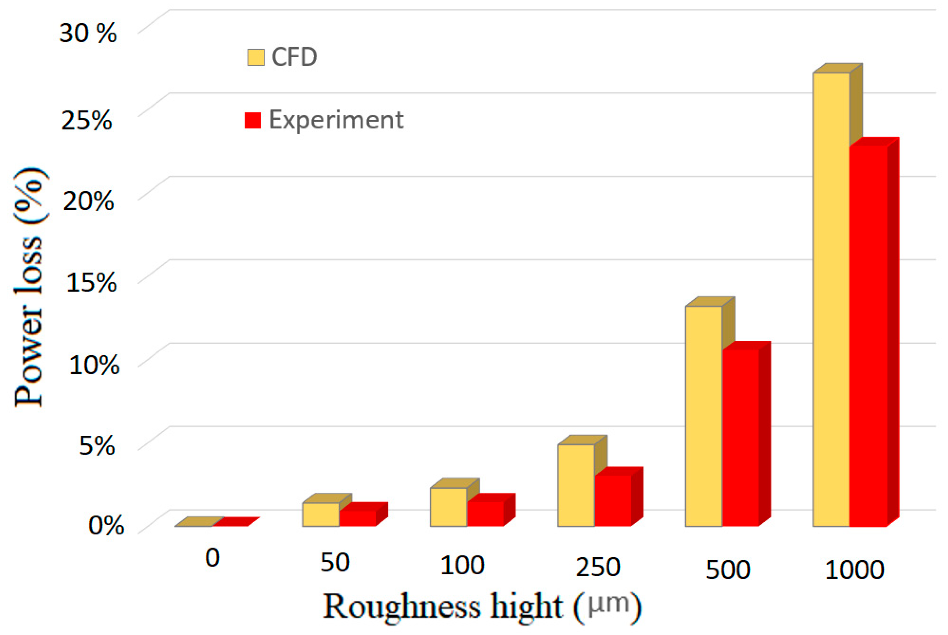
The turbine’s output power is equal to its angular velocity (ω) times the torque (T) that acts on it (Equation (12)). Since the torque and angular velocity of DH turbine are not constant, the output power is also not constant. Thus, the average output power is calculated. The percentage of power loss of the DH turbine under six different roughness heights at Uw = 1.0 m/s is shown in Figure 14.

6.2. Experimental Results

The results of the laboratory experiments on the effects of surface roughness on the flow and energy loss are presented in this section. Figure 15 shows the DH turbine blades with six different surface roughness values created by rolled waterproof sandpapers with different surface roughness. The experimental results are shown in Figure 14. The results show that the energy loss increases nonlinearly with increase in the surface roughness. Amongst the roughness heights used, the maximum percentage of power loss could reach up to 27% (numerical) and 22% (experimentally) for 1000 μm roughness. The amount of reduction in power for Hr ≤ 100 μm is less than about 3%.

7. Conclusions

This paper presented an experimental and CFD analysis of impact of surface roughness on hydrodynamic performance of a DH turbine. It was shown that surface roughness is a crucial factor in designing a hydro turbine which should be considered as an initial design parameter such as the number of blades, size of blades, tip speed ratio (ζ), water velocity, and shape of airfoils. The higher the roughness of the blade of DH turbine, the lower is the turbine performance. CFD simulations were used to quantify the effects of roughness on stream flow and performance of the turbine. Furthermore, physical models of DH turbine with six different roughness heights were tested experimentally. The following conclusions can be drawn from the results obtained in this research:
(1)
Velocity distributions show that turbulence will increase with increasing the surface roughness of DH turbine. Turbulence reduces the kinetic energy which in turn, reduces the total turbine efficiency.
(2)
The surface roughness degrades the margin of pressure coefficient, especially at high values of roughness.
(3)
The drag coefficient increases as a second order polynomial function of Hr. When NACA 0015 airfoil is used in DH turbine, the drag coefficient is very sensitive to the variations of Hr. The drag coefficient of roughed turbine (with Hr = 1000 μm) studied in this paper was 20% higher than the smooth blade.
(4)
The average torque shows small changes at low flow velocities. The adverse impact of surface roughness is significantly greater at high inlet velocities (i.e., high Reynold numbers). In the CFD simulation, all parameters in the Re equation were constant except the velocity of water. It was shown that the negative impacts of roughness are much greater at high Reynolds numbers.
(5)
The decrease in torque due to surface roughness reduces the output power of the turbine. For the turbine studied in this research, the maximum reductions in output power numerically and experimentally were about 27% and 22% for Hr = 1000 μm, respectively.
(6)
The results of this research would be useful for manufacturers and operators of DH turbines in decisions about practical measures (e.g., coating or cleaning of blades) to reduce roughness of the turbine blades.

Author Contributions

Conceptualization, M.H.K. and A.A.J.; methodology, M.H.K. and A.A.J.; software, M.H.K. and A.A.J.; validation, M.H.K. and A.A.J.; formal analysis, M.H.K. and A.A.J.; investigation, M.H.K. and A.A.J.; resources, M.H.K. and A.A.J.; data curation, M.H.K. and A.A.J.; writing—original draft preparation, M.H.K.; writing—review and editing, A.A.J.; visualization, M.H.K. and A.A.J.; supervision, A.J; project administration, M.H.K. and A.A.J.; funding acquisition, A.A.J. All authors have read and agreed to the published version of the manuscript.

Funding

This research received no external funding.

Conflicts of Interest

The authors declare no conflict of interest.

References

  1. Akinyele, D.; Rayudu, R. Review of energy storage technologies for sustainable power networks. Sustain. Energy Technol. Assess. 2014, 8, 74–91. [Google Scholar] [CrossRef]
  2. Gunn, K.; Stock-Williams, C. Quantifying the global wave power resource. Renew. Energy 2012, 44, 296–304. [Google Scholar] [CrossRef]
  3. Dunnett, D.; Wallace, J.S. Electricity generation from wave power in Canada. Renew. Energy 2009, 34, 179–195. [Google Scholar] [CrossRef]
  4. Khanjanpour, M.; Javadi, A.; Akrami, M. CFD analyses of a tidal hydro-turbine (THT) for utilising in sea water desalination. In Proceedings of the ISER 209th International Conference, London, UK, 7 July 2019. [Google Scholar]
  5. Soleimani, K.; Ketabdari, M.J.; Khorasani, F. Feasibility study on tidal and wave energy conversion in Iranian seas. Sustain. Energy Technol. Assess. 2015, 11, 77–86. [Google Scholar] [CrossRef]
  6. Hammons, T.J. Tidal power. Proc. IEEE 1993, 81, 419–433. [Google Scholar] [CrossRef]
  7. Antonio, F.d.O. Wave energy utilization: A review of the technologies. Renew. Sustain. Energy Rev. 2010, 14, 899–918. [Google Scholar]
  8. Mohamed, M. Performance investigation of H-rotor Darrieus turbine with new airfoil shapes. Energy 2012, 47, 522–530. [Google Scholar] [CrossRef]
  9. Batten, W.M.J.; Bahaj, A.S.; Molland, A.F.; Chaplin, J.R. Experimentally validated numerical method for the hydrodynamic design of horizontal axis tidal turbines. Ocean Eng. 2007, 34, 101–1020. [Google Scholar] [CrossRef]
  10. Batten, W.M.J.; Bahaj, A.S.; Molland, A.F.; Chaplin, J.R. The prediction of the hydrodynamic performance of marine current turbines. Renew. Energy 2008, 33, 1085–1096. [Google Scholar] [CrossRef]
  11. Thiébot, J.; Du Bois, P.B.; Guillou, S. Numerical modeling of the effect of tidal stream turbines on the hydrodynamics and the sediment transport–Application to the Alderney Race (Raz Blanchard), France. Renew. Energy 2015, 75, 356–365. [Google Scholar] [CrossRef]
  12. Batten, W.M.J.; Bahaj, A.S.; Molland, A.F.; Chaplin, J.R. Hydrodynamics of marine current turbines. Renewable energy 2006, 31, 249–256. [Google Scholar] [CrossRef] [Green Version]
  13. Polagye, B. Hydrodynamic Effects of Kinetic Power Extraction by In-Stream Tidal Turbines; University of Washington: Seattle, WA, USA, 2009. [Google Scholar]
  14. Mahmud, S.; Sampebatu, L.; Kwang, S.C. Mechanical Power efficiency of Modified Turbine Blades. In AIP Conference Proceedings; AIP Publishing: Melville, NY, USA, 2017. [Google Scholar]
  15. Shaheen, M.; Abdallah, S. Efficient clusters and patterned farms for Darrieus wind turbines. Sustainable Energy Technol. Assess. 2017, 19, 125–135. [Google Scholar] [CrossRef]
  16. Hau, E. Wind Turbines: Fundamentals, Technologies, Application, Economics; Springer Science & Business Media, 2013. [Google Scholar]
  17. Kiho, S.; Shiono, M.; Suzuki, K. The power generation from tidal currents by Darrieus turbine. Renew. Energy 1996, 9, 1242–1245. [Google Scholar] [CrossRef]
  18. Joubert, J.R.; L.v.N., J.; Reinecke, J.; Meyer, I. Wave Energy Converters (WECs); CRSES: Matieland, South Africa, 2013. [Google Scholar]
  19. Rasool, G.; Johnstone, C.; Stack, M.M. Tribology of Tidal Turbine Blades: Impact angle Effects on Erosion of Polymeric Coatings in Sea Water Conditions. In Proceedings of the Asian Wave and Tidal Energy Conference (AWTEC), Marina Bay Sands, Singapore, 24–28 October 2016. [Google Scholar]
  20. Walker, J.M.; Flack, K.A.; Lust, E.E.; Schultz, M.P.; Luznik, L. Experimental and numerical studies of blade roughness and fouling on marine current turbine performance. Renew. Energy 2014, 66, 257–267. [Google Scholar] [CrossRef]
  21. Maruzewski, P.; Hasmatuchi, V.; Mombelli, H.P.; Burggraeve, D.; Iosfin, J.; Finnegan, P.; Avellan, F. Surface roughness impact on Francis turbine performances and prediction of efficiency step up. Int. J. Fluid Mach. Syst. 2009, 2, 353–362. [Google Scholar] [CrossRef]
  22. Priegue, L.; Stoesser, T. The influence of blade roughness on the performance of a vertical axis tidal turbine. Int. J. Mar. Energy 2017, 17, 136–146. [Google Scholar] [CrossRef]
  23. Mehmood, N. Study of naca 0015 for diffuser design in tidal current turbine applications. Int. J. Eng. 2012, 25, 373–380. [Google Scholar] [CrossRef]
  24. Coiro, D.; Nicolosi, F.; De Marco, A.; Melone, S.; Montella, F. Flow curvature effect on dynamic behaviour of a novel vertical axis tidal current turbine: Numerical and experimental analysis. In ASME 2005 24th International Conference on Offshore Mechanics and Arctic Engineering; American Society of Mechanical Engineers Digital Collection, 2005. [Google Scholar]
  25. Xiao, Q.; Zhu, Q. A review on flow energy harvesters based on flapping foils. J. Fluids Struct. 2014, 46, 174–191. [Google Scholar] [CrossRef]
  26. Lanzafame, R.; Mauro, S.; Messina, M. Wind turbine CFD modeling using a correlation-based transitional model. Renew. Energy 2013, 52, 31–39. [Google Scholar] [CrossRef]
  27. Nabavi, Y. Numerical Study of the duct Shape Effect on the Performance of a Ducted Vertical Axis Tidal Turbine; University of British Columbia: Vancouver, BC, Canada, 2008. [Google Scholar]
  28. Yang, W.; Wu, Y.; Liu, S. An optimization method on runner blades in bulb turbine based on CFD analysis. Sci. China Technol. Sci. 2011, 54, 338–344. [Google Scholar] [CrossRef]
  29. Castelli, M.; De Betta, S.; Benini, E. Numerical investigation of the optimal spatial domain discretization for the 2-D analysis of a Darrieus vertical-axis water turbine. In Proceedings of the World Academy of Science, Engineering and Technology, Paris, France, 25–26 April 2012. [Google Scholar]
  30. Lain, S.; Osorio, C. Simulation and Evaluation of a Straight-Bladed Darrieus-Type cross Flow Marine Turbine. J. Sci. Industr. Res. 2010, 69, 906–912. [Google Scholar]
  31. Balduzzi, F.; Bianchini, A.; Maleci, R.; Ferrara, G.; Ferrari, L. Critical issues in the CFD simulation of Darrieus wind turbines. Renew. Energy 2016, 85, 419–435. [Google Scholar] [CrossRef]
  32. Nobile, R.; Vahdati, M.; Barlow, J.F.; Mewburn-Crook, A. Unsteady flow simulation of a vertical axis augmented wind turbine: A two-dimensional study. J. Wind Eng. Ind. Aerodyn. 2014, 125, 168–179. [Google Scholar] [CrossRef] [Green Version]
  33. Dai, Y.; Lam, W. Numerical study of straight-bladed Darrieus-type tidal turbine. Proc. Inst. Civil Eng. -Energy 2009, 162, 67–76. [Google Scholar] [CrossRef]
  34. Liu, Z.; Qu, H.; Shi, H. Numerical Study on Self-Starting Performance of Darrieus Vertical Axis Turbine for Tidal Stream Energy Conversion. Energies 2016, 9, 789. [Google Scholar] [CrossRef] [Green Version]
  35. Menter, F.R. Two-equation eddy-viscosity turbulence models for engineering applications. AIAA J. 1994, 32, 1598–1605. [Google Scholar] [CrossRef] [Green Version]
  36. Pang, A.L.J.; Skote, M.; Lim, S.Y. Modelling high Re flow around a 2D cylindrical bluff body using the k-ω (SST) turbulence model. Prog. Comput. Fluid Dyn. Int. J. 2016, 16, 48–57. [Google Scholar] [CrossRef]
  37. Adedeji, O.E.; Yu, W.; Sanders, R.S. Analysis of local wear variables for high-precision erosion modelling in complex geometries. Wear 2019, 426, 562–569. [Google Scholar] [CrossRef]
  38. Sommerfeld, M.; Huber, N. Experimental analysis and modelling of particle-wall collisions. Int. J. Multiph. Flow 1999, 25, 1457–1489. [Google Scholar] [CrossRef]
  39. Fluent, A. 19.2 Theory Guide; ANSYS. Inc.: Canonsburg, PA, USA, 2018. [Google Scholar]
  40. Pattanapol, W.; Wakes, S.J.; Hilton, M.J.; Dickinson, K.J. Modeling of surface roughness for flow over a complex vegetated surface. Int. J. Math. Phys. Eng. Sci. 2008, 2, 18–26. [Google Scholar]
  41. Menter, F. Two-equation eddy-viscosity turbulence models for engineering applications. AIAA J. 2002, 40, 254–266. [Google Scholar] [CrossRef] [Green Version]
  42. Cebeci, T.; Bradshaw, P. Momentum Transfer in Boundary Layers; Hemisphere Publishing Corp.: Washington, DC, USA; McGraw-Hill Book Co.: New York, NY, USA, 1977; Volume 407, p. 1977. [Google Scholar]
  43. TAN, M.G.; LIU, H.L.; WU, X.F.; WANG, Y.; WANG, K.; FU, M. The Effect of Roughness on the Numerical Prediction of the Characteristics of Centrifugal Pumps. China Rural Water Hydropower 2011, 2. [Google Scholar]
  44. Sagol, E.; Reggio, M.; Ilinca, A. Issues concerning roughness on wind turbine blades. Renew. Sustain. Energy Rev. 2013, 23, 514–525. [Google Scholar] [CrossRef]
  45. Villalpando, F.; Reggio, M.; Ilinca, A. Numerical study of flow around iced wind turbine airfoil. Eng. Appl. Comput. Fluid Mech. 2012, 6, 39–45. [Google Scholar] [CrossRef] [Green Version]
  46. Ehrmann, R.S. Effect of Surface Roughness on Wind Turbine Performance. J. Phys. 2014, 1037. [Google Scholar]
  47. Hodson, H.; Dominy, R. Three-Dimensional Flow in a Low-Pressure Turbine Cascade at its Design Condition. J. Turbomach. 1987, 109, 177–185. [Google Scholar] [CrossRef]
  48. Li, D.; Li, R.; Yang, C.; Wang, X. Effects of surface roughness on aerodynamic performance of a wind turbine airfoil. In Proceedings of the 2010 Asia-Pacific Power and Energy Engineering Conference, Chengdu, China, 28–31 March 2010. [Google Scholar]
  49. Ahmed, M.R. Blade sections for wind turbine and tidal current turbine applications–current status and future challenges. Int. J. Energy Res. 2012, 36, 829–844. [Google Scholar] [CrossRef]
  50. Cruz, A.G.B.d.; Mesquita, A.L.A.; Blanco, C.J.C. Minimum pressure coefficient criterion applied in axial-flow hydraulic turbines. J. Braz. Soc. Mech. Sci. Eng. 2008, 30, 30–38. [Google Scholar] [CrossRef] [Green Version]
  51. Ren, N.; Ou, J. Numerical simulation of surface roughness effect on wind turbine thick airfoils. In Proceedings of the 2009 Asia-Pacific Power and Energy Engineering Conference, Wuhan, China, 28–31 March 2009. [Google Scholar]
  52. Freudenreich, K.; Kaiser, K.; Schaffarczyk, A.P.; Winkler, H.; Stahl, B. Reynolds number and roughness effects on thick airfoils for wind turbines. Wind Eng. 2004, 28, 529–546. [Google Scholar] [CrossRef]
  53. Montomoli, F.; Hodson, H.; Haselbach, F. Effect of roughness and unsteadiness on the performance of a new low pressure turbine blade at low Reynolds numbers. J. Turbomach. 2010, 132, 031018. [Google Scholar] [CrossRef]
  54. Timmer, W.; Schaffarczyk, A. The effect of roughness at high Reynolds numbers on the performance of aerofoil DU 97-W-300Mod. Wind Energy Int. J. Prog. Appl. Wind Power Convers. Technol. 2004, 7, 295–307. [Google Scholar] [CrossRef]
  55. Blair, M.F. The Effects of Reynolds Number, Rotor Incidence Angle and Surface Roughness on the Heat Transfer Distribution in a Large-Scale Turbine Rotor Passage; NASA: East Hartford, CT, USA, 1991. [Google Scholar]
  56. Virk, M.S.; Homola, M.C.; Nicklasson, P.J. Effect of rime ice accretion on aerodynamic characteristics of wind turbine blade profiles. Wind Eng. 2010, 34, 207–218. [Google Scholar] [CrossRef]
  57. Laakso, T.; Baring-Gould, I.; Cattin, R.; Durstewitz, M.; Hulkkonen, M.; Krenn, A.; Lacroix, A.; Peltola, E.; Ronsten, G.; Tallhaug, L.; et al. Wind energy projects in cold climates. Int. Energy Agency 2005, 36. [Google Scholar]
  58. Dalili, N.; Edrisy, A.; Carriveau, R. A review of surface engineering issues critical to wind turbine performance. Renew. Sustain. Energy Rev. 2009, 13, 428–438. [Google Scholar] [CrossRef]
  59. Corten, G.P.; Veldkamp, H.F. Insects Cause Double Stall; Netherlands Energy Research Foundation: Petten, The Netherlands, 2001. [Google Scholar]
  60. Corten, G.P.; Veldkamp, H.F. Aerodynamics: Insects can halve wind-turbine power. Nature 2001, 412, 41. [Google Scholar] [CrossRef]
  61. Lachmann, G.V. Aspects of Insect Contamination in Relation to Laminar flow Aircraft; Ministry of Aviation, Aeronautical Research Council, 1960. [Google Scholar]
  62. Zhang, Y.; Igarashi, T.; Hu, H. Experimental investigations on the performance degradation of a low-Reynolds-number airfoil with distributed leading edge roughness. In Proceedings of the 49th AIAA Aerospace Sciences Meeting Including the New Horizons Forum and Aerospace Exposition, Orlando, FL, USA, 4–7 January 2011. [Google Scholar]
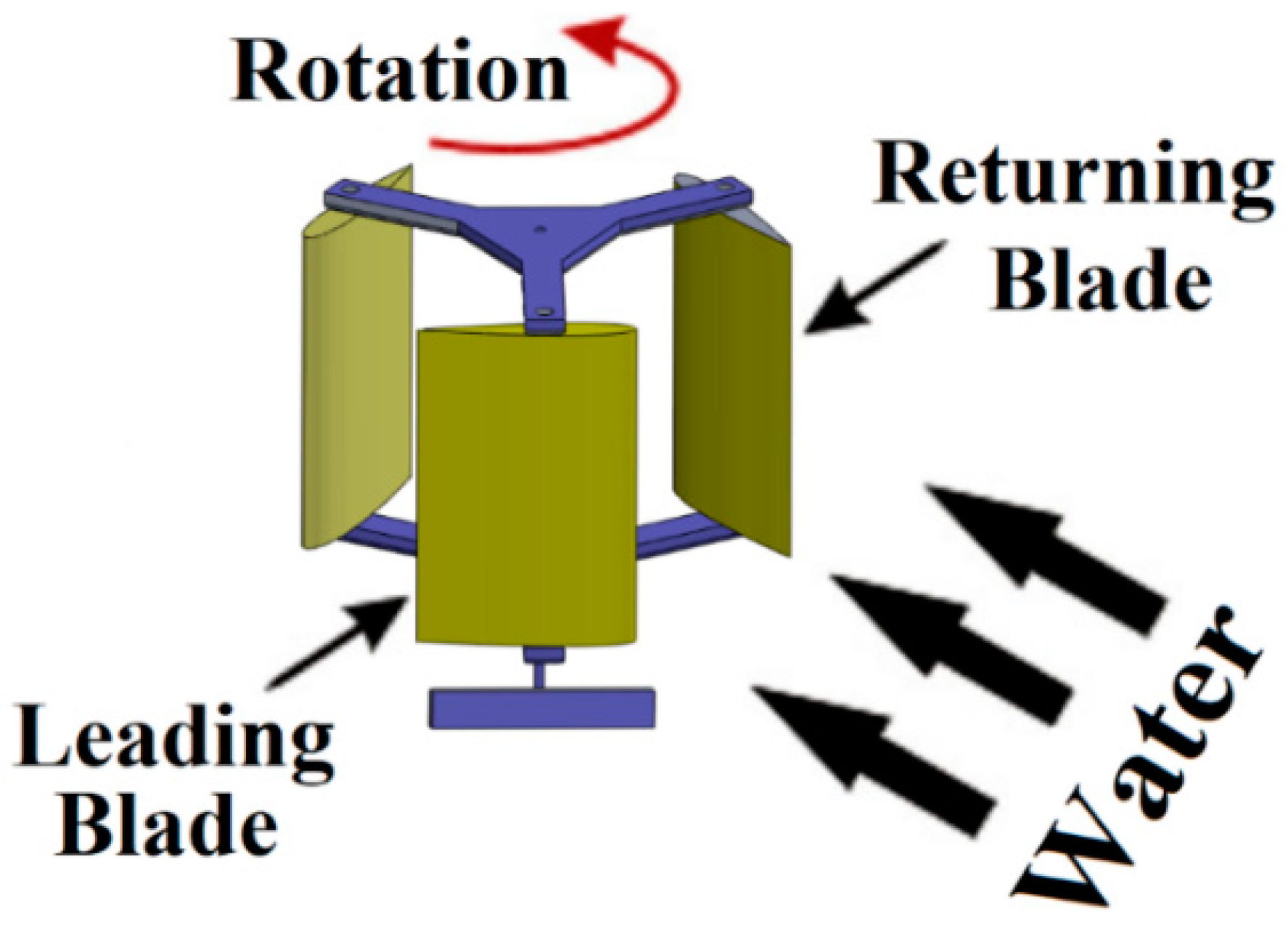
Figure 1. Schematic of the Darrius hydro (DH) turbine.
Energies 13 00928 g001
Figure 2. Computational domain and mesh blocks.
Energies 13 00928 g002
Figure 3. Circular domain and intensive mesh on walls of the blades of NACA 0015 airfoil (using ICEM ANSYS 2019).
Energies 13 00928 g003
Figure 4. Average torque coefficient vs. number of cells for grid sensitivity test.
Energies 13 00928 g004
Figure 5. Torque coefficient (Cm) vs. azimuthal angle for five different time steps.
Energies 13 00928 g005
Figure 6. Measurement system for the DH turbine.
Energies 13 00928 g006
Figure 7. Experiments in hydraulic laboratory of University of Exeter.
Energies 13 00928 g007
Figure 8. Power coefficient (CP) vs. tip speed ratio (ζ) for validation of the computational fluid dynamics (CFD) model with the experimental work.
Energies 13 00928 g008
Figure 9. Distribution of velocity for various roughness heights on NACA 0015 airfoil at ζ = 1.5.
Energies 13 00928 g009
Figure 10. Velocity vectors in various roughness heights at ζ = 1.5 and angle of 60°.
Energies 13 00928 g010
Figure 11. Pressure coefficient (Kp) curves on a single NACA 0015 blade at different roughness heights.
Energies 13 00928 g011
Figure 12. Variations of drag coefficient (Cd) at different roughness heights.
Energies 13 00928 g012
Figure 13. Torque (T) vs. azimuthal angle for six different roughness heights at ζ = 1.5.
Energies 13 00928 g013aEnergies 13 00928 g013b
Figure 14. Percentage of power loss of the DH turbine with NACA 0015 airfoil for six different roughness heights (Uw = 1.0 m/s).
Energies 13 00928 g014
Figure 15. Experimental cases with different roughness values.
Energies 13 00928 g015
Table 1. Turbine geometrical and stream specifications.
Height of blade0.45 m
Length of chord 0.3 m
Number of blades3
Type of airfoil NACA 0015
Velocity of water 1 m/s