Article

Control the Voltage Instabilities of Distribution Lines using Capacitive Reactive Power

Department of Electric/Electronic Engineering, Ariel University, Ariel 40700, Israel
*
Authors to whom correspondence should be addressed.
Both authors contributed equally to this work.
Energies 2020, 13(4), 875; https://doi.org/10.3390/en13040875
Submission received: 12 January 2020 / Revised: 13 February 2020 / Accepted: 15 February 2020 / Published: 17 February 2020
(This article belongs to the Section F: Electrical Engineering)

Abstract

:
The voltage instabilities in the distribution lines are primarily related to the integration of photovoltaic power plants with the local grids. Conventional tap-changers cannot compensate for the rapid disparities between generated and consumed power because of sluggish dynamic response. This article presents an effective method and control algorithm to improve the voltage instabilities of distribution lines. Analytical calculation confirms that the application of capacitive reactive power on load is beneficial to keep the voltage at the permissible level. Importantly, the severe concern about the current increment with voltage enhancement is also addressed. The dynamic behavior during capacitance switching is studied using simulation experiments. It is suggested that capacitance is connected to the load for the only time of voltage drop until the transformation ratio changes to the desired level. This article provides an explanation and solution for voltage deviations of electricity distribution lines in steady-state and dynamic modes.

1. Introduction

In recent days, photovoltaic (PV) power systems are becoming an important component to fulfill energy demands. Several PV power systems are connected with the local grids, and the simultaneous operation of these PV systems provokes voltage instabilities in the distribution lines [1,2]. These voltage fluctuations can occur over the permissible limits and are not allowed for standard devices. It is well-known that abrupt changes in electrical power generation are a distinctive feature of PV solar plants [3]. At every substation, the transformers are installed to link the transmission line with a distribution line. The transformers are equipped with a tap-changer, which regulates the output voltage by exchanging the transformation ratio. These tap-changers, being electro-mechanical appliances, have a sluggish response time of seven to ten seconds. This time is required to toggle only one section of the transformer, which leads to discrete voltage step-up or step-down. Therefore, the rapid imbalance between consumed and generated power cannot be corrected effectively. Moreover, it is difficult to predict the deviations in power consumption.
Previously, several solutions have been proposed to prevent voltage instabilities in the distribution lines [2,4,5,6,7,8,9,10,11,12,13,14,15]. These solutions have suggested to use reactive power in distribution lines during voltage instabilities. The reactive power generation devices can be connected to the load in serial or shunt arrangements [16,17]. Different types of technologies have been used to produce reactive power for compensation such as static synchronous compensator (STATCOM), synchronous condenser, static var compensator (SVC), and capacitors [14,18,19,20,21,22]. Electronic devices are effective for reactive power compensation but significantly complicated, expensive, and not reliable enough [18,23]. In the case of voltage disturbances, it is required to control the production of reactive power in the distribution lines. Several effective control algorithms have been proposed for this purpose [24,25,26,27,28]. These algorithms include Takagi–Sugeno–Kang probabilistic fuzzy neural network control [24], instantaneous active/reactive power control strategy for flicker mitigation [25], single-point reactive power control method [26], decoupled active and reactive power predictive control [27], adaptive reactive power control [28], etc. However, the response time of these algorithms is relatively slow.
One of the effective methods for the production of reactive power is to connect capacitors at the load or the end of distribution lines. The response time can be significantly diminished using this method. However, an open question remains unanswered that what magnitude of capacitance should be connected to the load. Some of the early examples of reactive power applications using capacitors are described by previous studies [29,30]. The capacitor can be serially connected to the load, but this method is problematic for loads with substantial power and consuming currents [29]. Another method can be applied only for autonomous wind turbine power plants [30]. More importantly, the dynamic process of a current change during the capacitor’s connection to a load is not considered enough. The significant enhancement of the current magnitude during the switching process is also an essential issue for consideration.
In this study, we proposed an efficient method to prevent voltage stabilities in the distribution line. In the proposed method, the bank of capacitors is connected at the loads or end of the distribution line. The algorithm offers to select optimal capacitors needed to improve the voltage instabilities. As well, the dynamic process of current alteration during capacitors connection analyzes and proposes optimal switching.

2. Description of the Problem

Let us try to understand and analyze the origin of the problem. Figure 1 demonstrates the single line diagram of the electric power grid and related infrastructure located at Jordan Valley, Israel.
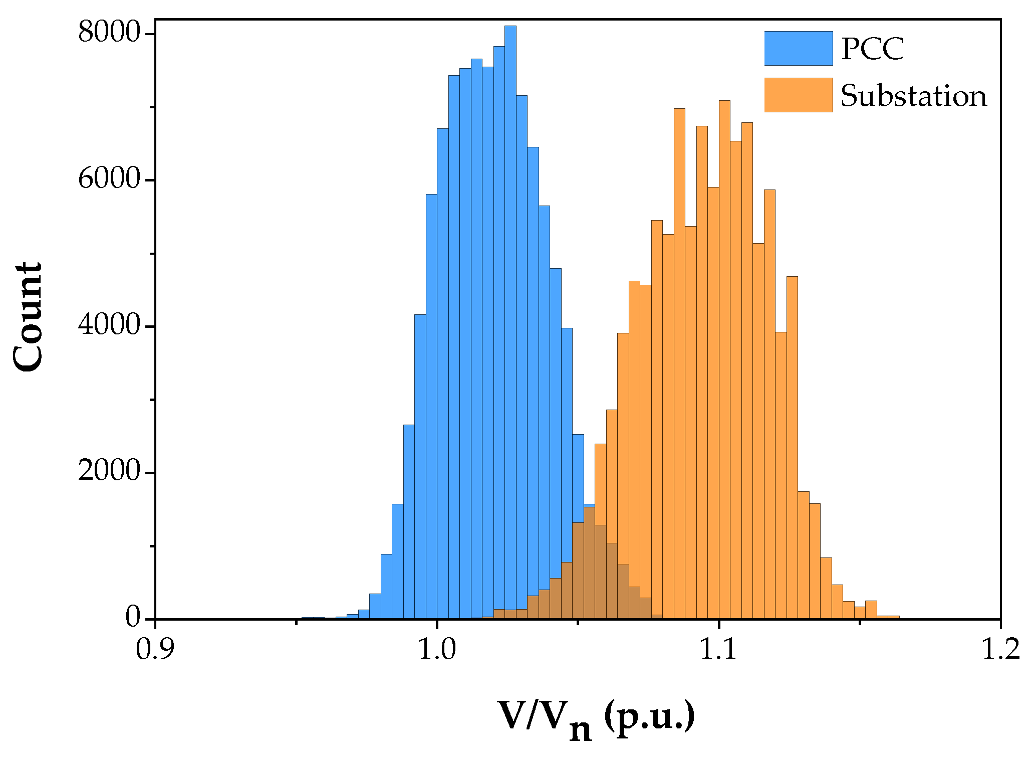
Figure 2 represents the voltage measured at the PCC and substation of the abovementioned distribution line during the year 2019. The measurements and data acquisition were performed using the 6-analog input module MOSCAD-L RTU (Motorola, Inc.) [31]. The device measures the rms voltage value of each 5 minutes sampling period based on 15,000 points. The length of distribution line is 22.5 km, and this line is connected with the substation of 161/33 kV, 30 MVA. The impedance of a single phase is 4.93 + j14.01 Ω, and the phasor is 14.85 70.6°. The PV power plants with a total nominal power of 6.1 MW is installed with this line.
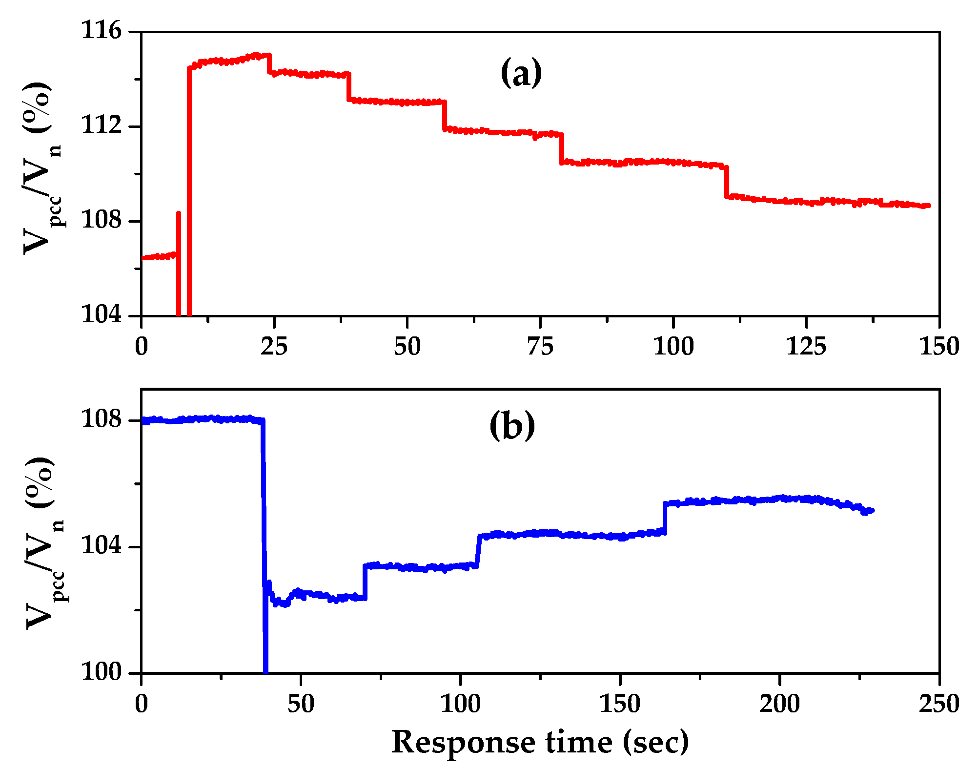
During voltage instabilities, the functionality of tap-changers installed with transformers is demonstrated in Figure 3. The measurements were performed at PCC using a handheld power quality analyzer [32]. It can be seen from the figure that the sluggish response of tap-changers (40–60 sec) takes a long time to achieve the nominal voltage. As a result, the voltage magnitude overcomes both maximum and minimum permissible levels (Figure 2). Such voltage fluctuations are forbidden for the standard devices and also crucial for specific equipment. These circumstances motivate us to find the appropriate solution and reflect the importance of the presented study.

3. Methodology

The proposed method is based on the analysis of steady-state operation mode. Let us consider that the active-inductive load and capacitance are connected with the distribution line. The equivalent circuit diagram of such an arrangement is shown in Figure 4. The distribution line and a load are considered using lumped elements.
The relationship between output and input voltages is determined using the nodal theorem-based equivalent circuit analysis:
V ˙ O V ˙ S R 1   +   j X 1   +   V ˙ O R 2   +   V ˙ O j X 2   +   V ˙ O j X C   =   0 ,
where V ˙ O and V ˙ S are output voltage and source voltage, respectively. All solutions of Equation (1) are transformed into a dimensionless representation for ease of analysis. After the rearrangement and simplification, the coefficient of output voltage amplification (λ) is expressed as:
λ   =   | V ˙ O V ˙ S |   =   1 ( 1   +   R 1 R 2   +   X 1 X 2 X 1 X C ) 2   +   ( R 1 X C   +   X 1 R 2 R 1 X 2 ) 2 ,
Figure 5 shows the relationship between λ and X C for defined parameters of R 1   = 1 Ω, X 1   = 3 Ω, R 2 = 100 Ω, X 2 = 276 Ω, cos( R 2 || X 2 ) = 0.94.
The optimal value of X C corresponds to the maximum voltage amplification (λ) can be calculated using preliminary transformations in Equation (2):
λ 2 = 1 ( 1   +   R 1 R 2   +   X 1 X 2 X 1 X C ) 2 + ( R 1 X C + X 1 R 2 R 1 X 2 ) 2 = X C 2 ( ( 1 + R 1 R 2   +   X 1 X 2 ) X C X 1 ) 2   +   ( ( X 1 R 2 R 1 X 2 ) X C   +   R 1 ) 2
λ 2   =   X C 2 ( α X C X 1 ) 2   +   ( β X C   +   R 1 ) 2 m a x ,
where α   =   ( 1   +   R 1 R 2   +   X 1 X 2 ) , and β   =   ( X 1 R 2 R 1 X 2 ) . The optimal value of X C can be determined by the following condition:
d ( λ 2 ) d X C   =   0 ,
2 X C ( α X 1 X C   +   β R 1 X C   +   X 1 2   +   R 1 2 ) [ ( ( 1   +   R 1 R 2   +   X 1 X 2 ) X C X 1 ) 2   +   ( ( X 1 R 2 R 1 X 2 ) X C   +   R 1 ) 2 ] 2   =   0 ,
We arrive at,
α X 1 X C   +   β R 1 X C   +   X 1 2   +   R 1 2   =   0 ,
The optimal value of X C is expressed as:
( X C ) o p t   =   X 1 2   +   R 1 2 α X 1 β R 1   =   Z L i n e α X 1 Z L i n e β R 1 Z L i n e   =   Z L i n e α s i n ( Z L i n e ) β c o s ( Z L i n e ) ,
where Z L i n e   =   R 1 2   +   X 1 2 , s i n ( Z L i n e )   =   X 1 Z L i n e , c o s ( Z L i n e )   =   R 1 Z L i n e are the line impedance and the sine of the line impedance, respectively. The optimum value of capacitance ( C o p t ) is calculated as:
C o p t   =   α s i n ( Z L i n e ) β c o s ( Z L i n e ) ω Z L i n e ,
Combination of Equations (6) and (2) gives us the maximum amplification of output voltage ( λ m ):
λ m   =   X 1 2   +   R 1 2 α R 1   +   β X 1   =   1 α c o s ( Z L i n e )   +   β s i n ( Z L i n e ) ,
For fixed parameters of distribution line and possible loads as α = 1.02–1.03, β = 0.026–0.028, c o s ( Z L i n e ) ~0.32, s i n ( Z L i n e ) ~0.95, the maximum amplification of voltage ( λ m ) is ~2.8–2.9. Hence, the selection of optical capacitance provides the required voltage magnification ( λ r ). The λ r is represented as an independent variable in Equation (2); hence the solution of this equation should provide the optimal value of capacitance. Equation (2) can be simplified as:
( 1   +   R 1 R 2   +   X 1 X 2 χ ) 2   +   ( χ · R 1 X 1   +   X 1 R 2 R 1 X 2 ) 2   =   1 λ r 2
The dimensionless variable (χ) and other coefficients are defined as:
X 1 X C   =   χ , R 1 R 2   =   μ 1 , X 1 X 2   =   μ 2 , R 1 X 1   =   μ 3 , R 2 X 2   =   μ 4 ,
Therefore, Equation (9) becomes a quadratic equation of unknown dimensionless variable χ and four dimensionless parameters ( μ 1 , μ 2 , μ 3 , and μ 4 ). Simplification and reduction of corresponding members provide us:
χ 2 ( 1   +   μ 3 ) 2 χ [ 1   +   μ 1   +   μ 2   +   μ 3 ( μ 1 μ 4 μ 2 μ 4 ) ]   +   ( 1   +   μ 1   +   μ 2 ) 2   +   ( μ 1 μ 4 μ 2 μ 4 ) 2 1 λ r 2   =   0 ,
Equation (11) consists of two positive roots, and the smallest one (χ*) is preferable to ensure the lowest magnitude of capacitance. The capacitance is inversely proportional to reactance:
χ * = ( 1 + μ 1 + μ 2 + μ 3 ( μ 1 · μ 4 μ 2 μ 4 ) ) ( 1 + μ 3 ) ( 1 + μ 1 + μ 2 + μ 3 ( μ 1 · μ 4 μ 2 μ 4 ) ) 2 ( 1 + μ 1 + μ 2 ) 2 ( μ 1 · μ 4 μ 2 μ 4 ) 2 + 1 λ r 2 ( 1 + μ 3 ) ,
Let us consider a real situation:
R 1 R 2   =   μ 1 < < 1 , X 1 X 2   =   μ 2 < < 1 , X 1 R 2   =   μ 2 μ 4 < < 1 , R 1 X 2   =   μ 1 μ 4 < < 1 ,
As a result, Equation (12) is transformed as:
χ * ( 1 1 λ r 2 ) 1   +   μ 3   =   ( λ r 1 ) λ r ( 1   +   μ 3 ) C *   =   ( λ r 1 ) ω X 1 λ r ( 1   +   μ 3 ) ,
It is important to note here that output voltage enhancement is accompanied by the increase of source current, which is the inevitable compliment for voltage improvement. The source current ( I S ) is expressed as:
I S   =   | V ˙ S V ˙ o | | R 1   +   j X 1 |   =   V S R 1 2   +   X 1 2 | 1 1 ( 1   +   μ 1   +   μ 2 χ )   +   j ( χ · μ 3   +   μ 2 μ 4 μ 2 μ 3 ) | ,
I S   =   V S R 1 2   +   X 1 2 ( μ 1   +   μ 2 χ ) 2   +   ( χ · μ 3   +   μ 2 μ 4 μ 2 μ 3 ) 2 ( 1   +   μ 1   +   μ 2 χ ) 2   +   ( χ · μ 3   +   μ 2 μ 4 μ 2 μ 3 ) 2 ,
The nominal current ( I n ) is defined as the load current before the capacitance connection, and it can be calculated using Equation (15) for χ = 0. The amplification coefficient (η) is equal to the ratio of source current and nominal current:
η = I S I n   =   [ ( μ 1   +   μ 2 χ ) 2   +   ( χ · μ 3   +   μ 2 μ 4 μ 2 μ 3 ) 2 ] [ ( 1 + μ 1   +   μ 2 ) 2   +   ( μ 2 μ 4 μ 2 μ 3 ) 2 ] [ ( 1 + μ 1   +   μ 2 χ ) 2   +   ( χ · μ 3   +   μ 2 μ 4 μ 2 μ 3 ) 2 ] [ ( μ 1   +   μ 2 ) 2   +   ( μ 2 μ 4 μ 2 μ 3 ) 2 ] ,
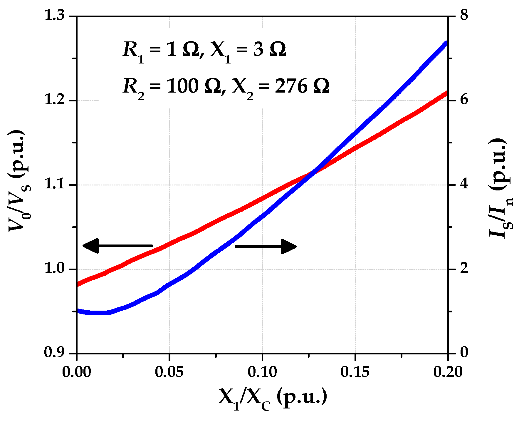
Let us define the resistance and reactance values of both grid and load, respectively. The output voltage and source current characteristics as a function of capacitance are shown in Figure 6. It can be seen from the figure that the current increase rapidly with the output voltage enhancement. The source current can enhance 6-8 times the nominal current in the distribution line. This phenomenon suggests the strict and careful measures for the selection of capacitance magnitude. Last but not least, it is concluded that the proposed method works fruitfully for the prevention of voltage instabilities in the distribution lines. However, simultaneous current amplification restricts both maximum voltage upsurge and time duration for the application of this method. Therefore, the proposed method can be applied together with the control of tap-changers.

4. Dynamic Process

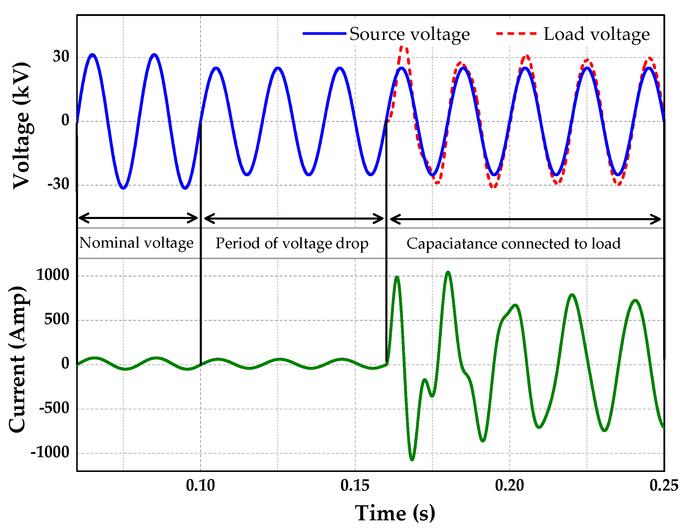
As stated above, the source current also increases with voltage amplification during capacitance’s connection with the load. It is suggested that the capacitance should be connected to the load for a duration of voltage drop and be disconnected as the transformation ratio changes to the desired level. The abrupt connection of capacitance to the load can cause a transient process. The transient process should be investigated and evaluated since it can decrease the quality of voltage supply and produce technical problems. The Laplace transform is applied to investigate the transient process, and it gives the following equation for V O ( s ) :
V O ( s ) [ 1 R 1   +   s L 1   +   1 R 2   +   1 s L 2   +   s C ]   =   V S ( s )   +   L 1 I S ( 0 ) R 1   +   s L 1 I L 2 ( 0 ) s   +   C V O ( 0 ) ,
where s is Laplace operator. Transformation and reduction of similar members in Equation (17) give us:
V O ( s ) = s 2 V O ( 0 ) C R 2 2 L 1 L 2 + s R 2 L 2 [ V S ( s ) + L 1 I S ( 0 ) L 1 I L 2 ( 0 ) + C R 1 V O ( 0 ) ] R 1 R 2 L 2 I L 2 ( 0 ) s 3 C R 2 L 1 L 2 + s 2 ( C R 1 R 2 L 2 + L 1 L 2 ) + s ( R 2 L 2 + R 1 L 2 + R 2 L 1 ) + R 1 R 2 ,
V s ( t )   =   V m sin ( ω t ) V s ( s )   =   V m ω s 2   +   ω 2
Equation (18) is the third-order characteristic Laplace equation as a function of s . The positiveness of all coefficient at denominators of Equation (18) determines only two possible variants. In the first variant, one is negative and two are complex numbers with negative real parts. The second variant has only three negative real numbers. Only the second situation is desirable (three negative roots) since the dynamic process will not have high-frequency oscillations diminishing the quality of voltage regulation. There are three negative roots if the determinant of a denominator in (18) is positive. The expression of a determinant for a cubic equation having coefficients a , b , c , and d correspondingly for s 3 , s 2 , s 1 , and s 0 [33] is:
Δ   =   4 b 3 d   +   b 2 c 2 4 a c 3   +   18 a b c d 27 a 2 d 2 > 0 ,
Substitution expressions of a , b , c , and d from (18) to (20) and following simplification yields a condition for three negative roots:
R 2 L 1 L 2 3   +   18 C R 1 R 2 2 L 1 L 2 4 R 1 L 1 L 2 4 C R 2 3 L 2 2 27 C 2 R 1 2 R 2 3 > 0 ,
It is possible to show that three negative roots exist in real situations almost always except very high capacitance or very low reactance ( X 2 ). Considering the real values of R 1 = 1 Ω, R 2 = 100 Ω, L 1 = 9 mH, L 2 = 899 mH (cosφ of a load equal to 0.94), maximum capacitance magnitude must be less than 5000 F for an oscillation-free solution. Such a conclusion guarantees smooth dynamic processes for most possible situations of using a method of capacitance connection to a load. Nevertheless, the actual behavior of voltage and current should be obtained in the development stage. Such a task is preferable to be done by a numeric approach considering the complication of the expression. Figure 7 shows the current and voltage modulations as a function of time during the transient process. It is observed that the source current increases with voltage enhancement.

5. Control Algorithm

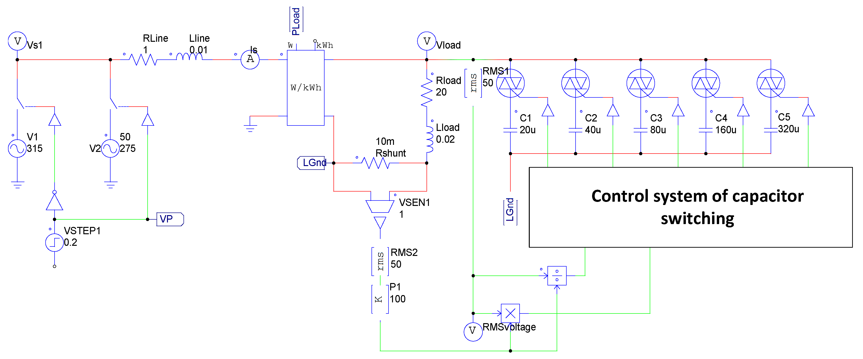
The control algorithm is required to connect/disconnect the capacitor during voltage instabilities in the grid. The model of distribution line connected with load and the proposed control algorithm was developed by PSIM software [34]. The schematic diagram of the model is represented in Figure 8. The simulation experiments were performed to verify the feasibility of the control algorithm for voltage stabilization.
The circuit of the model includes a control system, inductive load ( R load , L load ) with power factor 0.94, voltage supply, current sensor, power sensor, and bank of five capacitors ( C 1 - C 5 ) connected to the load through TRIACs. The voltage supply contains two sources one of with simulates nominal and another one a reduced under permissible level voltages. Voltage sources, modeling sub-station with tap-changer are connected to the load through the distribution line ( R line , L line ). Capacitors are arranged in a binary order of capacitance, the first one has a minimum required capacitance and each subsequent is two times higher than the previous one. In such an arrangement, the set of five capacitors provides a relative accuracy of 1/25 (~3.1%), which is enough for the control purpose in most of the practical events. The control system permanently measures the load voltage. In the case of voltage instabilities, the control system works in two steps. Firstly, the system calculates the required capacitance using Equation (14) to be added with the load. Further, the system determines which capacitors should be connected to the load by the following procedure. The required capacitance ( C r e q ) is divided by the capacitance C 5 , and is rounded to the nearest integer number lower than C r e q / C 5 . The residual number after the rounding is denoted as R 5 . In other words:
S 5   =   f l o o r C r e q C 5 ;   R 5   =   C r e q C 5 · S 5 ,
where f l o o r is the function that takes as input a real number and gives as output the greatest integer less than or equal to an initial number. This procedure is repeated five times. However, the C r e q is substituted by R 5 in Equation (22) and further from R 4 to R 2 :
C r e q   =   R 5 ,
S 4   =   f l o o r C r e q C 4 ;   R 4   =   C r e q C 4 · S 4 ,
S 1   =   f l o o r C r e q C 4 ,
Values of S 4 S 1 obtain only two possible integer numbers: one or zero. For each Sk equal to one the corresponding switches of matching capacitors should be closed. This way the required capacitance will be connected to the load for improving its voltage to the nominal magnitude.
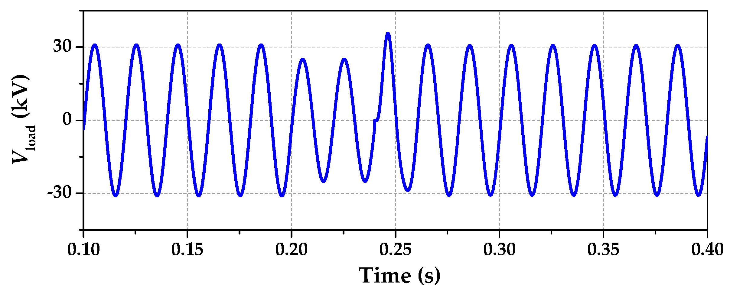
Figure 9 demonstrates the functionality of the control system to improve the voltage instabilities in the distribution line. The simulation results represent the load voltage at the end of distribution line before medium voltage transformer. It can be seen from the figure that the voltage decreases up to ~19% of the nominal level after the 0.2 sec during the load supply. At this moment, the control system recognizes a significant voltage drop and decides to connect a total capacitance of 225 μF. For this purpose, the capacitors C1, C2, and C4 are connected to the load and provided a total capacitance of 220 μF. As a result, the load voltage again increases up to the nominal magnitude within a short duration of time.
This study proves the possibilities to improve the voltage disturbances and maintain nominal load voltage using the connection of optimal capacitance in the distribution lines. It is important to note here that the load resistance should be higher than the resistance of a distribution line for voltage amplification effect, as a rule, hundreds of times more. More importantly, the voltage enhancement should remain in the maximum range of 15%–20% so that the source current stays in the allowable range. Higher voltage amplification can also be achieved, but only for a short period during which a tap-changer will be able to change the transformation ratio to the required value.

6. Conclusions

In summary, this article presents an efficient solution to the problem of voltage instabilities in power distribution lines. The application of capacitive reactive power to the load can efficiently prevent the voltage drop. The required voltage amplification is achieved by connecting appropriate capacitors at the load, and the capacitance values should be selected according to the impedance of a distribution line. The set of capacitors should be chosen in a binary manner of capacitance values for the simplicity of the control system. In such an arrangement, each sequential capacitance magnitude is two times larger than the previous one.
The substantial current enhancement in the distribution line during the capacitive power application should be taken into account. Therefore, the capacitive reactive power is applied for a short time such that the tap-changer is able to correct the transformation ratio. The dynamic process of voltage changes during the application of capacitive reactive power is also studied in this work. It is found that the dynamic process of voltage changes can be smoothed significantly if the capacitors are connected at the end or beginning of a voltage period.

Author Contributions

Conceptualization, M.A., S.R. and Ido.A.; methodology, M.S., I.A. (Ido Amiel), I.A. (Ilan Aharon), and M.A.; software, M.A., I.A. (Ilan Aharon); validation, I.A. (Ido Amiel), M.S. and S.R.; formal analysis and investigation, I.A. (Ido Amiel), M.S. and S.R.; resources, I.A. (Ido Amiel) and M.A.; data curation, I.A. (Ido Amiel) and S.R.; writing—original draft preparation, I.A. (Ido Amiel) and S.R.; writing—review and editing, S.R. and M.A.; supervision, M.A.; project administration, M.A. All authors have read and agreed to the published version of the~manuscript.

Funding

This research received no external funding.

Conflicts of Interest

The authors declare no conflict of interest.

Abbreviations and Nomenclatures

The following abbreviations and nomenclature are used in this manuscript:
PCCPoint of Common Coupling
DERDistributed energy sources
PVPhotovoltaic
Z C Consumer impedance
Z L V L Impedance of low voltage line
Z M V L Impedance of medium voltage line
Z H V L Impedance of high voltage line
R 1 Resistance of distribution line
X 1 Reactance of distribution line
R 2 Resistance of load
X 2 Reactance of load
V S Source voltage
V O Output voltage
I S Distribution line current
I R 2 Load active current
I X 2 Load reactive current
I C Capacitor current
I n Nominal current
λOutput voltage amplification
ηAmplification coefficient

References

  1. Wang, L.; Yan, R.; Saha, T.K. Voltage Management for Large Scale PV Integration into Weak Distribution Systems. IEEE Trans. Smart Grid 2018, 9, 4128. [Google Scholar] [CrossRef]
  2. Sorkin, O.; Farber, E.; Averbukh, M. Selecting Ultracapacitors for Smoothing Voltage Deviations in Local Grids Fed by Transformer with Tap-Changer and Distributed PV Facilities. Electronics 2019, 8, 357. [Google Scholar] [CrossRef] [Green Version]
  3. Rajput, S.; Averbukh, M.; Yahalom, A.; Minav, T. An Approval of MPPT Based on PV Cell’s Simplified Equivalent Circuit During Fast-Shading Conditions. Electronics 2019, 8, 1060. [Google Scholar] [CrossRef] [Green Version]
  4. Gayatri, M.; Parimi, A.M.; Kumar, A.P. A review of reactive power compensation techniques in microgrids. Renew. Sustain. Energy Rev. 2018, 81, 1030. [Google Scholar] [CrossRef]
  5. Ok, Y.; Lee, J.; Choi, J. Consideration of Reactor Installation to Mitigate Voltage Rise Caused by the Connection of a Renewable Energy Generator. Energies 2017, 10, 344. [Google Scholar] [CrossRef] [Green Version]
  6. Zhou, B.; Meng, L.; Yang, D.; Ma, Z.; Xu, G. A Novel VSG-Based Accurate Voltage Control and Reactive Power Sharing Method for Islanded Microgrids. Sustainability 2019, 11, 6666. [Google Scholar] [CrossRef] [Green Version]
  7. Ivanov, O.; Neagu, B.-C.; Grigoras, G.; Gavrilas, M. Optimal Capacitor Bank Allocation in Electricity Distribution Networks Using Metaheuristic Algorithms. Energies 2019, 12, 4239. [Google Scholar] [CrossRef] [Green Version]
  8. Molina, E.; Candelo-Becerra, J.E.; Hoyos, F.E. Control Strategy to Regulate Voltage and Share Reactive Power Using Variable Virtual Impedance for a Microgrid. Appl. Sci. 2019, 9, 4876. [Google Scholar] [CrossRef] [Green Version]
  9. Todescato, M.; Simpson-Porco, J.W.; Dörfler, F.; Carli, R.; Bullo, F. Online distributed voltage stress minimization by optimal feedback reactive power control. IEEE Trans. Control Netw. Syst. 2017, 5, 1467–1478. [Google Scholar] [CrossRef]
  10. Molina-García, Á.; Mastromauro, R.A.; García-Sánchez, T.; Pugliese, S.; Liserre, M.; Stasi, S. Reactive power flow control for PV inverters voltage support in LV distribution networks. IEEE Trans. Smart Grid 2016, 8, 447–456. [Google Scholar] [CrossRef] [Green Version]
  11. Safayet, A.; Fajri, P.; Husain, I. Reactive power management for overvoltage prevention at high PV penetration in a low-voltage distribution system. IEEE Trans. Ind. Appl. 2017, 53, 5786–5794. [Google Scholar] [CrossRef]
  12. Sarkar, M.N.I.; Meegahapola, L.G.; Datta, M. Reactive power management in renewable rich power grids: A review of grid-codes, renewable generators, support devices, control strategies and optimization algorithms. IEEE Access 2018, 6, 41458–41489. [Google Scholar] [CrossRef]
  13. Kraiczy, M.; Stetz, T.; Braun, M. Parallel operation of transformers with on load tap changer and photovoltaic systems with reactive power control. IEEE Trans. Smart Grid 2017, 9, 6419–6428. [Google Scholar] [CrossRef]
  14. Hung, D.Q.; Mishra, Y.; Walker, G. Reducing voltage fluctuations using DSTATCOMs and reactive power of PV inverters in a medium voltage distribution system. J. Eng. 2019, 2019, 5274. [Google Scholar] [CrossRef]
  15. Das, A.; Gupta, A.; Choudhury, S.R.; Anand, S. Adaptive reactive power injection by solar PV inverter to minimize tap changes and line losses. In Proceedings of the National Power Systems Conference (NPSC), Bhubaneswar, India, 19–21 December 2016; pp. 1–6. [Google Scholar]
  16. Dixon, J.; Moran, L.; Rodriguez, J.; Domke, R. Reactive power compensation technologies: State-of-the-art review. Proc. IEEE 2005, 93, 2144–2164. [Google Scholar] [CrossRef]
  17. Girshin, S.S.; Goryunov, V.N.; Kuznetsov, E.A.; Petrova, E.V. The model of electrical loads in the steady-state regime rating of electric grids with capacitive current compensation. In Proceedings of the IEEE 16th International Conference on Environment and Electrical Engineering (EEEIC), Florence, Italy, 7–10 June 2016. [Google Scholar]
  18. Zhou, X.; Wei, K.; Ma, Y.; Gao, Z. A Review of Reactive Power Compensation Devices. In Proceedings of the IEEE International Conference on Mechatronics and Automation (ICMA), Changchun, China, 5–8 August 2018; pp. 2020–2024. [Google Scholar]
  19. Ma, Y.; Huang, A.; Zhou, X. A review of STATCOM on the electric power system. In Proceedings of the IEEE International Conference on Mechatronics and Automation (ICMA), Beijing, China, 2–5 August 2015; pp. 162–167. [Google Scholar]
  20. Titus, M.G.G. Reactive power compensation using STATCOM for single phase distribution system. In Proceedings of the International Conference on Circuits, Power and Computing Technologies (ICCPCT-2015), Nagercoil, India, 19–20 March 2015. [Google Scholar]
  21. McGranaghan, M.F.; Zavadil, R.M.; Hensley, G.; Singh, T.; Samotyj, M. Impact of utility switched capacitors on customer systems-magnification at low voltage capacitors. IEEE Trans. Power Deliver. 1992, 7, 862. [Google Scholar] [CrossRef]
  22. Kusko, A.; Thompson, M.T. Power Quality in Electrical Systems; McGraw-Hill: New York, NY, USA, 2007. [Google Scholar]
  23. Popavath, L.N.; Kaliannan, P. Photovoltaic-STATCOM with Low Voltage Ride through Strategy and Power Quality Enhancement in a Grid Integrated Wind-PV System. Electronics 2018, 7, 51. [Google Scholar] [CrossRef] [Green Version]
  24. Lin, F.J.; Lu, K.C.; Ke, T.H.; Yang, B.H.; Chang, Y.R. Reactive power control of three-phase grid-connected PV system during grid faults using Takagi–Sugeno–Kang probabilistic fuzzy neural network control. IEEE Trans. Ind. Elect. 2015, 62, 5516. [Google Scholar] [CrossRef]
  25. Arshad, A.; Lehtonen, M. Instantaneous Active/Reactive Power Control Strategy for Flicker Mitigation Under High PV Penetration. In Proceedings of the IEEE PES Innovative Smart Grid Technologies Conference Europe (ISGT-Europe), Sarajevo, Bosnia-Herzegovina, 21–25 October 2018. [Google Scholar]
  26. Hasheminamin, M.; Agelidis, V.G.; Ahmadi, A.; Siano, P.; Teodorescu, R. Single-point reactive power control method on voltage rise mitigation in residential networks with high PV penetration. Renew. Energy 2018, 119, 504. [Google Scholar] [CrossRef]
  27. Jain, S.; Shadmand, M.B.; Balog, R.S. Decoupled active and reactive power predictive control for PV applications using a grid-tied quasi-Z-source inverter. IEEE J. Emerg. Sel. Top. Power 2018, 6, 1769. [Google Scholar] [CrossRef]
  28. Yang, D.; Wang, X.; Liu, F.; Xin, K.; Liu, Y.; Blaabjerg, F. Adaptive reactive power control of PV power plants for improved power transfer capability under ultra-weak grid conditions. IEEE Trans. Smart Grid 2017, 10, 1269. [Google Scholar] [CrossRef] [Green Version]
  29. Shagalieva, A.I.; Pershikov, G.A.; Lyulina, M.A.; Belyaev, A.N. Analytical investigation of AC transmission line operation with series compensation facilities. In Proceedings of the IEEE Conference of Russian Young Researchers in Electrical and Electronic Engineering (EIConRus), Moscow, Russia, 28–31 January 2019; pp. 1054–1059. [Google Scholar]
  30. Guiping, Z.; Xiaowei, D.; Chen, Z. Optimization of reactive power compensation of HVAC cable in off-shore wind power plant. IET Renew. Power Gener. 2015, 9, 857–863. [Google Scholar] [CrossRef]
  31. A 6 Analog Input Module for the MOSCAD-L RTU. Available online: https://www.motorolasolutions.com/content/dam/msi/docs/business/products/scada_products/moscad/_documents/static_files/moscad-l_6ai_module_specsheet_new.pdf (accessed on 12 December 2019).
  32. Pure Black Box-Handheld Power Quality Analyzer. Available online: https://www.elspec-ltd.com/metering-protection/power-quality-analyzers/purebb-power-quality-analyzer-handheld/ (accessed on 9 December 2019).
  33. Tignol, J.P. Galois’ Theory of Algebraic Equations; World Scientific Publishing Company: Singapore, 2015. [Google Scholar]
  34. PSIM-Software for Power Electronics. Available online: https://powersimtech.com/products/psim/ (accessed on 2 December 2019).
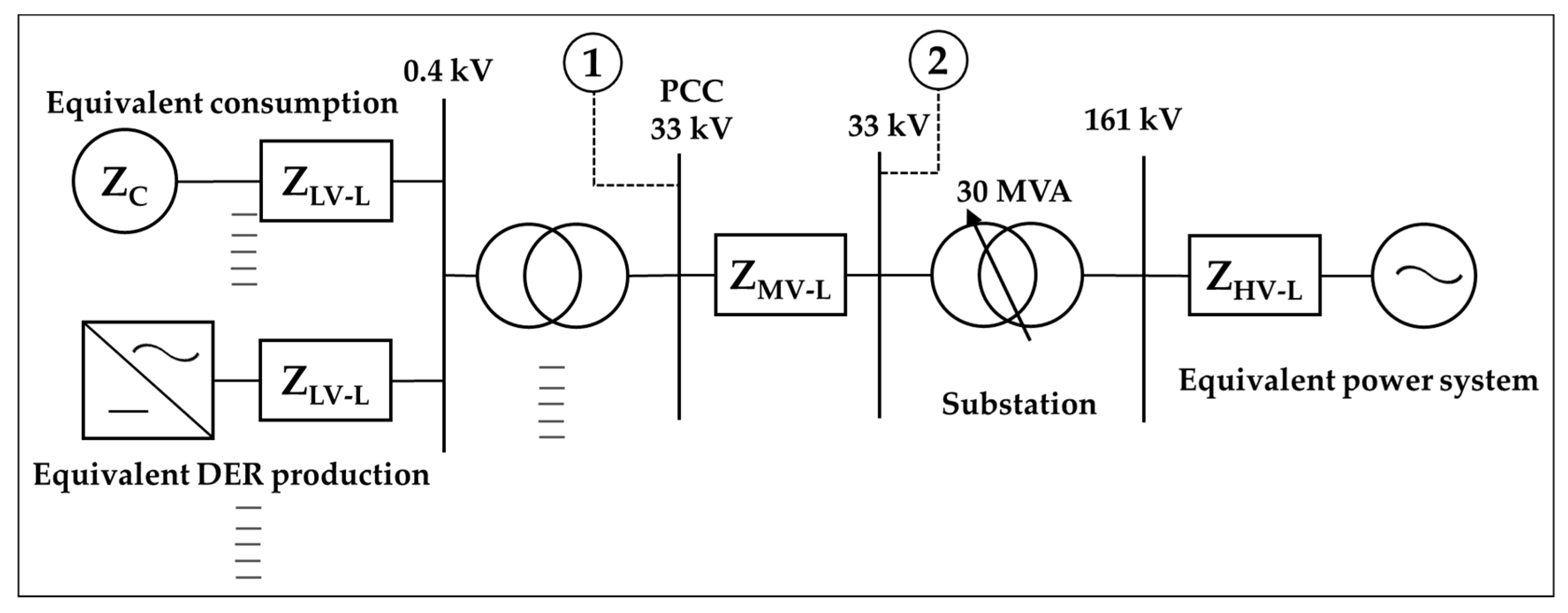
Figure 1. Single line diagram of the grid connected with renewable energy sources, e.g., solar plants. ( Z C : Consumer impedance, Z L V L : Impedance of low voltage line, Z M V L : Impedance of medium voltage line, Z H V L : Impedance of high voltage line, PCC: point of common coupling, DER: distributed energy sources). Points 1 and 2 are designated for measurements at PCC and substation respectively.
Energies 13 00875 g001
Figure 2. Voltage fluctuations in the typical 33 kV distribution line during the year (2019). The data is measured at both substation and PCC.
Energies 13 00875 g002
Figure 3. Functionality of the tap-changer in case of (a) voltage drop, and (b) voltage rise.
Energies 13 00875 g003
Figure 4. Lumped components model of a distribution line with a load and compensating capacitance with reactance ( X C ). The R 1 and X 1 are resistance and reactance of the distribution line, respectively. The R 2 and X 2 are resistance and reactance of load, respectively. The V S , V 0 , I S , I R 2 , I X 2 , and I C are the source voltage, output voltage, distribution line current, active load current, load reactive current, and capacitor current, respectively.
Energies 13 00875 g004
Figure 5. The ratio between output and input voltages as a function of reactance ( X C ).
Energies 13 00875 g005
Figure 6. Output voltage and source current as a function of capacitance.
Energies 13 00875 g006
Figure 7. Dynamic behavior of output voltage and current.
Energies 13 00875 g007
Figure 8. The block diagram for the proposed control system.
Energies 13 00875 g008
Figure 9. Load voltage as a function of time during a voltage drop and the application of the proposed method with the control system.
Energies 13 00875 g009