Article

Pulsating Flow of CNT–Water Nanofluid Mixed Convection in a Vented Trapezoidal Cavity with an Inner Conductive T-Shaped Object and Magnetic Field Effects

by
Ali J. Chamkha
1,
Fatih Selimefendigil
2,* and
Hakan F. Oztop
3
1
Department of Mechanical Engineering, Prince Sultan Endowment for Energy and Environment, Prince Mohammad Bin Fahd University, Al-Khobar 31952, Saudi Arabia
2
Department of Mechanical Engineering, Celal Bayar University, Manisa 45140, Turkey
3
Department of Mechanical Engineering, Technology Faculty, Firat University, Elazig 23119, Turkey
*
Author to whom correspondence should be addressed.
Energies 2020, 13(4), 848; https://doi.org/10.3390/en13040848
Submission received: 13 December 2019 / Revised: 9 January 2020 / Accepted: 9 January 2020 / Published: 14 February 2020
(This article belongs to the Section J: Thermal Management)

Abstract

:
Mixed convection of carbon-nanotube/water nanofluid in a vented cavity with an inner conductive T-shaped object was examined under pulsating flow conditions under magnetic field effects with finite element method. Effects of different parameters such as Richardson number (between 0.05 and 50), Hartmann number (between 0 and 30), cavity wall inclination (between 0 and 10 ), size (between 0.1 H and 0.4 H) and orientation (between −90 and 90 ) of the T-shaped object, and amplitude (between 0.5 and 0.9) and frequency (Strouhal number between 0.25 and 5) of pulsating flow on the convective flow features were studied. It was observed that the average Nusselt number enhanced with the rise of strength of magnetic field, solid nanoparticle volume fraction, and amplitude of the pulsation, while the effect was opposite for higher values of Ri number and cavity wall inclination angle. The presence of the T-shaped object and adjusting its size and orientation had significant impact on the main flow stream from inlet to outlet and recirculations around the T-shaped object and in the vicinity of hot wall of the cavity along with the magnetic field strength. Pulsating flow resulted in heat transfer enhancement as compared to steady flow case for all configurations. However, the amount of increment was different depending on the variation of the parameters of interest. Heat transfer enhancements were 41.85% and 20.81% when the size of the T-shaped object was increased from 0.1 H to 0.4 H. The T-shaped object can be utilized in the vented cavity as an excellent tool for convective heat transfer control. As highly conductive CNT particles were used in water, significant enhancements in the average Nusselt number between 97% and 108% were obtained both in steady flow and in pulsating flow cases when magnetic field was absent or present.

1. Introduction

The convection in vented cavities play a vital role in ventilating systems, food processing applications, electronic cooling, and many others. In heat transfer, many active and passive methods are used to control the convection in cavities. In this context, Saeidi and Khodadadi [1] examined the forced convection in a vented cavity with finite volume method. Different locations of the outlet ports were examined for Reynolds number between 10 and 500. Houshang et al. [2] examined the convective heat transfer features in mixed regime using a source while the study iswasperformed for Reynolds number between 50 and 1000 and the Richardson number is varied between 0 and 10. Convection in a ventilated cavity for the mixed regime with an isothermal vertical wall was performed numerically by Angirasa [3]. Heat transfer was observed to rise with higher effects of forced flow at lower values of Grashof number while for higher values of it the interaction became complicated.
Conducting or adiabatic solid bodies can be inserted into the vented cavity system to control the fluid flow and convective heat transfer features. In the literature, simple obstacle shapes such as stationary or rotating circular cylinders [4,5,6,7,8,9] and rectangular [10,11,12,13] and triangular [14,15] shaped bodies are used in cavities or channels in convection related studies. The size, location, and thermal conductivity of the body are important factors for convective heat transfer enhancement. If the body is rotating, direction and amplitude of the rotating object become important. However, as opposed to simpler objects, an L-shaped or a T-shaped conductive obstacle has more potential to generate re-circulations near the object and influence the main flow in the cavity; therefore, fluid flow and heat transfer characteristics can be altered. Pulsating flow is utilized in many thermal systems [16,17,18,19,20,21]. As the flow pulsation is promoted, thermal boundary layers along the hot surfaces become interrupted and heat transfer features are altered. Depending on the pulsating amplitude and frequency and geometry of the thermal system configuration, the heat transfer can be increased or deceased.
Influences of magnetic field may be observed in various practical engineering applications such as in glass float, geothermal energy extraction, and many others. In heat transfer engineering, impacts of magnetic field may be utilized for control of convection. In many applications, such as in convection within cavities, effects of magnetic field were found to reduce the effective convection [22,23,24,25]. However, in some recent studies, these effects were found to suppress the fluid recirculation in separated flows such channel flow with sudden area expansion or flow in a cavity with vented ports [26]. Influences of magnetic field were also considered in jet flow application in [27] and reduction in the unsteady effects was observed with higher magnetic field strength. In recent studies, magnetic field effects were used with nanofluids [28,29,30,31,32,33,34]. This technology of adding nano-sized particles into the heat transfer fluid was successfully used in many applications including solar power, refrigeration, and convective heat transfer [35,36,37,38,39,40,41,42,43,44].
In a recent benchmark study, nanofluid behavior and heat transfer using computational fluid dynamics (CFD) tools were compared with experimental works [45]. It was observed that the CFD can predict the convection features using the nanofluid as heat transfer fluid. Many different particles can be used in applications, but in recent years the use of highly conducive carbon nanotubes (CNTs) is growing [46,47,48,49,50]. They provide significant heat transfer enhancements [51,52,53].
In this study, magneto-hydrodynamics (MHD) mixed convention in a ventilated cavity under pulsating flow conditions were examined in the presence of a conducive T-shaped obstacle within the cavity. The complicated nature of occurrence of multiple recirculation regions and coupling of thermo-fluid interactions with natural convection effects and other effects such as magnetic field and solid conducting body within the system makes those systems very hard to treat theoretically. Therefore, numerical simulations were used to perform such a study. In the literature, there are a few studies that deal with the application of pulsating flow with magnetic field effects [54,55,56]. The novelty of the study can be listed as below: (i) It included a conductive T-shaped object within the cavity, which can generate many vortices near the object and affect the heat transfer features. (ii) Magnetic field effects were used in the vented cavity with flow pulsation effects. Even though there are some studies with the pulsating flow in vented cavities, the use of magnetic field, which has the potential to redistribute the separated flow regions within the vented cavity, adds novelty and the method has many control parameters and applicability for many thermal engineering systems, as mentioned above. (iii) Highly conductive CNT nanoparticles were used with water and heat transfer rates were expected to enhance significantly. (iv) The cavity had a trapezoidal shape, which includes geometrical complexity and effects of side wall inclination angles were considered.
Numerical results from this study can be beneficial when designing and optimizing thermal configurations related to vented cavities, which have many heat transfer engineering applications, as discussed above.

2. Numerical Configuration

2.1. Model Description

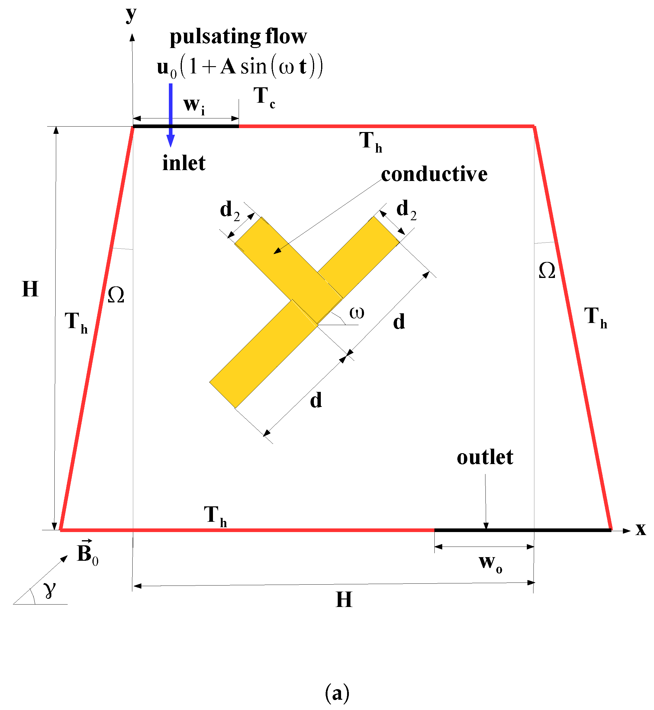
Nanofluid mixed convection within a trapezoidal shaped vented cavity with an inner conductive T-shaped obstacle was analyzed considering the effects of magnetic field and pulsating flow. Figure 1 shows the physical problem with boundary conditions. The cavity height is H, while the sizes of the inlet and outlet ports are w i = w o = 0.25 H . Nanofluid with cold temperature enters the inlet of the vented cavity with velocity of u = u 0 1 + A sin ( ω t ) and temperature of T = T c . The cavity is trapezoidal with side wall inclination angles of Ω . W 1 (left wall), W 2 (bottom wall), W 3 (right wall), and W 4 (top wall) denote different hot wall segments of the configuration. A T-shaped conductive object was placed in the cavity with thermal conductivity of k p . d, d 2 , and ω represent the half length, height, and inclination of the T-shaped object, respectively. d 2 was fixed to d 2 = 0.075 H during the simulation. The mid point of the bottom wall of the T-shaped object is placed at ( 0.5 H , 0.5 H ) within the cavity, which denotes the object location. Magnetic field is uniform and γ denotes the inclination angle. A single-walled carbon nanotube/water nanofluid was considered. The Prandtl number is 6.9 for the base fluid. The flow is 2D and laminar while Newtonian and incompressible fluid assumptions were utilized. Impacts of induced magnetic field, joule heating effects, and displacement currents were not considered. The density variation in the buoyancy was modeled by using the Boussinesq approximation. Thermal radiation effect with viscous dissipation effects were also considered to be negligible.

2.2. Model Equations and Boundary Conditions

The following parameters were used non-dimensionalize the governing equations:
X = x H , Y = y H , U = u u 0 , V = v u 0 , P = p ρ f u 0 2 , θ = T T c T h T c , τ = t u 0 H , Pr = ν f α f , Ha = B 0 H σ f μ f , Re = u 0 H ν f , St = f H u 0 Gr = g β f ( T h T c ) H 3 ν f 2 , Ri = Gr Re 2 , K r = k s k f .
Non-dimensional governing equations in 2D for unsteady, laminar, and two-dimensional flow are written as [57]:
U X + V Y = 0
U τ + U U X + V U Y = ρ f ρ n f P X + ν n f ν f 1 Re 2 U X 2 + 2 U Y 2 + ρ f ρ n f σ n f σ f Ha 2 Re V sin ( γ ) cos ( γ ) U sin 2 ( γ )
V τ + U V X + V V Y = ρ f ρ n f P Y + ν n f ν f 1 Re 2 V X 2 + 2 V Y 2 + + ρ f ρ n f σ n f σ f Ha 2 Re U sin ( γ ) cos ( γ ) V cos 2 ( γ ) + β n f β f Ri θ
θ τ + U θ X + V θ Y = 1 Re Pr k n f k f ( ρ c p ) f ( ρ c p ) n f 2 θ X 2 + 2 θ Y 2
Boundary conditions in non-dimensional form are written as:
  • For inlet port, V = 1 + A sin ( 2 π St τ ) , U = 0 , θ = 0 .
  • For outlet port, U Y = 0 , V = 0 , θ Y = 0 .
  • For the walls of the channel, U = V = 0 , θ = 1 .
  • On the walls of the T-shaped object, U = V = 0 .
  • At the interface between the fluid and solid domain (T-shaped object), θ n f = K r θ n s .
In the pulsating flow configuration, Nusselt number is time dependent. Local Nusselt number is obtained as:
Nu s , t = k n f k f θ n s .
where s and t are coordinate along the hot wall and time. Heat transfer enhancement (HTE) is defined by using the Nusselt number values in pulsating flow and steady flow cases as:
HTE = max ( Nu s m , p u l s a t i n g ) Nu m , s t e a d y Nu m , s t e a d y × 100 ,
where the sub-indices s m and m denote the spatial average in pulsating flow and mean value in steady flow, respectively.

2.3. Nanofluid Property Relations

In the current study, single-walled carbon nanotubes (SWCNT) were used in water. The density, thermal expansion coefficient, and specific heat of the nanofluid are described as:
ρ n f = 1 ϕ ρ f + ϕ ρ C N T
ρ β n f = 1 ϕ ρ β f + ϕ ρ β C N T
ρ C p n f = 1 ϕ ρ C p f + ϕ ρ C p C N T
Thermal conductivity of nanofluid is given as [50]:
k n f k f = ( 1 ϕ ) + 2 ϕ k C N T k C N T k f ln k C N T + k f 2 k f ( 1 ϕ ) + 2 ϕ k f k C N T k f ln k C N T + k f 2 k f .
In the above given representation, the space distribution effects of the carbon nanotubes are taken into account. This model gives very accurate results when compared with the experimental data, even at high particle volume fractions. In the work of Jiang et al. [58], a model for the carbon nanotubes aggregate is proposed. The temperature was found to have small impact on the thermal conductivity enhancement while the nonlinear enhancement of thermal conductivity with solid nanoparticles volume fractions was detected.
The Brinkman model was utilized for the viscosity of the nanofluid [59]:
μ n f = μ f ( 1 ϕ ) 2.5
This model for the viscosity was used in many studies for CNT–water heat transfer fluid [60,61,62]. In the study of Halelfadl et al. [63], the effects of solid volume fraction of nanoparticles and temperature on the viscosity of carbon nanotubes are considered for particle volume fraction of 0.0055% and 0.55%. No temperature dependence of the viscosity of the nanofluid was detected at high shear rate.

2.4. Solver Method and Code Validation

The above given governing equations were solved with Galerkin weighted residual method considering the appropriate boundary and initial conditions. In the method, the weak form of the equations are obtained. Approximations of flow variables with triangular Lagrange finite elements of different orders are performed. Residuals are established by substituting the approximations into the governing equations and weighted average of this residual is set be be zero as:
Ω W R d Ω = 0 .
The weight function is denoted by W. Newton–Raphson method was utilized for the solution of the nonlinear set of algebraic equations. For the time dependent part of the problem, variable-order backward differentiation scheme (BDF) was used with order of 1. Convergence criteria of 10 6 was set for the relative error.
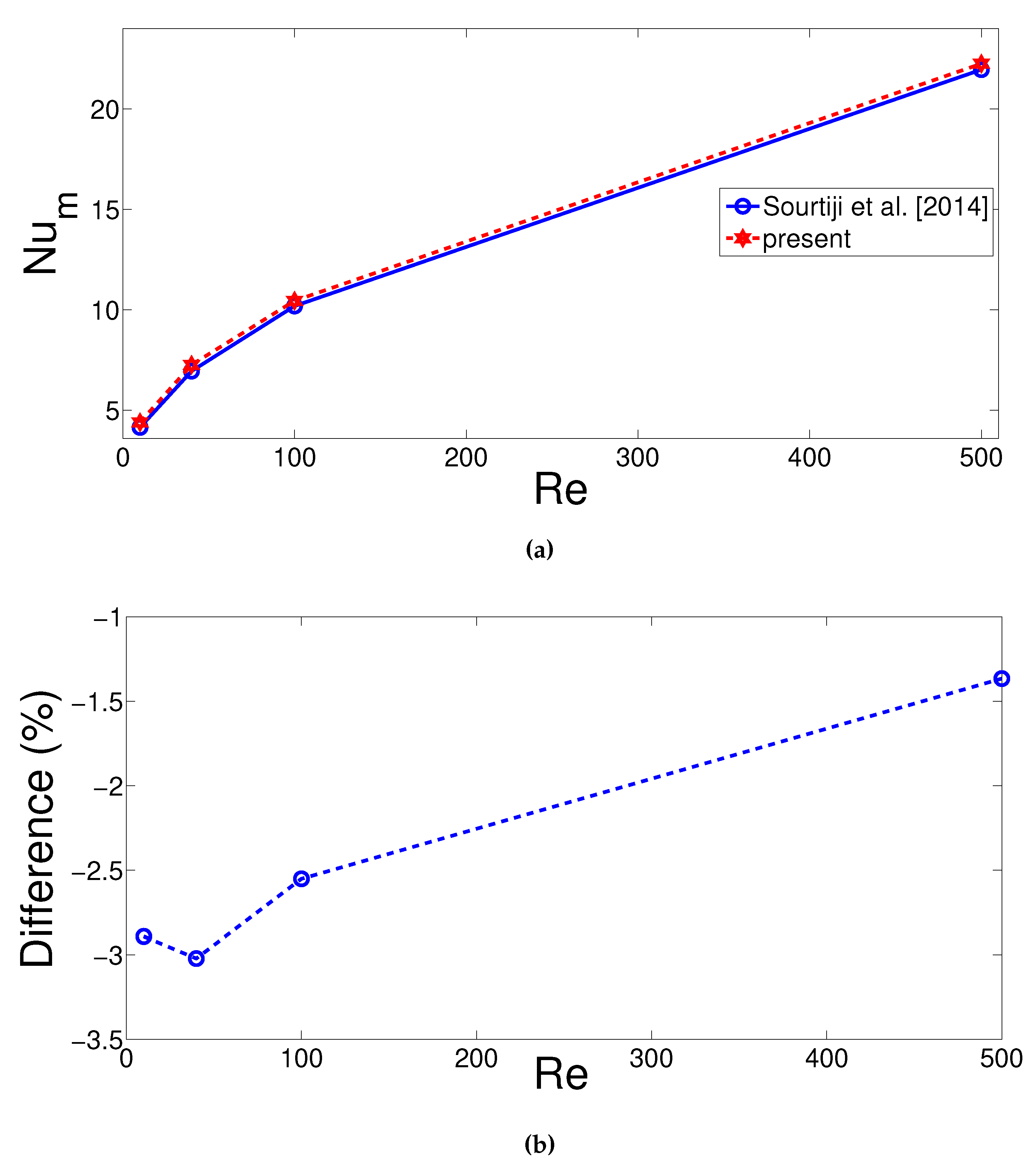
To assure mesh independence, numerical simulation tests with different grid sizes are performed. The grid was very fine towards the walls of the cavity and in the vicinity of interface between the solid and fluid domains while Figure 1b shows the mesh distribution. Table 1 shows the results of grid independence studies for various values of Ri and Ha number combinations considering all hot walls of the cavity for fixed values of Ri = 1, Ha = 10, Ω = 10 , ω = 45 and d = 0.15 H . Grid type G4 with 12,814 elements was used. Then, 1/50 of the period of oscillation ( P e r ) was chosen as the time step ( Δ t ) for the unsteady calculations. Validation was performed by using different available studies in the literature. In the first validation study, the results of Sourtiji et al. [64] were utilized where mixed convective heat transfer in a vented cavity with different locations of the outlet port was examined. The companion results of average Nu versus Reynolds number for Ri number of 10 is shown in Figure 2. The difference in percentage in Figure 2b was defined as the discrepancy of the reference average Nu values obtained by Sourtiji et al. [64] as compared to average Nusselt numbers obtained with the present code. In another validation, magnetic field effects for the free convection in a square cavity were used [65] and Table 2 gives the average Nusselt number comparison results considering various values of Rayleigh number when Hartmann number is fixed to 30. The highest deviation was seen for Ra = 10 7 and the value is −1.34%. The present solver is capable of solving problems in vented cavity with magnetic field effects.

3. Results and Discussion

Pulsating flow in a vented trapezoidal cavity with a T-shaped conductive obstacle was examined under the effects of a uniform magnetic field. The side wall of the vented cavity was also considered to be as inclined. The size and inclination of the object were used to control the flow re-circulation within the cavity and thus heat transfer characteristics were altered in pulsating flow conditions. The impacts of magnetic field were shown to be effective in the vented cavity and in application with separated flow in various studies. The impact of different parameters such as Richardson number (between 0.05 and 50), Hartmann number (between 0 and 30), side wall inclination of the vented cavity (between 0 and 10), size (between 0.1 H and 0.4 H) and orientation (between −90 and 90) of the conductive object, pulsating flow amplitude (between 0.5 and 0.9) and frequency (Strouhal number between 0) on the fluid flow, and convective heat transfer features were examined.

3.1. Effects of Richardson Number

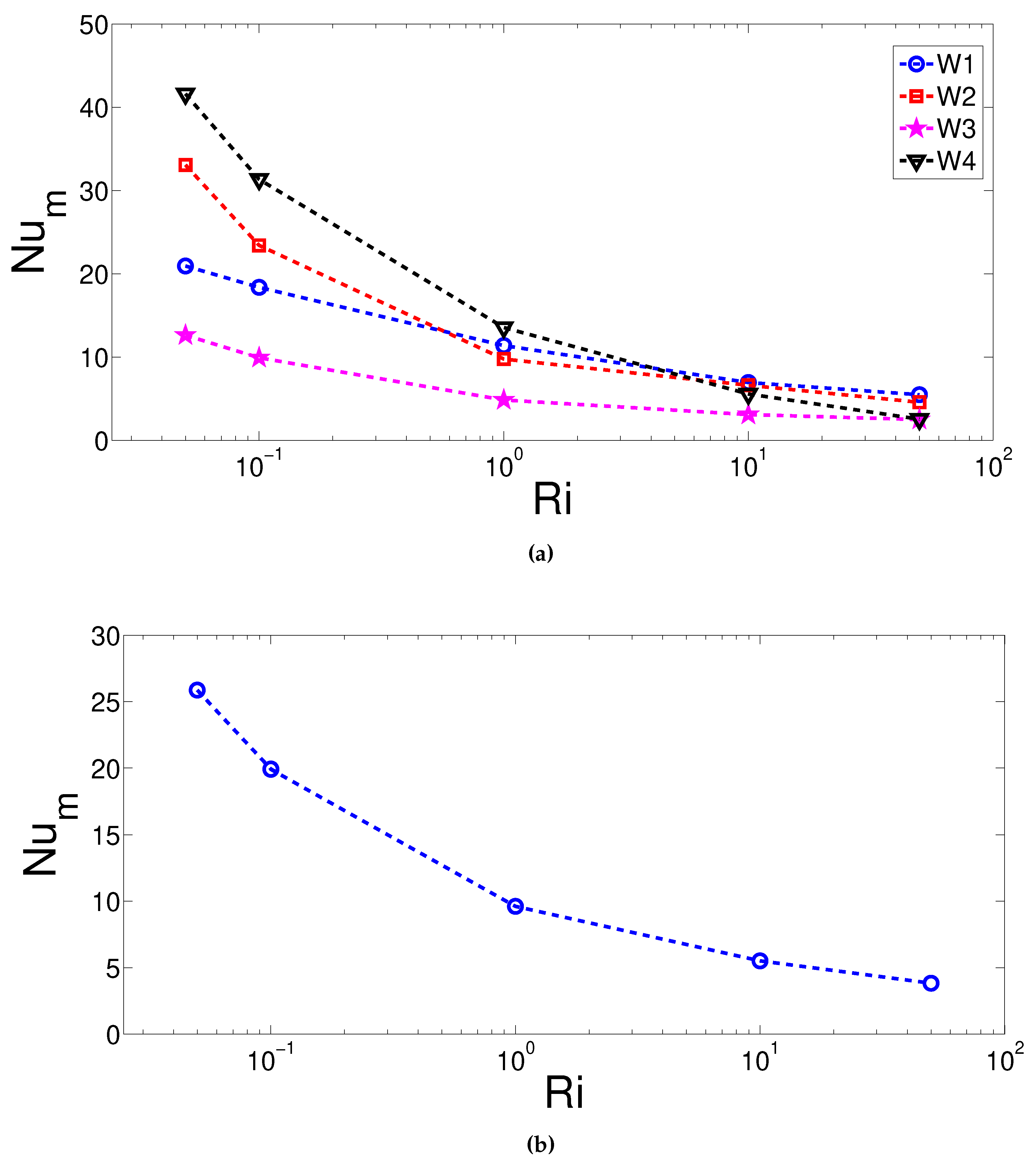
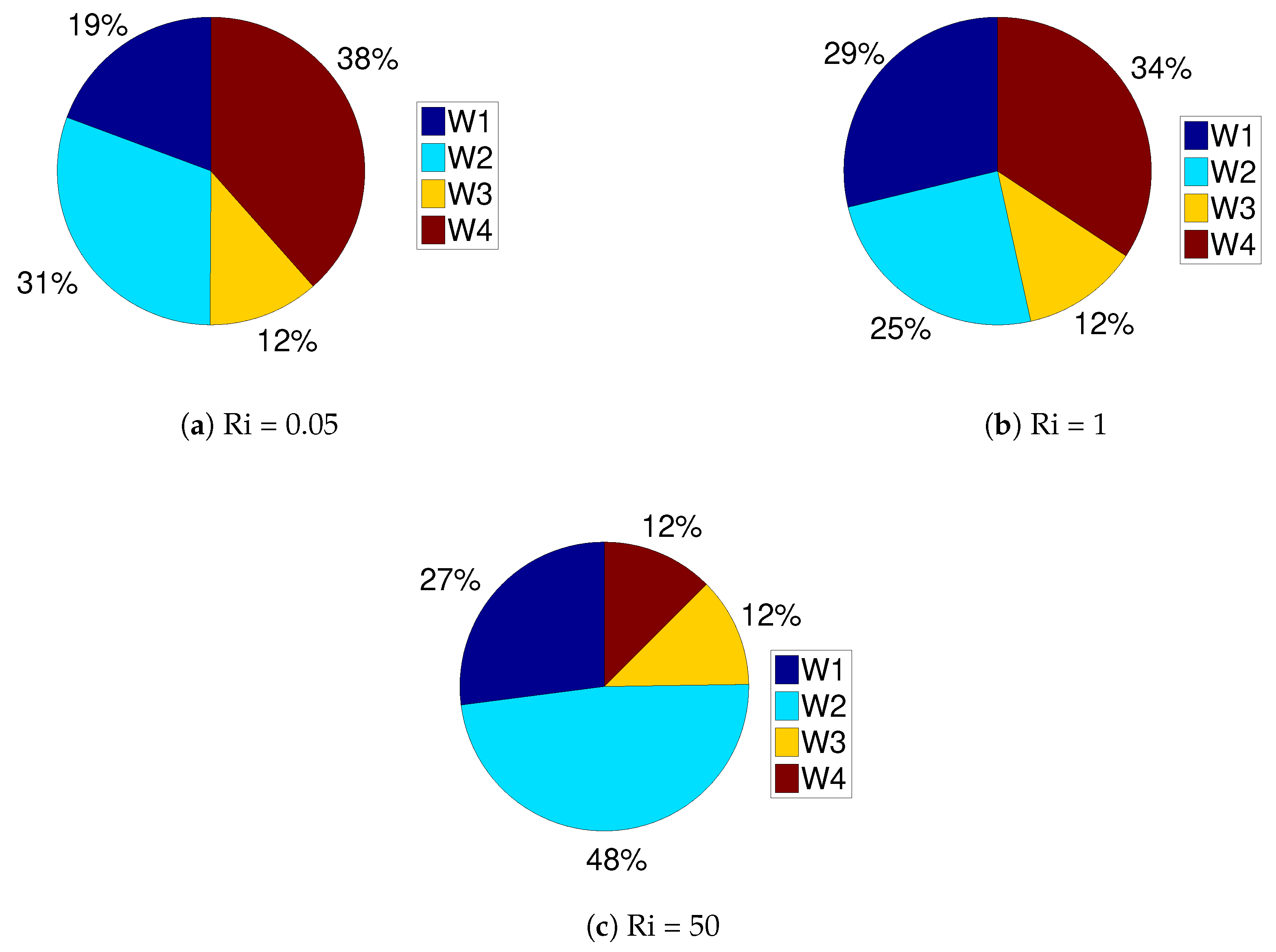
Impact of Ri number on the flow and thermal patterns are shown in Figure 3. A lower value Ri number gives a higher velocity of the incoming fluid since the Rayleigh number was fixed to Ra = 10 5 in the simulations. Multiple re-circulations were established in the cavity and near the T-shaped object. As the value of Ri number was increased, vortices near the T-shaped object first disappeared at Ri = 1 and then enlarged in size for Ri = 50. The extent of the vortex below the inlet port increased at Ri = 50, where forced convection effects were weak. Temperature gradients near the hot walls decreased with higher values of Ri number since less fluid flow energy was introduced. This effect was more pronounced near the upper and right hot wall segments of the vented cavity. The average Nusselt number versus Richardson number showed a decreasing trend for individual walls and all walls while different hot wall parts’ contributions to the overall Nu were different, as shown in Figure 4 and Figure 5. When cases with the maximum and minimum values of Richardson number were compared, the highest reduction in the contribution was seen for wall W4 (upper hot wall), which is 28%.
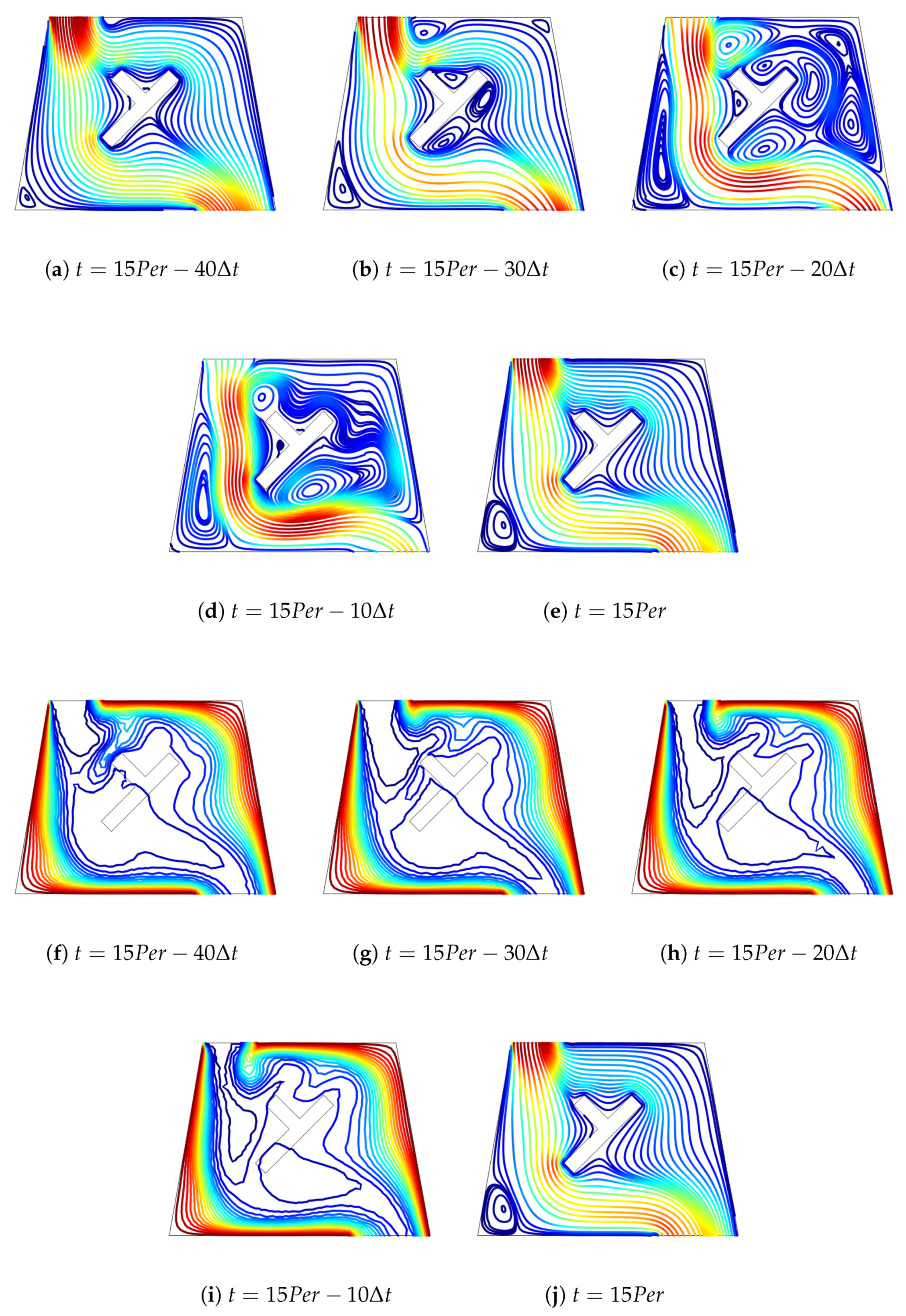
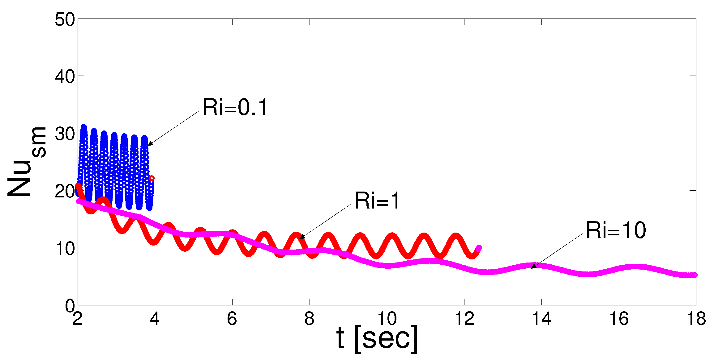
In pulsating flow conditions, variation of streamlines and isotherms are shown in Figure 6 for Richardson number of 1 considering various values of time instances within a period of the flow pulsation. Fifty time steps were used for one period of oscillation, Δ t = P e r 50 . The time dependent simulations were performed for 15 periods (15 P e r ) of pulsating flow. Appearance and disappearance of corner vortex below the inlet port, near the upper wall, and in re-circulation zones in the vicinity of the T-shaped object were seen in the cavity for various time instances of pulsating flow. Spatial average Nusselt number considering all of the hot walls showed periodic variation for different Ri values and highest values were attained for higher Richardson number (Figure 7). Strouhal number, which is a non-dimensional frequency based on the velocity of the incoming fluid, was fixed and thus the frequency of oscillation was higher for lower Ri number where velocity was higher. Comparison of the Nusselt numbers in steady flow and pulsating flow (highest value of the space average Nu) for different Ri numbers are shown in Table 3. Heat transfer enhancement with pulsating flow was obtained for all Ri numbers but enhancement was highest for lower Ri value, which is 46.5%.

3.2. Magnetic Field Effects

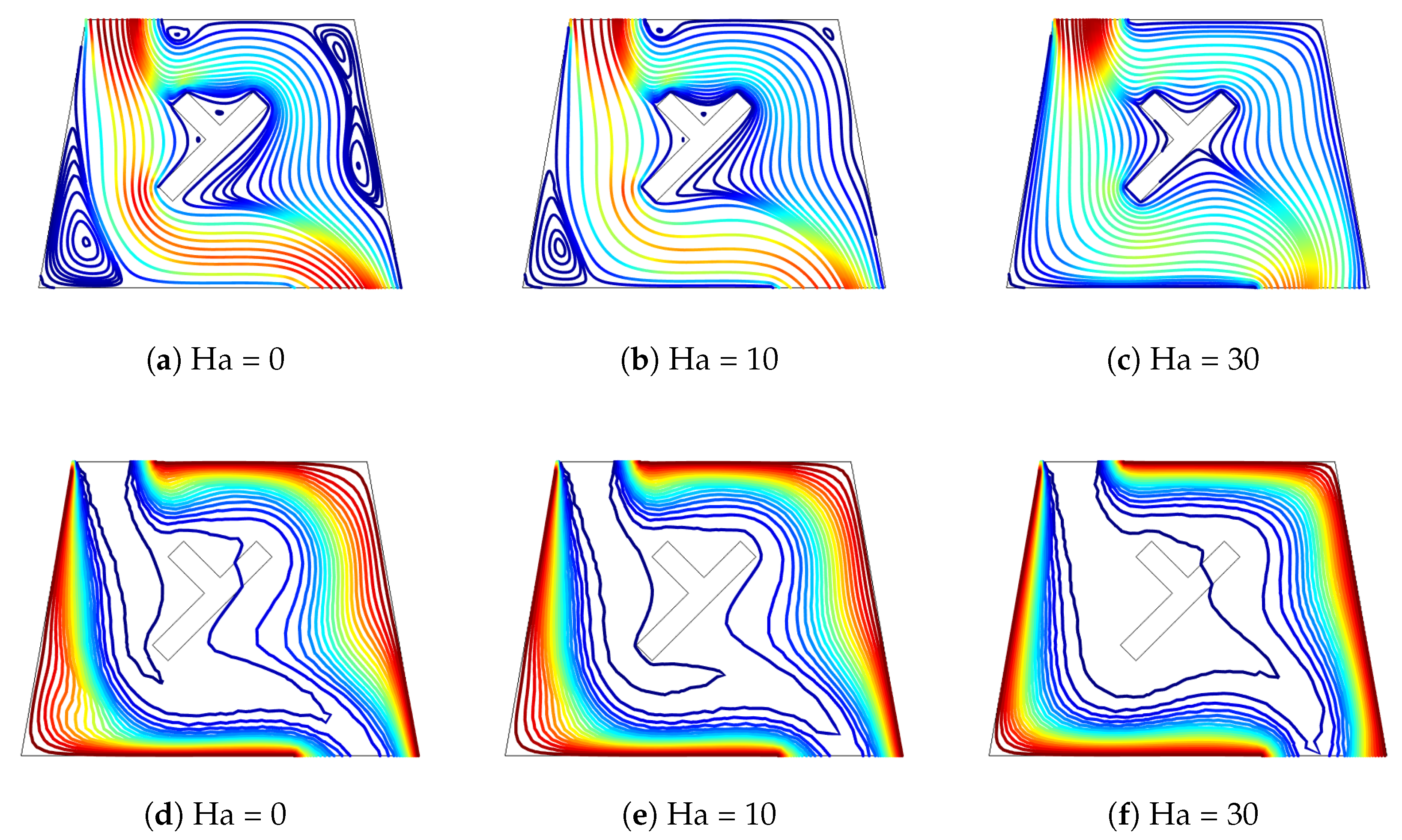
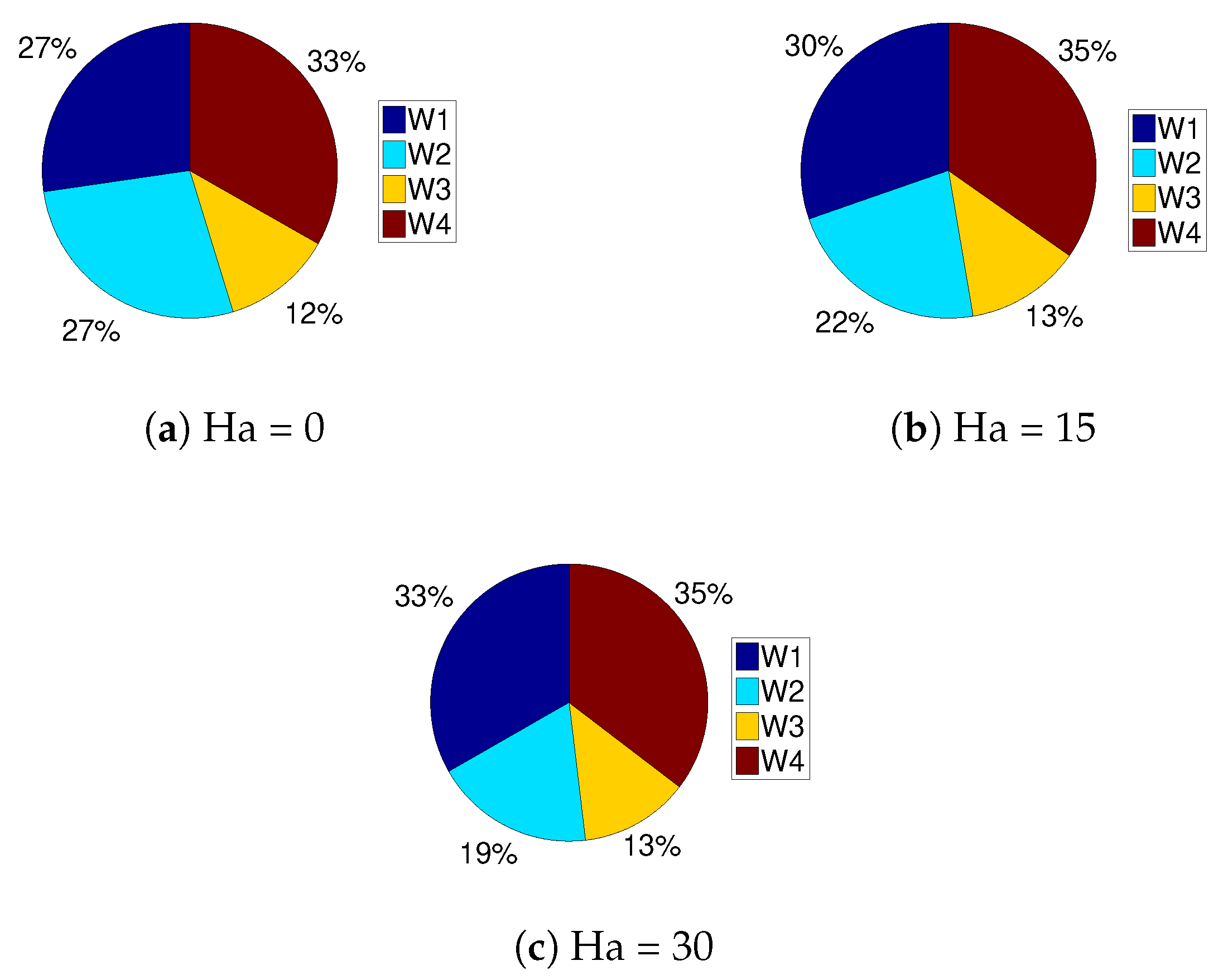
Effects of strength of uniform magnetic field on the variation of streamlines and isotherms in steady flow configuration are shown in Figure 8. In the absence of magnetic field, re-circulations near the left bottom and top right corner were formed in the vented cavity. As the strength of uniform magnetic field was increased, re-circulations in the cavity were suppressed but the fluid motion dampened as well. Clustering of the isotherms with magnetic field, especially for hot walls W1, W3 and W4, were apparent, as shown in Figure 8d–f. Average Nusselt number for those walls enhanced with magnetic field strength, as shown in Figure 9, while a reduction in the average Nusselt number was seen only for hot wall W2. The average heat transfer when taking into account all hot wall parts of the vented cavity enhanced with higher values of Hartmann number. Different hot wall segments contributed differently to the overall heat transfer rate, as shown in Figure 10. The contribution of wall W2 decreased while other wall contributions enhanced for higher Ha values.
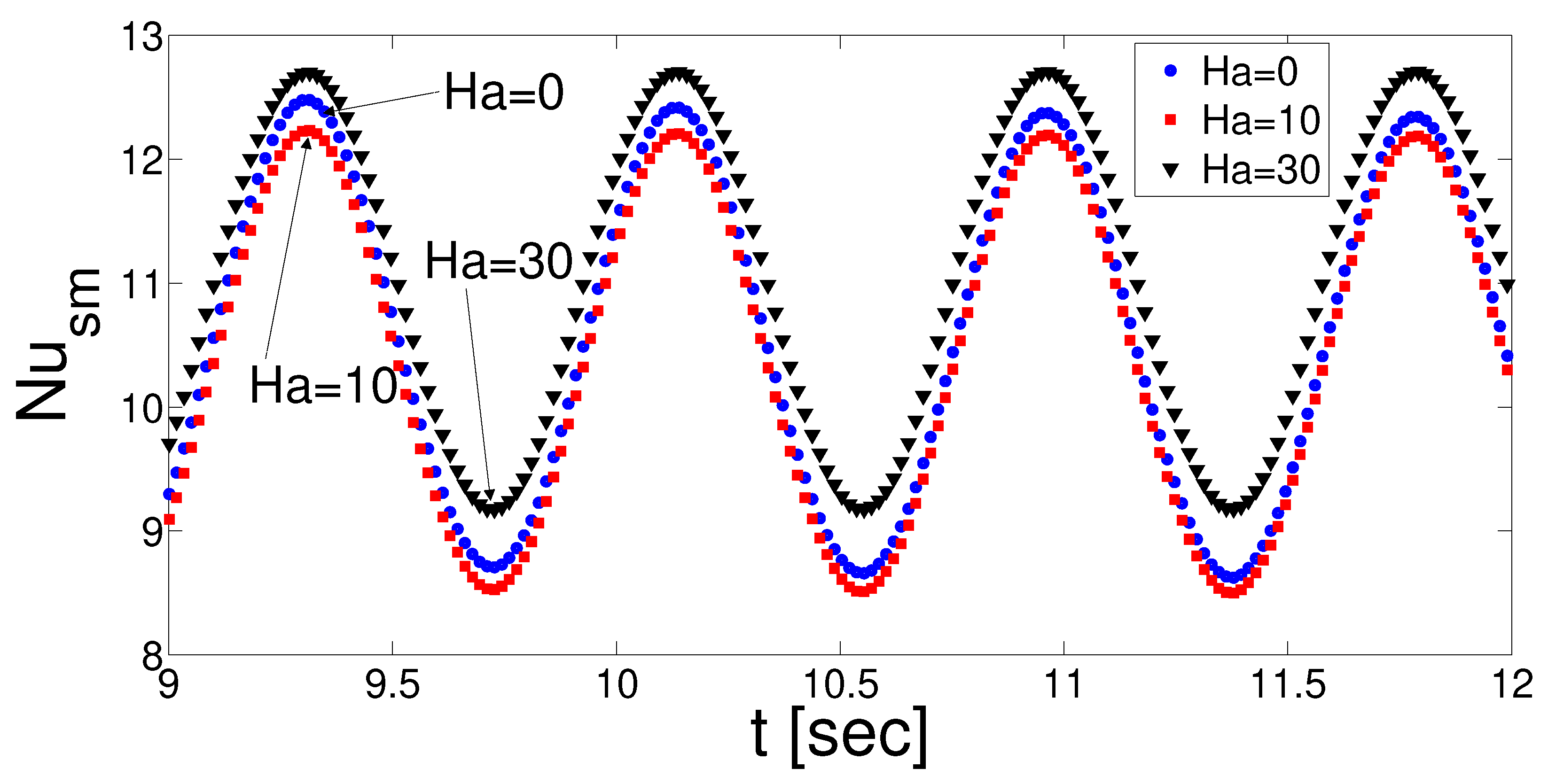
Suppression of the vortices were also seen in pulsating flow condition when magnetic field was imposed, as shown in Figure 11. The effect was influential in the cavity, expect for the regions near the T-shaped object. There were some slight variations in the spatial averaged Nusselt numbers for different magnetic field strengths, as shown in Figure 12. Enhancement of average heat transfer was seen with pulsating flow case, as shown in Table 4. There were some slight variations between the average Nu values for different Hartmann numbers in pulsating flow. However, HTE was reduced with higher values of Ha number and this could be attributed to the increment of the average Nu with magnetic field strength in the pulsating flow configuration.

3.3. Impact of Side Wall Inclination of the Vented Cavity

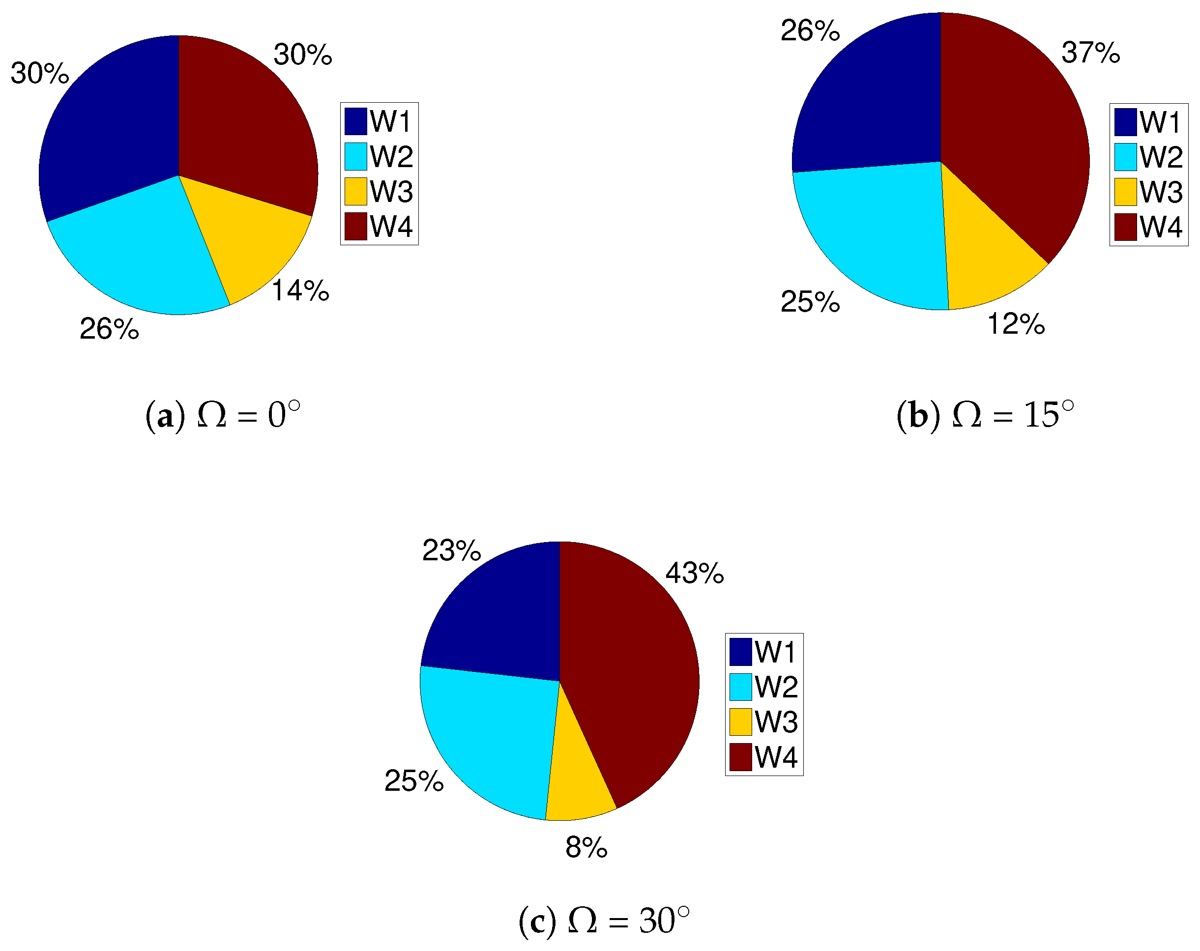
As the value of the inclination angle increased, vortices were established near the inclined surfaces below the inlet port and above the outlet port, as shown in Figure 13. Isotherms became less clustered in the regions where elongation of the walls took place and vortices were formed. The average heat transfer rate reduced for all walls except for hot wall W4 (top wall) with higher values of side wall inclination angles. Overall, the average Nu number was reduced for higher values of side wall inclination angle (Figure 14). Contributions of walls W1, W2 and W3 reduced with higher Ω while the impact was reversed for wall W4 and the increment was the contribution to the overall heat transfer rising by about 13% when minimum and maximum values of Ω were compared, as shown in Figure 15.
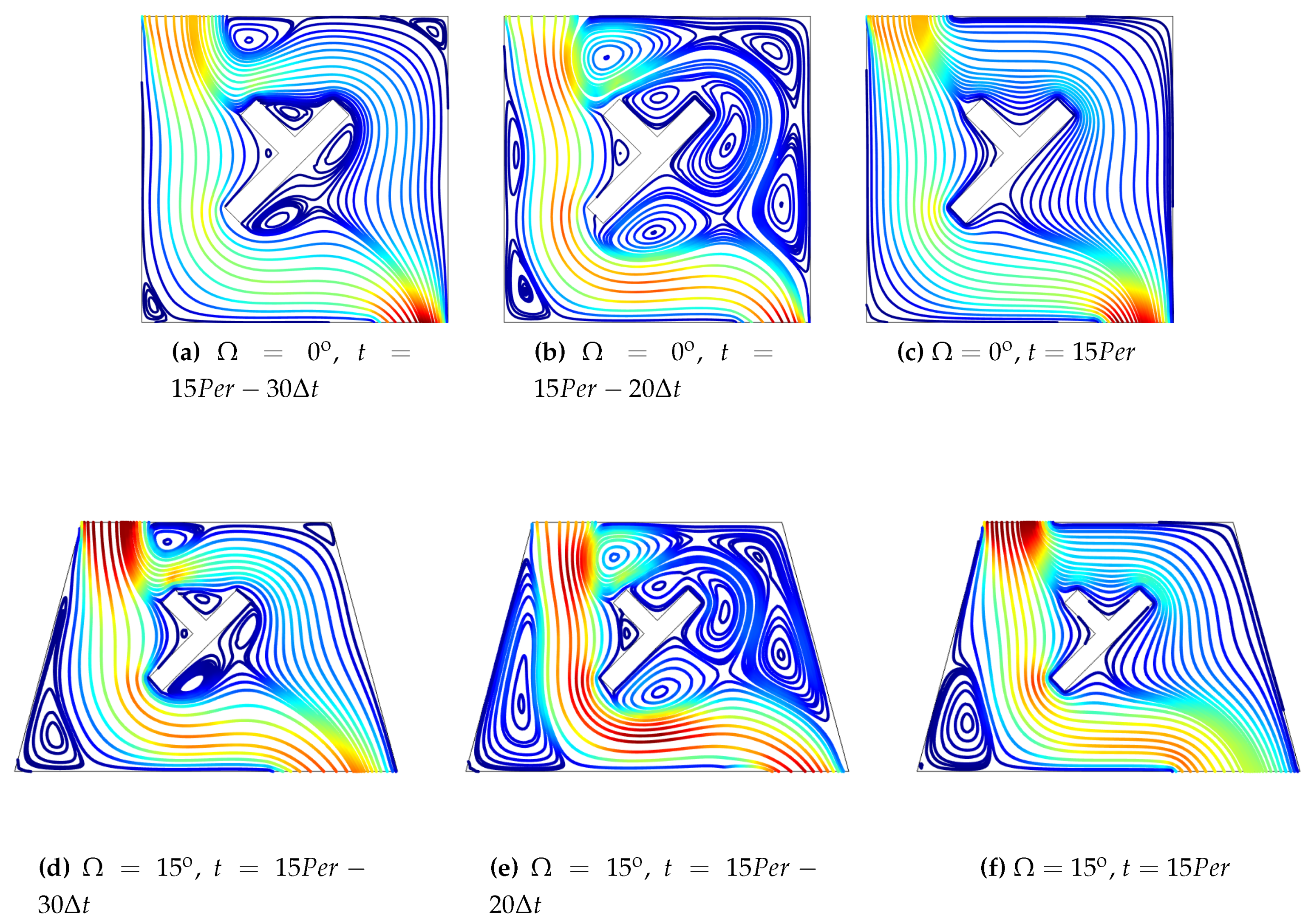
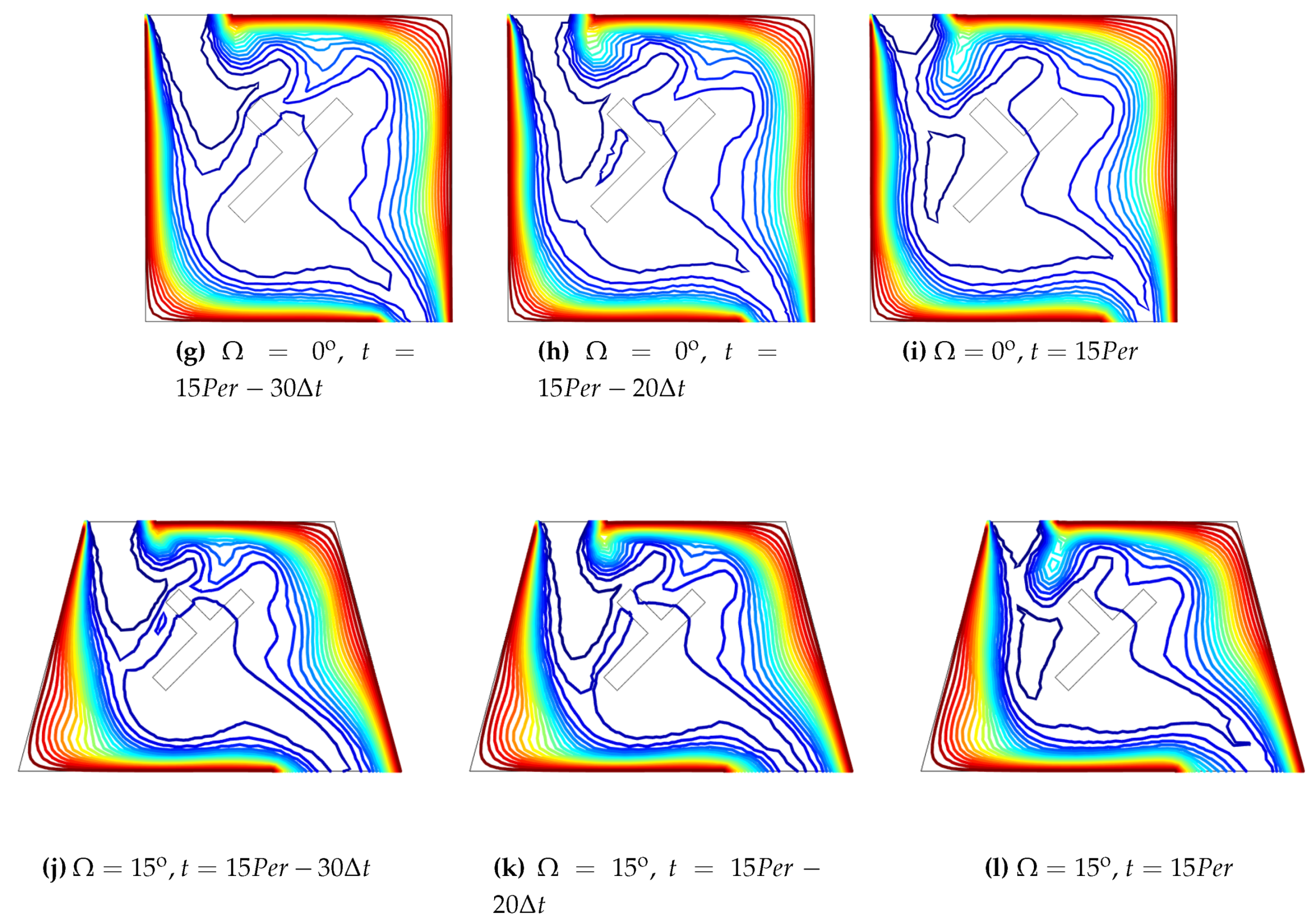
In pulsating flow, similar to steady flow configuration, vortices near the inclined walls were established and multiple re-circulation zones were also seen with different time instances within a period of flow pulsation (Figure 16). Spatial average and total average heat transfer reduced with higher values of Ω (Figure 17). Similar to previous configurations with flow pulsations, heat transfer enhanced as compared to steady flow configuration and therefore HTE rose from 21 to 48 when Ω was varied from 0 to 30 in pulsating flow conditions.

3.4. Effects of Conducive T-shaped Obstacle

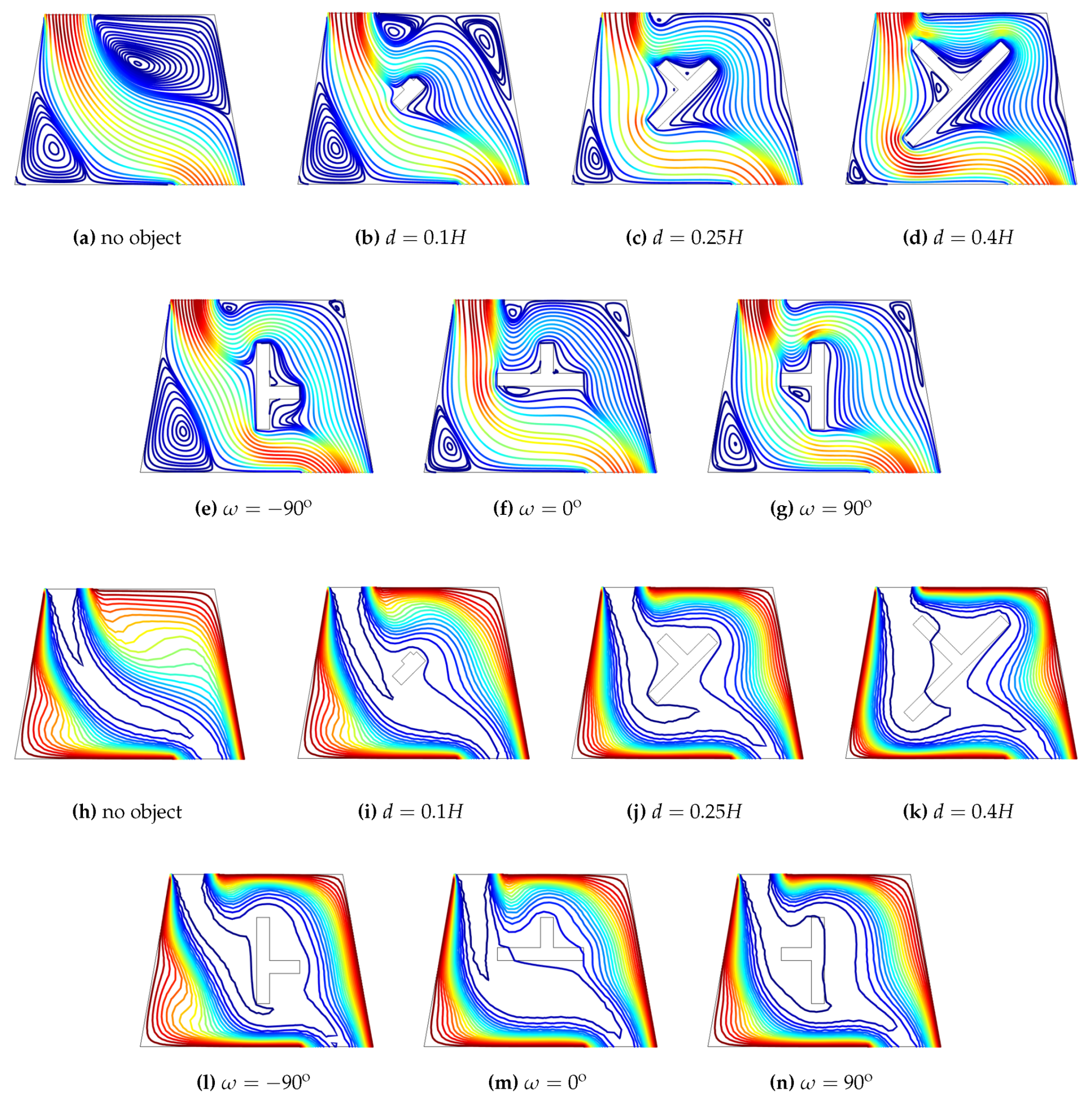
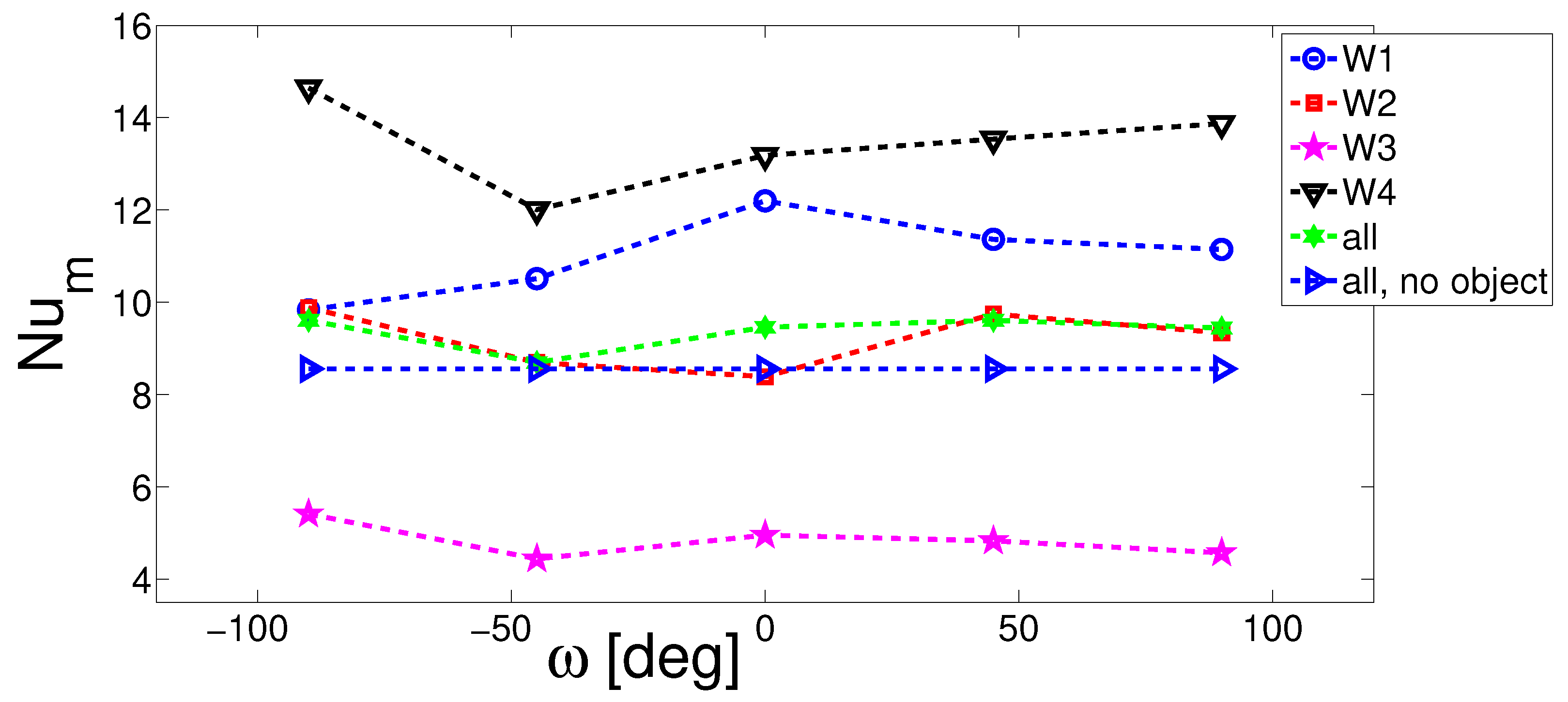
The use of a T-shaped object can generate additional sites for the formation of the vortices, which has an impact on the main flow stream in the cavity. Size and orientations of the T-shaped object had profound effects on the variations of streamlines and isotherms, as shown in Figure 18.The configuration without conductive object is also shown. In the absence of the object, re-circulations were established in the lower and right part of the main flow stream from inlet to outlet. When the object was installed, the vortex in the upper right part broke into two small vortices. Suppression of the corner vortices was seen when the size of the object was increased. The main flow stream from inlet to outlet deflected d more toward the bottom wall with higher size as well. As the orientation of the T-shaped object changed, the size of the vortices changed but more impact was seen on the deflection of the main flow stream. Temperature gradients became intensified with the greater size of the T-shaped object and this effect was more pronounced with size change as compared to altering the orientation of the object. The average Nusselt number enhanced for all walls when the size of the object increased except wall W3, which was above the outlet port (Figure 19). For wall W3, it was reduced until size of d = 0.3 H but increased for d = 0.4 H . This was attributed to the fact that most of the main flow stream was deflected toward the bottom wall for higher sizes but the vortex in the upper right corner was suppressed, which resulted in heat transfer enhancement for size d = 0.4 H .The overall Nu value without object remained below the case with object while the discrepancy between the average Nu value increased with greater size of the object. There were both increment and reduction of the average heat transfer rate for different hot wall segments with different orientations of the object compared to location at ω = 0 (Figure 20).
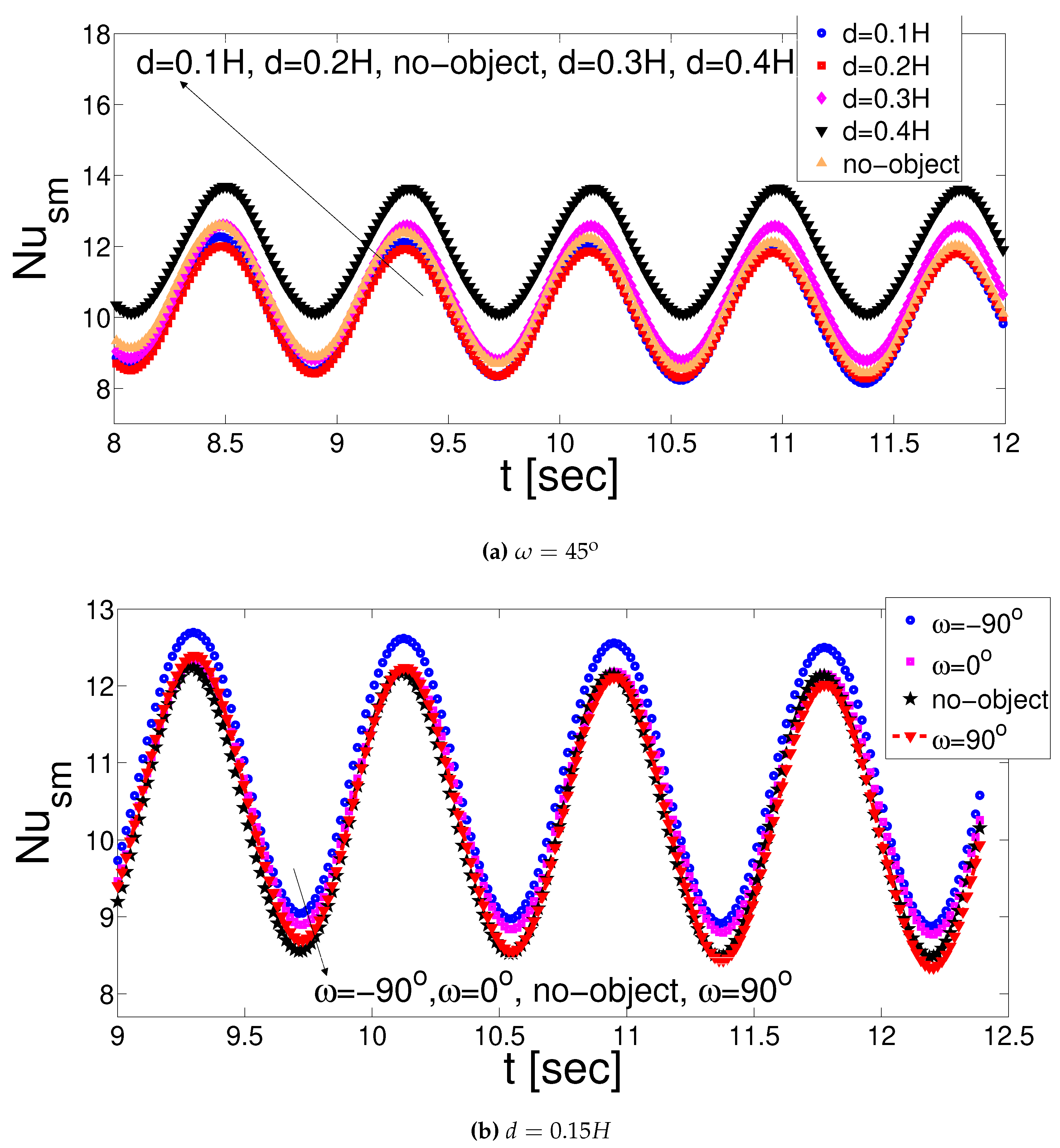
Spatial average Nusselt number increased as the size of T-shaped object increased and the variation was small when different orientations of the object were compared(Figure 21). The overall average Nusselt number increased with greater size of the T-shaped object, similar to the steady flow configuration. However, HTE value was reduced from 41.85 to 20.81 when d was increased from 0.1 H to 0.4 H (Figure 22), which was attributed to the higher Nusselt number enhancement in pulsating flow compared to the steady flow case. The impact of inclination angle of the T-shaped object is shown in Table 5. When pulsating and steady flow configurations were compared, a maximum value of HTE = 31.32 was attained. The impact of ω on the variation of Nu number was slight in both steady and pulsating flow cases.

3.5. Pulsation Amplitude, Frequency and CNT Nanoparticle Effects

Figure 23 and Figure 24 show the impact of amplitude and non-dimensional frequency of the pulsating flow on the variation of Nusselt number and heat transfer enhancements. When the amplitude of pulsation rose, heat transfer enhancement was seen for the average Nusselt number. When the amplitude of the pulsation was varied, there was negligible phase shift for the peak Nu value. For higher amplitudes of the pulsation, impact of magnetic field strength on the average Nu number was less effective. HTE rose for higher amplitudes; however, with the rise of Ha number, its value reduced. At A = 0.9 , HTE reduced from 33 to 22 when Ha was increased from 0 to 30. This was due to the higher heat transfer enhancement in steady flow with higher Ha numbers as compared to pulsating flow case. When the flow pulsation frequency was varied, the highest HTE was attained at St = 0.5 for Ha = 0 and Ha = 10 while HTE reduced with higher values of Strouhal number at Ha = 30. When the flow pulsation was promoted, additional vortices were established near the walls of the cavity and T-shaped object and thermal gradients near the hot walls were disturbed. This resulted in heat transfer enhancement for higher amplitudes. The flow pulsation effects became reduced when the value of Ha was further increased. Inclusion of highly conductive CNT nanoparticles increased the heat transfer rate significantly, as shown in Table 6 for steady and pulsating flow configurations. When there was no magnetic field in the system, the average Nu number increments were 107.63% and 97.66% for steady and pulsating flow cases, respectively, for the nanofluid (highest particle volume fractions) as compared to water while these values were 105.42% and 103.62% when magnetic field effects were considered for Ha = 30. HTE values reduced with higher ϕ in the absence of magnetic field; however, at Ha = 30, the variation of HTE was small when values at different ϕ were compared.

4. Conclusions

Mixed convection of nanofluid (CNT–water) in a ventilated cavity considering magnetic field effects and an inner T-shaped conductive obstacle was numerically examined. It was observed that the average Nu number reduces with higher values of Ri number and wall inclination angle but the effect becomes reverse for higher values of Ha number and nanoparticle volume fraction. Different hot wall segments contributed differently to the overall Nu number with respect to changes in Richardson number, Hartmann number, and side wall inclination angle. When pulsating flow was promoted, higher heat transfer rates were found as compared to steady flow configuration. Suppression of the recirculation regions within the enclosure and in the vicinity of the T-shaped object were seen when with higher values of Ha number. Heat transfer enhancement was highest for lower value of Richardson number in pulsating flow but the trend was opposite for higher values of Hartmann number. Increment of side wall inclination angle from 0 to 30 resulted in rise of HTE from 21 to 48. The inclusion of the conductive T-shaped object and changing it size and orientation had significant impact on the variation of flow and thermal patterns with the cavity. Corner vortices and main flow in the enclosure were influenced by different sizes of the object. Heat transfer enhancement of 41.85% and 20.81% were obtained with flow pulsation when the size was increased from 0.1 H to 0.4 H. When the flow pulsation amplitude rose, heat transfer enhancement was seen but the amount of increment depended on the magnetic field strength. The impact of flow pulsation frequency was not as significant on the heat transfer enhancement as compared to amplitude of pulsation and the highest HTE was attained at Strouhal number of 0.5 for Ha = 0 and Ha = 10. Significant heat transfer enhancements were obtained with the inclusion of highly conductive CNT particles, which were in the range of 97% and 108% for steady and pulsating flow conditions with or without magnetic field effects, respectively.

Author Contributions

F.S. performed the numerical simulations and wrote some sections of the manuscript. The other authors prepared some other sections of the paper and analyzed the results. All authors contributed equally to reviewing and revising the manuscript. All authors have read and agreed to the published version of the manuscript.

Funding

This research received no external funding.

Conflicts of Interest

The authors declare no conflict of interest.

Abbreviations/Nomenclature

AA mplitude of pulsation
dhalf length of the object
ffrequency of pulsation
GrGrashof number
hlocal heat transfer coefficient
kthermal conductivity
K r conductivity ratio
Hchannel height
HaHartmann number
Hcavity height
nunit normal vector
Nu s local Nusselt number
Nu m average Nusselt number
ppressure
Perone period of oscillation
PrPrandtl number
Rresidual
RiRichardson number
ReReynolds number
StStrouhal number
Ttemperature
ttime
u, vx-y velocity components
U, Vnon-dimensional velocities
Wweight function
x, yCartesian coordinates
X, Ynon-dimensional coordinates
Greek Characters
α thermal diffusivity
η magnetic inclination angle
θ non-dimensional temperature
ν kinematic viscosity
ρ density of the fluid
σ electrical conductivity
τ non-dimensional time
ϕ solid volume fraction
Subscripts
ccold
CNTcarbon nanotube
hhot
maverage
ttime
nfnanofluid
psolid particle

References

  1. Saeidi, S.; Khodadadi, J. Forced convection in a square cavity with inlet and outlet ports. Int. J. Heat Mass Transf. 2006, 49, 1896–1906. [Google Scholar] [CrossRef]
  2. Mahmoudi, A.H.; Shahi, M.; Talebi, F. Effect of inlet and outlet location on the mixed convective cooling inside the ventilated cavity subjected to an external nanofluid. Int. Commun. Heat Mass Transf. 2010, 37, 1158–1173. [Google Scholar] [CrossRef]
  3. Angirasa, D. Mixed convection in a vented enclosure with an isothermal vertical surface. Fluid Dyn. Res. 2000, 26, 219–233. [Google Scholar] [CrossRef]
  4. Roslan, R.; Saleh, H.; Hashim, I. Effect of rotating cylinder on heat transfer in a square enclosure filled with nanofluids. Int. J. Heat Mass Transf. 2012, 55, 7247–7256. [Google Scholar] [CrossRef]
  5. Khanafer, K.; Aithal, S.M.; Vafai, K. Mixed convection heat transfer in a differentially heated cavity with two rotating cylinders. Int. J. Therm. Sci. 2019, 135, 117–132. [Google Scholar] [CrossRef]
  6. Selimefendigil, F.; Ismael, M.A.; Chamkha, A.J. Mixed convection in superposed nanofluid and porous layers in square enclosure with inner rotating cylinder. Int. J. Mech. Sci. 2017, 124, 95–108. [Google Scholar] [CrossRef]
  7. Costa, V.; Raimundo, A. Steady mixed convection in a differentially heated square enclosure with an active rotating circular cylinder. Int. J. Heat Mass Transf. 2010, 53, 1208–1219. [Google Scholar] [CrossRef]
  8. Selimefendigil, F.; Oztop, H.F. Forced convection of ferrofluids in a vented cavity with a rotating cylinder. Int. J. Therm. Sci. 2014, 86, 258–275. [Google Scholar] [CrossRef]
  9. Selimefendigil, F.; Oztop, H.F. Numerical study of MHD mixed convection in a nanofluid filled lid driven square enclosure with a rotating cylinder. Int. J. Heat Mass Transf. 2014, 78, 741–754. [Google Scholar] [CrossRef]
  10. Korichi, A.; Oufer, L. Numerical heat transfer in a rectangular channel with mounted obstacles on upper and lower walls. Int. J. Therm. Sci. 2005, 44, 644–655. [Google Scholar] [CrossRef]
  11. Selimefendigil, F.; Oztop, H.F. Numerical study and identification of cooling of heated blocks in pulsating channel flow with a rotating cylinder. Int. J. Therm. Sci. 2014, 79, 132–145. [Google Scholar] [CrossRef]
  12. Mahmoodi, M.; Sebdani, S.M. Natural convection in a square cavity containing a nanofluid and an adiabatic square block at the center. Superlattices Microstruct. 2012, 52, 261–275. [Google Scholar] [CrossRef]
  13. Selimefendigil, F.; Oztop, H.F. Control of Laminar Pulsating Flow and Heat Transfer in Backward-Facing Step by Using a Square Obstacle. J. Heat Transf. 2014, 136, 081701. [Google Scholar] [CrossRef]
  14. Gangawane, K.M.; Oztop, H.F.; Abu-Hamdeh, N. Mixed convection characteristic in a lid-driven cavity containing heated triangular block: Effect of location and size of block. Int. J. Heat Mass Transf. 2018, 124, 860–875. [Google Scholar] [CrossRef]
  15. Gangawane, K.M. Computational analysis of mixed convection heat transfer characteristics in lid-driven cavity containing triangular block with constant heat flux: Effect of Prandtl and Grashof numbers. Int. J. Heat Mass Transf. 2017, 105, 34–57. [Google Scholar] [CrossRef]
  16. Velazquez, A.; Arias, J.; Montanes, J. Pulsating flow and convective heat transfer in a cavity with inlet and outlet sections. Int. J. Heat Mass Transf. 2009, 52, 647–654. [Google Scholar] [CrossRef] [Green Version]
  17. Selimefendigil, F.; Oztop, H.F. Forced convection and thermal predictions of pulsating nanofluid flow over a backward facing step with a corrugated bottom wall. Int. J. Heat Mass Transf. 2017, 110, 231–247. [Google Scholar] [CrossRef]
  18. Akdag, U.; Akcay, S.; Demiral, D. Heat transfer enhancement with laminar pulsating nanofluid flow in a wavy channel. Int. Commun. Heat Mass Transf. 2014, 59, 17–23. [Google Scholar] [CrossRef]
  19. Jin, D.; Lee, Y.; Lee, D. Effects of the pulsating flow agitation on the heat transfer in a triangular grooved channel. Int. J. Heat Mass Transf. 2007, 50, 3062–3071. [Google Scholar] [CrossRef]
  20. Khanafer, K.; Al-Azmi, B.; Al-Shammari, A.; Pop, I. Mixed convection analysis of laminar pulsating flow and heat transfer over a backward-facing step. Int. J. Heat Mass Transf. 2008, 51, 5785–5793. [Google Scholar] [CrossRef]
  21. Selimefendigil, F.; Oztop, H.F. Pulsating nanofluids jet impingement cooling of a heated horizontal surface. Int. J. Heat Mass Transf. 2014, 69, 54–65. [Google Scholar] [CrossRef]
  22. Oztop, H.F.; Al-Salem, K.; Pop, I. MHD mixed convection in a lid-driven cavity with corner heater. Int. J. Heat Mass Transf. 2011, 54, 494–3504. [Google Scholar] [CrossRef]
  23. Ishak, A.; Nazar, R.; Pop, I. MHD convective flow adjacent to a vertical surface with prescribed wall heat flux. Int. Commun. Heat Mass Transf. 2009, 36, 554–557. [Google Scholar] [CrossRef]
  24. Sheikholeslami, M.; Ganji, D.D. Ferrohydrodynamic and magnetohydrodynamic effects on ferrofluid flow and convective heat transfer. Energy 2014, 75, 400–410. [Google Scholar] [CrossRef]
  25. Hajialigol, N.; Fattahi, A.; Ahmadi, M.H.; Qomi, M.E.; Kakoli, E. MHD mixed convection and entropy generation in a 3-D microchannel using Al2O3-water nanofluid. J. Taiwan Inst. Chem. Eng. 2015, 46, 30–42. [Google Scholar] [CrossRef]
  26. Selimefendigil, F.; Oztop, H.F. Fluid-solid interaction of elastic-step type corrugation effects on the mixed convection of nanofluid in a vented cavity with magnetic field. Int. J. Mech. Sci. 2019, 152, 185–197. [Google Scholar] [CrossRef]
  27. Lee, H.G.; Ha, M.Y.; Yoon, H.S. A numerical study on the fluid flow and heat transfer in the confined jet flow in the presence of magnetic field. Int. J. Heat Mass Transf. 2005, 48, 5297–5309. [Google Scholar] [CrossRef]
  28. Selimefendigil, F.; Oztop, H.F. MHD mixed convection of nanofluid in a flexible walled inclined lid-driven L-shaped cavity under the effect of internal heat generation. Phys. A Stat. Mech. Its Appl. 2019, 534, 122144. [Google Scholar] [CrossRef]
  29. Mahmoudi, A.; Mejri, I.; Abbassi, M.A.; Omri, A. Analysis of MHD natural convection in a nanofluid-filled open cavity with non uniform boundary condition in the presence of uniform heat generation/absorption. Powder Technol. 2015, 269, 275–289. [Google Scholar] [CrossRef]
  30. Nguyen-Thoi, T.; Sheikholeslami, M.; Hamid, M.; ul Haq, R.; Shafee, A. CVFEM modeling for nanofluid behavior involving non-equilibrium model and Lorentz effect in appearance of radiation. Phys. A Stat. Mech. Its Appl. 2019, 534, 122154. [Google Scholar] [CrossRef]
  31. Li, Z.; Sheikholeslami, M.; Chamkha, A.J.; Raizah, Z.A.; Saleem, S. Control volume finite element method for nanofluid MHD natural convective flow inside a sinusoidal annulus under the impact of thermal radiation. Comput. Methods Appl. Mech. Eng. 2018, 338, 618–633. [Google Scholar] [CrossRef]
  32. Sheikholeslami, M.; Ganji, D.D. Entropy generation of nanofluid in presence of magnetic field using Lattice Boltzmann Method. Phys. A Stat. Mech. Its Appl. 2015, 417, 273–286. [Google Scholar] [CrossRef]
  33. Sheikholeslami, M.; Rokni, H.B. Numerical modeling of nanofluid natural convection in a semi annulus in existence of Lorentz force. Comput. Methods Appl. Mech. Eng. 2017, 317, 419–430. [Google Scholar] [CrossRef]
  34. Rashid, I.; Sagheer, M.; Hussain, S. Entropy formation analysis of MHD boundary layer flow of nanofluid over a porous shrinking wall. Phys. A Stat. Mech. Its Appl. 2019, in press. [Google Scholar] [CrossRef]
  35. Abbas, N.; Awan, M.B.; Amer, M.; Ammar, S.M.; Sajjad, U.; Ali, H.M.; Zahra, N.; Hussain, M.; Badshah, M.A.; Jafry, A.T. Applications of nanofluids in photovoltaic thermal systems: A review of recent advances. Phys. A Stat. Mech. Its Appl. 2019, in press. [Google Scholar] [CrossRef]
  36. Manca, O.; Mesolella, P.; Nardini, S.; Ricci, D. Numerical study of a confined slot impinging jet with nanofluids. Nanoscale Res. Lett. 2011, 6, 188. [Google Scholar] [CrossRef] [Green Version]
  37. Mahian, O.; Kianifar, A.; Heris, S.Z.; Wen, D.; Sahin, A.Z.; Wongwises, S. Nanofluids effects on the evaporation rate in a solar still equipped with a heat exchanger. Nano Energy 2017, 36, 134–155. [Google Scholar] [CrossRef]
  38. Mahian, O.; Kianifar, A.; Kalogirou, S.A.; Pop, I.; Wongwises, S. A review of the applications of nanofluids in solar energy. Int. J. Heat Mass Transf. 2013, 57, 582–594. [Google Scholar] [CrossRef]
  39. Selimefendigil, F.; Oztop, H.F. Identification of forced convection in pulsating flow at a backward facing step with a stationary cylinder subjected to nanofluid. Int. Commun. Heat Mass Transf. 2013, 45, 111–121. [Google Scholar] [CrossRef]
  40. Chamkha, A.J.; Abu-Nada, E. Mixed convection flow in single- and double-lid driven square cavities filled with water—Al2O3 nanofluid: Effect of viscosity models. Eur. J. Mech. B/Fluids 2012, 36, 82–96. [Google Scholar] [CrossRef]
  41. Al-Waeli, A.H.; Sopian, K.; Chaichan, M.T.; Kazem, H.A.; Hasan, H.A.; Al-Shamania, A.N. An experimental investigation of SiC nanofluid as a base-fluid for a photovoltaic thermal PV/T system. Energy Convers. Manag. 2017, 142, 547–558. [Google Scholar] [CrossRef]
  42. Ellahi, R.; Hassan, M.; Zeeshan, A.; Khan, A.A. The shape effects of nanoparticles suspended in HFE-7100 over wedge with entropy generation and mixed convection. Appl. Nanosci. 2016, 6, 641–651. [Google Scholar] [CrossRef] [Green Version]
  43. Ellahi, R.; Hassan, M.; Zeeshan, A. Particle shape effects on Marangoni convection boundary layer flow of a nanofluid. Int. J. Numer. Methods Heat Fluid Flow 2016, 26, 2160–2174. [Google Scholar] [CrossRef]
  44. Alsabery, A.I.; Gedik, E.; Chamkha, A.J.; Hashim, I. Effects of two-phase nanofluid model and localized heat source/sink on natural convection in a square cavity with a solid circular cylinder. Comput. Methods Appl. Mech. Eng. 2019, 346, 952–981. [Google Scholar] [CrossRef]
  45. Minea, A.A.; Buonomo, B.; Burggraf, J.; Ercole, D.; Karpaiya, K.R.; Pasqua, A.D.; Sekrani, G.; Steffens, J.; Tibaut, J.; Wichmann, N.; et al. NanoRound: A benchmark study on the numerical approach in nanofluids’ simulation. Int. Commun. Heat Mass Transf. 2019, 108, 104292. [Google Scholar] [CrossRef]
  46. Minea, A.A.; Estelle, P. Numerical study on CNT nanofluids behavior in laminar pipe flow. J. Mol. Liq. 2018, 271, 281–289. [Google Scholar] [CrossRef]
  47. Kumaresan, V.; Velraj, R. Experimental investigation of the thermo-physical properties of water-ethylene glycol mixture based CNT nanofluids. Thermochim. Acta 2012, 545, 180–186. [Google Scholar] [CrossRef]
  48. Al-Rashed, A.; Kolsi, L.; Oztop, H.F.; Aydi, A.; Malekshah, E.H.; Abu-Hamdeh, N.; Borjini, M.N. 3D magneto-convective heat transfer in CNT-nanofluid filled cavity under partially active magnetic field. Phys. E Low-Dimens. Syst. Nanostruct. 2018, 99, 294–303. [Google Scholar] [CrossRef]
  49. Ghozatloo, A.; Rashidi, A.M.; Shariaty-Niasar, M. Effects of surface modification on the dispersion and thermal conductivity of CNT-water nanofluids. Int. Commun. Heat Mass Transf. 2014, 54, 1–7. [Google Scholar] [CrossRef]
  50. Xue, Q. Model for thermal conductivity of carbon nanotube-based composites. Phys. B 2005, 368, 302–307. [Google Scholar] [CrossRef]
  51. Al-Rashed, A.; Kolsi, L.; Kalidas, K.; Malekshah, E.H.; Borjini, M.N.; Kanna, P.R. Second law analysis of natural convection in a CNT-water nanofluid filled inclined 3D cavity with incorporated Ahmed body. Int. J. Mech. Sci. 2017, 130, 399–415. [Google Scholar] [CrossRef]
  52. Selimefendigil, F.; Oztop, H.F. Corrugated conductive partition effects on MHD free convection of CNT-water nanofluid in a cavity. Int. J. Heat Mass Transf. 2019, 129, 265–277. [Google Scholar] [CrossRef]
  53. Selimefendigil, F.; Oztop, H.F. Numerical analysis and ANFIS modeling for mixed convection of CNT-water nanofluid filled branching channel with an annulus and a rotating inner surface at the junction. Int. J. Heat Mass Transf. 2018, 127, 583–599. [Google Scholar] [CrossRef]
  54. Naphon, P.; Wiriyasart, S. Pulsating TiO2/water nanofluids flow and heat transfer in the spirally coiled tubes with different magnetic field directions. Int. J. Heat Mass Transf. 2017, 115, 537–543. [Google Scholar] [CrossRef]
  55. Selimefendigil, F. Numerical investigation and recurrence plot analysis of pulsating magnetohydrodynamic mixed convection over a backward facing step. Nonlinear Anal. Model. Control 2015, 20, 428–446. [Google Scholar] [CrossRef]
  56. Selimefendigil, F.; Oztop, H.F. MHD Pulsating forced convection of nanofluid over parallel plates with blocks in a channel. Int. J. Mech. Sci. 2019, 157–158, 726–740. [Google Scholar] [CrossRef]
  57. Mehrez, Z.; Cafsi, A.E.; Belghith, A.; Quéré, P.L. MHD effects on heat transfer and entropy generation of nanofluid flow in an open cavity. J. Magn. Magn. Mater. 2015, 374, 214–224. [Google Scholar] [CrossRef]
  58. Jiang, H.; Zhang, Q.; Shi, L. Effective thermal conductivity of carbon nanotube-based nanofluid. J. Taiwan Inst. Chem. Eng. 2015, 2015, 76–81. [Google Scholar] [CrossRef]
  59. Brinkman, H. The viscosity of concentrated suspensions and solutions. J. Chem. Phys. 1952, 20, 571–581. [Google Scholar] [CrossRef]
  60. Benos, L.; Karvelas, E.; Sarris, I. A theoretical model for the magnetohydrodynamic natural convection of a CNT-water nanofluid incorporating a renovated Hamilton-Crosser model. Int. J. Heat Mass Transf. 2019, 135, 548–560. [Google Scholar] [CrossRef]
  61. Selimefendigil, F.; Oztop, H.F. Effects of an inner stationary cylinder having an elastic rod-like extension on the mixed convection of CNT-water nanofluid in a three dimensional vented cavity. Int. J. Heat Mass Transf. 2019, 137, 650–668. [Google Scholar] [CrossRef]
  62. Selimefendigil, F.; Oztop, H.F. Control of natural convection in a CNT-water nanofluid filled 3D cavity by using an inner T-shaped obstacle and thermoelectric cooler. Int. J. Mech. Sci. 2019. [Google Scholar] [CrossRef]
  63. Halelfadl, S.; Estelle, P.; Aladag, B.; Doner, N.; Mare, T. Viscosity of carbon nanotubes water based nanofluids: Influence of concentration and temperature. Int. J. Therm. Sci. 2013, 71, 111–117. [Google Scholar] [CrossRef] [Green Version]
  64. Sourtiji, E.; Gorji-Bandpy, M.; Ganji, D.; Hosseinizadeh, S. Numerical analysis of mixed convection heat transfer of Al2O3-water nanofluid in a ventilated cavity considering different positions of the outlet port. Powder Technol. 2014, 262, 71–81. [Google Scholar] [CrossRef]
  65. Ghasemi, B.; Aminossadati, S.M.; Raisi, A. Magnetic field effect on natural convection in a nanofluid-filled square enclosure. Int. J. Therm. Sci. 2011, 50, 1748–1756. [Google Scholar] [CrossRef]
Figure 1. Schematic representation of computational model (not to scale) (a) and grid distribution (b).
Energies 13 00848 g001aEnergies 13 00848 g001b
Figure 2. Comparisons of average Nu variation with respect to changes in Reynolds number (a) and differences between the comparisons (b) for mixed convection in cavity at Richardson number of 10.
Energies 13 00848 g002
Figure 3. Effects of Richardson number on the distribution of streamlines (ac) and isotherms (df) (Ha = 20, Ω = 45 , ω = 45 , d = 0.15 H ).
Energies 13 00848 g003
Figure 4. Average Nusselt number variations with respect to changes in Richardson number for individual walls (a) and for all walls (b) (Ha = 20, Ω = 45 , ω = 45 , d = 0.15 H ).
Energies 13 00848 g004
Figure 5. Contribution of different hot wall segments to the overall heat transfer rate for various values of Richardson number (Ha = 20, Ω = 45 , ω = 45 , d = 0.15 H ).
Energies 13 00848 g005
Figure 6. Variation of streamlines (ae) and isotherms (fj) in the vented cavity for various time instances within a period of the pulsating flow (Ha = 10, Ω = 10 , ω = 45 , d = 0.15 H , A = 1 , St = 0.5).
Energies 13 00848 g006
Figure 7. Spatial averaged Nusselt number (considering all hot walls) variations for three different values of Richardson number (Ha = 10, Ω = 10 , ω = 45 , d = 0.15 H , A = 1 , St = 0.5).
Energies 13 00848 g007
Figure 8. Influence of magnetic field strength on the distributions of streamlines (ac) and isotherms (df) (Ri = 1, Ω = 45 , ω = 45 , d = 0.15 H ).
Energies 13 00848 g008
Figure 9. Average Nusselt number of the hot wall segments (individual (a) and total (b)) for different Hartmann numbers (Ri = 1, Ω = 45 , ω = 45 , d = 0.15 H ).
Energies 13 00848 g009
Figure 10. Contribution of different hot wall segments to the overall heat transfer rate considering different values of Hartmann numbers (Ri = 1, Ω = 45 , ω = 45 , d = 0.15 H ).
Energies 13 00848 g010
Figure 11. Variation of streamlines (ah) and isotherms (ip) in the vented cavity for various time instances within a period of the pulsating flow and for two values of Hartmann number (Ri = 1, Ω = 10 , ω = 45 , d = 0.15 H , A = 1 , St = 0.5).
Energies 13 00848 g011
Figure 12. Impacts of Hartmann number on the variation of spatial averaged Nusselt number considering all hot wall in pulsating flow (Ri = 1, Ω = 10 , ω = 45 , d = 0.15 H , A = 1 , St = 0.5).
Energies 13 00848 g012
Figure 13. Impacts of side wall inclination angle of the vented cavity on the variation of streamlines (ac) and isotherms (df) (Ri = 1, Ha = 10, ω = 45 , d = 0.15 H ).
Energies 13 00848 g013
Figure 14. Effects of cavity side wall inclination angle on the variation of average heat transfer (individual walls (a); and all wall (b)) (Ri = 1, Ha = 10, ω = 45 , d = 0.15 H ).
Energies 13 00848 g014
Figure 15. Impact of cavity side wall inclination angle on the contribution of different hot wall segments to the overall heat transfer rate (Ri = 1, Ha = 10, ω = 45 , d = 0.15 H ).
Energies 13 00848 g015
Figure 16. Variation of streamlines (af) and isotherms (gl) in the vented cavity for various time instances within a period for two values of side wall inclination angle of the vented cavity (Ri = 1, Ha = 10, ω = 45 , d = 0.15 H , A = 1 , St = 0.5).
Energies 13 00848 g016aEnergies 13 00848 g016b
Figure 17. Variation of spatial averaged Nusselt number and heat transfer enhancement in pulsating flow for various values of side wall inclination angles (Ri = 1, Ha = 10, ω = 45 , d = 0.15 H , A = 1 , St = 0.5).
Energies 13 00848 g017
Figure 18. Effects of size and orientation of the T-shaped obstacle on the variation of streamlines (bg) and isotherms (in) in the vented cavity (Ri = 1, Ha = 10, Ω = 10 ). Streamline (a) and isotherm (h) variation in the cavity without object are also shown.
Energies 13 00848 g018
Figure 19. Impacts of size of the T-shaped object on the distribution of the average Nusselt number for individual walls (a) and considering all walls (b) (Ri = 1, Ha = 10, Ω = 10 , ω = 45 ).
Energies 13 00848 g019
Figure 20. Effects of T-shaped object orientation on the variation of the average Nusselt number for individual wall and considering all walls (Ri = 1, Ha = 10, Ω = 10 , d = 0.15 H ).
Energies 13 00848 g020
Figure 21. Variation of spatial averaged Nusselt number in pulsating flow for various values of size and inclination of the T-shaped object (Ri = 1, Ha = 10, Ω = 10 , A = 1 , St = 0.5).
Energies 13 00848 g021
Figure 22. Effects of size of the T-shaped object on the average heat transfer and heat transfer enhancement with pulsating flow (Ri = 1, Ha = 10, Ω = 10 , ω = 10 , A = 1 , St = 0.5).
Energies 13 00848 g022
Figure 23. Effects of pulsating flow amplitude (a) and frequency (b) on the variation of spatial averaged Nusselt number considering all hot walls of the vented cavity for various Hartmann numbers (Ri = 1, Ω = 10 , ω = 45 , d = 0.15 H ).
Energies 13 00848 g023
Figure 24. Average Nusselt number and heat transfer enhancement with pulsating flow amplitude (a,b) and frequency (c,d) (Ri = 1, Ω = 10 , ω = 45 , d = 0.15 H ).
Energies 13 00848 g024
Table 1. Grid independence test for various grid sizes: The average Nusselt number comparisons considering all hot walls of the vented cavity for different values of Ri and Ha numbers for different grids while the other values are fixed to Ω = 10 , ω = 45 , and d = 0.15 H .
RiHaGrid Type (Number of Elements)
G1 (1433)G2 (3038)G3 (6127)G4 (12814)G5 (49897)
0.05057.90340.88626.23723.71323.522
0.051057.64940.66725.86623.36923.196
0.053057.36840.86825.67123.48923.371
5004.0784.0543.9744.0204.041
50103.9663.9343.8273.8763.898
50304.1764.1384.0284.1014.124
Table 2. Average Nusselt number comparisons calculated with the present solver and obtained by Ghasemi et al. [65] for convection in cavity considering magnetic field effects for various Rayleigh numbers while the Hartmann number is fixed to 30.
RaCurrent StudyRef. [65]
10 4 1.1791.183
10 6 7.8697.907
10 7 16.70216.929
Table 3. Heat transfer enhancement with pulsating flow for different values of Richardson numbers (Ha = 10, Ω = 10 , ω = 45 , d = 0.15 H , A = 1 , St = 0.5).
Ri Steady (Average Nu) Pulsating (Highest Value of Space Average Nu) HTE
0.119.9329.2046.51
19.6110.9513.94
105.516.9726.49
Table 4. Heat transfer enhancement with pulsating flow for various values of Hartmann number (Ri = 1, Ω = 10 , ω = 45 , d = 0.15 H , A = 1 , St = 0.5).
Ha Steady (Average Nu) Pulsating (Highest Value of Space Average Nu HTE
09.5612.4830.54
109.6112.2327.26
3010.6612.7019.13
Table 5. Heat transfer enhancement in pulsating flow with various values of orientation of the T-shaped object in the vented cavity (Ri = 1, Ha = 10, Ω = 10 , d = 0.15 H , A = 1 , St = 0.5).
ω (deg) Steady (Average Nu) Pulsating (Highest Value of Space Average Nu) HTE
−909.6112.6231.32
09.4612.2329.28
909.4412.1829.02
Table 6. Heat transfer enhancement with CNT nanoparticles (Ha = 10, Ω = 10 , ω = 45 , d = 0.15 H , A = 1 , St = 0.5).
Ha = 0
ϕ Steady (Average Nu)Pulsating (Highest Value of Space Average Nu)HTE
08.556.4233.17
0.0110.257.9129.58
0.0212.309.5728.52
0.0314.5811.3728.23
0.0416.9013.3326.78
Ha = 30
ϕ Steady (Average Nu)Pulsating (Highest Value of Space Average Nu)HTE
08.557.1918.54
0.0110.608.8419.89
0.0212.7010.6619.14
0.0314.9612.6318.44
0.0417.4114.7717.87