Article

Damage Evolution Mechanisms of Rock Induced by Blasting with the Aid of Empty-Hole Effect

1
State Key Laboratory of Coal Resources and Safe Mining, China University of Mining and Technology, Xuzhou 221116, China
2
School of Mines, China University of Mining and Technology, Xuzhou 221116, China
*
Author to whom correspondence should be addressed.
Energies 2020, 13(3), 756; https://doi.org/10.3390/en13030756
Submission received: 13 January 2020 / Revised: 4 February 2020 / Accepted: 6 February 2020 / Published: 9 February 2020
(This article belongs to the Section L: Energy Sources)

Abstract

:
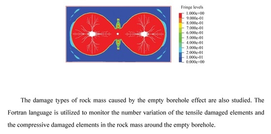
Blasting has been widely used in coal mining as a method of reducing the integrity of rock mass. Its low controllability often leads to the unsatisfactory fragmentation effect of rock mass. The empty borehole effect has great significance in avoiding the excessive breakage of rock mass and guiding the directional propagation of blasting-induced fractures. Nevertheless, the rock mass damage type evolution induced by the empty borehole has been rarely studied. A tension–compression constitutive model of rock mass damage is established in this paper. The model is incorporated into the numerical modeling code LS-DYNA as a user-defined material model. Then, LS-DYNA is used to investigate the evolution mechanism of rock mass damage under the empty borehole effect. The damage types of rock mass caused by the empty borehole effect are also studied. The Fortran language is utilized to monitor the number variation of the tensile damaged elements and the compressive damaged elements in the rock mass around the empty borehole. The results indicate that existence of the empty borehole significantly enhances the tensile stress and the stress concentration factor in the rock mass nearby the empty borehole. Meanwhile, the rock mass nearby the empty borehole mainly damages in tension. Both the number of the tensile damaged elements and the tensile stresses in the elements increases as the empty borehole diameter increases. The number of the compressive damaged elements decreases with increasing empty borehole diameter.

Graphical Abstract

1. Introduction

Drilling and blasting are some of the most commonly used methods for rock breaking. Due to their advantages of good applicability to various geotechnical conditions, low cost, and easy operation, they have been widely applied to mine chamber excavation and water conservancy and hydropower engineering [1,2,3]. The conventional blasting technique has certain limitations and normally leads to undesirable effects. Over-breaking or under-breaking may occur in the tunnel excavation. Empty holes can promote the development of cracks in the explosion process, improve the blasting efficiency, and reduce the number of explosions, thus reducing the disturbance to the coal pillar. Therefore, some researchers proposed the concept of arranging empty boreholes (i.e., boreholes used to guide the fracture propagation from adjacent blasting boreholes) between the blasting boreholes in order to control the rock mass damage and promote the directional development of cracks in the roof rock mass. Yue et al. [4] found that the empty borehole is able to change the stress distribution in the rock mass and induce the initiation and directional propagation of the blasting-induced fractures.
The existence of the empty borehole in the rock can change the stress distribution and the damage zone in the rock mass [5]. The empty borehole concept has been successfully applied to rock fracturing, tunnel excavation, and coal seam gas extraction [6,7]. The dynamic evolution of the blasting-induced stress and the directional propagation of the blasting-induced fractures have been widely studied by many researchers based on theoretical analysis and laboratory experiments. Cho et al. [8] investigated the influence of the empty borehole on fracture propagation, using polymethyl methacrylate (PMMA) and revealed the law of fracture propagation from the aspect of stress concentration. Based on the evolution characteristics of the fractures between blasting boreholes, He and Yang [9] studied the law of fracture propagation between adjacent boreholes, using a high-speed camera and digital image processing. Ma and An [10] simulated the stress evolution and fracture propagation around an empty borehole in the blasting process by numerical modeling and provided a theoretical basis for the formation of blasting-induced fractures. Chen et al. [11] used LS-DYNA (a numerical modeling code) to simulate the effective stress distribution in the rock under the superimposition effect of stress waves and reflected waves. Many researchers analyzed the blasting models to study the damage evolution in the blasting process. The existing models include the Taylor–Chen–Kuszmaul model [12], the Kuszmaul model [13], the Barton–Bandis model [14], and the rock damage model [15]. However, only the effect of tensile stress on rock mass damage was considered in the above studies. This poses limitations to the existing blasting damage model. To fill this research gap, Wu et al. [16] proposed a tension–compression blasting damage model based on compressive damage and tensile damage and determined the damage law of the rock under the effect of both the tensile stress and the compressive stress, considering the cumulative damage variable as the linear combination of the tensile damage variable and the compressive damage variable. Hu et al. [17] introduced a method of calculating compressive damage based on the RDA model and established a tension–compression damage model [18,19,20]. Many other researchers established different tension–compression damage models, using various strength criteria. The rock mass tension–compression damage model is able to reflect the change law of rock mass unit damage type under blasting loading more accurately [21,22,23,24,25]. Meanwhile, many researchers have analyzed the effect of empty holes on rock damage [26,27].
The above studies disclosed the influence of the empty borehole on fracture evolution and stress transmission in the rock mass under dynamic loading. However, the rock mass is under both the effect of static loading and the effect of dynamic loading in the blasting process, and hence exhibits different mechanical responses [28,29]. The mechanism of rock mass damage under combined static and dynamic loading needs to be further investigated. Moreover, we study the evolution law of the tensile damage and the compressive damage units in the rock mass induced by the empty borehole.
To study the effect of the empty borehole on the damage evolution in the rock mass under blasting loading, an empty borehole is arranged between the blasting boreholes in order to guide blasting-induced fracture propagation and change the stress distribution in the rock mass. The blasting technology of empty hole reduces the damage of rock mass and improves the blasting efficiency. When the impact wave or the stress wave acts on the rock mass, the rock element sustains tensile failure or compressive failure. Therefore, a rock mass tension–compression damage model is established and incorporated into LS-DYNA as a user-defined model. The reliability of the model is validated by comparing the numerical modeling results with the field testing results. The in situ stress is set as a constant to consider the influence of static loading (i.e., the in situ stress) on rock mass damage. A numerical model is established in LS-DYNA to analyze the propagation law of the stress wave in the rock mass and the evolution process of rock mass damage. The effect of the empty borehole diameter on the rock mass damage zone is studied. The damage type evolution of the rock mass around the empty boreholes with different diameters is analyzed. The Fortran language is used to monitor the damage type of the rock mass around the empty borehole, and the numbers of the tensile damage elements and the compressive damage elements are recorded.

2. Solution and Algorithm in Blasting Model

After the explosive blasts in the borehole, the shock wave interacts with the rock mass around the borehole and produces the impact wave in the rock mass. When the impact wave acts on the rock mass, rock mass failure occurs due to large deformation. When the numerical method is used to solve large deformation problems, the rock element is likely to sustain large deformation. This could lead to an abnormal termination of the calculation. LS-DYNA is a non-linear numerical modeling code that is capable of modeling complex non-linear dynamic mechanical problems and has tremendous advantages in solving geometrical non-linear problems, material non-linear problems, and contact non-linear problems [30]. Currently, LS-DYNA mainly consists of three algorithms, including the Lagrange algorithm (LA), the Euler algorithm (EA), and the arbitrary Lagrange–Euler (ALE) algorithm. The EA algorithm and the ALE algorithm are commonly used to solve non-linear dynamic problems related to large deformation. Considering that the rock mass is subjected to in situ stress (static loading), the in situ stress should be applied to the numerical model before the dynamic analysis is performed. In LS-DYNA, static–dynamic coupling problems can be effectively solved by the implicit–explicit calculation method.

2.1. Lagrange, Euler and ALE Algorithms

Hallquist [30] detailed the applicability of the Lagrange, Euler, and ALE algorithms. When the Lagrange algorithm is adopted, large deformation occurs in the rock element after blasting, causing the abnormal termination of the numerical calculation. The fluid–solid coupling method can be used to solve this problem. The ALE algorithm and the Lagrange algorithm are used to deal with the explosive material and the rock material respectively. The fluid–solid coupling method was also used by Wang [31] to solve the abnormal termination problem resulting from the large deformation of the rock element in the blasting process.

2.2. Implicit–Explicit Analysis Method

The implicit–explicit analysis method in LS-DYNA can be used to apply the in situ stress to the numerical model before the dynamic analysis is conducted. In the numerical calculation, the explicit algorithm in LS-DYNA has better ability to deal with the dynamic problem [32]. The implicit algorithm in ANSYS/LS-DYNA has the advantage of solving static problems. The static–dynamic coupling (in situ stress blasting coupling) problem can be effectively solved by the implicit–explicit analysis method in LS-DYNA that combines the advantages of both the implicit algorithm and the explicit algorithm. The calculation procedures are given as follows.
(1)
Perform the implicit analysis in ANSYS and apply the in situ stress (static loading) to the numerical model. The ‘entity 185′ type element is used in the implicit analysis. Then, we apply the boundary conditions to the numerical model. Finally, we conduct the numerical calculation of the numerical model.
(2)
Convert the implicit analysis in ANSYS into the explicit analysis in LS-DYNA. To generate the in situ stress in the explicit analysis in LS-DYNA, the ‘entity 185′ type elements in ANSYS need to be converted into the ‘entity 164′ element (with 8 nodes) in LS-DYNA. A dynamic relaxation file is generated in the conversion process. The displacements in the dynamic relaxation file are used to generate the in situ stress in the explicit analysis in LS-DYNA.

2.3. Simulation Process

Perform the explicit analysis. After the implicit analysis is converted into the explicit analysis, the in situ stress is created according to the displacements in the relaxation file and the selected constitutive model. The Kinematic Hardening model used in this paper considers both the tensile damage and the compressive damage. To apply the detonation loading to the borehole, the explosive material is used in the numerical model.

3. Constitutive Model Establishment

3.1. Explosive State Equation

Explosion is a fast chemical reaction process. In LS-DYNA, many researchers proposed different Equation-of-state (EOS) models to describe the explosion products created by the chemical reaction process, such as the Jones–Wilkens–Lee (JWL) model and the Jones–Wilkens–Lee–Baker (JWLB) model. The JWL model is a high-energy combustion model, while the JWLB model is a standard low-pressure explosion model [33]. If the JWLB model is used, the reaction rate of the explosive in the low-pressure reaction process and the parameters in the JWL model are required. Due to insufficient experimental data of explosives, it is difficult to apply the JWLB model to engineering simulation. However, the JWL EOS successfully predicted the extent of the blasting-induced pressure. The parameters in the JWL EOS can be obtained by laboratory experiments. Sanchidrian et al. [34] derived the parameters in the JWL EOS by laboratory experiments. The JWL EOS is used to study the blasting process in this paper. The JWL EOS is given in Equation (1) [33,34]:
P b = A ( 1 ω R 1 V ) e ( V R 1 ) + B ( 1 ω R 1 V ) e V R 2 + ω E i V
where Pb is the pressure applied to the borehole wall by a unit explosion product, V is the relative volume of the explosion product, Ei is the initial internal energy density of the explosion product, and A, B, R1, R2 and ω are the material constants determined by blasting experiments. These JWL constants can be obtained by experiments [35]. In the paper, the #2 emulsion explosive is selected. However, due to the limitation of the measurement instruments, the JWL EOS parameters of the explosive are adapted with permission from Chen et al. [11] (Table 1 and Table 2).

3.2. Tension–Compression Damage Model

When the impact wave and the stress wave transmit in the rock mass and the stress exceeds the compressive strength or the tensile strength of the rock, compressive damage or tensile damage occurs in the rock mass. A rock mass tension–compression damage model is established based on the failure mode of the rock mass under blasting loading. Moreover, the mechanical properties of the rock mass is influenced by the strain rate when the rock mass sustains the dynamic loading induced by blasting. A tension–compression Kinematic Hardening damage model is established based on the strain rate effect and the failure mode of the rock mass under dynamic blasting loading.

3.2.1. Kinematic Hardening Model Based on Plastic Strain Rate

A model that reflects the sensitivity of the plastic strain rate is adopted to consider the strain rate effect of the rock under dynamic blasting loading [36]. Equations (2) to (4) give the relation between the yield stress and the strain rate:
σ y = [ 1 + ( ε ˙ c ) 1 p ] ( σ y 0 + β E p ε e f f p )
E P = E 0 E t a n E 0 E t a n
ε e f f p = 0 t d ε e f f p
where c and p are the constants in the Kinematic Hardening model, ε ˙ is the strain rate, σy is the yield stress, β is the hardening parameter (0 ≤ β ≤ 1), Ep is the plastic hardening modulus, E0 is the Young’s modulus, Etan is the tangent modulus, and ε e f f p is effective plastic strain. The values of c and p are determined by the stress–strain curves under different strain rates. Based on the results of Yang et al. [37], the values of c and p are set to 4.0 and 2.5, respectively [38]. For the isotropic hardening material, β is assumed to be 1 [37].

3.2.2. Rock Mass Damage Criterion

To describe rock mass damage under compressive and tensile loading, the strength criterion is used to judge the damage degree of the rock mass. A generalized equation (Equation (5)) is used to describe the relation between the strength and the stress:
F ( σ ) S = 0
where S is the rock strength and F(σ) is the rock mass stress state function. If F(σ) ≥ S, rock damage occurs [39]. Based on Equation (5), tensile damage and compressive damage in the rock mass are determined by the maximum tensile stress and the semi-empirical criterion in this paper [40]. When tensile damage occurs, F(σ) equals the maximum tensile stress (σ1), and S equals dynamic tensile strength (σts). The compressive damage of the rock mass is judged by Equation (6) based on the semi-empirical equation:
σ 1 σ 3 M c σ cs
where σcs is dynamic compressive strength (which equals S) and Mc is a material constant related to rock strength.
Equation (7) is derived if Equations (5) and (6) are combined:
F ( σ ) = ( σ 1 σ 3 ) / M c
where Mc ranges from 0.4 to 0.6. For the rock mass with medium strength, Mc ranges from 0.4 to 0.5. For the rock mass with high strength, Mc ranges from 0.5 to 0.6. The Mc value in this paper is set to 0.5 [40].
According to the above analysis, F(σ) can be expressed by Equation (8):
F ( σ ) = { σ 1 , ε v 0 σ 1 σ 3 M c , ε v > 0
where εv is the volumetric strain. The rock mass is in tension if εv ≤ 0. Otherwise, the rock mass is in compression.
Rock strength under dynamic loading is related to the strain rate [38]. The relation between dynamic tensile strength and the strain rate and the relation between dynamic compressive strength and the strain rate can be expressed by Equations (9) and (10) respectively:
σ ts = A t ε ˙ 0.3
σ c s = B t ε ˙ 0.3
where At and Bt are material constants related to the static tensile strength and static compressive strength, respectively. The values of material constants At and Bt are 0.81 and 0.52, respectively.

3.2.3. Evolution of Damaged Rock Element

Pisarenko and Lebedev [41] assumed that many microcracks and defects are randomly distributed in the material. It is reasonable to describe the statistical characteristics of material strength by statistical distribution functions. To describe the random distribution of the microscopic rock mass strength, Krajcinovic and Silva [42] proposed the continuum damage theory based on the statistical damage model, using the statistical strength theory.
To determine the relation between rock mass damage and rock mass strength in the statistical damage model, the deformation and damage in the rock mass is assumed to be a continuous process. The rock element has the following properties.
(1)
The macroscopic rock properties are assumed to be isotropic.
(2)
The microscopic rock element obtains Hooke’s law before damage (i.e., linear elastic deformation).
The strength of the microscopic elements obtains the Weibull distribution, and the probability density function is defined by Equation (11) [42,43].
Q ( F ) = { n F 0 ( F F 0 ) n 1 e [ ( F F 0 ) n ] , F > 0 0 , F 0
If F is the distribution variable (e.g., the stress and the elastic modulus), F0 is the rock mass strength, and n is the distribution concentration ratio of rock mass strength.
When the magnitude of the impact wave or the stress wave exceeds the rock mass strength, the microscopic element in the rock mass fails. Assuming that the total number of the microscopic elements in the rock mass is M and the number of the damaged elements is Mf, the statistic damage variable can be defined as [43]:
D s = M f M
where Ds is the damage variable. The number of the damaged microscopic elements in the rock is assumed to be M × Q(F) dF if an arbitrary interval [F, F + dF] is given. When the dynamic loading or the static loading increases to F, the number of the damaged microscopic rock elements (Mf) is derived by integrating M × Q(F) dF in the [0, F] interval (Equation (13)) [43].
M f ( F ) = 0 F M × Q ( x ) d x = M { 1 e [ ( F F 0 ) n ] }
The damage variable (Ds) is derived if Equation (13) is incorporated into Equation (12):
D s = 1 e [ ( F F 0 ) n ]
where F is the distribution variable (e.g., the stress and the elastic modulus), and F0 is the rock mass strength. Assuming F = F(σ), the tensile damage degree and the compressive damage degree can be derived by Equations (15) and (16) respectively [39]:
D t s = 1 e [ ( σ 1 σ t s ) n t s ] ε v 0
D c s = 1 e [ ( σ 1 σ 3 M c σ c s ) n c s ] ε v > 0
where Dts is the damage parameters of the tensile stress, Dcs is the damage parameters of the compressive stress. nts and ncs are set to 2.5 and 4.5, respectively [43].
To completely describe the evolution process of rock mass damage and incorporate tensile and compressive damage into LS-DYNA, the rock mass damage type is judged by the maximum value function. The Fortran language is used to record the number of the rock elements sustaining the corresponding damage type. The damage variable is expressed by Equation (17).
D s = m a x [ D t s , D c s ]
Equation (17) represents the latest damage variables by the maximum value determined and assigned the damage variables to the Ds.
The number of the rock elements sustaining tensile damage is calculated by Equation (18).
m t s n = 0 n 1 m t s i ( 1 i n 1 )
where m t s n is the total number of element damage with tensile stress at n step, and m t s i is the number of element damage with tensile stress at the i (1 ≤ in − 1) step.
The number of the rock elements sustaining compressive damage is calculated by Equation (19).
n c s n = 0 n 1 n c s i     ( 1 i n 1 )
where n c s n is the total number of element damage with compressive stress at n step, and n c s i is the number of element damage with compressive stress at the i (1 ≤ in − 1) step.

4. Establishment and Validation of Numerical Model

4.1. Model Validation and Calculation Procedure

4.1.1. Experimental Study

To validate the established model, the numerical modeling results and the experimental study results of the damage induced by the blasting are compared. In the study, vertical cylindrical decoupling charge is used in the blasting excavation of the rock. The blasting borehole diameter is 89 mm, and the roll length ranges from 0.5 to 4.0 m. According to the field practice, a simplified 1/4 cylindrical rock blasting model is simulated. Rock damage is simulated based on the above damage model. Normal constraint is applied to the top, bottom, left, and right boundaries. To eliminate the influence of the reflected wave, the non-reflecting boundary condition is applied to the outer surface [2].

4.1.2. Model Validation

The blasting damage is simulated based on the tension–compression damage model, using the blasting parameters and rock characteristics in Meng et al. [44]. The damage threshold (Dcr) used in Grady and Kipp [45] was 0.20. Figure 1 gives the outlines from the experimental study results and the numerical modeling results. The testing results show that the damage depth and the damage radius are 22.7 cm and 68.0 cm, respectively. The numerical modeling results show that the damage depth and the damage radius are 22.9 cm and 68.1 m, respectively. The numerical modeling results are almost consistent with the field testing results. Therefore, the tension–compression damage model can be used to study the influence of blasting on rock damage [38]. Meanwhile, Xia [38] conducted similar research and proved the feasibility.

4.2. Model Development and Calculation Flowchart

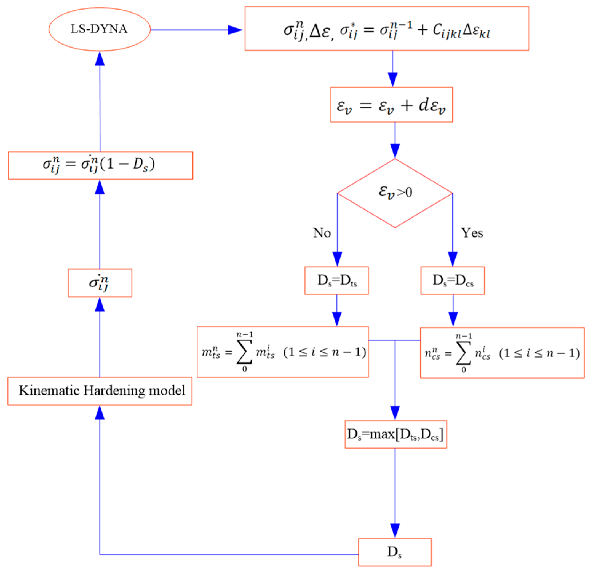
Besides some existing material models, the secondary development interface is available in LS-DYNA. The secondary development of the constitutive model can be realized by incorporating the Fortran language into the user-defined interface. The procedure is given in Figure 2. The calculation procedure for the nth step is given as follows.
(1)
Determine the trial value of stress tensor σ i j * . σ i j * = σ i j n 1 / ( 1 D ) + C i j k l Δ ε k l . ε v = ε v + d ε v ), where Cijkl is the elastic tangent modulus matrix.
(2)
Judge the tensile state or the compressive state of the rock element. If εv > 0, the element is in compression; otherwise, the element is in tension.
(3)
Determine the latest damage variables (Dts and Dcs).
(4)
If the rock element is in tension, the number of the damaged elements increases by 1 (mts = mts + 1); otherwise, ncs = ncs + 1.
(5)
Calculate the trial value of the deviatoric stress tensor based on different stress states ( S i j * = S i j n 1 + 2 G Δ ε i j ), where S i j * is the trial deviatoric stress tensor at n step.
(6)
Calculate the equivalent strain rate ( ε ˙ ).
(7)
Judge the plastic yield condition. If F ≤ 0, the material is in the elastic deformation state, the trial value of the stress is true; otherwise, step into Step (9) to determine the stress tensor σ i j n ¯ .
(8)
If F > 0, the material is in the plastic deformation state; otherwise, determine the plastic multiplier, and then calculate the updated equivalent plastic strain ( ε e f f p ) n = ( ε e f f p ) n 1 + d ε p e f f ; the radial regression of the deviatoric stress to the yield element surface is S i j n = S i j * + ( 3 G α / σ e q ) S i j * , where α is the plastic multiplier.
(9)
Calculate the stress tensor σ i j n ¯ = S i j n p δ i j .
(10)
Update the stress damage σ i j n = σ i j n ¯ ( 1 D s ) .
(11)
Update the history output and return to Step (1) for the new calculation cycle.

4.3. Numerical Model Establishment

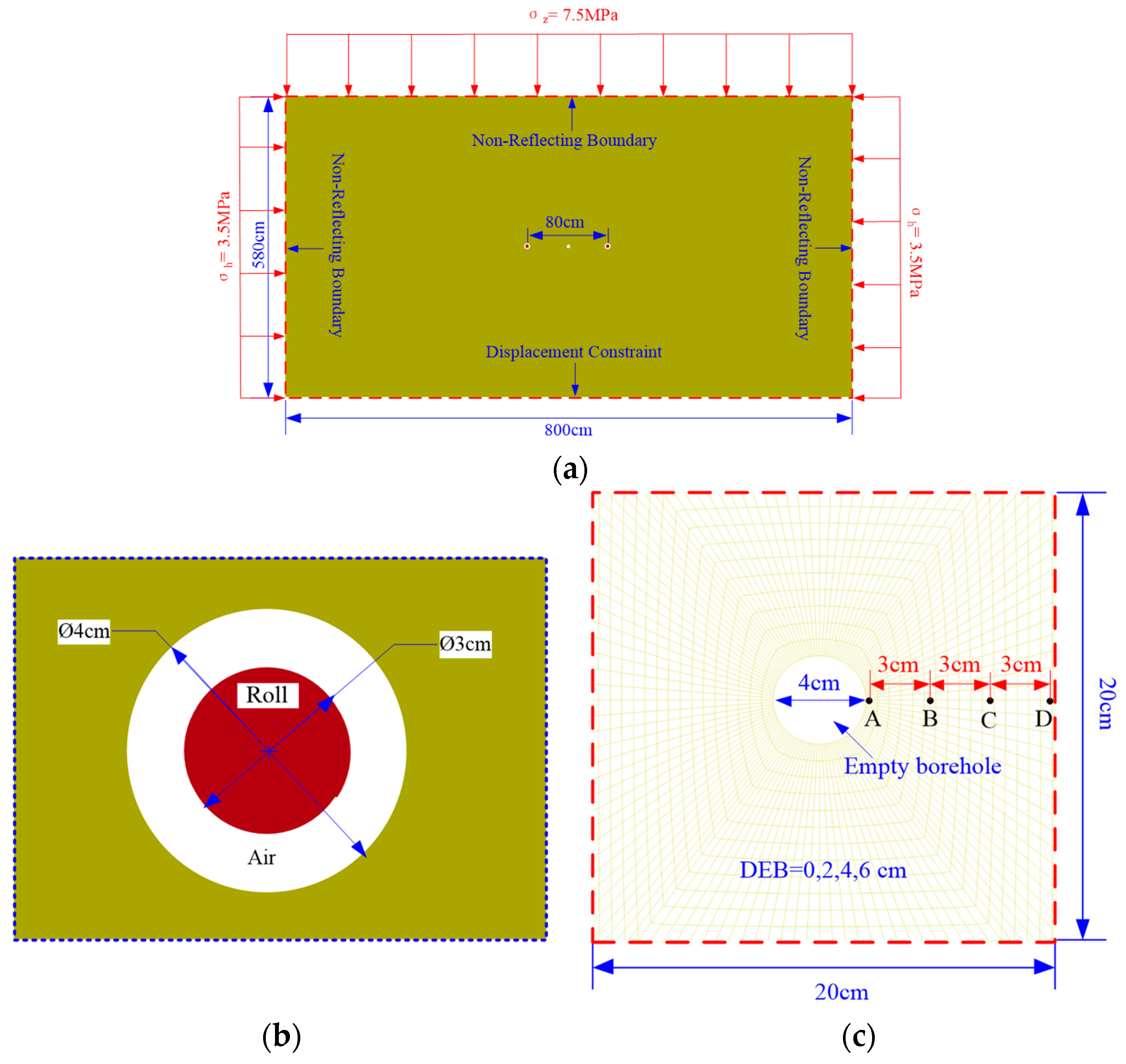
To analyze the effect of the empty borehole on rock damage under blasting loading, a numerical model with dimensions of 800 cm (in length) × 580 cm (in width) is established by the numerical modeling code LS-DYNA (Figure 3a). The borehole radius is 4 cm, and the roll diameter is 3 cm (Figure 3b). The empty borehole is in the center of the numerical model. The horizontal spacing between the empty borehole and each blasting borehole is 40 cm. To eliminate the influence of the reflected stress wave, non-reflecting boundary conditions are applied to the model. To take the influence of the in situ stress into account, the in situ stresses of 7.5 MPa, 3.5 MPa, and 3.5 MPa are applied to the top, left, and right boundaries of the model. The displacement in the bottom boundary is constrained. To analyze the influence of the empty borehole on rock mass damage, the Fortran language is used to monitor the change of the numbers of the damaged rock mass elements (in both tension and compression) around the borehole. The monitoring range is 20 cm (in length) × 20 cm (in width), as shown in Figure 3c.

5. Numerical Modeling Results

5.1. Analysis of Stress Wave Evolution

5.1.1. Stress Wave Attenuation

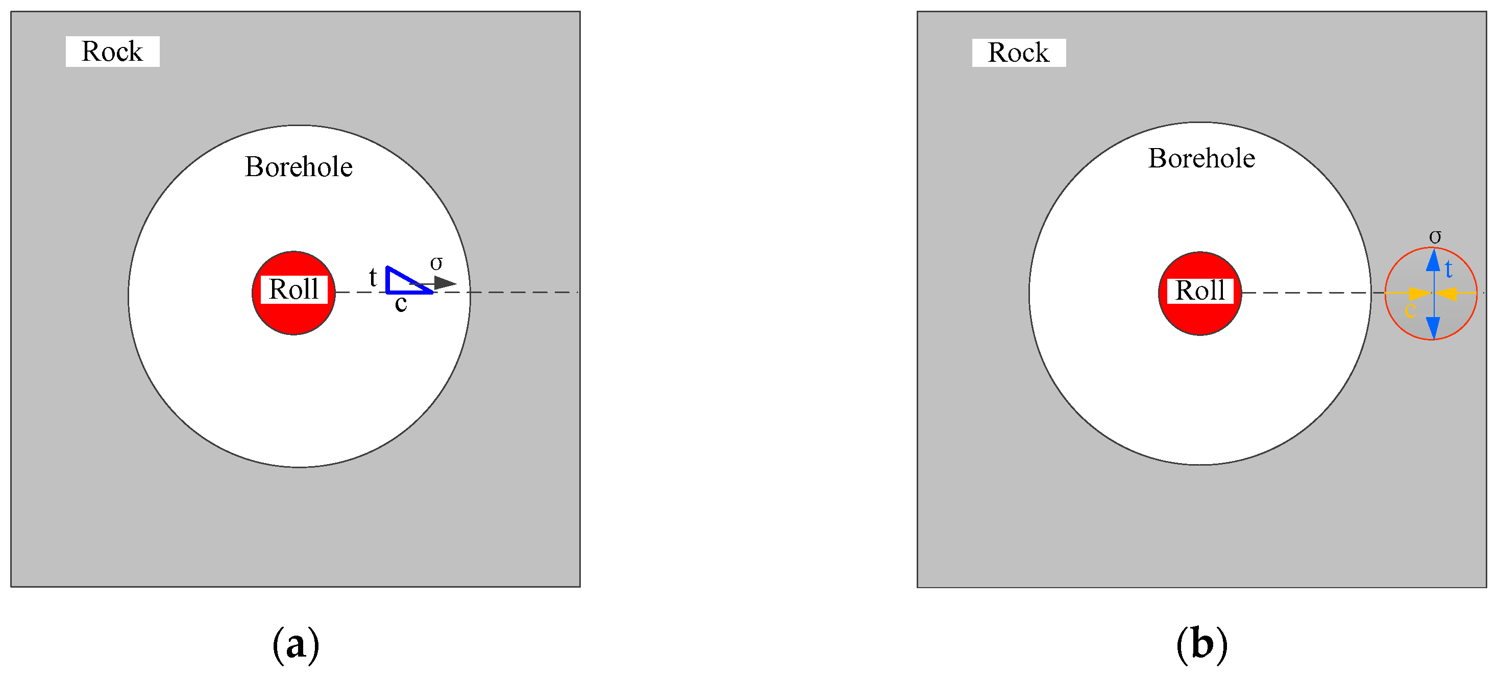
Figure 4 is a schematic of the shock wave generated after the explosion. Due to the interaction between the shock wave and the rock mass around the borehole, the shock wave is converted into the propagating impact wave in the rock mass. The impact wave in the rock mass can be decomposed into the radial compressive component and the tangent tensile component, as shown in Figure 4.
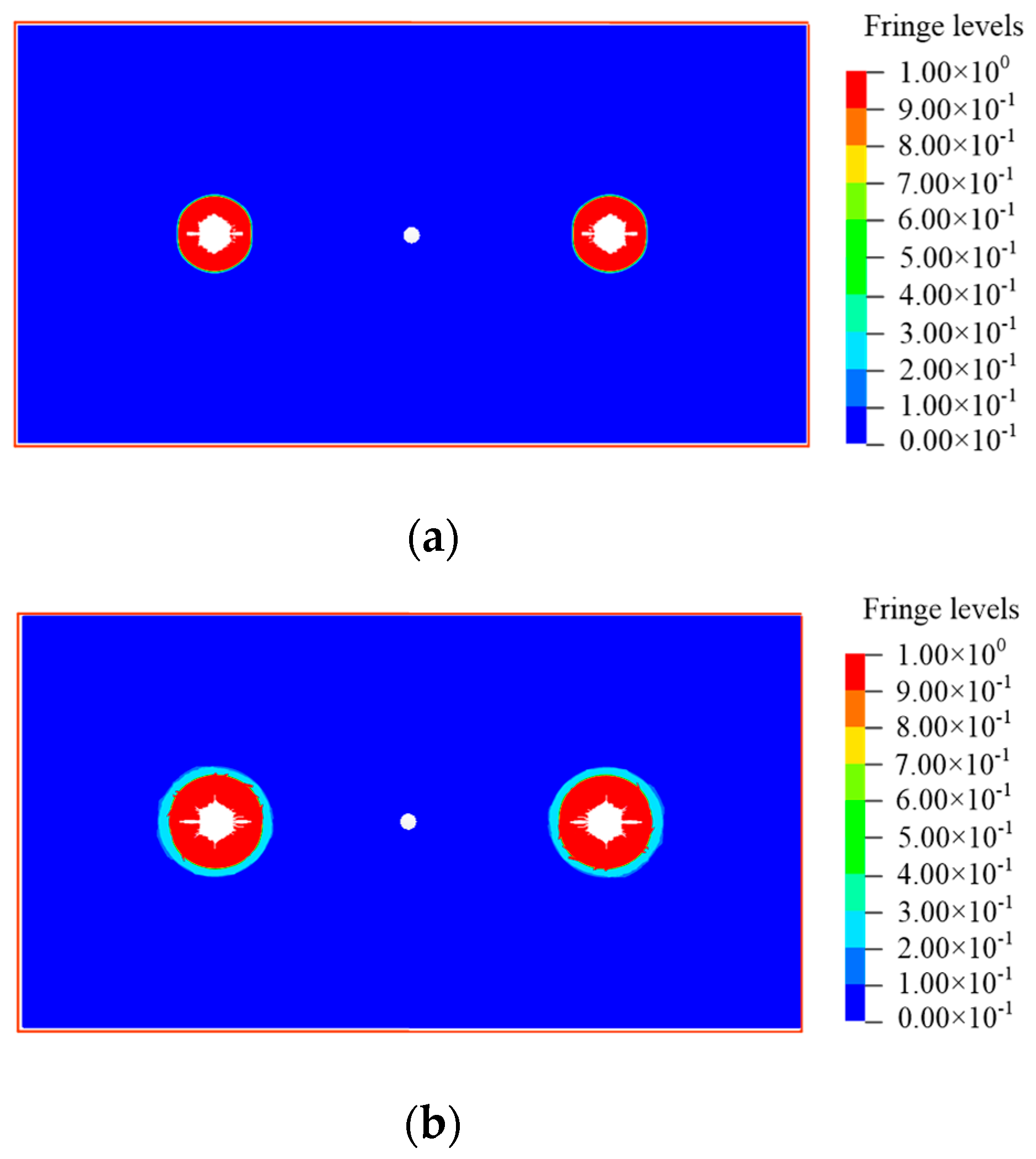
When the radial compressive component of the impact wave in the rock mass exceeds the rock compressive strength, the rock mass damages in compression and fractures are generated (Figure 5a). The impact wave transmits along the radial direction of the borehole, and its energy is attenuated by the interaction with the rock mass. Then, the impact wave is converted into the stress wave that keeps propagating in the rock mass. The radial compressive component of the impact wave is less than the compressive strength of the rock mass, while the tangent tensile component is higher than rock mass tensile strength. This leads to the tensile damage in the rock mass and further propagation of the fractures (Figure 5b).

5.1.2. Stress Wave Reflection

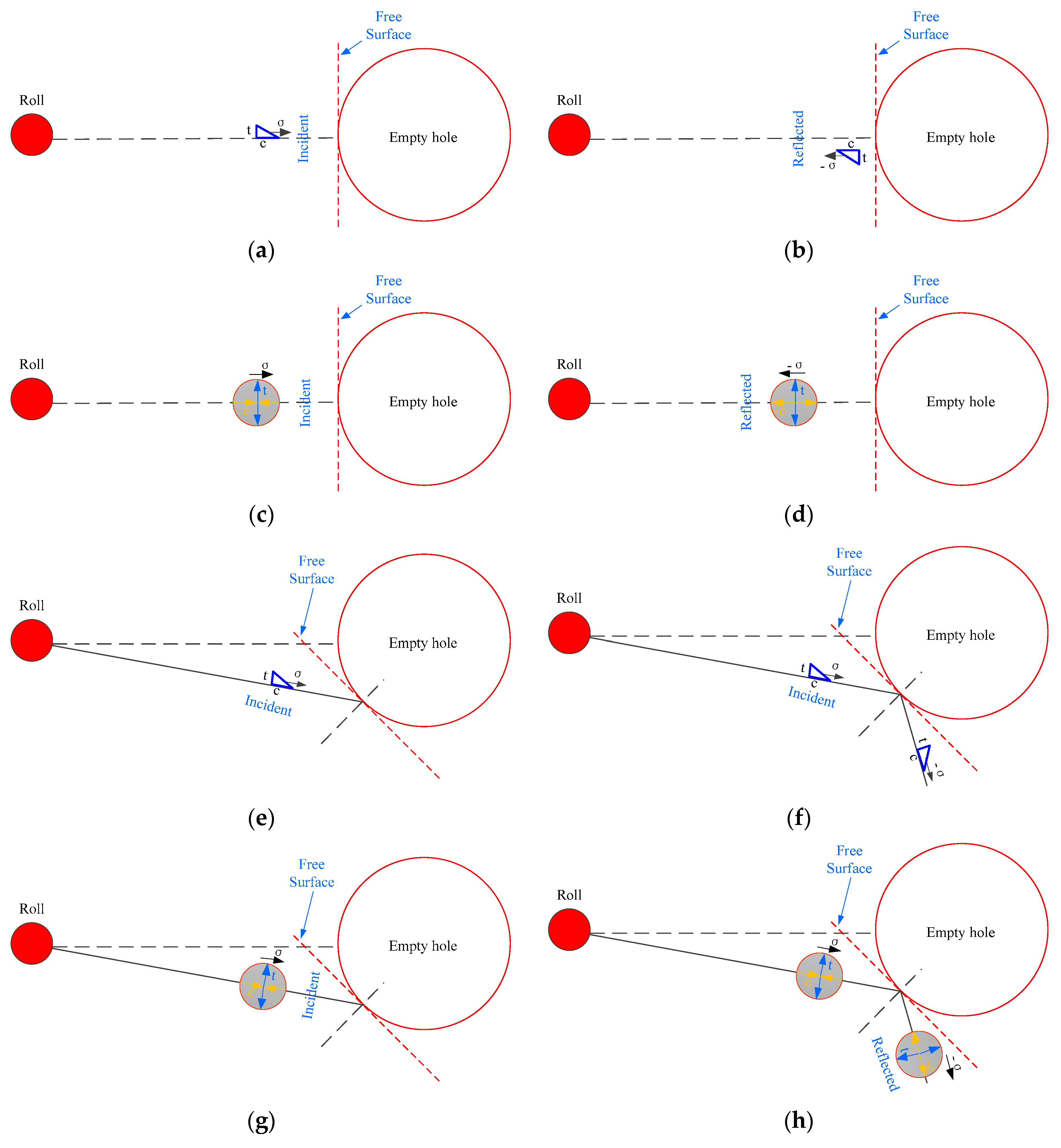
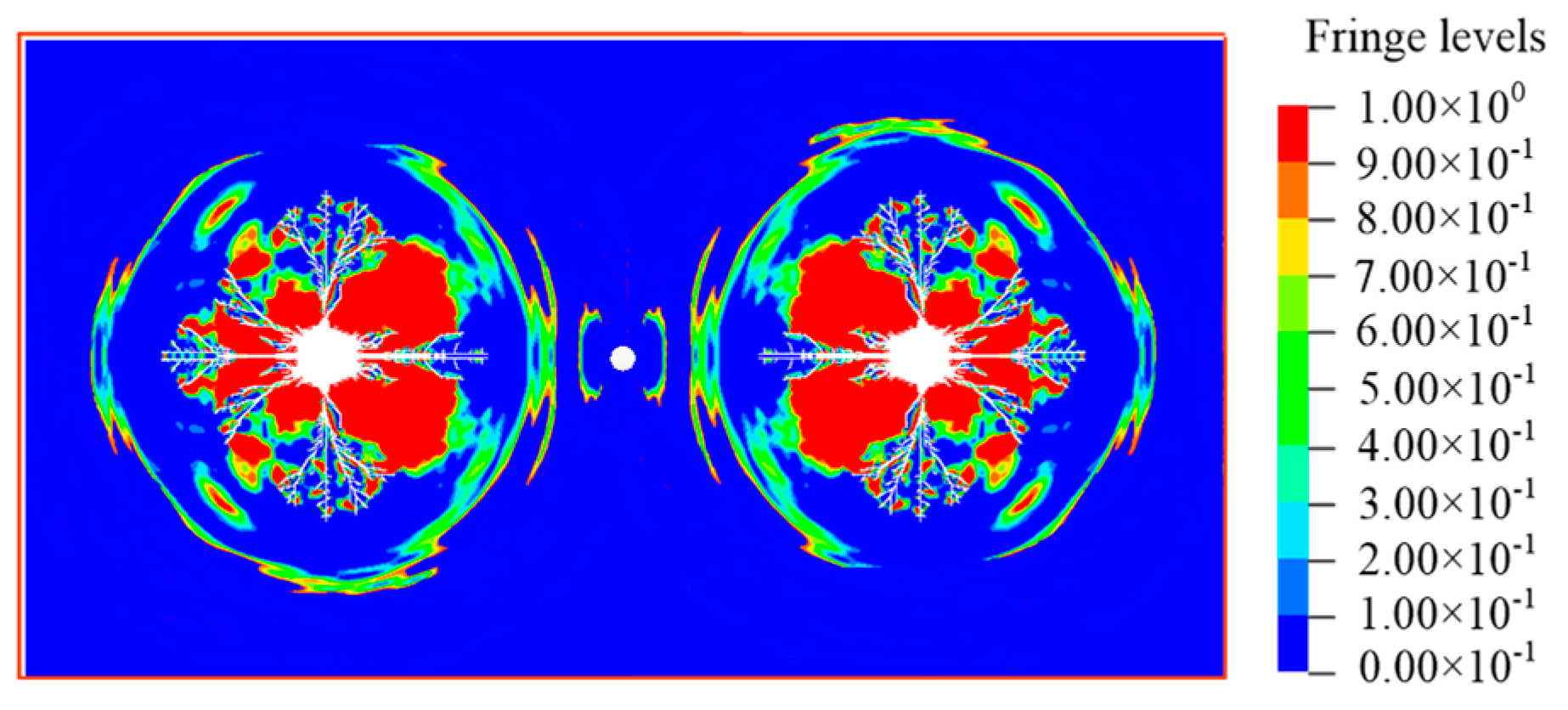
When the stress wave propagates to the empty borehole, the stress wave reflects at the free surface of the empty borehole, which changes the propagation direction of the stress wave. Two main reflection modes exist when the stress wave reaches the borehole free surface, including the normal incidence and the oblique incidence. The normal incidence mode compressive stress wave reflects at the empty borehole free surface, and its phase (direction) rotates by 180°. In this case, the compressive stress wave is transformed into the tensile stress wave (Figure 6a,b). Moreover, the radial compressive component of the incidence compressive wave is converted into the radial tensile component of the tensile wave, and the incidence tangent tensile component is transformed into the tangent tensile component of the tensile stress wave (Figure 6c,d). The compressive wave could also reflect in the oblique incidence mode (Figure 6e,f). In this situation, the reflection process is more complicated. When the oblique incidence mode stress wave reflects at the empty borehole free surface, the radial compressive component of the incidence compressive wave is converted into the radial tensile component of the tensile wave, and the incidence tangent tensile component is transformed into the tangent tensile component of the tensile stress wave (Figure 6g,h). After the tip of the compressive stress wave reflects at the empty borehole free surface, the reflected tensile stress wave forms. Figure 7 is the damage zone induced by the reflected tensile stress wave.

5.1.3. Stress Wave Superimposition

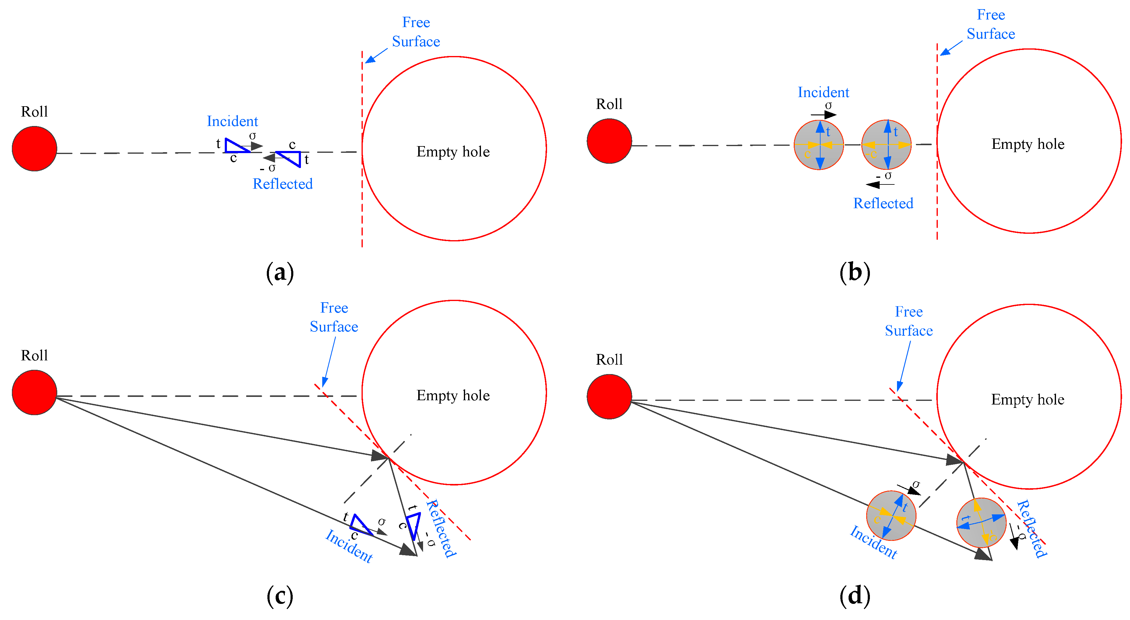
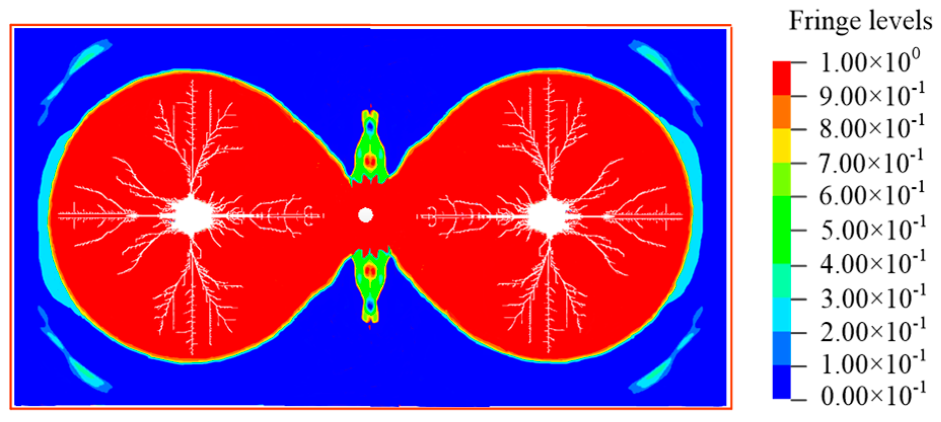
Figure 8a indicates that the normal incidence mode compressive stress wave superimposes on the reflected tensile stress wave in the horizontal direction when they encounter. Figure 8b shows that the tensile component of the incidence stress wave superimposes on the tensile component of the tensile stress wave in the vertical direction. Consequently, the superimposed stress wave creates a higher tensile stress. As shown in Figure 8c,d, with the propagation of the incidence stress wave, superimposition also occurs in the oblique incidence mode stress wave. The tangent tensile component and the radial compressive component of the stress wave deviate at another free surface. The directions of the tangent tensile components of the incidence stress wave and the reflected stress wave are inconsistent with each other. Hence, the tensile stress induced by the superimposition of the oblique incidence mode wave is less than that generated by the superimposition of the normal incidence mode wave. Due to the superimposition of the stress wave around the empty borehole, large tensile stresses occur in the superimposition zone. This leads to obvious tensile damage in the rock mass around the empty borehole (Figure 9).

5.1.4. Influence of Empty Borehole

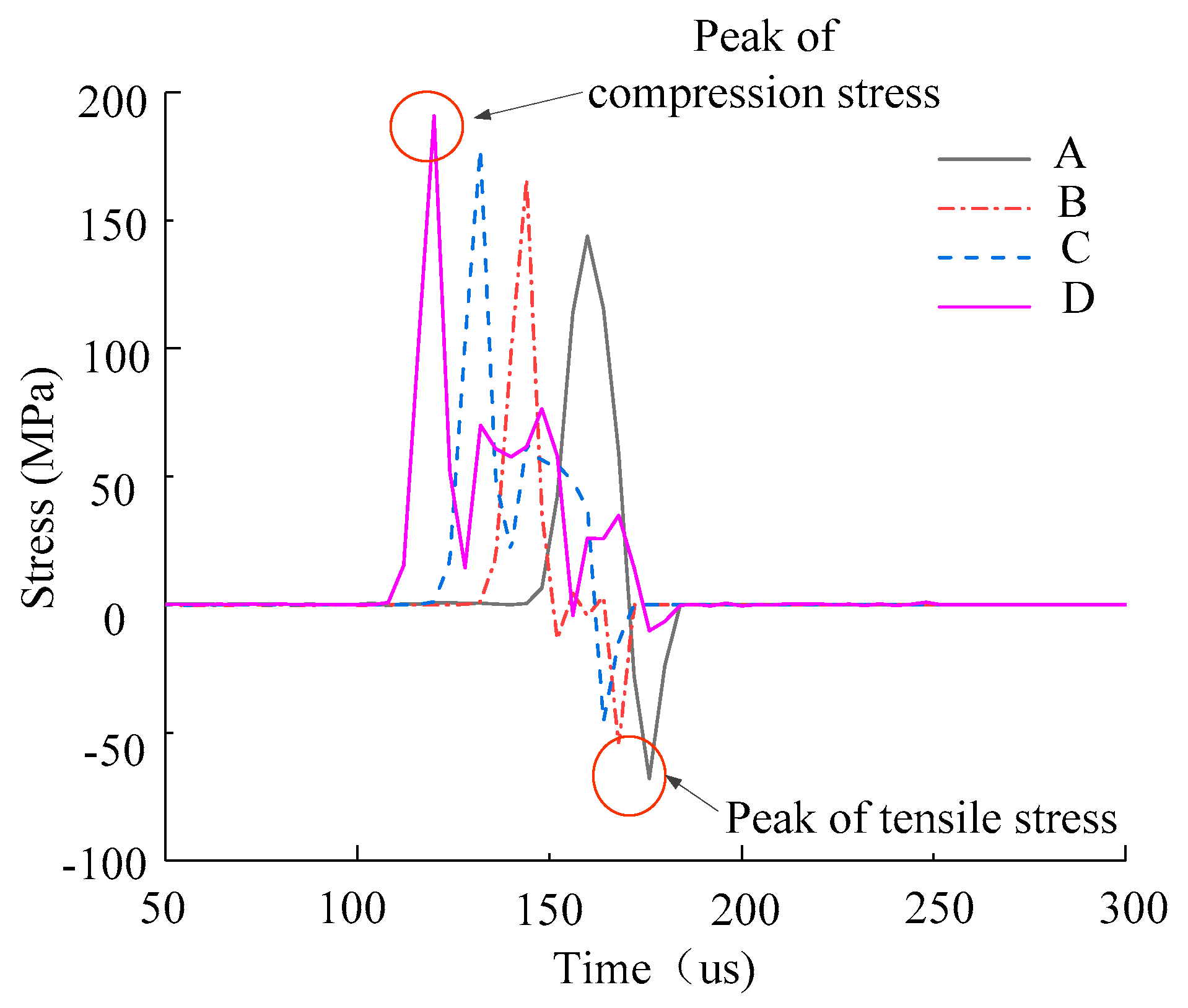
Figure 10 shows the stress change curves of different monitoring elements. The stress distributions of different elements almost exhibit the same tendency. Each element sustains both the compressive stress and the tensile stress. The relative locations of Monitoring Points A, B, C, and D to the empty borehole are shown in Figure 3c. The maximum compressive stress of the monitoring point sustains increases as the distance between the monitoring point and the empty borehole increases. The compressive stresses at Monitoring Points A, B, and C fluctuate with time after they reach the maxima, while the stresses at these monitoring points decreases rapidly to 0 once they reach the maximum tensile stresses, respectively. This suggests that the monitoring element completely fails due to the tensile stress. The maximum tensile stress at Monitoring Point A (which is closest to the empty borehole compared with Monitoring Points B and C) is 28.3% and 42.8% higher than that at Monitoring Points B and C, respectively. The results show that the empty borehole free surface induces the reflection of the incidence compress stress wave and forms the reflected tensile wave. When the reflected tensile wave transmits to Monitoring Point A, the superimposition of the incidence wave and the reflected wave notably enhances the tensile stress at Monitoring Point A and leads to the damage of the element. Therefore, the empty borehole can significantly increase the tensile stress in the rock mass element.
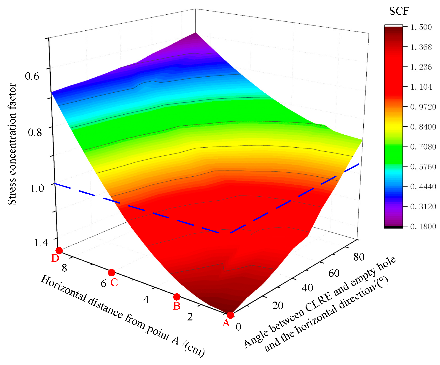
The stress concentration factors (SCF = σψρ) of the rock mass elements around the empty borehole are given in Figure 11. The stress concentration factor increases as the distance between the element and the empty borehole decreases. The stress concentration factor at Monitoring Point A reaches the maximum (1.52), and the stress concentration factor at Monitoring Point C is 1 (Figure 11). This coincides with the maximum tensile stresses at the monitoring points in Figure 10. This indicates that the empty borehole can effectively increase the tensile stress in the rock mass element, and the maximum tensile stress that the element sustains increases with the decreasing distance between the element and the empty borehole. Along the circumferential direction of the empty borehole (approximately 0° to 90°), the stress concentration factor of the element decreases as the angle between the horizontal line and the line connecting the element and the borehole center increases. This shows that when the stress wave strikes the empty borehole, the tensile stress in the borehole wall element decreases as the incidence angle increases. The tensile stress reaches the maximum when the wave strikes in the normal incidence mode.

5.2. Damage Evolution around an Empty Borehole with 2 cm Diameter

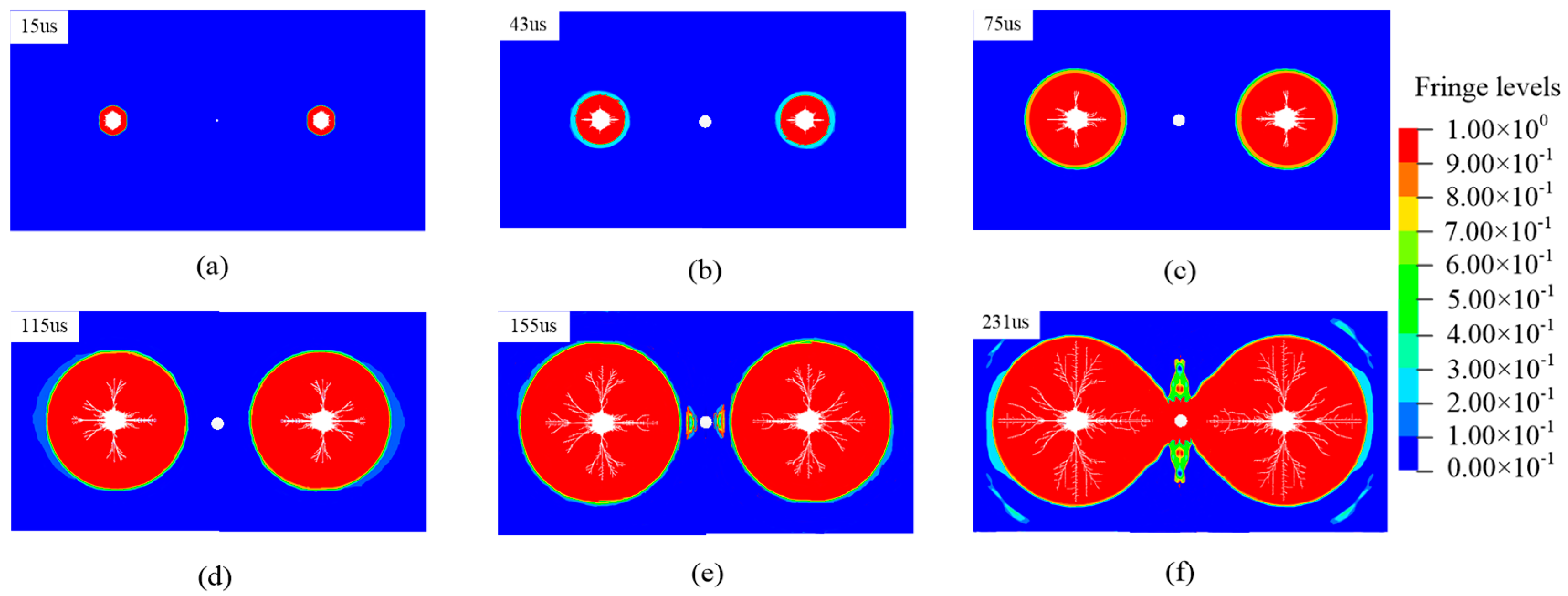
After the explosive detonates, the propagation of the impact wave or the stress wave is divided into three main stages, including the attenuation stage, the reflection stage, and the superimposition stage. The stress state in the rock mass varies in different stages, and hence the rock mass damage evolution consists of different processes. Figure 12 shows the rock mass damage evolution processes around an empty borehole with 2 cm diameter. Fractures initiate in the rock mass around the blasting boreholes due to compressive damage induced by the impact wave (Figure 12a,b). With the transmission of the impact wave, the fractures induced by compressive damage propagate to the zone in which the radial compressive component is lower than the rock mass strength. This forms a compressive damage zone. As shown in Figure 12c, the impact wave transmits in the rock mass. It is attenuated and becomes the stress wave. When the compressive stress is lower than the tensile strength of the rock, no compressive damage occurs in the rock mass. Nevertheless, the rock is a brittle material with low tensile strength. In this situation, the tangent tensile stress component of the stress wave is higher than the tensile strength of the rock mass, resulting in the fractures in the rock mass due to tensile damage. When the tensile damage develops to the degree in which the tangent tensile component is lower than the tensile strength of the rock mass, a tensile damage zone forms outside of the compressive damage zone. As shown in Figure 12d,e, when the stress wave transmits to the empty borehole free surface, the compressive wave reflects at the free surface and forms the tensile wave. The compressive wave superimposes on the tensile wave nearby the empty borehole, leading to a notable increase of the tensile stress component. If the superimposed tensile stress exceeds the tensile strength of the rock mass, the superimposed tensile wave induces tensile damage and generates the fractures propagating toward the rock mass (Figure 12f). Finally, the fractures stretch through the empty borehole and the blasting boreholes (Figure 12f).
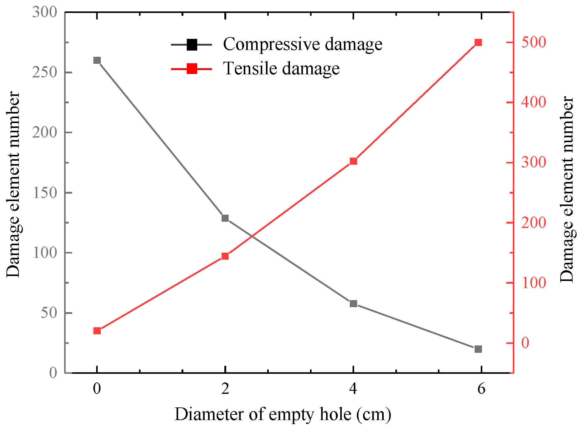
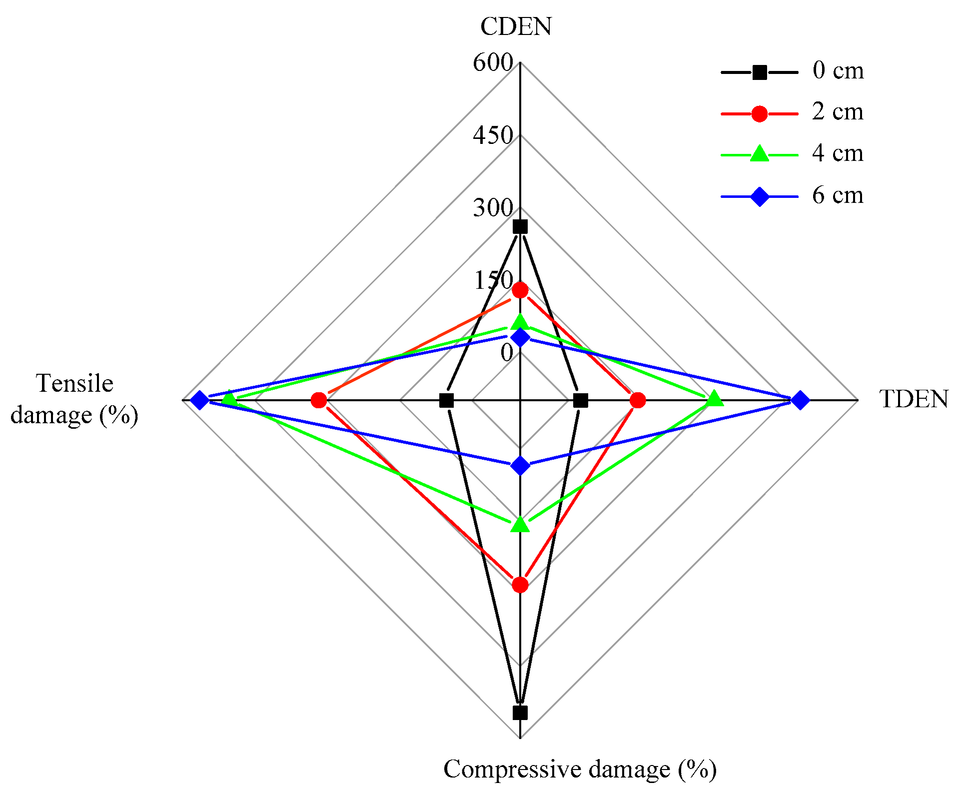
The Fortran language is used to monitor the damage type of the element and record the corresponding element number, as shown in Figure 13. Damaged elements occur 100 μs after the detonation, and the damage type is compressive damage. This indicates that the compressive stress that the element sustains is higher than the compressive strength. When the detonation time (t) increases to about 140 μs of the stress attenuation stage, tensile damage elements occur. When the detonation time ranges from 140 to 230 μs of the stress reflection stage, the numbers of both the tensile damage elements and the compressive damage elements increase. When the detonation time increases from 230 to 400 μs of stress superimposition, the number of the compressive damage elements and the tensile damage elements increases dramatically and then becomes steady. With the increase of the empty borehole diameter (e.g., 0 cm, 2 cm, 4 cm,6 cm), the number of the tensile damage elements increases gradually, and the number of compression damage elements decreases gradually. The reason is that the empty borehole can notably enhance the tensile stresses in the rock mass elements around the empty borehole (Figure 10). Hence, the existence of the empty borehole significantly changes the stress state in the rock mass element and increases the number of the tensile damage elements. This suggests that tensile damage dominates the fracture propagation around the empty borehole, while it is consistent with the stress states in the monitoring elements (Figure 10).

5.3. Damage Evolution around Empty Boreholes with Different Diameters

The number of the elements tensile damage sustaining increases with an increasing empty borehole diameter, while the number of the elements sustaining compressive damage decreases gradually (Figure 14). The reason is that the existence of the empty borehole free surface enhances the tensile stress in the rock mass element. As shown in Figure 15, with the increase of the empty borehole diameter, the ratio of the compressive damaged elements to the overall damaged elements decreases dramatically. The main reason is that the curve surface (free surface) characteristic provided by the empty borehole increases the tensile stress in the rock mass. Meanwhile, the damaged rock mass elements around the empty borehole are mainly the tensile damage types.

6. Conclusions

A tension–compression damage model is established based on the rock mass damage type in this paper. The model is successfully incorporated into the numerical modeling code LS-DYNA. Constant in situ stresses are applied to the model in order to investigate the influence of the empty borehole on the damage evolution processes of the rock mass. The Fortran language is used to monitor the variation of the numbers of the tensile damaged elements and the compressive damaged elements around the empty borehole. The following conclusions are made.
(1)
The empty borehole can significantly enhance the tensile stresses and the stress concentration factors in the rock mass elements nearby the empty borehole. The maximum tensile stress at the monitoring point increases as the distance between the monitoring point and the empty borehole decreases. The stress concentration factor in the rock mass nearby the empty borehole decreases as the angle between the horizontal line and the line connecting the element and the empty borehole centre increases.
(2)
The existence of the empty borehole increases the number of the tensile damage elements. The tensile damage dominates the damage of the rock mass around the empty borehole. The incidence compressive stress wave reflects at the empty borehole free surface and is converted into the tensile stress wave. The fracture initiation in the rock mass nearby the empty borehole is dominated by the tensile stress wave.
(3)
The damage zone extends as the empty borehole diameter increases, and the rock mass nearby the empty borehole mainly damages in tension. With the increase of the empty borehole diameter, the number of the compressive damaged elements decreases non-linearly, and the number of the tensile damaged elements increases almost linearly. As the empty borehole diameter increases, the ratio of the compressive damaged elements decreases and the ratio of the tensile damaged elements increases.

Author Contributions

Investigation, N.M.; writing—original draft preparation, J.B.; data curation and paper writing, Y.C.; writing—review and editing, X.W.; supervision, W.W.; project administration, B.W. and S.L. All authors contributed equally in this paper. All authors have read and agreed to the published version of the manuscript.

Funding

The work of this paper is financially supported by the Fundamental Research Funds for the Central Universities (2018ZDPY02).

Acknowledgments

We would like to thank Bai Jianbiao for providing technical support for the study.

Conflicts of Interest

The authors declare no conflict of interest.

Abbreviations

A, B, R1, R2 and ωparameters of JWL equation of state
Pbpressure applied to the borehole wall
Eiinitial internal energy density of the detonation product
c, pcontants of Kinematic Hardening relation
βhardening coefficient
Epthe kinematic hardening modulus
Etanthe tangent modulus
E0Young’s modulus
F(σ)strength function
F,F0Weibull distribution parameters
Srock strength
Mthe total number of internal micro units in rock micro element
Mfthe number of internal micro units in rock micro element
Q(F)probability density distribution function
Vrelative volume of the detonation product
ε ˙ strain rate
μPoisson’s ratio
σ1maximum principal stress
σ3minimum principal stress
σsyield stress
σtsdynamic tensile strength
σcsdynamic compressive strength
Dtsdamage parameters of tensile stress
Dcsdamage parameters of compressive stress
At, Btmaterial constants
σ i j * trial stress tensor
σ i j n , σ i j n 1 stress tensor with damage from the previous step
σ i j n ¯ stress tensor
Gshear modulus
S i j n , S i j n 1 deviatoric stress tensor
εvvolumetric strain
ε e f f p effective plastic strain
d ε v volumetric strain increment
d ε e f f p effective plastic strain increment
Δ ε k l the incremental strain tensor
S i j * trial deviatoric stress tensor
m t s n total number of element damage with tensile stress at n step
m t s i number of element damage with tensile stress at i step
n c s n total number of element damage with compressive stress at n step
n c s i number of element damage with compressive stress at i step
Dsdamage variable
σzvertical stress
σhhorizontal stress
σψtangential tensile stress
σρblast-induced radial stress

References

  1. Adhikari, G.R.; Babu, A.R.; Balachander, R.; Gupta, R.N. On the application of rock mass quality for blasting in large underground chambers. Tunn. Undergr. Space Technol. 1999, 14, 367–375. [Google Scholar] [CrossRef]
  2. Wang, F.T.; Tu, S.H.; Yuan, Y.; Feng, Y.F.; Chen, F.; Tu, H.S. Deep-hole pre-split blasting mechanism and its application for controlled roof caving in shallow depth seams. Int. J. Rock Mech. Min. Sci. 2013, 64, 112–121. [Google Scholar] [CrossRef]
  3. Xu, N.W.; Li, T.B.; Dai, F.; Zhang, R.; Tang, C.A.; Tang, L.X. Microseismic Monit-oring of Strainburst Activities in Deep Tunnels at the Jinping II Hydropower Station, China. Rock Mech. Rock Eng. 2016, 49, 981–1000. [Google Scholar] [CrossRef]
  4. Yue, Z.W.; Guo, Y.; Wang, X.; Yang, H.B.; Han, T.X. Influence of empty hole shape on direct-ional fracture controlled blasting of rock. Rock Soil Mech. 2016, 37, 376–382. [Google Scholar] [CrossRef]
  5. Bian, K.F.; Li, H.B.; Liu, Y.Q. Numerical Simulation for the Damping Effect of Empty Holes on Blasting Vibration. Adv. Mater. Res. 2014, 1490–1495. [Google Scholar] [CrossRef]
  6. Amiri, H.S.; Murthy, V.M.S.R. Optimising blast pulls and controlling blast induced excavation damage zone in tunnelling through varied rock classes. Tunn. Undergr. Space Technol. 2019, 85, 307–318. [Google Scholar] [CrossRef]
  7. Liu, J.; Guo, X.Q.; Liu, Z.J. Pressure field investigation into oil&gas wellbore during perforating shaped charge explosion. J. Pet. Sci. Eng. 2019, 172, 1235–1247. [Google Scholar]
  8. Cho, S.H.; Nakamura, Y.; Mohanty, B.; Yang, H.S.; Kaneko, K. Numerical study of fracture plane control in laboratory-scale blasting. Eng. Fract. Mech. 2008, 75, 3966–3984. [Google Scholar] [CrossRef]
  9. He, C.L.; Yang, Y. Experimental and numerical investigations of dynamic failure process in rock under blast loading. Tunn. Undergr. Space Technol. 2018, 83, 552–564. [Google Scholar] [CrossRef]
  10. Ma, G.W.; An, X.M. Numerical simulation of blasting-induced rock fractures. Int. J. Rock Mech. Min. Sci. 2008, 45, 966–975. [Google Scholar] [CrossRef]
  11. Chen, B.B.; Liu, C.Y.; Yang, J.X. Design and Application of Blasting Parameters for Presplitting Hard Roof with the Aid of Empty-Hole Effect. Shock Vib. 2018, 2018, 1–16. [Google Scholar] [CrossRef] [Green Version]
  12. Taylor, L.M.; Chen, E.P.; Kuszmaul, J.S. Microcrack-induced damage accumulation in brittle rock under dynamic loading. Comput. Method. Appl. Mech. Eng. 1986, 55, 301–320. [Google Scholar] [CrossRef]
  13. Kuszmaul, J.S. A new constitutive model for fragmentation of rock under dynamic loading. In Proceedings of the 2nd International Symposium on Rock Fragmentation by Blasting, Columbia, SC, USA, 23 August 1987; pp. 412–423. [Google Scholar]
  14. Barton, N.; Bandis, S.; Bakhtar, K. Strength deformation and conductivity coupling of rock joints. Int. J. Rock Mech. Min. Sci. Geomech. Abstr. 1985, 22, 121–140. [Google Scholar] [CrossRef]
  15. Furlong, J.R.; Alme, M.L.; Rajendran, A.M. Numerical modeling of ceramic penetration experiments. In Proceedings of the Fourth TACOM Armor Coordinating Conference for Light Combat Vehicles, Monterey, CA, USA, 31 March 1988. [Google Scholar]
  16. Wu, C.; Lu, Y.; Hao, H. Numerical prediction of blast-induced stress wave from large-scale underground explosion. Int. J. Numer. Anal. Methods Geomech. 2004, 28, 93–109. [Google Scholar] [CrossRef]
  17. Hu, Y.G.; Lu, W.B.; Chen, M.; Yan, P.; Zhou, C.B. Comparison of damage evolution process of high rock slope excavated by different methods. Chin. J. Rock Mech. Eng. 2013, 32, 1176–1184. (In Chinese) [Google Scholar]
  18. Saharan, M.R.; Mitri, H.S. Numerical procedure for dynamic simulation of discrete fractures due to blasting. Rock Mech. Rock Eng. 2007, 41, 641–670. [Google Scholar] [CrossRef]
  19. Banadaki, M.D.; Mohanty, B. Numerical simulation of stress wave induced fractures in rock. Int. J. Impact Eng. 2012, 40, 16–25. [Google Scholar] [CrossRef]
  20. Zhu, W.C.; Wei, J.; Zhao, J.; Niu, L.L. 2D numerical simulation on excavation damaged zone induced by dynamic stress redistribution. Tunn Undergr. Space Technol. 2014, 43, 315–326. [Google Scholar] [CrossRef]
  21. Autlo, J. Characterization of the Excavation Disturbance Caused by Boring of the Experimental Full Scale Deposition Holes in the Research Tunnel at Olkiluoto; Posiva-96-09; Posiva: Helsinki, Finland, 1996. [Google Scholar]
  22. Bäckblom, G.; Martin, C.D. Recent experiments in hard rock to study the excavation response: Implications for the performance of a nuclear waste geological repository. Tunn Undergr. Space Technol. 1999, 14, 377–394. [Google Scholar] [CrossRef]
  23. Kwon, S.; Lee, C.S.; Cho, S.J.; Choc, S.J.; Jeonb, S.W.; Cho, W.J. An investigation of the excavation damaged zone at the KAERI underground research tunnel. Tunn. Undergr. Space Technol. 2009, 24, 1–13. [Google Scholar] [CrossRef]
  24. Abuov, M.G.; Aitaliev, S.M.; Ermekov, T.M.; Zhanbyrbaev, N.B.; Kayupov, M.A. Studies of the effect of dynamic processes during explosive break-out upon the roof of mining excavations. Sov. Min. Sci. 1998, 24, 581–590. [Google Scholar] [CrossRef]
  25. Cai, M. Influence of stress path on tunnel excavation response–numerical tool selection and modeling strategy. Tunn. Undergr. Space Technol. 2008, 23, 618–628. [Google Scholar] [CrossRef]
  26. Malezhik, M.P.; Malezhik, O.P.; Chernyshenko, I.S. Photoelastic determination of dynamic crack-tip stresses in an anisotropic plate. Int. Appl. Mech. 2006, 42, 574–581. [Google Scholar] [CrossRef]
  27. Yue, Z.W.; Yang, L.Y.; Wang, Y.B. Experimental Study of Crack Propagation in Polymethyl Methacrylate Material with Double Holes under the Directional Controlled Blasting. Fatigue Fract. Eng. Mater. Struct. 2013, 36, 827–833. [Google Scholar] [CrossRef]
  28. Asprone, D.; Cadoni, E.; Prota, A.; Manfredi, G. Dynamic behavior of a Mediterranean natural stone under tensile loading. Int. J. Rock Mech. Min. 2009, 46, 514–520. [Google Scholar] [CrossRef]
  29. Zhang, Q.B.; Zhao, J. A review of dynamic experimental techniques and mechanical behavior of rock materials. Rock Mech. Rock Eng. 2014, 47, 1411–1478. [Google Scholar] [CrossRef] [Green Version]
  30. Hallquist, J.O. LS-DYNA Theory Manual; Livermore Software Technology Corporation: Livermore, CA, USA, 2006. [Google Scholar]
  31. Wang, Y. Analysis of dynamic characteristics of through-wall cracks between 2 boreholes in the directed fracture controlled blasting. Fatigue Fract. Eng. Mater. Struct. 2018, 41, 273–286. [Google Scholar] [CrossRef]
  32. Jones, N. Structural Aspects of Ship Collisions; Butterworth and Company Publishers Limited: London, UK, 2006; Chapter 11; pp. 308–337. Available online: http://refhub.elsevier.com/S0886-7798(15)30010-9/h0090 (accessed on 31 December 2019).
  33. Baker, E.L. An Explosives Products Thermodynamic Equation of State Appropriate for Material Acceleration and Overdriven Detonation: Theoretical Background and Fourmulation; Technical Report ARAED-TR-911013, US; Army Armament Research Development and Engineering Center Picatinny: Picatinny Arsenal, NJ, USA, 1991. [CrossRef]
  34. Kury, J.W.; Horning, H.C.; Lee, E.L.; Mcdonnel, J.L.; Ornellas, D.L.; Finger, M. Metal acceleration by chemical explosives. In Proceedings: Fourth Symposium (International) on Detonation / sponsored by the U. S. Naval Ordnance Laboratory in cooperation with the Office of Naval Research; University of California Libraries: Berkeley, CA, USA, 1965; pp. 3–13. [Google Scholar]
  35. Sanchidrian, J.A.; Castedo, R.; Lopez, L.M.; Segarra, P.; Santos, A.P. Determination of the JWL constants for ANFO and emulsion explosives from cylinder test data. Cent. Eur. J. Energetic Mater. 2015, 12, 177–194. [Google Scholar]
  36. Krieg, R.D.; Key, S.W. Implementation of a Time Dependent Plasticity Theory into Structural Computer Programs. Comput. Eng. Asp. 1976, 20, 125–137. [Google Scholar]
  37. Yang, R.; Bawden, W.F.; Katsabanis, P.D. A new constitutive model for blast damage. Int. J. Rock Mech. Min. Sci. Geomech. Abstr. 1996, 33, 245–254. [Google Scholar] [CrossRef]
  38. Xia, X. Study of Damage Characteristics and Safety Threshold of Rock Vibration by Blast. Institute of Rock and Soil Mechanics. Ph.D. Thesis, Chinese Academy of Sciences, Wuhan, China, 2006. [Google Scholar]
  39. Yang, J.H.; Lu, W.B.; Hu, Y.G.; Chen, M.; Yan, P. Numerical simulation of rock mass damage evolution during deep-buried tunnel excavation by drill and blast. Rock Mech. Rock Eng. 2015, 48, 2045–2059. [Google Scholar] [CrossRef]
  40. Cai, M.; Kaiser, P.K.; Tasaka, Y.; Maejima, T.; Morioka, H.; Minami, M. Generalized crack initiation and crack damage stress thresholds of brittle rock masses near underground excavations. Int. J. Rock Mech. Min. Sci. 2004, 41, 833–847. [Google Scholar] [CrossRef]
  41. Pisarenko, G.S.; Lebedev, A.A. Deformation and Strength of Materials under Complex Stress State; Naukova Dumka: Kiev, Ukraine, 1976. (In Russian) [Google Scholar]
  42. Krajcinovic, D.; Silva, M.A.G. Statistical aspects of the continuous damage theory. Int. J. Solids Struct. 1982, 18, 551–562. [Google Scholar] [CrossRef]
  43. Cao, W.G.; Fang, Z.L.; Tang, X.J. A study of statistical constitutive model for soft and damage rocks. Chin. J. Rock Mech. Eng. 1998, 17, 628–633. [Google Scholar]
  44. Meng, N.K.; Chen, Y.; Bai, J.B.; Wang, X.Y.; Wu, W.D.; Wu, B.W. Numerical simulation of directional fracturing by shaped charge blasting. Energy Sci. Eng. 2020, 1–16. [Google Scholar] [CrossRef]
  45. Grady, D.E.; Kipp, M.E. Continuum modeling of explosive fracture in oil shale. Int. J. Rock Mech. Min. Sci. Geomech. Abstr. 1980, 17, 147–157. [Google Scholar] [CrossRef]
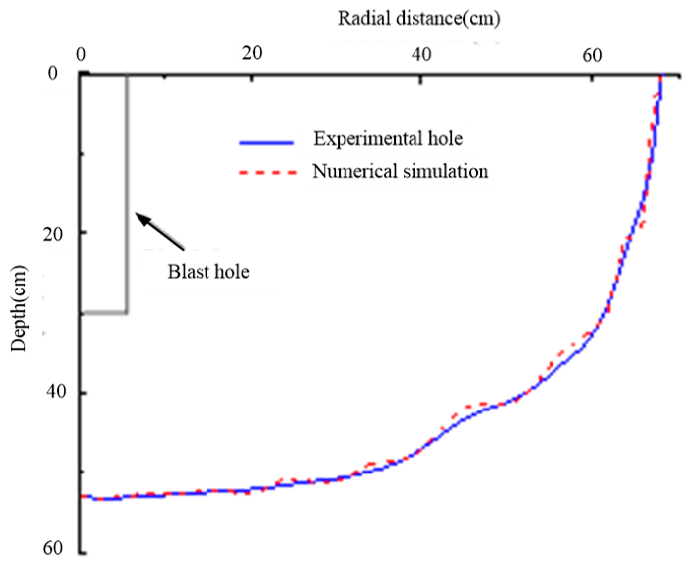
Figure 1. Comparison between the numerical modeling results and the experimental testing results.
Energies 13 00756 g001
Figure 2. Calculation flowchart of the Kinematic Hardening model.
Energies 13 00756 g002
Figure 3. Schematic of numerical model: (a) layout of numerical model; (b) Schematic diagram of the borehole size; (c) layout of monitoring points and monitoring range. PS: DEB = diameter of empty hole.
Energies 13 00756 g003
Figure 4. Schematic of shock wave: (a) Shock wave induced by explosion; (b) the components of shock wave. PS: ‘c’ - radial compression; ‘t’ - tangent tension.
Energies 13 00756 g004
Figure 5. Damage around the blasting boreholes: (a) compressive damage; (b) tensile damage.
Energies 13 00756 g005
Figure 6. Reflection processes of stress wave at the free surface of the empty borehole: (a) The normal incidence of the stress wave; (b) the reflection of the normal incidence stress wave; (c) the components of the normal incidence stress wave; (d) the components of the normal reflected stress wave; (e) the oblique incidence of the stress wave; (f) the oblique reflection of the stress wave; (g) the components of the oblique incident stress wave; (h) the components of the oblique reflected stress wave. PS: ‘σ’ indicates incidence of stress wave; ‘-σ’ indicates reflection of stress wave.
Energies 13 00756 g006
Figure 7. Damage zones caused by the reflected tensile waves.
Energies 13 00756 g007
Figure 8. Superimposition process of stress waves: (a) Encounter of parallel waves; (b) superimposition of parallel waves; (c) encounter of oblique waves; (d) superimposition of oblique waves.
Energies 13 00756 g008
Figure 9. Damage evolution of empty borehole due to the superimposition of stress waves.
Energies 13 00756 g009
Figure 10. Stress–time curves at different monitoring points with various distances to the empty borehole.
Energies 13 00756 g010
Figure 11. Stress concentration factor of rock mass around empty borehole.
Energies 13 00756 g011
Figure 12. Damage evolution processes of rock mass around empty borehole with 2 cm diameter: (a) 15 μs; (b) 43 μs; (c) 75 μs; (d) 115 μs; (e) 155 μs; (f) 231 μs.
Energies 13 00756 g012
Figure 13. Number of damaged elements in the rock mass around the empty borehole: (a) Compressive damaged elements number; (b) Tensile damaged elements number.
Energies 13 00756 g013
Figure 14. Number of damaged elements around empty boreholes with different diameters.
Energies 13 00756 g014
Figure 15. Multivariate analysis of empty boreholes with different diameters. (CDEN = compressive damage element number; TDEN = tensile damage element number).
Energies 13 00756 g015
Table 1. Properties of explosive and Jones–Wilkens–Lee (JWL) state equation.
ρ0/(g.cm−3)D/(m.s−1)A/(GPa)B/(GPa)R1R2ωEi/(GPa)
10003600214.4000.1824.2000.9000.1504.192
Table 2. Mechanical parameters of air in the model.
ρ0/(g.cm−3)C4C5
1.29 × 10−30.040.04