Article

Novel Uninterruptible Phase-Separation Passing and Power Quality Compensation Scheme Based on Modular Multilevel Converter for Double-Track Electrified Railway

School of Mechanical Electronic and Information Engineering, China University of Mining & Technology (Beijing), Beijing 100083, China
*
Author to whom correspondence should be addressed.
Energies 2020, 13(3), 738; https://doi.org/10.3390/en13030738
Submission received: 22 December 2019 / Revised: 31 January 2020 / Accepted: 3 February 2020 / Published: 7 February 2020

Abstract

:
Over-voltage and over-current problems of locomotives when passing phase separation and negative sequence current penetration seriously influence the safety of double-track electrified railway and public power systems. In order to solve these problems, this paper proposes a novel uninterruptible power supply phase separation passing and power quality compensation (UPSP-PQC) scheme for double-track electrified railway. Three working modes of UPSP-PQC are put forward, including uninterruptible phase separation passing mode, power quality compensation mode and uninterruptible phase separation passing priority, and power quality compensation optimum mode. A three-leg modular multilevel converter (MMC) topology of UPSP-PQC is proposed and the corresponding control strategy has been studied. PSCAD/EMTDC simulation is performed to verify the correctness and effectiveness of the proposed scheme and its control method.

1. Introduction

In recent years, double-track electrified railways in China have been developing towards the direction of high speed and heavy haul. Single phase railway locomotives are three-phase unbalanced loads from the point of a public power system (PPS) and will lead to negative sequence current penetration into PPS [1,2,3]. A negative sequence current will greatly threaten the safe operation of electrical machines and power systems. Penalties, including extra charges and terminating electricity supply, can be executed for negative sequence current problems, according to the standard GB/T 15543-2008 in China. In order to reduce the imbalance, alternate phase sequence connection to PPS is widely adopted among traction substations [4].
On the one hand, the alternate phase sequence connection from traction substation to PPS determines that there must exist electrical phase separations (PS) [5] between adjacent traction feeders. Existing automatic PS schemes can realize power supply transition [6] between two feeders through operations of circuit breakers on ground or breakers in a locomotive. When the locomotive passes PS, it is inevitable to undergo a 100 ms process of power loss and recovery. Serious over-voltage and over-current problems will arise during this process, which strictly restricts the safe and reliable operation of high-speed and heavy-haul railways. The over-voltage of four times rated value happened in the railway line from Wuwei to Jiayuguan, which caused the insulation breakdown of electrical equipment in the locomotive [7]. The overcurrent of two times rated value arose in the transformer of the locomotive, and the normal operation of speed sensor in the locomotive was interfered with. On the other hand, although alternate phase sequence connection can decrease the negative current flowing into PPS to some extent, negative sequence current cannot be completely removed. With the exponentially increasing traction load, negative sequence current is becoming increasingly prominent.
Therefore, a novel traction power supply scheme needs to be developed for electrified railways in China, which can not only solve the transient hazards during locomotive passing PS, but also realize power quality compensation of traction substation [8,9]. In order to solve the problem of over-voltage and over-current, [10] proposes to combine resistance with the vacuum circuit breaker on the ground so as to accelerate the attenuation of over-voltage and over-current. However, it cannot reduce the amplitude of over-voltage and over-current. H. Hu replaced vacuum circuit breakers with thyristor-based switches, which can reduce the time of power supply dead zone to 30 ms [11]. Q. Wang proposed an uninterrupted PS passing scheme by means of transformers and power electronics converters. It requires the locomotive to slow down and pass PS by inertia [12]. None of these methods can eliminate the dead zone of power supply when the locomotive passes PS, so it is impossible to eliminate the over-voltage and over-current problems caused by power loss and recovery.
In the aspects of power quality compensation, comprehensive compensation technology based on the two-phase type STATCOM [13,14] has been widely studied. Chen, M. proposed a novel hybrid power quality compensation scheme composed of a power flow controller (PFC) and thyristor-controlled L and C-type filter (TCL-CTF). The PFC is used for voltage unbalance compensation, and the TCL-CTF is used for harmonic elimination and reactive power compensation. The disadvantage of this paper is that the PFC and TCL-CTF scheme cannot remove all phase separation along the entire traction power supply network and cannot solve the over-voltage and over-current problems during locomotive passing phase separation. The reason can be that because the traction power supply network is very long, there must be many traction substations connecting to various public power system substations. Differences of RMS values and phases of voltages in various public power system substations will exist, and circulating current among traction substations and public power system will arise if all phase separations are removed [15]. Ma, Q. put forward a novel railway power conditioner integrated with a super capacitor as energy storage, which can solve the power quality problem of traction power supply system and improve the utilization rate of regenerative braking energy of electric locomotives. Four working modes have been comprehensively studied. Coordinated control strategies between railway power conditioners and super capacitor storage systems and control accuracy have been analyzed [16]. Ma, Q proposed an economical power-quality compensation system consisting of a power railway power conditioner and static var compensator. Capacity optimization has been studied and control strategies were designed [17]. P. Luo considered the uncertainty of traction load and carried out capacity optimization of railway power conditioner with K-means clustering algorithm, which can improve the economy of a railway power conditioner while meeting the compensation requirements [18].
Woosong University Researchers studied a railroad electrical system composed of wind and solar PV generation, and an energy storage system. The AC optimal power flow is calculated in order to minimize the total cost of operation [19]. S. M. Hosseini developed a robust optimization method for the day-ahead energy scheduling of a system incorporating a renewable energy source, a battery energy storage system (BESS) as well as electrical appliances [20]. R. Carli presented a decentralized scheduling strategy for a micro-grid composed of smart homes connected to a distributor and exchanging renewable energy produced by individually owned distributed energy resources [21]. M. Geidl defined the concept of energy hub as an interface between different energy infrastructures and loads, such as electricity, gas and heat, etc. The flexible combination of different energy carriers using conversion and storage technology can reduce the energy cost and system emissions and can increase the security and availability of supply. The storage system of all these papers are connected to AC system and the aims of the storage system are to reduce operation cost and increase flexibility of the electrical system [22]. None of them involve the power quality and transient over-voltage and over-current problems discussed in our paper.
The main contributions of this paper are summarized below:
(1)
This paper puts forward a novel uninterruptible phase separation passing and power quality compensation scheme for double-track electrified railway. It can comprehensively solve the problem of over-voltages and current during locomotive passing phase separation and negative sequence current due to three-phase unbalance seen from public power systems.
(2)
Three working modes are proposed for the UPSP-PQC scheme, including UPSP mode, PQC mode and UPSP priority, and PQC optimum mode. These working modes can ensure that the locomotive passes PS without a loss of power supply and realize optimal power quality compensation at the same time.
(3)
The three-leg modular multilevel converter (MMC) topology of UPSP-PQC is proposed. The corresponding control double-loop control strategies are designed. The PSCAD/EMTDC simulation model is built to verify the effectiveness of the proposed PSP-PQC scheme and its control strategies.
The rest of this paper is organized as follows: The system configuration of double-track electrified railway and the proposed UPSP-PQC scheme are briefly introduced in Section 2. The working modes and operating principles of UPSP-PQC are described in Section 3. In Section 4, the control strategies of MMC-based UPSP-PQC are designed in detail. Section 5 covers the simulation results to validate the correctness and effectiveness of the proposed UPSP-PQC, and finally, Section 6 summarizes the main points of the paper.

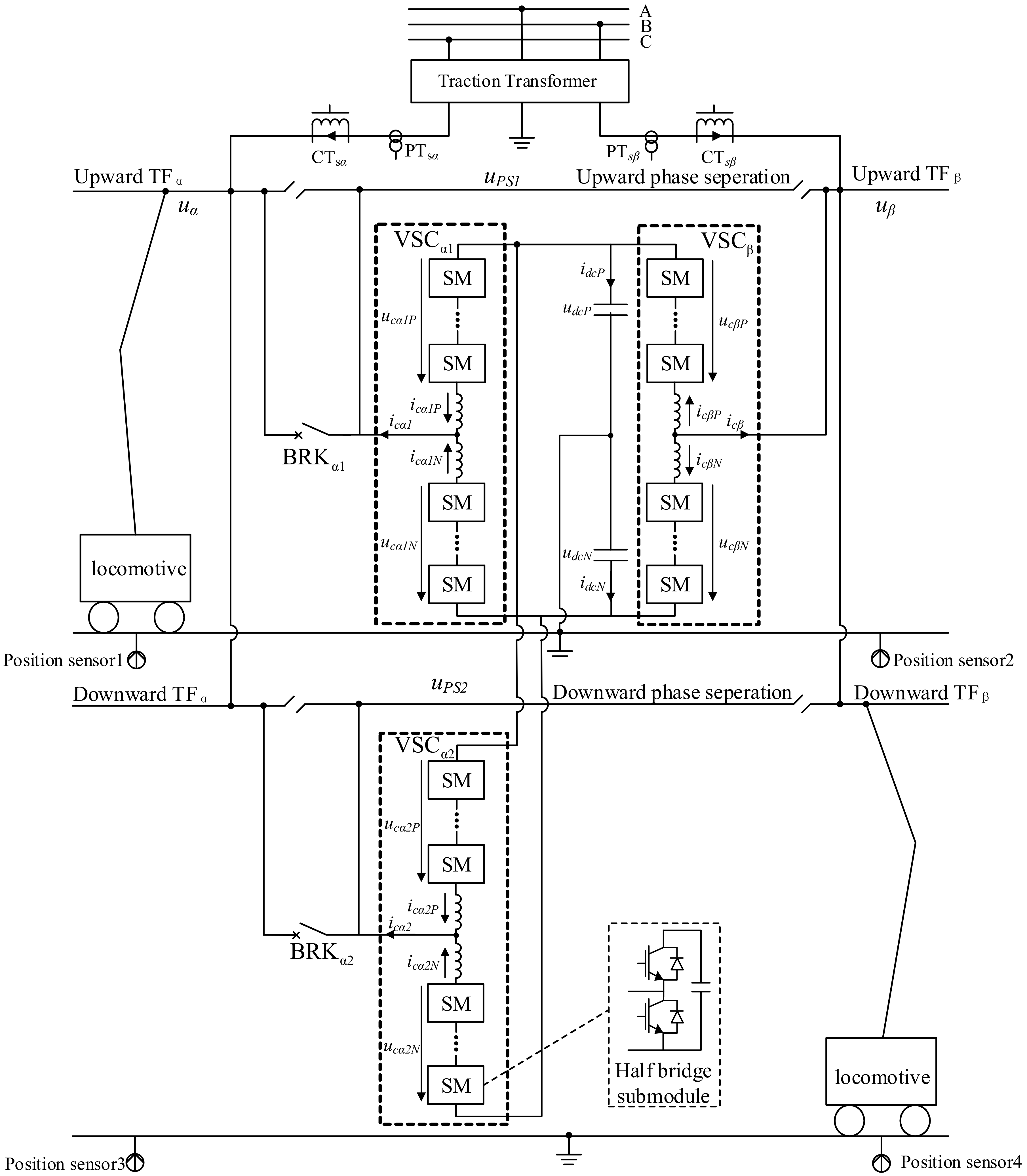
2. System Diagram of UPSP-PQC for Double-Track Electrified Railway

The traction transformer changes three-phase voltages of the public power grid to two single-phase voltages for the traction network. The phase difference between two single-phase voltages may be 60 or 90 degrees, depending on the wiring modes of the traction transformer. The four wiring modes of commonly used traction transformers are V/V wiring, YNd11 wiring, Scott wiring, and impedance matching balanced wiring. The voltage vector diagrams of primary and secondary windings for the four wiring modes are shown below. The voltage vectors of primary winding connected to public power systems are u A , u B and u C . The voltage vectors of secondary winding connected to traction feeders are u α , u β . The phase difference between u α and u β is 60 degrees for V/V wiring and YNd11 wiring. The phase difference between u α and u β is 90 degrees for Scott wiring and impedance matching balanced wiring. The wiring modes are shown in Figure 1.
The double-track traction power supply system and UPSP-PQC based on modular multilevel converter (MMC) are shown in Figure 2. SM denotes a half bridge sub-module. Each single-phase voltage is connected to α phase traction feeder (TFα) and β phase traction feeder (TFβ) of both upward and downward direction in the traction substation. There must be a PS between adjacent traction feeders on both directions due to the phase difference of the two voltages.
The UPSP-PQC scheme for double-track railway adopts a three-phase MMC converter topology. The three single-phase MMC converters   VSC α 1 , VSC α 2 and VSC β are connected back-to-back with common DC capacitors. Every single-phase MMC converter has a leg consisting of several series-connected half-bridge sub-modules. The AC output terminals of VSC α 1 and VSC α 2 are connected to PS and traction feeders through breakers. The intermediate points of two common DC capacitors are connected to the ground. The capacities of both VSC α 1 and VSC α 2 are equal to half of VSC β . Four position sensors are respectively located on the ground to provide the locomotive position information from both directions.

3. Working Modes and Principle Analysis of UPSP-PQC

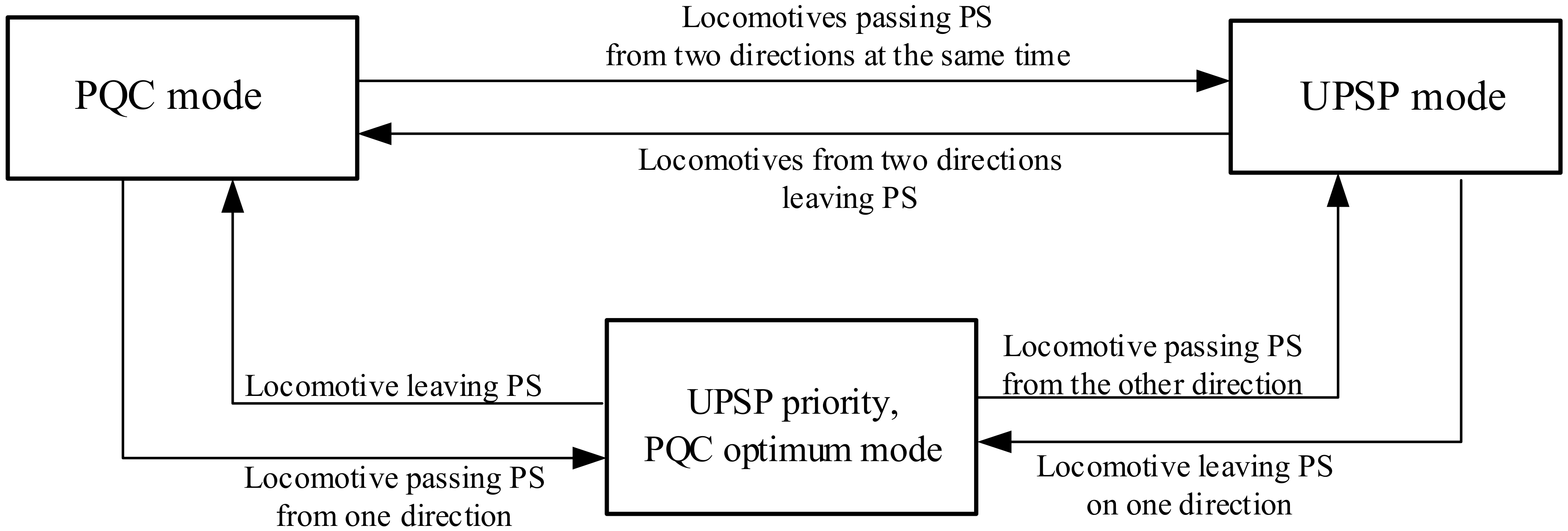
3.1. Analysis of Working Modes

There are three working modes of UPSP-PQC for double-track electrified railways, including uninterruptible power supply PS passing (UPSP) mode, power quality compensation (PQC) mode and UPSP priority, and PQC optimum mode.
(1)
UPSP mode: The UPSP-PQC scheme works in the UPSP mode when there are locomotives passing PS from both upward and downward direction at the same time. Under this mode, BRK α 1 and BRK α 2 are all disconnected. VSC β absorbs active power from TFβ. VSC α 1 and VSC α 2 transfer active power to upward and downward TFα and make locomotives pass PS without power loss according to the principle given in Section 3.2.
(2)
PQC mode: When there is no locomotive passing PS from either directions, UPSP-PQC works in PQC mode. BRK α 1 and BRK α 2 are both closed. The output power of VSC β is equal to the compensation power required by the β phase, but the output power of VSC α 1 and VSC α 2 is half the compensation power required by the α phase.
(3)
UPSP priority, PQC optimum mode: If there is a locomotive passing through PS from only one direction, UPSP-PQC scheme works in UPSP priority, PQC optimum mode. The circuit breaker on the direction of the locomotive passing through PS is disconnected, and the corresponding converter works in UPSP mode, providing power to the locomotive. The circuit breaker of the other direction is closed. The converter on this direction and VSC β works in the power quality compensation mode, and the output power is equal to the compensation power required by the α phase and β phase respectively. The switching conditions in three working modes of UPSP-PQC scheme are shown in Figure 3.

3.2. Working Principle of UPSP Mode

When a locomotive enters PS from either upward or downward direction, the corresponding position sensor will send a detection signal. The voltage of PS is regulated by converters to change from the voltage of the initial traction feeder to that of the destination traction feeder.
Take the electric locomotive moving from α phase to β phase i.e., upward direction, as an example. The frequency of traction feeder voltage is f 0 . The RMS values of two traction feeder voltages are U α and U β , and the phases are φ α and φ β , respectively. If the voltage frequency of the PS is f α β and the transition time is T Δ , the voltage phase of PS changes from TFα to TFβ. Then there is
T Δ × f 0 + φ β φ α = T Δ × f α β
So
f α β = f 0 + φ β φ α T Δ
At the same time, the RMS value of PS voltage changes from U α to U β . Therefore, from the beginning time t of the UPSP mode, the RMS value of the PS voltage can be expressed as
U p s α β = U α + U β U α T Δ t
During the process of UPSP mode, the instantaneous value of PS voltage is
u p s α β = 2 U p s α β s i n ( 2 π f α β + φ α )
Similarly, if the locomotive is from the β phase to the α phase, then the frequency, RMS value and instantaneous value of the electrical PS voltage can be expressed as
f β α = f 0 + φ α φ β T Δ
U p s β α = U β + U α U β T Δ t
u p s β α = 2 U p s β α s i n ( 2 π f β α + φ β )

3.3. Working Principle of PQC Mode

Under the PQC mode, the locomotive loads can be calculated with the voltage and current of the secondary winding of traction transformer, as shown in Figure 1. PTα and PTβ are the voltage hall that was used to measure voltages of the secondary winding of the traction transformer. CTα and CTβ are the current hall that is used to measure the current of secondary winding.
Assuming that the phase α and β phase traction power supply arm voltages are u α and   u β , the total load currents of the upward and downward are   i L α and i L β ; P L α , Q L α are the total active power and reactive power of the α phase load, and P L β , Q L β are the β phase load of total active power and reactive power, according to the instantaneous power theory of single-phase circuit
P L α = 1 2 u α i L α + u α i L α Q L α = 1 2 u α i L α u α i L α P L β = 1 2 u β i L β + u β i L β Q L β = 1 2 u β i L β u β i L β
In the formula, u α ,   u β ,   i L α ,   i L β are respectively obtained by delaying   u α , u β   ,   i L α , i L β by a quarter of the voltage period. The output power of the converter is expressed by the equations listed in Table 1 [23]. As can be seen in the table, the ultimate goal is to achieve load balancing from the view of the public power system. For active power, the unbalanced amount needed to be transferred between two traction feeders, which are half of ( P L α P L β ) . Since there are two converters in the α phase, P c α 1 and P c α 2   equal to half of P c β . For reactive power, compenstation values are different under different wiring methods. For Scott and impedance matching balance, only the reactive power of the locomotive load needs to be compensated. For V/V and YNd11, the influence of active power needs to be considered in the reactive power compensation process.
In Table 1, P c α 1 = P c α 2 and Q c α 1 = Q c α 2 are the active power and reactive power output of VSC α 1 and VSC α 2 , respectively. P c β and Q c β are the active power and reactive power output of VSC β , respectively. The compensation current can be deduced from the inverse transformation of single-phase instantaneous power theory as
i c α 1 P Q = 2 u α P c α 1 + 2 u α Q c α 1 u α 2 + u α 2 i c α 2 P Q = 2 u α P c α 2 + 2 u α Q c α 2 u α 2 + u α 2 i c β P Q = 2 u β P c β + 2 u β Q c β u β 2 + u β 2
where u α and u β are separately obtained through a delay of u α and u β by a quarter of voltage period.

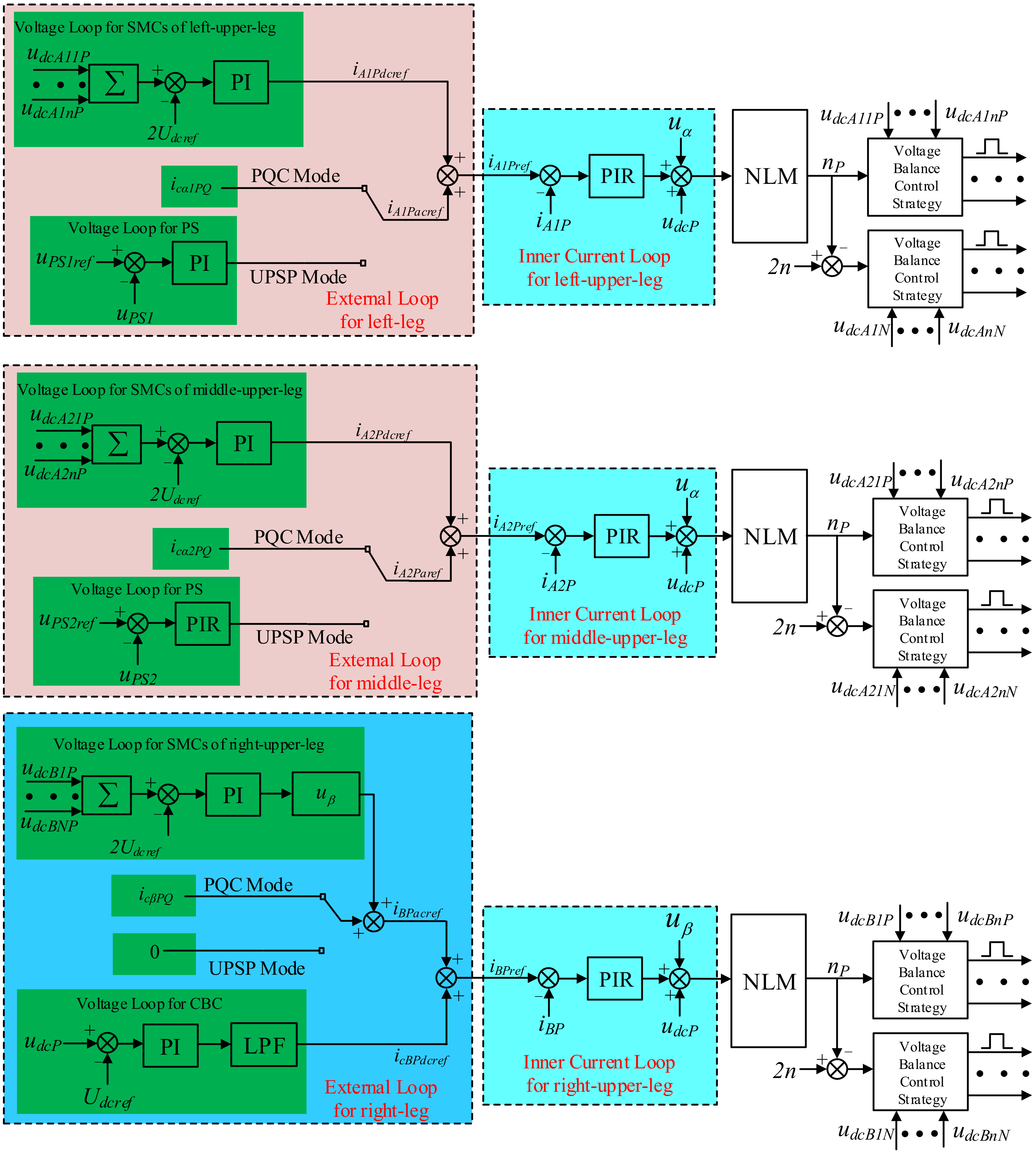
4. Control Strategy of Three-Leg MMC-Based UPSP-PQC Scheme

The control objectives of the UPSP-PQC based on the three-leg MMC structure include two aspects:
(I)
When it works in the UPSP mode, the right leg converter absorbs active power from TFβ by controlling the AC current and transfers power to the left leg and middle leg. The output voltage of the left-leg and middle-leg converter are regulated according to the principle given above during the phase-shifting process. When UPSP-PQC operates in the PQC mode, the currents in the left, middle and right legs correspond to Equation (2) to minimize the negative sequence current flowing into the PPS.
(II)
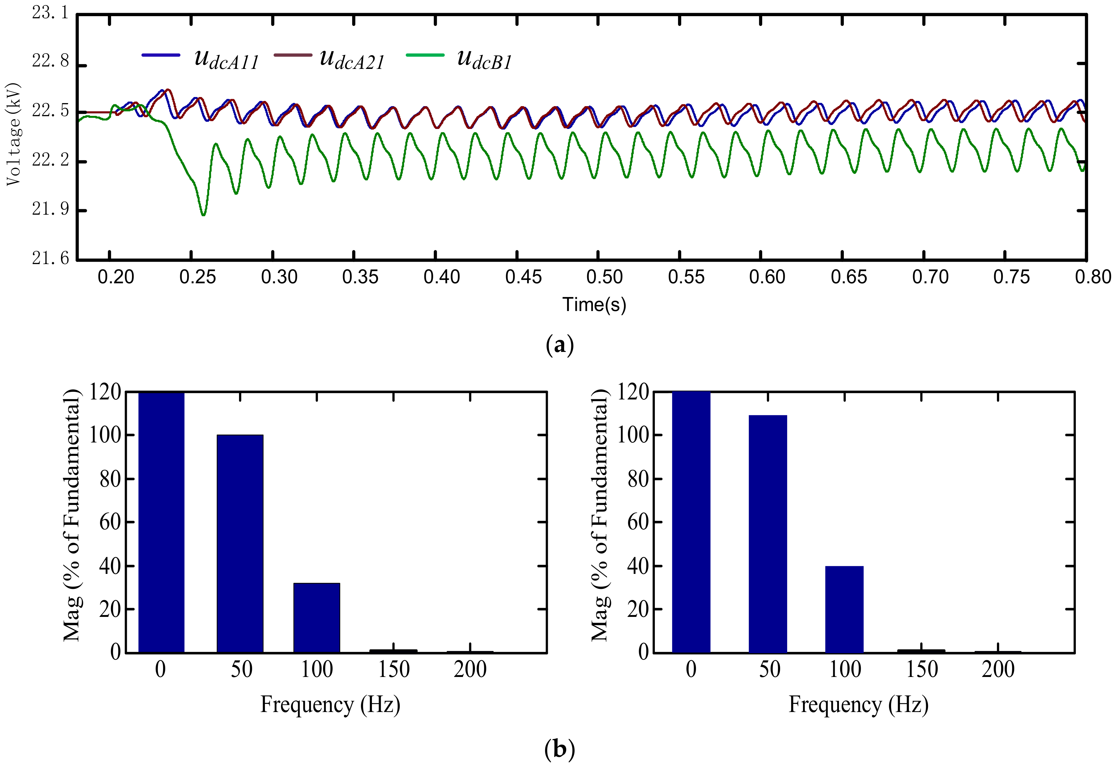
The DC voltages of the common bus capacitors remain stable, and the DC voltages of the sub-module capacitors (SMCs) are equal.
To realize the control object above, a double closed-loop control strategy is applied as illustrated in Figure 4. The control strategy of every leg consists of an external loop, internal loop and pulse generation. The specific functions and implementation of every control part are explained as follows:

4.1. External Control Loop

The external loop of each leg generates a reference current for the internal loop. As for the right leg, VSC β must absorb active power from TFβ to maintain the voltages of the SMCs. Hence, the AC current component can be obtained by multiplying the voltage of TFβ with the output of the PI controller, with its input being the difference between the sum of SMC voltages and its reference, as shown in Equation (10). To maintain voltages of the common bus capacitors, u d c P and u d c N , as reference values, the right leg must transfer power to the common DC capacitors. Therefore, the DC current component corresponds to the output of the PI controller, with its input being the difference between the voltage of the common bus capacitors and its reference value. In addition, a low-pass filter is used to minimize the AC component of the PI controller output. Then, when UPSP-PQC operates in PQC mode or UPSP priority, PQC optimum mode, the compensation current in Equation (2) should be included in the reference current.
i B P a c r e f = u β K p i = 1 N u d c B i P 2 U d c r e f + K i i = 1 N u d c B i P 2 U d c r e f
The DC current component is the output of PI controller in the left-leg converter, with its input being the difference between the voltage of the SMC and the reference value. When the device operates in the PQC mode, the output current of the left-leg converter should contain i c α P Q in Equation (2).
When UPSP-PQC operates in UPSP mode, it must regulate the voltage of PS to track the reference value. Thus, the AC component of the left converter corresponds to the output of the PI controller. The output of voltage loop for PS is derived by proportional-integral-resonance (PIR) controller, with its input being the difference between the voltage of PS and the reference value. The current reference generated by voltage Loop for PS is the fundamental AC current that should be supplied to the locomotive by the converter.

4.2. Internal Control Loop

The internal loop of each upper leg generates a reference voltage for pulse generation. Hence, every leg has a proportional-integral-resonance (PIR) controller, with their input being the differences between the reference and measured current. The most commonly used pulse generation scheme for the MMC topology is the nearest level modulation (NLM) [24] and the gate control signals are generated for the IGBTs in all sub-modules [25,26].

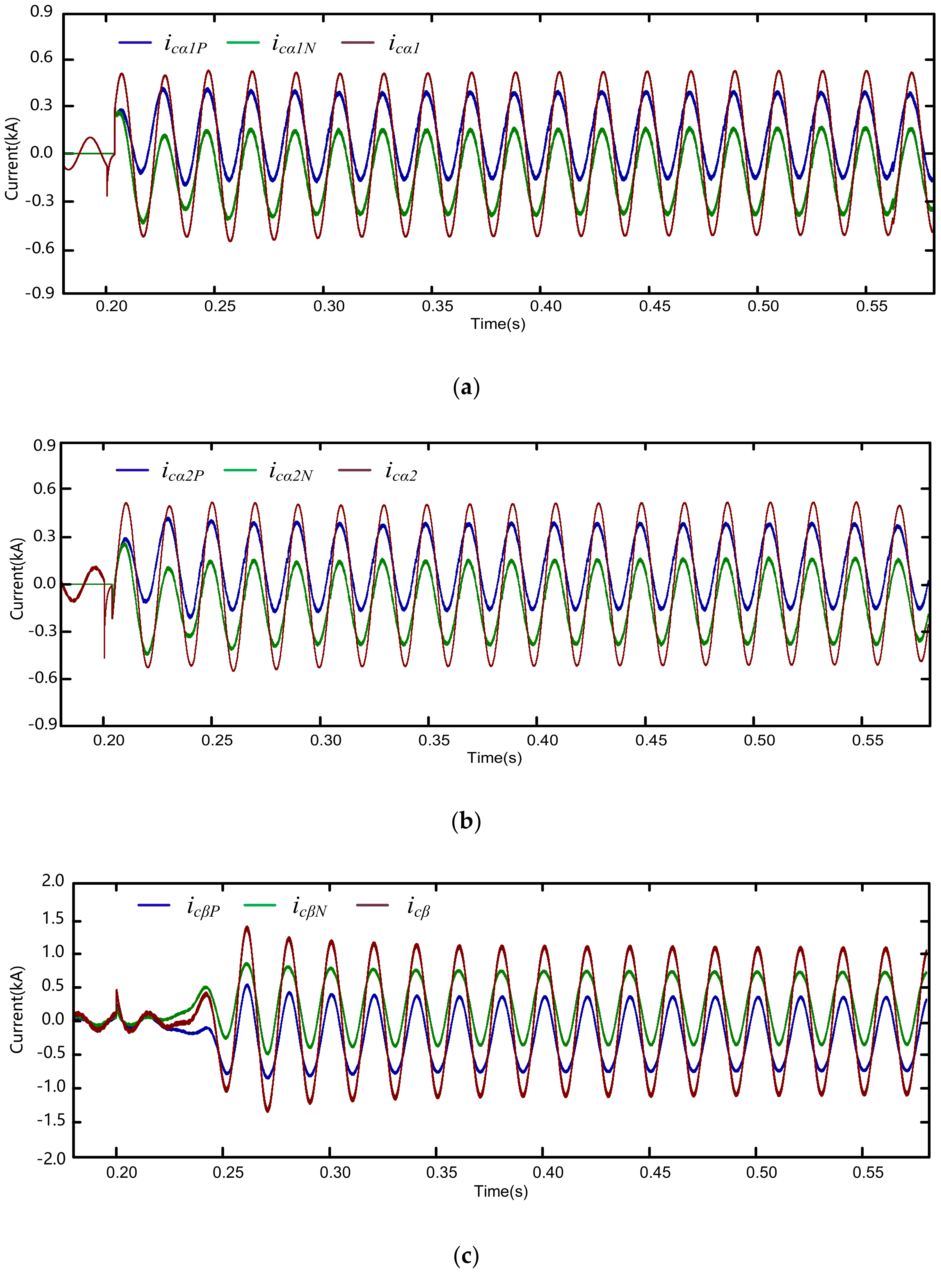
5. Simulation Verification

In order to verify the correctness of the proposed topology and working mode of UPSP-PQC scheme, a simulation model in PSCAD/EMTDC is established. The voltages of PPS and traction networks are 110 kV and 27.5 kV, respectively. The traction transformer uses V/V wiring. The upper and lower arms of every leg in the converters are composed of four sub-modules. The capacity of the locomotive is 10 MW. The parameters in the simulation model of UPSP-PQC scheme are listed in the following Table 2.

5.1. Simulation Result of UPSP Mode

In this simulation, UPSP-PQC is set to start working at 0.2 s, and at the same time, two locomotives are designed to enter PS from two directions. The simulation results are shown from Figure 5, Figure 6 and Figure 7. Figure 5 illustrates the voltage waveforms of two traction feeders and PS in upward and downward direction. Figure 5a illustrates the voltage waveforms of two traction feeders and upward PS. Before 0.2s, there is no locomotives passing PS, so BRK α 1 is closed and the voltage of upward PS is u α . When a locomotive enters PS at 0.2 s from upward direction, BRK α 1 opens and VSC α 1 begins to regulate the voltage of upward PS to make it still equal to u α . The total time power supply dead zone is no more than 5 ms. Then, 60 ms later, the voltage of upward PS starts to change from u α to u β smoothly. In order to better show the phase-shifting process, the duration of phase-shifting process is set to 0.3 s, which is much shorter and more practical. The voltage frequency of upward PS during the phase-shifting process is 49.44 Hz. Figure 5b illustrates the voltage waveforms of two traction feeders and downward PS. Similar to Figure 5a, the voltage of downward PS gradually varies from u β to u α .
Figure 6 shows the current waveforms of three legs in converters during the phase-shifting process. Figure 6a shows the upper leg current i c α 1 P , lower leg current i c α 1 N and ac output current i c α 1 of VSC α 1 . Before 0.2 s, the output current is zero and after a locomotive enters PS at 0.2 s, VSC α 1 begins to provide power to the locomotive. The RMS value of i c α 1 is 0.364 kA, which is equal to the power of the locomotive (10 MW) divided by traction feeder voltage (27.5 kV). The upper and lower leg current contain ac and dc components. The AC component is half of the ac output current. DC component is 0.111 kA, which equals to the power transmitted through VSC α 1 divided by the total voltage of common dc capacitors (90 kV). Figure 6b shows the current waveforms of the upper leg current, lower leg current and ac output current of VSC α 2 . The difference between Figure 6b and Figure 6a is the phase variation direction of the current. Figure 6c shows the current waveforms of the upper leg current, lower leg current and ac output current of VSC β . After VSC α 1 and VSC α 2 begin to supply power to two locomotives at 0.2 s, VSC β starts to absorb active power from TFβ. The RMS value of i c β is 0.727 kA, which is twice of i c α 1 . The AC component of i c β P is 0.364 kA and dc component is 0.222 kA.
Figure 7a shows the voltages of one sub-module capacitor in VSC α 1 ,   VSC α 2 and VSC β . It can be seen that during the phase-shifting process, capacitor voltages remain stable and tend to track the reference value (22.5 kV). The spectrum of capacitor voltages is shown in Figure 7b. The capacitor voltages contains a dc component and 50 Hz and 100 Hz components. The phase of ac components gradually changes with that of the current during the phase-shifting process. The ac components in u d c A 11 and u d c A 21 are almost reverse phase to that of u d c B due to an opposite active power flow direction in VSC α 1 ,   VSC α 2 and VSC β . Figure 8 shows the voltage of sub-module capacitors, which keep balancing during the phase-shifting process. Figure 9 shows that the voltages of common DC capacitors are stable during the simulation.

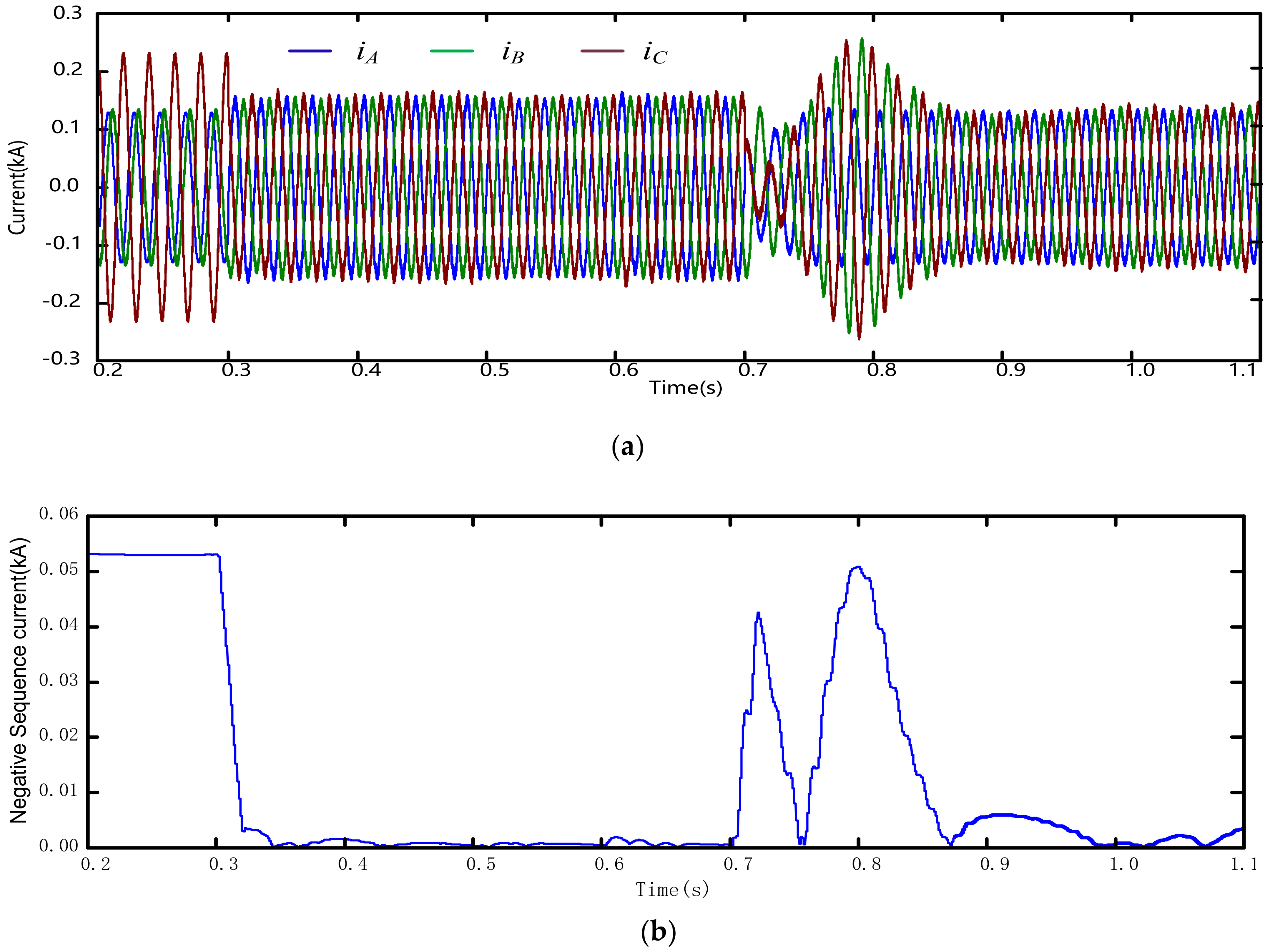
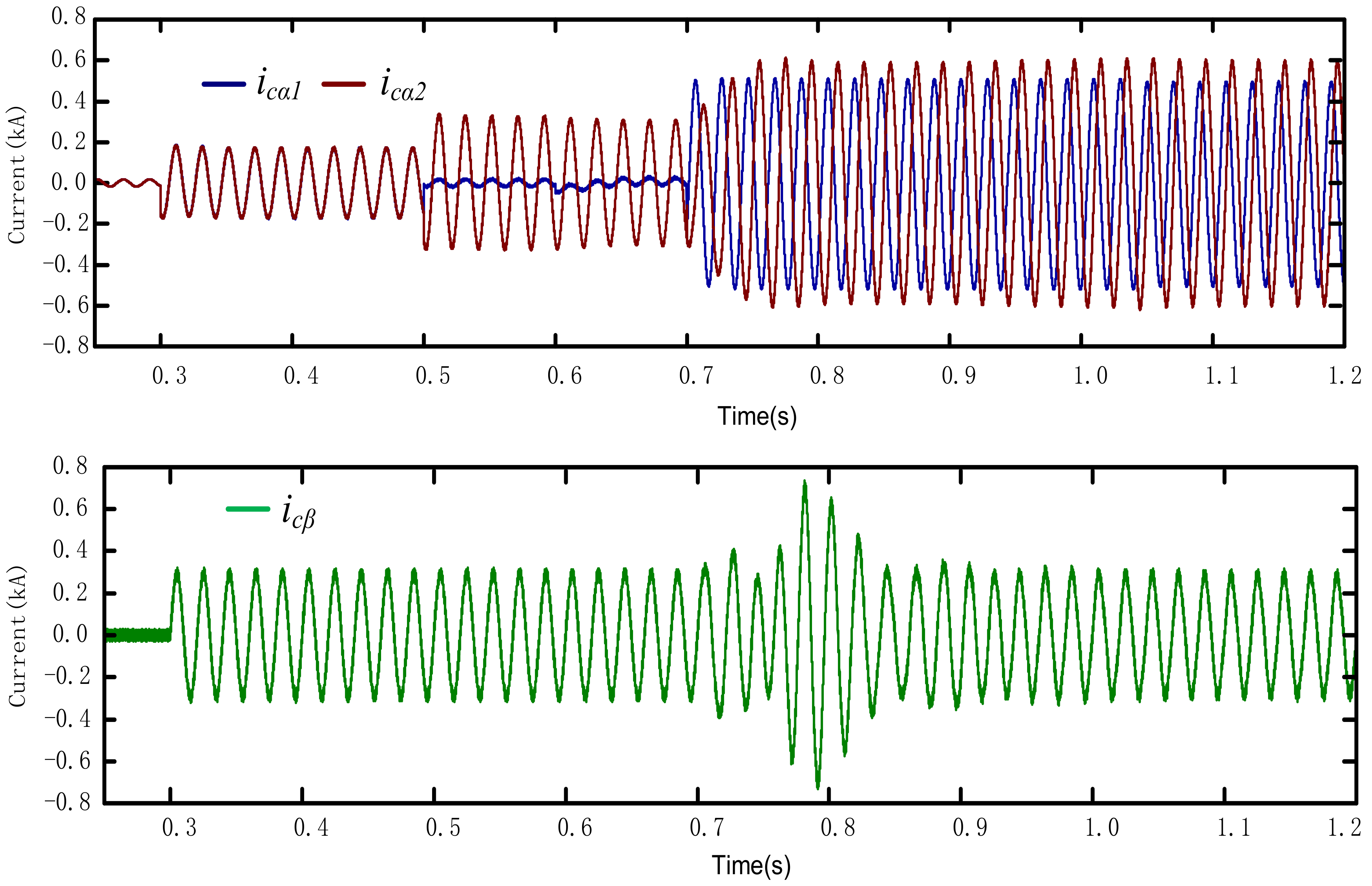
5.2. Simulation Result for UPSP Priority, PQC Optimum Mode

UPSP-PQC is set to start working in PQC mode at 0.3 s. At 0.5 s, location sensors detect a locomotive that will enter PS from upward TFα and VSC α 1 , which stops compensating power quality. At 0.7 s, the locomotive enters PS. There is always a locomotive connected to downward TFβ during the whole simulation process.
Figure 10 illustrates the three-phase current from PPS and the negative sequence current. Figure 11 illustrates the output current of VSC α 1 ,   VSC α 2 and VSC β . Figure 12 illustrates the voltages of upward PS and traction feeders during the phase-shifting process. Before 0.3 s, UPSP-PQC does not work and the output current of VSC α 1 ,   VSC α 2 and VSC β are zero. The power needed by locomotives is transferred directly from PPS to traction feeders through traction transformers. The three-phase current is asymmetric and the negative sequence current is 0.053 kA. From 0.5 s, UPSP-PQC begins to operate in UPSP priority, PQC optimum mode. VSC α 1 is ready to supply power to the locomotive in upward direction and the output current reduces to zero. All of the α phase compensation currents are provided by VSC α 2 , and the output current of VSC α 2 becomes twice that before 0.5 s. At 0.7 s, locomotive enters PS, and VSC α 1 starts to supply power to the locomotive. In this period, the three-phase current from PPS still tends to be symmetrical. VSC α 1 starts to provide power for the locomotive. If active power is transferred from TFβ, the active power of the two locomotives are supplied by TFβ. Under this situation, the load unbalance of two traction feeders and negative sequence current penetration into PPS will be maximum. In order to retain the load balance of two traction feeders, the active power needed by the locomotive entering PS should be transferred from TFα through VSC α 2 . Only in this way can the active power balance of the two traction feeders be guaranteed and the negative sequence current flowing into PPS be minimized. Figure 12 shows that after the locomotive enters PS, the voltages of upward PS gradually change from u α to u β . This simulation clearly shows the UPSP priority, PQC optimum mode of UPSP-PQC scheme.

6. Conclusions

This paper proposes a novel uninterruptible power supply PS passing and power quality compensation scheme for double-track electrified railway, and three working modes are designed. Three-leg MMC topology-based UPSP-PQC schemes are given, which can realize the energy transfer between the upward and downward traction feeders. The control strategies of each converter under different working modes are analyzed, and the control effects under the typical working case modes have been simulated. Simulation results show that the proposed UPSP-PQC scheme can ensure that the locomotives passes PS without power-off or speed-loss, and the power quality of the whole traction substation is optimized at the same time. The power supply dead zone when the locomotive passing phase separation is reduced to no more than 5 ms and the negative sequence current decreases to zero after compensation.
Future work will require an analysis of the influence by uncertainty of traction load and parameters on the capacity design and control effect of UPSP-PQC scheme. An energy storage system, e.g., super capacitors and batteries, will be added to the UPSP-PQC and coordinated control between converters and energy storage systems will be studied.

Author Contributions

X.T. conceived and designed the study; X.L. and Z.Z. performed the simulations and experiments; X.T. and X.L. wrote the paper. All authors have read and agreed to the published version of the manuscript.

Funding

This research was funded by National Natural Science Foundation of China grant number 51707194 and National Key R&D Program of China under grant number 2017YFB1200800.

Conflicts of Interest

The authors declare no conflict of interest.

Nomenclature

SymbolUnitDefinition
f 0 HzFrequency of α , β phase traction feeder voltages
f α β , f β α HzFrequencies of phase separation voltages
φ α , φ β radPhases of α , β phase traction feeder voltages
u α , u β kVInstantaneous value of α , β phase traction feeder voltage
u α , u β kVdelay of u α and u β by a quarter of voltage period
u P S kVInstantaneous value of the phase-separation voltage
U p s α β , u p s β α kVInstantaneous value reference of the phase-separation voltage
T Δ sTransition time of phase shifting
i c α 1 , i c α 2 , i c β kAOutput current of VSC α 1 , VSC α 2 and VSC β
i c α 1 P Q , i c α 2 P Q , i c β P Q kACompensation current reference under power compensation mode
u d c P , u d c N kVVoltages of common DC capacitors
u d c A 11 , u d c A 21 , u d c B 1 kVVoltages of one sub-module capacitor in VSC α 1 , VSC α 2 , VSC β
P L α ,   P L β MWTotal active power of the locomotive powered by TFα, TFβ
Q L α , Q L β MVarTotal reactive power of the locomotive powered by TFα, TFβ
P c α 1 , P c α 2 , P c β MWActive power output of VSC α 1 , VSC α 2 , VSC β
Q c α 1 , Q c α 2 , Q c β MVarReactive power output of VSC α 1 , VSC α 2 , VSC β

References

  1. Lucca, G. Influence of railway line characteristics in inductive interference on railway track circuits. IET Sci. Meas. Technol. 2019, 13, 9–16. [Google Scholar]
  2. Madane, S.; Deokar, S.A. Harmonic mitigation in traction supply system by using half bridge converter. In Proceedings of the 2017 International Conference on Data Management, Analytics and Innovation (ICDMAI), Pune, India, 24–26 February 2017; pp. 161–165. [Google Scholar]
  3. Kandaev, V.A.; Avdeeva, K.V.; Utkina, A.V. Determination of Electrical Quantities in the Traction Rail Network and Buried Pipelines Located Under the Influence of Stray Currents from Electrified Railway Transport. In Proceedings of the 2018 Dynamics of Systems, Mechanisms and Machines (Dynamics), Omsk, Russia, 13–15 November 2018; pp. 1–8. [Google Scholar]
  4. Kong, W.; Ma, K.; Wu, Q. Three-Phase Power Imbalance Decomposition into Systematic Imbalance and Random Imbalance. IEEE Trans. Power Syst. 2018, 33, 3001–3012. [Google Scholar]
  5. Ma, F.; Xu, Q.; He, Z.; Tu, C.; Shuai, Z.; Luo, A.; Li, Y.; Ma, F.; Shuai, Z. A Railway Traction Power Conditioner Using Modular Multilevel Converter and Its Control Strategy for High-Speed Railway System. IEEE Trans. Transp. Electrif. 2016, 2, 96–109. [Google Scholar]
  6. Yeh, C.; Manjrekar, M.D. A Reconfigurable Uninterruptible Power Supply System for Multiple Power Quality Applications. IEEE Trans. Power Electron. 2007, 22, 1361–1372. [Google Scholar]
  7. Liu, M.; Lu, Y.; Wei, H.; Zhu, X.; Kong, Z.; Zhao, L.; Zhao, S.; Bai, M. Experimental Research on Articulated Electric Phase Separation Overvoltage. Electrified Railw. 2007, 14, 15–17. [Google Scholar]
  8. Lao, K.-W.; Wong, M.-C.; Dai, N.Y.; Wong, C.-K.; Lam, C.-S. Analysis of DC-Link Operation Voltage of a Hybrid Railway Power Quality Conditioner and Its PQ Compensation Capability in High-Speed Cophase Traction Power Supply. IEEE Trans. Power Electron. 2016, 31, 1643–1656. [Google Scholar]
  9. Long, Y.; Xiao, X.; Xu, Y.; Baolai, Y.; Xu, Y.; Hao, J. MMC-UPQC: Application of Modular Multilevel Converter on Unified Power Quality Conditioner. In Proceedings of the 2013 IEEE Power & Energy Society General Meeting, Vancouver, BC, Canada, 21–25 July 2013; pp. 1–5. [Google Scholar]
  10. Fu, G.; Qiu, L.; Hu, J. Research on Flexible Ground Automatic Neutral-Section Passing Technology Base on Voltage Compensation. In Proceedings of the 2019 IEEE Vehicle Power and Propulsion Conference (VPPC), Hanoi, Vietnam, 14–17 October 2019; pp. 1–7. [Google Scholar]
  11. Hu, H.; He, Z.; Li, X.; Wang, K.; Gao, S. Power-Quality Impact Assessment for High-Speed Railway Associated With High-Speed Trains Using Train Timetable—Part I: Methodology and Modeling. IEEE Trans. Power Deliv. 2015, 31, 693–703. [Google Scholar]
  12. Wang, Q.; Lu, J.; Wang, Q.; Duan, J. Transient overvoltage study of auto-passing neutral section in high-speed railway. In Proceedings of the 2017 IEEE Transportation Electrification Conference and Expo, Asia-Pacific (ITEC Asia-Pacific), Harbin, China, 7–10 August 2017; pp. 1–5. [Google Scholar]
  13. Liu, Z.; Hu, X.; Liao, Y. Vehicle-Grid System Stability Analysis Based on Norm Criterion and Suppression of Low-Frequency Oscillation with MMC-STATCOM. IEEE Trans. Transp. Electrif. 2018, 4, 757–766. [Google Scholar]
  14. Rodrigues, P.; Morais, V.A.; Martins, A.; Carvalho, A. STATCOM Simulation Models for Analysis of Electrified Railways. In Proceedings of the IECON 2019—45th Annual Conference of the IEEE Industrial Electronics Society, Lisbon, Portugal, 14–17 October 2019; pp. 2257–2262. [Google Scholar]
  15. Chen, M.; Chen, Y.; Wei, M. Modeling and Control of a Novel Hybrid Power Quality Compensation System for 25-kV Electrified Railway. Energies 2019, 12, 3303. [Google Scholar]
  16. Ma, Q.; Guo, X.; Luo, P.; Zhang, Z. Coordinated Control Strategy Design of New Railway Power Conditioner Based on Super Capacitor Energy Storage. Trans. China Electrotech. Soc. 2019, 34, 765–776. [Google Scholar]
  17. Ma, Q.; Tan, L.; Luo, P. Negative sequence optimization compensation strategy for hybrid power quality control system of V/v traction power supply station. Electr. Power Autom. Equip. 2017, 37, 128–132. [Google Scholar]
  18. Luo, P.; Li, Q.; Ma, Q. Multi-scenario Capacity Optimization Design of Railway Power Conditioner Considering Load Uncertainty. In Proceedings of the IECON 2019—45th Annual Conference of the IEEE Industrial Electronics Society, Lisbon, Portugal, 14–17 October 2019; pp. 2714–2719. [Google Scholar]
  19. Park, S.; Salkuti, S.R. Optimal Energy Management of Railroad Electrical Systems with Renewable Energy and Energy Storage Systems. Sustainability 2019, 11, 6293. [Google Scholar]
  20. Hosseini, S.M.; Carli, R.; Dotoli, M. Robust Day-Ahead Energy Scheduling of a Smart Residential User Under Uncertainty. In Proceedings of the 2019 18th European Control Conference (ECC), Naples, Italy, 25–28 June 2019; pp. 935–940. [Google Scholar]
  21. Carli, R.; Dotoli, M. Decentralized control for residential energy management of a smart users’ microgrid with renewable energy exchange. IEEE CAA J. Autom. Sin. 2019, 6, 641–656. [Google Scholar]
  22. Geidl, M.; Koeppel, G.; Favre-Perrod, P.; Klockl, B.; Andersson, G.; Frohlich, K. Energy hubs for the future. IEEE Power Energy Mag. 2007, 5, 24–30. [Google Scholar]
  23. Dai, N.; Wong, C.; Wong, M.; Lao, K. Hybrid power quality conditioner for co-phase power supply system in electrified railway. IET Power Electron. 2012, 5, 1084–1094. [Google Scholar]
  24. Ricco, M.; Mathe, L.; Monmasson, E.; Teodorescu, R. FPGA-Based Implementation of MMC Control Based on Sorting Networks. Energies 2018, 11, 2394. [Google Scholar]
  25. Moranchel, M.; Huerta, F.; Sanz, I.; Bueno, E.; Rodríguez, F. A Comparison of Modulation Techniques for Modular Multilevel Converters. Energies 2016, 9, 1091. [Google Scholar]
  26. Zhou, F.; Luo, A.; Li, Y.; Xu, Q.; He, Z.; Guerrero, J.M. Double-Carrier Phase-Disposition Pulse Width Modulation Method for Modular Multilevel Converters. Energies 2017, 10, 581. [Google Scholar]
Figure 1. The four wiring modes: (a) V/V wiring; (b) YNd11 wiring; (c) Scott wiring; (d) Impedance matching balanced wiring.
Energies 13 00738 g001
Figure 2. System schematics of double-track traction power supply system and UPSP-PQC scheme based on Modular Multilevel Converter.
Energies 13 00738 g002
Figure 3. Working modes transition diagram of UPSP-PQC scheme.
Energies 13 00738 g003
Figure 4. Control strategy of three-leg MMC-based UPSP-PQC.
Energies 13 00738 g004
Figure 5. Voltage waveforms of traction feeders and PS in UPSP mode: (a) upward PS; (b) downward PS.
Energies 13 00738 g005
Figure 6. Upper leg current, lower leg current and output current in UPSP mode: (a) upper leg current; (b) lower leg current; (c) output current.
Energies 13 00738 g006
Figure 7. Capacitor voltage waveforms in UPSP mode: (a) Voltages of one sub-module capacitor in VSC α 1 ,   VSC α 2 and VSC β ; (b) Spectrum of sub-module capacitor voltages in Figure 6a.
Energies 13 00738 g007
Figure 8. Voltages of sub-module capacitors: (a) VSC α 1 ; (b) VSC α 2 ; (c) VSC β .
Energies 13 00738 g008
Figure 9. Voltages of common DC capacitors.
Energies 13 00738 g009
Figure 10. Three-phase current and negative sequence current of PPS in PQC mode and UPSP priority, PQC optimum mode: (a) Three phase current from PPS; (b) Negative sequence current into PPS.
Energies 13 00738 g010
Figure 11. Output current waveforms of VSC α 1 , VSC α 2 and VSC β .
Energies 13 00738 g011
Figure 12. Voltages of upward PS and traction feeders during phase shift process.
Energies 13 00738 g012
Table 1. Compensated power for different connections of traction transformer.
V/V and YNd11Scott and Impedance Matching Balance
P c α 1 P c α 2 P c β Q c α 1 Q c α 2 Q c β = 1 4 P L α P L β 1 4 P L α P L β 1 2 P L α P L β 3 12 P L α + P L β + Q L α 2 3 12 P L α + P L β + Q L α 2 3 6 P L α + P L β + Q L β P c α 1 P c α 2 P c β Q c α 1 Q c α 2 Q c β = 1 4 P L α P L β 1 4 P L α P L β 1 2 P L α P L β Q L α 2 Q L α 2 Q L β
Table 2. Parameters in simulation model.
SymbolDescriptionValue
U α ,   U β RMS voltage of TF27.5 kV
f PPS Voltage frequency of PPS50 Hz
NNumber of SMs in each arm4
U dcP , U dcN Voltage of common DC capacitor22.5 kV
C SM SM capacitance 5000   μ F
L 0 Arm inductance18 mH
f con Control frequency (selecting and sorting)10 kHz
f car Carrier frequency10 kHz

