Nanofluid Based on Carbon Dots Functionalized with Ionic Liquids for Energy Applications

 , and
, and 
Abstract
1. Introduction
2. Materials and Methods
2.1. Materials
2.2. Methods
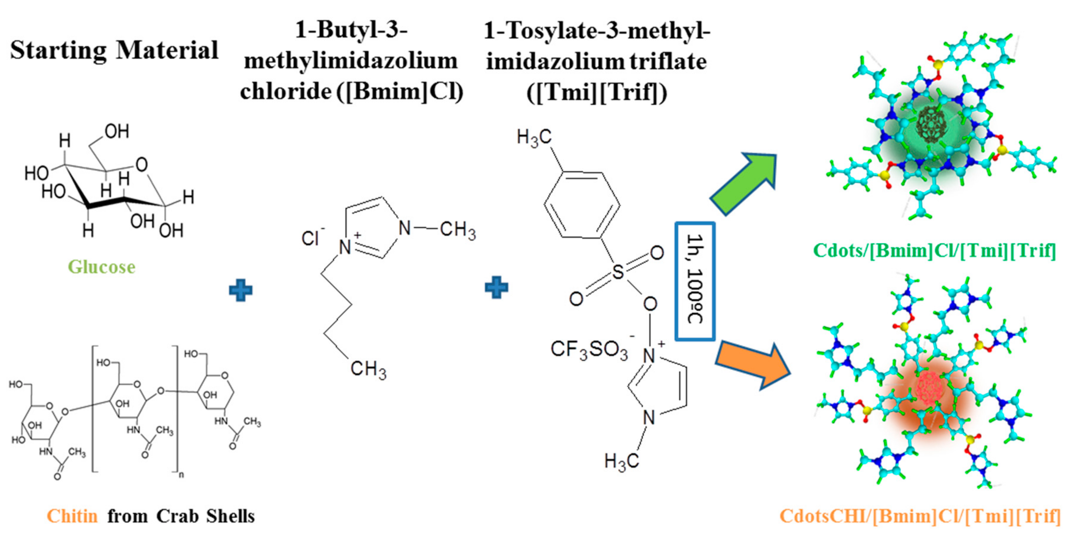
2.2.1. 1-Tosylate-3-Methyl-Imidazolium Triflate ([Tmi][Trif])
2.2.2. Nanofluid Synthesis
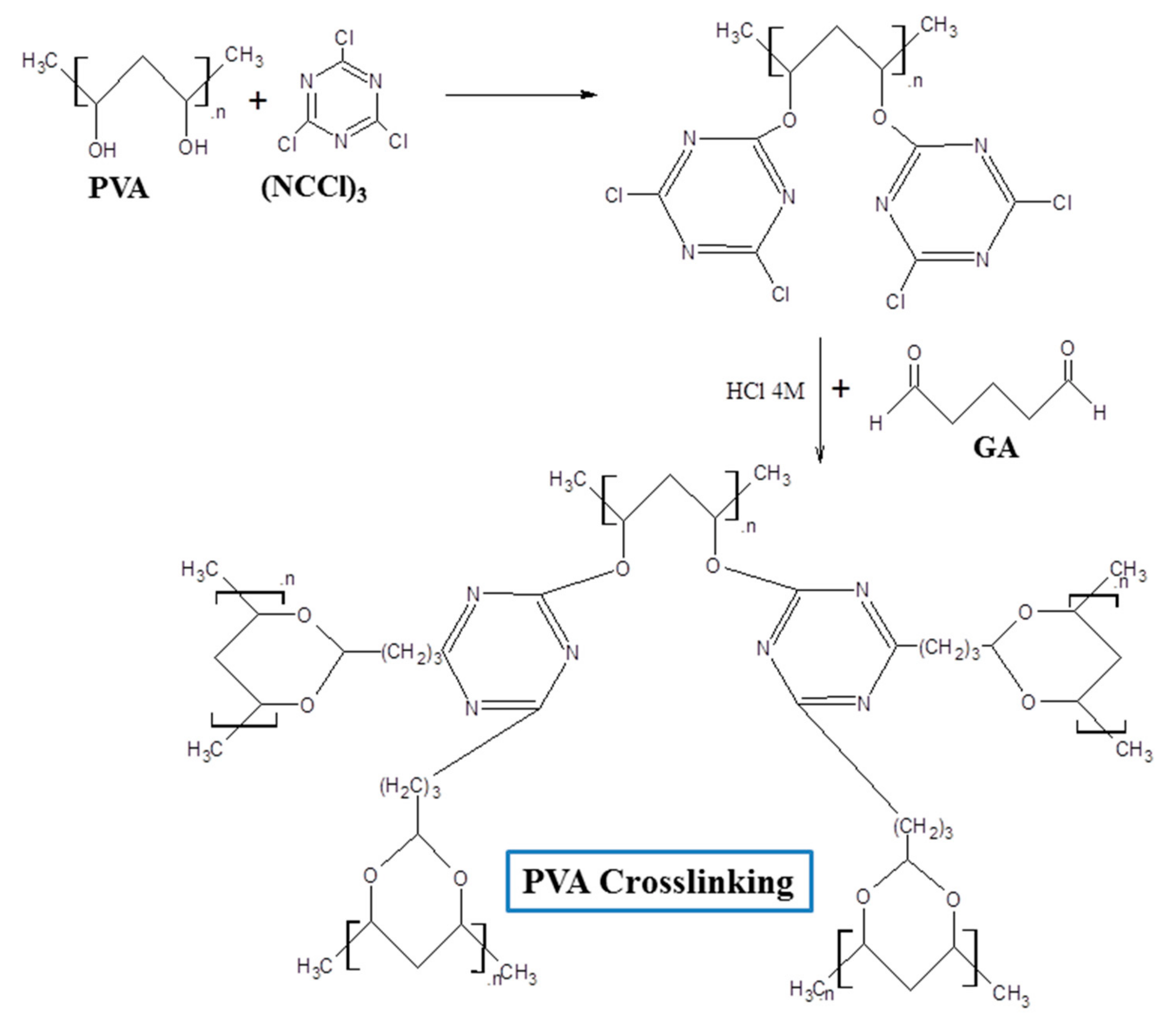
2.2.3. Preparation of the PVA/Nanofluid Membranes
2.3. Characterization
3. Results
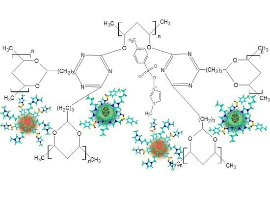
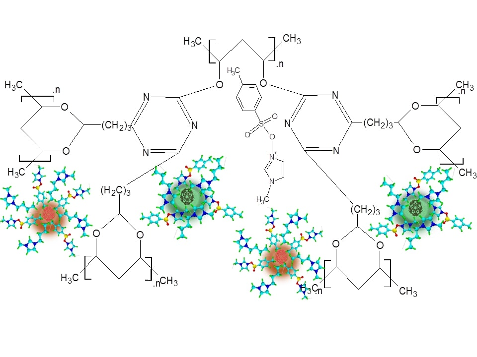
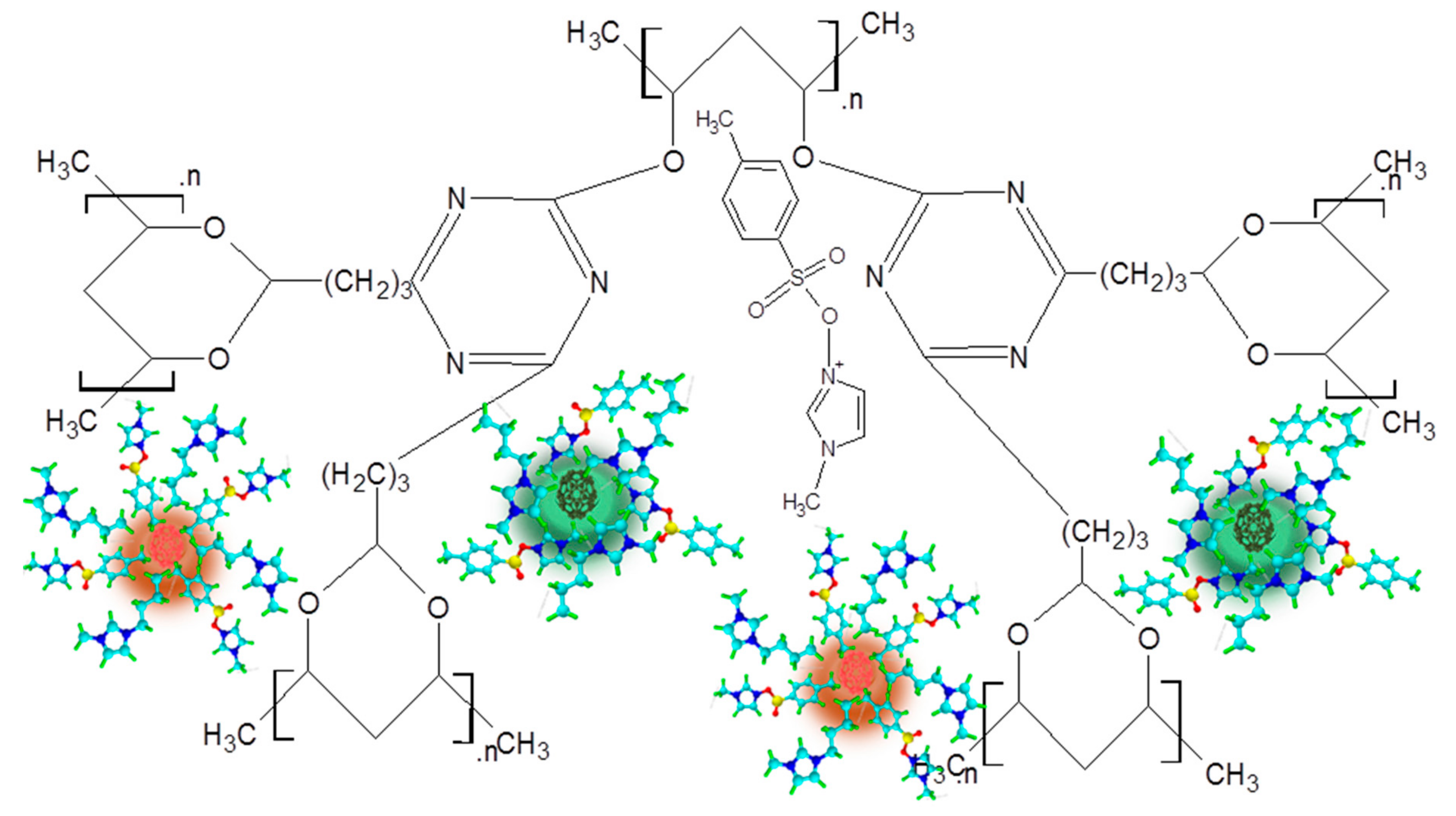
3.1. Fundamentals
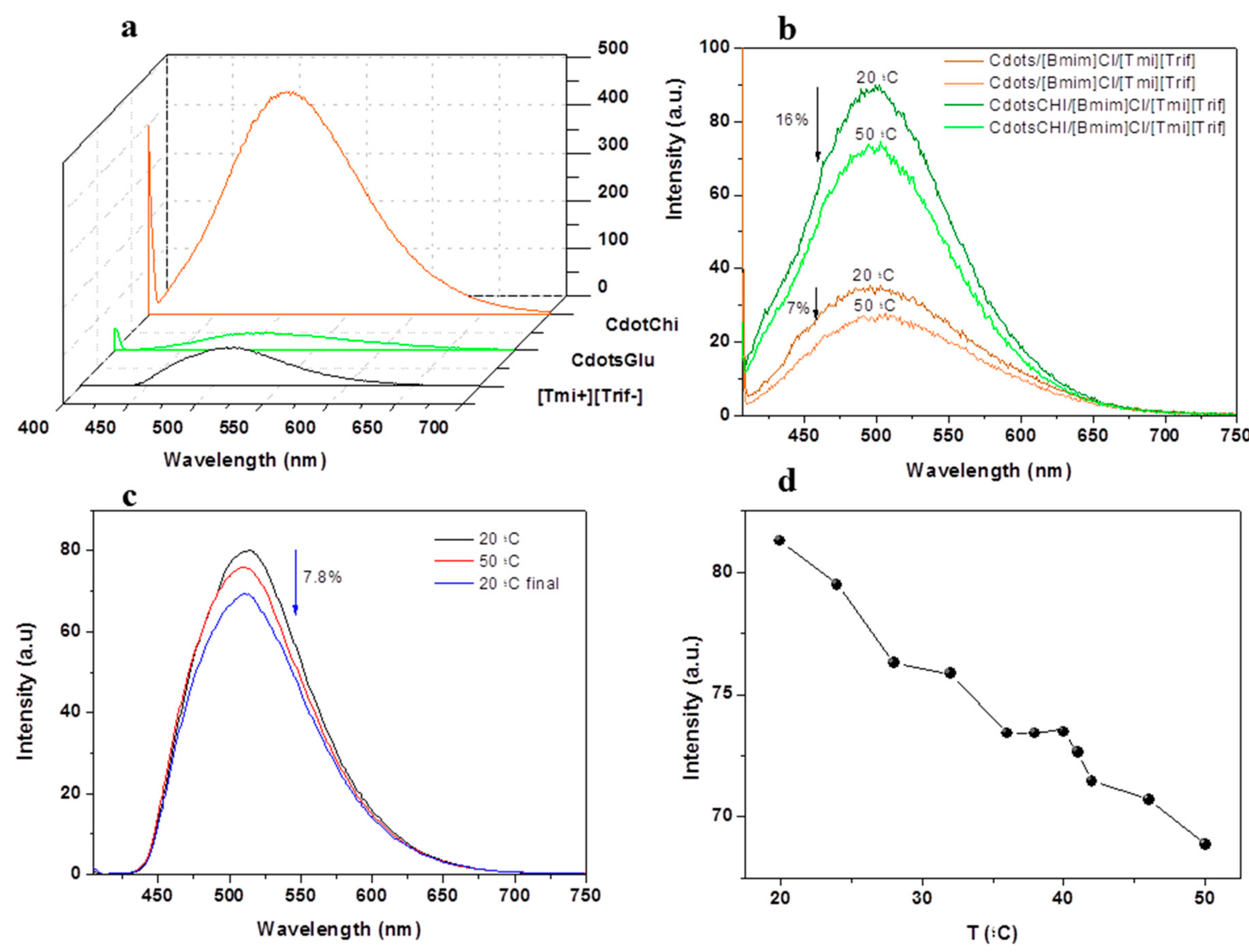
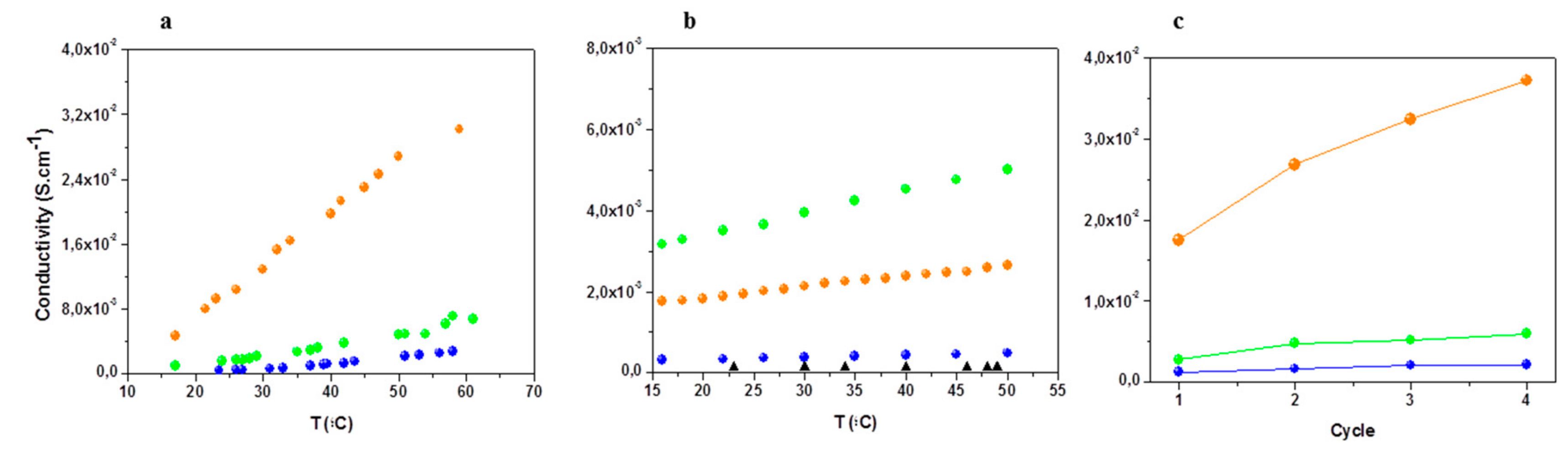
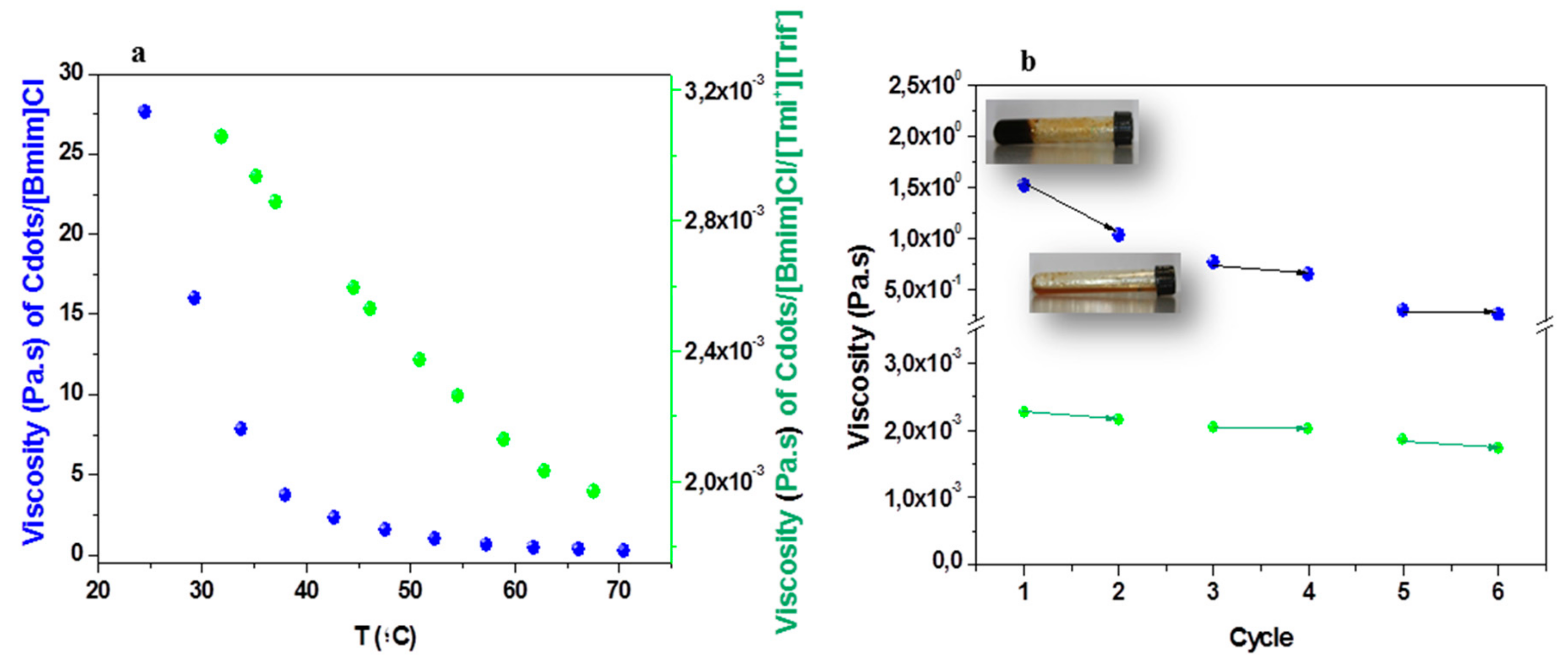
Nanofluid Characterization
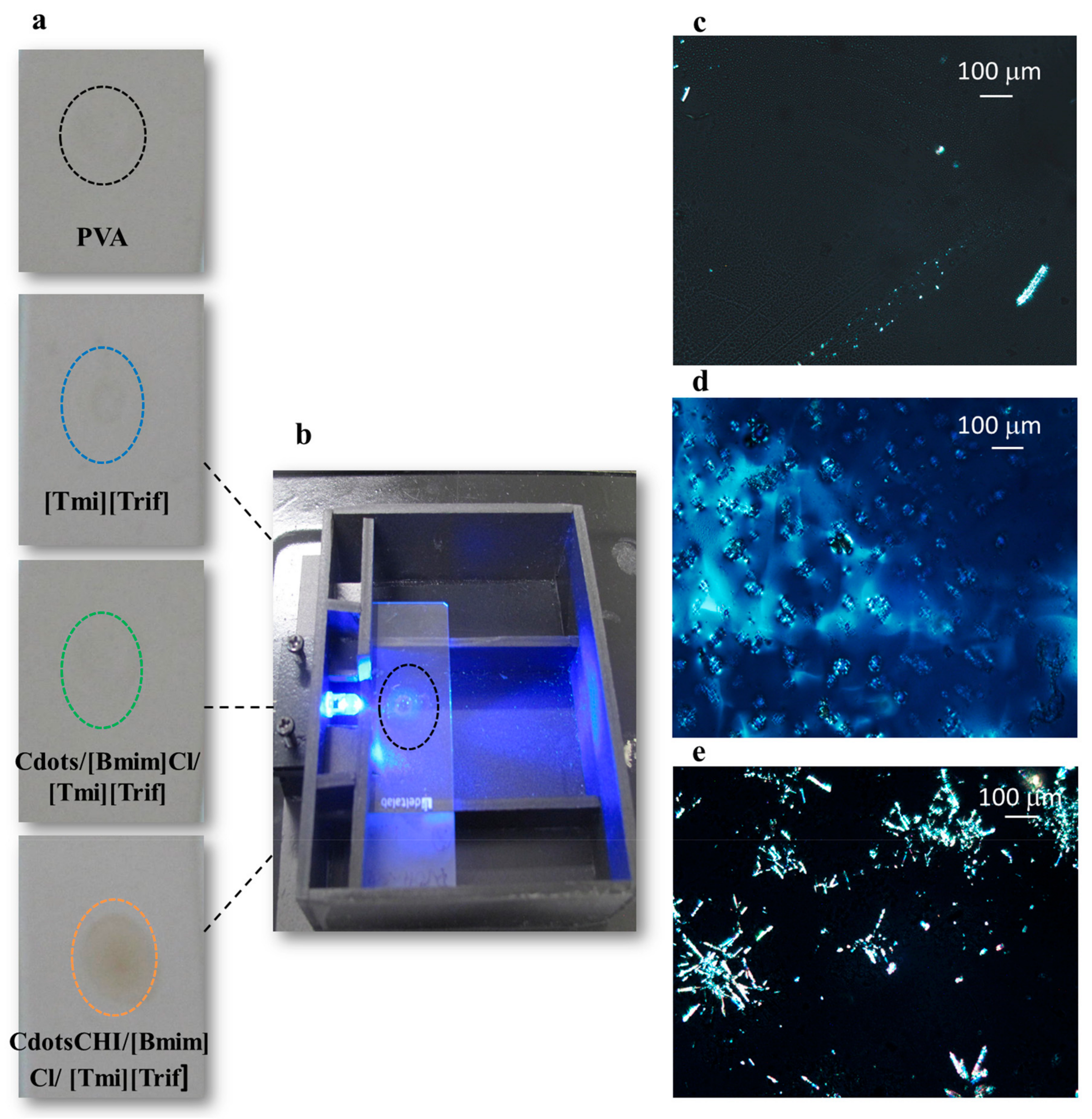
3.2. Nanofluids Immobilization on PVA Membranes
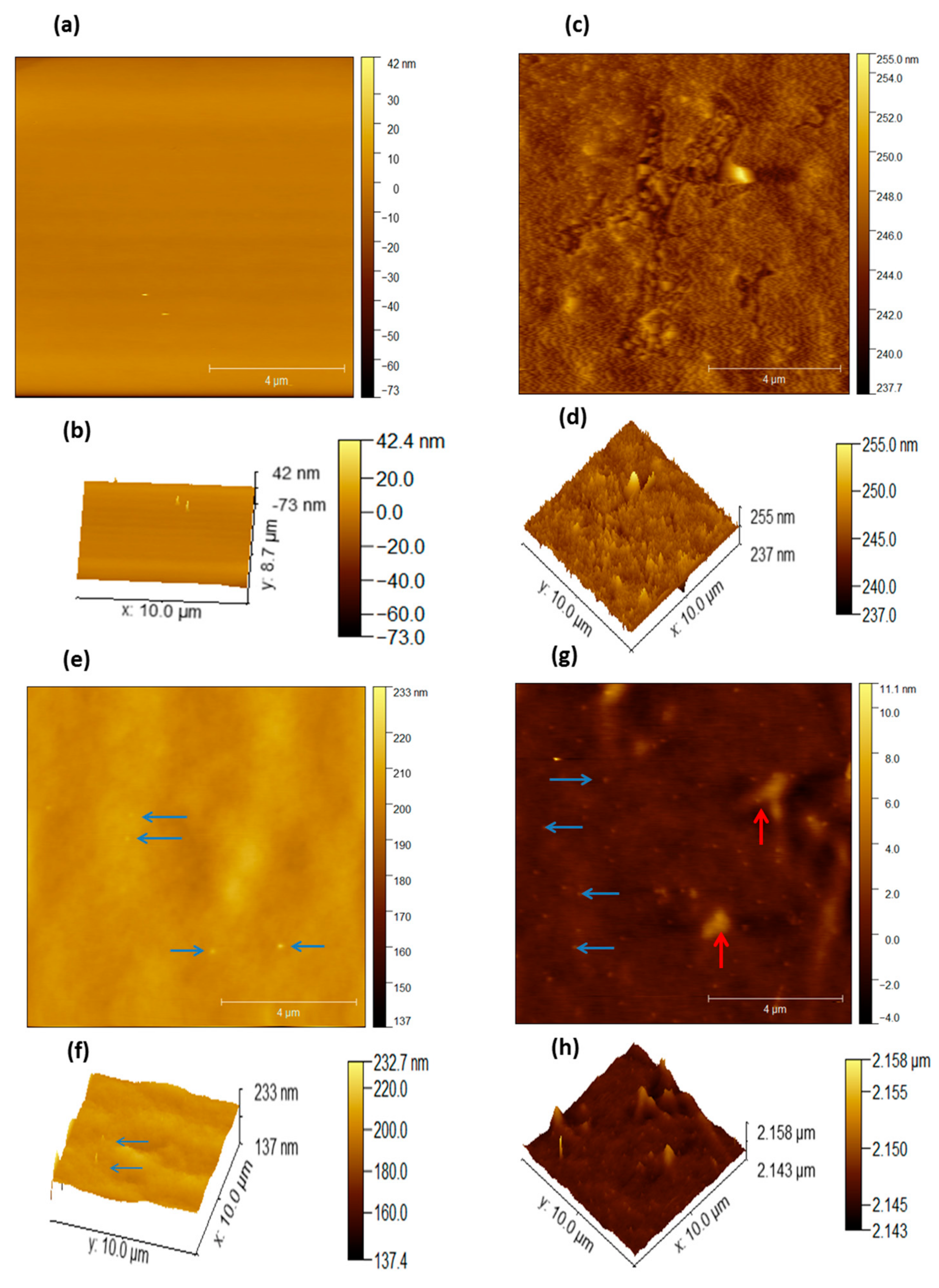
3.3. Membrane Morphology
3.4. Nanofluids’ Immobilization on PVA Membranes
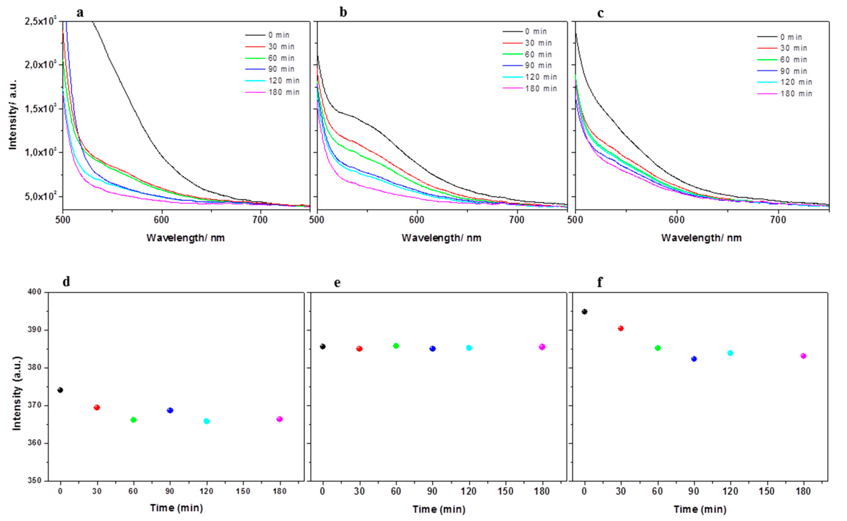
3.4.1. Study of the Nanofluids’ Leaching Profile from the PVA Membranes
3.4.2. Degree of Order of the Membranes
4. Conclusions
Author Contributions
Funding
Conflicts of Interest
References
- European Commission. “A Roadmap for Moving to a Competitive Low Carbon Economy in 2050”, Communication from the Commission to the European Parliament, the Council, the European Economic and Social Committee and the Committee of the Regions, COM (2011) 112. Available online: http://eur-lex.europa.eu/legal-content/EN/TXT/?uri=CELEX:52011DC0112 (accessed on 10 October 2019).
- Available online: https://www.nobelprize.org/prizes/chemistry/2019/summary/ (accessed on 10 October 2019).
- Placke, T.; Kloepsch, R.; Dühnen, S.; Winter, M. Lithium ion, lithium metal, and alternative rechargeable battery technologies: the odyssey for high energy density. J. Solid State Electrochem. 2017, 21, 1939–1964. [Google Scholar] [CrossRef]
- Inoue, T.; Mukai, K. Are all-solid-state lithium-ion batteries really safe? Verifcation by diferential scanning calorimetry with an all-inclusive microcell. ACS Appl. Mater. Interfaces 2017, 9, 1507–1515. [Google Scholar] [CrossRef]
- Bartsch, T.; Strauss, F.; Hatsukade, T.; Schiele, A.; Kim, A.Y.; Hartmann, P.; Janek, J.; Brezesinski, T. Gas evolution in all-solid-state battery cells. ACS Energy Lett. 2018, 3, 2539–2543. [Google Scholar] [CrossRef]
- Famprikis, T.; Canepa, P.; Dawson, J.A.; Islam, M.S.; Masquelier, C. Fundamentals of inorganic solid-state electrolytes for batteries. Nat. Mater. 2019, 18, 1476–4660. [Google Scholar] [CrossRef] [PubMed]
- The Future of Batteries Workshop-Preparing a European Initiative on Future Battery Technologies. Available online: https://ec.europa.eu/digital-single-market/en/news/future-batteries-workshop-preparing-european-initiative-future-battery-technologies (accessed on 10 October 2019).
- Dolatabadi, N.; Rahmani, R.; Rahnejat, H.; Garner, C.P. Thermal conductivity and molecular heat transport of nanofluids. RSC Adv. 2019, 9, 2516–5124. [Google Scholar] [CrossRef]
- Zheng, Z.; Jing, Q.; Xie, Y.; Zhang, D. An Investigation on the Forced Convection of Al2O3-water Nanofluid Laminar Flow in a Microchannel Under Interval Uncertainties. Appl. Sci. 2019, 9, 432. [Google Scholar] [CrossRef]
- Choi, S. Enhancing Thermal Conductivity of Fluids with Nanoparticles. In Developments and Applications of Non-Newtonian Flows; Siginer, D.A., Wang, H.P., Eds.; ASME FED: New York, NY, USA, 1995. [Google Scholar]
- Sarkar, J.; Ghosh, P.; Adil, A. A review on hybrid nanofluids: Recent research, development and applications. Renew. Sust. Energ. Rev. 2015, 43, 164–177. [Google Scholar] [CrossRef]
- Younes, H.; Ghaferi, A.A.; Saadat, I.; Hong, H.P. Nanofluids Based on Carbon Nanostructures. In Advances in Carbon Nanostructures; Sílva, A., Carabineiro, S., Eds.; BoD–Books on Demand: Norderstedt, Germany, 2016. [Google Scholar]
- Said, Z.; El Haj Assad, M.; Hachicha, A.A.; Bellos, E.; Abdelkareem, M.A.; Alazaizeh, D.Z.; Yousef, B.A.A. Enhancing the performance of automotive radiators using nanofluids. Renew. Sustain. Energy Rev. 2009, 112, 183–194. [Google Scholar] [CrossRef]
- MacFarlane, D.R.; Tachikawa, N.; Forsyth, M.; Pringle, J.M.; Howlett, P.C.; Elliott, G.D.; Davis, J.H.; Watanabe, M.; Simon, P.; Angell, C.A. Energy applications of ionic liquids. Energy Environ. Sci. 2014, 7, 232–250. [Google Scholar] [CrossRef]
- Lu, Y.; Korf, K.; Kambe, Y.; Tu, Z.; Archer, L.A. Ionic-Liquid–Nanoparticle Hybrid Electrolytes: Applications in Lithium Metal Batteries. Angew. Chem. Int. Ed. 2013, 53, 488–492. [Google Scholar] [CrossRef]
- Minea, A.A.; Sohel Murshed, S.M. A review on development of ionic liquid based nanofluids and their heat transfer behavior. Renew. Sustain. Energy Rev. 2018, 91, 584–599. [Google Scholar] [CrossRef]
- Gonçalves, H.M.R.; Pereira, R.F.P.; Lepleux, E.; Carlier, T.; Pacheco, L.; Pereira, S.; Valente, A.J.M.; Fortunato, E.; Duarte, A.J.; de Zea Bermudez, V. Nanofluid Based on Glucose-Derived Carbon Dots Functionalized with [Bmim]Cl for the Next Generation of Smart Windows. Adv. Sustain. Syst. 2019, 3, 1900047. [Google Scholar] [CrossRef]
- Gonçalves, H.M.R.; Pereira, R.F.P.; Lepleux, E.; Carlier, T.; Pacheco, L.; Duarte, A.J.; de Zea Bermudez, V. Non-Newtonian Thermosensitive Carbon Dots Nanofluid. 2020. recently submitted. [Google Scholar]
- Kim, S.Y.; Kim, S.; Park, M.J. Enhanced proton transport in nanostructured polymer electrolyte/ionic liquid membranes under water-free conditions. Nat. Commun. 2010, 1, 1–7. [Google Scholar] [CrossRef] [PubMed]
- Xiao, W.; Zhao, L.; Gong, Y.; Liu, J.; Yan, C. Preparation and performance of poly (vinyl alcohol) porous separator for lithium-ion batteries. J. Membrane Sci. 2015, 487, 221–228. [Google Scholar] [CrossRef]
- Havrdova, M.; Hola, K.; Skopalik, J.; Tomankova, K.; Petr, M.; Cepe, K.; Polakova, K.; Tucek, J.; Bourlinos, A.B.; Zboril, R. Toxicity of carbon dots – Effect of surface functionalization on the cell viability, reactive oxygen species generation and cell cycle. Carbon 2016, 99, 238–248. [Google Scholar] [CrossRef]
- Briscoe, J.; Marinovic, A.; Sevilla, M.; Dunn, S.; Titirici, M. Biomass-derived carbon quantum dot sensitizers for solid-state nanostructured solar cells. Angew. Chem. Int. Ed. Engl. 2015, 54, 4463–4468. [Google Scholar] [CrossRef]
- Sun, X.; Zhang, Q.; Yin, K.; Zhou, S.; Li, H. Fluorescent vesicles formed by simple surfactants induced by oppositely-charged carbon quantum dots. Chem. Commun. 2016, 52, 12024–12027. [Google Scholar] [CrossRef]
- Yu, P.; Wen, X.; Toh, Y.-R.; Tang, J. Temperature-Dependent Fluorescence in Carbon Dots. J. Phys. Chem. C. 2012, 116, 25552–25557. [Google Scholar]
- Ma, C.; Dai, K.; Hou, H.; Ji, X.; Chen, L.; Ivey, D.G.; We, W. High Ion-Conducting Solid-State Composite Electrolytes with Carbon Quantum Dot Nanofillers. Adv. Sci. 2018, 5, 1700996–1701005. [Google Scholar] [CrossRef]
- Figueiredo, K.C.; Alves, T.L.; Borges, C.P. Poly (vinyl alcohol) films crosslinked by glutaraldehyde under mild conditions. J. Appl. Polym. Sci. 2009, 111, 3074–3080. [Google Scholar] [CrossRef]
- Hoang, Q.B.; Mai, V.T.; Nguyen, D.K.; Truong, D.Q.; Mai, X.D. Crosslinking induced photoluminescence quenching in polyvinyl alcohol-carbon quantum dot composite. Mater. Today Chem. 2019, 12, 166–172. [Google Scholar] [CrossRef]
- Pandey, J.; Qayoom, F.M.; Shukla, A. Synthesis of silica immobilized phosphotungstic acid (Si-PWA)-poly (vinyl alcohol) (PVA) composite ion-exchange membrane for direct methanol fuel cell. Int. J. Hydrog. Energy 2014, 39, 9473–9481. [Google Scholar] [CrossRef]
- Kumar, V.B.; Sahu, A.K.; Mohsin, A.S.M.; Li, X.; Gedanken, A. Refractive-index tuning of highly fluorescent carbon dots. ACS Appl. Mater. Interfaces 2017, 9, 28930–28938. [Google Scholar] [CrossRef] [PubMed]
- Wu, S.; Li, W.; Zhou, W.; Zhan, Y.; Hu, C.; Zhuang, J.; Zhang, H.; Zhang, X.; Lei, B.; Liu, Y. Large-scale one-step synthesis of carbon dots from yeast extract powder and construction of carbon dots/PVA fluorescent shape memory material. Adv. Opt. Mater. 2018, 6, 1701150. [Google Scholar] [CrossRef]
- Yang, G.; Wan, X.; Liu, Y.; Li, R.; Su, Y.; Zeng, X.; Tang, J. Luminescent poly (vinyl alcohol)/ carbon quantum dots composites with tunable water-induced shape memory behavior in different pH and temperature environments. ACS Appl. Mater. Interfaces 2016, 8, 34744–34754. [Google Scholar] [CrossRef]
- Ambasankar, K.N.; Bhattacharjee, L.; Jat, S.K.; Bhattacharjee, R.R.; Mohanta, K. Study of electrical charge storage in polymer-carbon quantum dot composite. Chemistry Select. 2017, 2, 4241–4247. [Google Scholar] [CrossRef]
- Cui, Y.; Zola, R.S.; Yang, Y.C.; Yang, D.K. Alignment layers with variable anchoring strengths from polyvinyl alcohol. J. Appl. Phys. 2012, 111, 063520. [Google Scholar] [CrossRef]
- Nechifor, C.D.; Postolache, M.; Albu, R.M.; Barzic, A.I.; Dorohoi, D.O. Induced birefringence of rubbed and stretched polyvinyl alcohol foils as alignment layers for nematic molecules. Polym. Adv. Technol. 2019, 30, 2143–2152. [Google Scholar] [CrossRef]
- Nechifor, C.D.; Angheluta, E.; Dorohoi, D.O. Birefringence of etired poly (vinyl alcohol) (PVA) foils. Plast. Mater. 2010, 47, 164–166. [Google Scholar]
- Axenov, K.V.; Laschat, S. Thermotropic Ionic Liquid Crystals. Materials 2011, 4, 206–259. [Google Scholar] [CrossRef] [PubMed]
- Binnemans, K. Ionic liquid crystals. Chem. Rev. 2005, 105, 4148–4204. [Google Scholar] [CrossRef] [PubMed]
- Yuan, W.; Zhang, Y.; Cheng, L.; Wu, H.; Zheng, L.; Zhao, D. The Applications of Carbon Nanotubes and Graphene in Advanced Rechargeable Lithium Batteries. J. Mat. Chem. A 2016, 1–20. [Google Scholar] [CrossRef]


© 2020 by the authors. Licensee MDPI, Basel, Switzerland. This article is an open access article distributed under the terms and conditions of the Creative Commons Attribution (CC BY) license (http://creativecommons.org/licenses/by/4.0/).
Share and Cite
M. R. Gonçalves, H.; Neves, S.A.F.; Duarte, A.; de Zea Bermudez, V. Nanofluid Based on Carbon Dots Functionalized with Ionic Liquids for Energy Applications. Energies 2020, 13, 649. https://doi.org/10.3390/en13030649
M. R. Gonçalves H, Neves SAF, Duarte A, de Zea Bermudez V. Nanofluid Based on Carbon Dots Functionalized with Ionic Liquids for Energy Applications. Energies. 2020; 13(3):649. https://doi.org/10.3390/en13030649
Chicago/Turabian StyleM. R. Gonçalves, Helena, Susana A. F. Neves, Abel Duarte, and Verónica de Zea Bermudez. 2020. "Nanofluid Based on Carbon Dots Functionalized with Ionic Liquids for Energy Applications" Energies 13, no. 3: 649. https://doi.org/10.3390/en13030649
APA StyleM. R. Gonçalves, H., Neves, S. A. F., Duarte, A., & de Zea Bermudez, V. (2020). Nanofluid Based on Carbon Dots Functionalized with Ionic Liquids for Energy Applications. Energies, 13(3), 649. https://doi.org/10.3390/en13030649