Article

The Effect of Shank-Space on the Thermal Performance of Shallow Vertical U-Tube Ground Heat Exchangers

Department of Environmental Design, Faculty for the Built Environment, University of Malta, L-Imsida MSD 2080, Malta
*
Author to whom correspondence should be addressed.
Energies 2020, 13(3), 602; https://doi.org/10.3390/en13030602
Submission received: 3 December 2019 / Revised: 16 January 2020 / Accepted: 23 January 2020 / Published: 29 January 2020

Abstract

:
One parameter that may affect the performance of a ground source heat pump is the shank-space, the center-to-center distance between the two branches of a vertical U-tube used in a ground heat exchanger. A 3D steady-state computational fluid dynamics (CFD) model of a U-tube ground heat exchanger was used to investigate the influence of varying shank-space on the thermal performance of two isolated vertical shallow U-tubes, one 20 m deep and the other 40 m deep, given that most existing research focuses on systems making use of deeper boreholes. The models adopt an innovative approach, whereby the U-junction at the bottom of the U-tube is eliminated, thus facilitating the computational process. The results obtained show that, although the temperature drop across the U-tube varies for different shank-spaces and is lowest and highest for the closest and the widest shank-spaces, respectively, this temperature drop is not linear with increases in shank-space, and the thermal performance improvement drastically diminishes with increasing shank-space. This indicates that, for shallow U-tubes, the temperature drop is more dependent on the length of the pipework.

1. Introduction

In Europe, buildings currently account for 40% of the total energy consumption [1] with 50% of the energy consumed being utilized for space heating and cooling [2]. Increasing the energy-efficiency of buildings, including the services utilized for heating and cooling, is therefore essential. Curtailing the energy consumed for meeting the demands for heating and cooling can be achieved in a variety of ways. One of the approaches proposed is energy saving through the adoption of energy-efficient technologies [3].
One technology that has been proven capable of reducing energy consumption in buildings is the ground source heat pump, which is capable of providing heating and cooling with an improved coefficient of performance compared to conventional air sourced systems [4].
Using electricity as input, ground source heat pumps utilize the low-temperature geothermal energy present in the ground as a sink to dump excess heat or as a source from which to extract the required heat. The fact that, below a certain depth, the ground temperature is constant throughout the year ensures that a more stable and higher coefficient of performance can be achieved all year round [5,6]. Given that ground source heat is available everywhere, irrespective of climate or location, ground source heat pumps have become a well-established technology for space heating and cooling worldwide [7].

2. The Ground Source Heat Pump—A Short Review

A ground source heat pump consists of three principal components, namely, a heat pump that uses electricity to move heat to and from the conditioned space; an indoor heating/cooling distribution system that conditions the indoor space; and a ground heat exchanger (GHE) [8].
The ground heat exchanger is at the heart of the system and normally consists of an underground circuit of pipes through which a circulating liquid absorbs or rejects heat from or to the ground. The exchanger can be of the open or the closed loop type based on whether the circulating fluid enters in contact with ground or not and—more importantly—is installed vertically or horizontally.
Notwithstanding their higher costs due to the drilling required [9], vertical systems are typically the preferred setup due to the fact that ground temperatures get increasingly stable with depth [10,11]. One popular layout of a vertical ground heat exchanger system consists of a pair of parallel pipes connected at the bottom by a U-shaped connector installed inside a borehole with a typical diameter of 100–150 mm and depths of up to 200 m [12], although borehole depths of between 50 m and 150 m are the most commonly used [13].
Vertical ground heat exchangers can exist as a single borehole or, more typically, as an array of boreholes depending on the heating/cooling demand [14]. As a general rule of thumb, the distance between adjacent boreholes is usually not allowed to be less than 4.5–6 m in order to prevent thermal interactions between boreholes [8,15].

3. Parameters Affecting the System Performance

The efficiency of a ground source heat pump is dependent on the heat exchange process between the fluid circulating through the piping inside the ground heat exchanger and the ground—basically the borehole thermal resistance [16]. The borehole thermal resistance is in turn influenced by several geometrical, thermo-physical, and operational parameters. A thorough understanding of these factors is therefore crucial in enhancing the performance of such a system. Javed and Spitler in [17] provide a most up to date comparative study of a number of analytical methods used for calculating borehole thermal resistance, also discussing the type of approximations typically employed and the accuracy of each method analyzed.

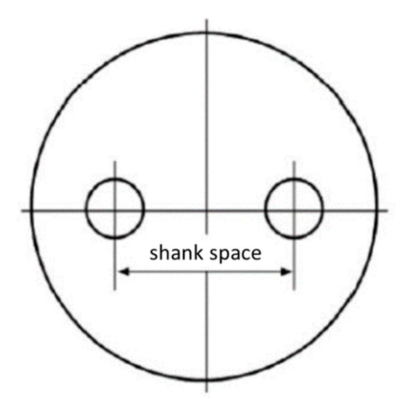
3.1. Effect of Shank-Space on System Performance

One of the parameters that affects the borehole thermal resistance and hence the performance of a U-tube ground heat exchanger is the shank-space [18], that is, the center-to-center distance between the inlet and the outlet pipes of the U-tube, as shown in Figure 1.
Literature [19,20,21] shows that the ideal arrangement of the U-tube inside the borehole is when the two vertical pipe branches are as close as possible to the borehole wall and therefore the furthest apart from one another. Independently of the other parameters, this configuration would result in a low borehole thermal resistance. In reality, as discussed by Makasis et al. [22], vertical pipes inside a borehole are seldomly perfectly aligned, and the separation distance often varies with depth. Makasis et al., however, also explain how often the use of spacers placed at regular intervals ensures a higher level of confidence in a commonly made assumption around which most analytical and numerical work on vertical pipe separation is based, that is, that pipes are equally spaced along the entire depth of the borehole. This research follows that same assumption.
Given that the issue of variations in shank-space revolves around the phenomenon of thermal resistance and thermal short-circuiting, this is often studied in conjunction with variations in other parameters, such as borehole depth, borehole radius, fluid mass flow rate, U-tube radius, U-tube pipe material, and grout thermal conductivity among others [23]. Recent work done by Zhou et al. [24], for example, uses the Taguchi method to find the effect of eight parameters (including most of the above mentioned) on the thermal resistance, concluding that the shank-space has the most substantial impact on the thermal performance of ground heat exchangers. Work done by Zanchini and Jahanbin [25] relates the effect of shank-spacing and borehole length to the mean fluid temperature inside a double U-tube borehole, an essential parameter in the design of ground-coupled heat pumps. Also, work done by Naldi and Zanchini [26] shows how a higher shank-space coupled with a higher Reynolds number makes a single U-tube ground heat exchange perform on the same level as a double U-tube ground heat exchanger.
Other studies found in literature regarding the effects of variations in shank-space on the performance of U-tube ground heat exchanger reveal that the contribution from the shank-space may be highly relevant in certain cases but less important or negligible in others [27,28].
Witte [27] carried a sensitivity analysis on borehole performance in which the effects of several parameters both in isolation as well as in conjunction with each other parameters were numerically investigated. Witte observed that the effects of variations in shank-space are more prominent for fluid laminar flows, suggesting that the shank-space should be as large as possible in case of laminar flow, while for turbulent flows, the shank-space is irrelevant.
Zheng et al. [28] conducted a numerical analysis using MATLAB on the factors that affect U-tube ground heat exchangers. The study noted that, in order to ensure greater heat flow and reduce the probability of thermal short-circuiting, the shank-space should ideally be in the range of 100–200 mm. Other literature sources, such as that by Cui et al. [29], however, discuss that the effect of thermal short-circuiting is actually negligible if the shank-space is higher than 60 mm.
Most of the research carried out in this area has focused on vertical boreholes with typical depths of 50 m and over, as commercially these are the ones that are used primarily to ensure that enough contact area to reject or absorb the heat is available. However, reaching such depths is not always possible, and other design limitations such as the requirement for limited interaction with the water table [30,31] or indeed the need to reduce drilling costs [32] may require that a system makes use of shallower heat exchangers (up to 50 m depth).
Given such a limitation, researchers often tend to consider completely different alternatives to the conventional vertical U-tube design. Such alternatives include relatively standard horizontal or slinky systems [33], as well as more novel and advanced proposals, including underground thermal batteries making use of phase change materials [34]. Notwithstanding this, interest in the vertical U-tube design is still high; fairly recently, a number of studies have been published focusing specifically on shallow vertical ground heat exchangers. One such study is a piece of literature by Tang and Nowamooz [35] that investigates the factors influencing the performance of shallow vertical borehole heat exchangers, including the effect of shank-space. Their study specifically looks at the effect varying-shank space has for one single depth of 20 m in different soil typologies. As is discussed in Section 4, the research presented in this paper builds on such research by investigating the effect of certain geometrical parameters (shank-space, depth, and borehole spacing) and their relationship, specifically in the context of shallow ground heat exchangers. This is done primarily through the use of a 3D steady-state numerical model.

3.2. Effect of Spatial Arrangement and Borehole Spacing

In large scale installations, there is usually the need to have more than one borehole—even tens of them—to cater for the pipework surface area required to meet a specific heat exchange demand. If land is restricted, the number of U-tubes that can be feasibly installed may limit the ground source heat pump to meet only a portion of the thermal load. When multiple ground heat exchangers are used, they are usually arranged in an array formation called a borehole field.
All the boreholes are grouped into smaller arrays, where each array is operated by a single heat pump. In addition to the parameters that affect the thermal performance of a single ground heat exchanger, such as thermal conductivities of ground and grout, shank-space, borehole depth, and fluid flow velocity, the thermal interaction between boreholes is another parameter that has an impact on the system overall performance. Therefore, the allocation of sufficient separation distance between boreholes inside an array becomes an important issue [36].

4. Scope of Research

In response to the increasing need for utilizing shallow ground heat exchangers, the research hereby being presented deals with analyzing geometric parameters specific to shallow, vertical U-tube ground heat exchangers and related borehole arrays. Specifically, the aim of this research is twofold.
The research first focuses on the micro-scale and evaluates how the performance of an isolated vertical U-tube ground heat exchanger having a fixed borehole diameter changes with different values of shank-space and (shallow) depth. The second part of the research complements the first, this time on a macro-scale, as it is intended to evaluate how the performance of the same shallow vertical ground heat exchanger modeled and located centrally within an infinitely-large square array of boreholes varies with changes in borehole spacing.

5. Methodology

The research presented in this paper utilizes a parametric analysis, whereby a number of parameters were varied to check for their resultant effect on the performance of shallow, vertical U-tube ground heat exchanger. As discussed, the two parameters considered were the shank-space in an isolated vertical U-tube heat exchanger and the borehole spacing in a multi-borehole array having an infinite number of shallow vertical ground heat exchangers similar to the isolated vertical U-tube ground heat exchanger.
The study sought to identify relative changes in the thermal performance of the heat exchanger triggered by variations in the parameters outlined. In line with this principle, and since the coefficient of performance of a ground source heat pump is directly related to the temperature difference between the inlet and the outlet of the ground heat exchanger, the thermal performance losses or gains were primarily assessed by noting the relative changes in the mean temperature difference between the system inlet and outlet (temperature drop) for different values of the variables considered. A simple energy analysis is also presented as part of the analysis in the results and discussion section.
The effects of the attributes mentioned above were investigated numerically by means of computational fluid dynamics (CFD) simulations. Whereas in situ experiments, referred to as thermal response tests [11], are frequently used to characterize the performance of ground heat exchangers, given the advancement of numerical modeling, it has now become customary to use numerical modeling, either to complement these in situ analysis [37] or else to extend validated models to research new aspects. Numerical modeling was carried out in ANSYS FLUENT 16.2 [38], which was used to perform three-dimensional (3D) steady-state CFD calculations in order to simulate the heat transfer process between the fluid and the grout/ground combination and the resulting temperature distributions for the various ground heat exchanger configurations.

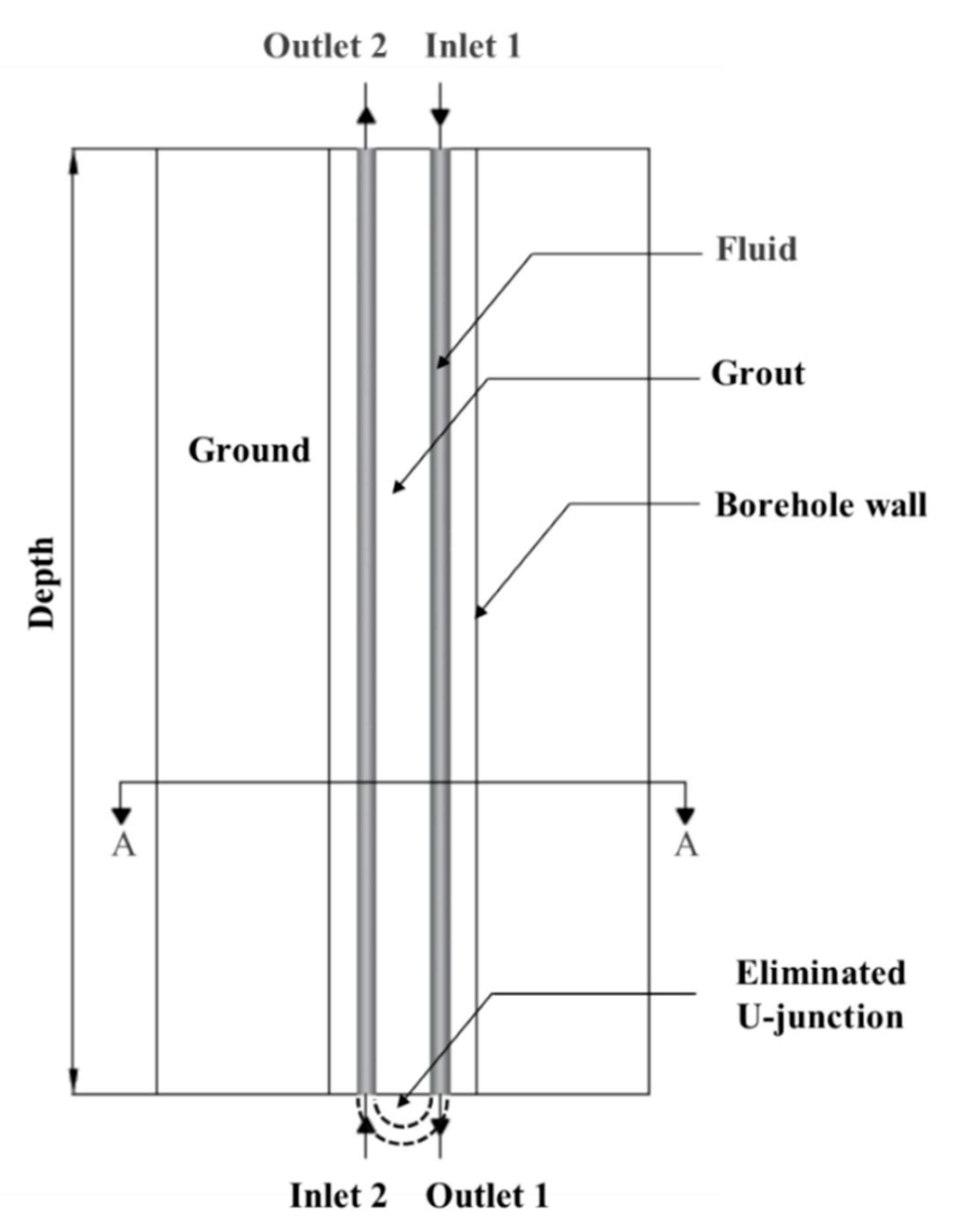
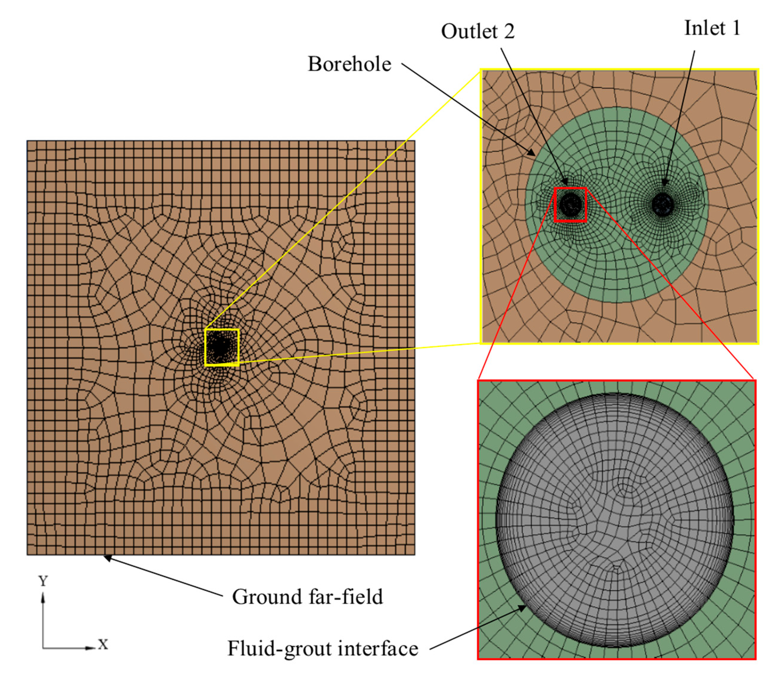
5.1. Computational Domain of the Isolated Ground Heat Exchanger

A 3D model of an isolated 20 m deep U-tube ground heat exchanger was created using ANSYS. Normally in literature, 3D simulations involve modeling a ground heat exchanger in its entirety as opposed to two-dimensional (2D) numerical simulations, in which the U-tube ground heat exchanger is modeled by taking a horizontal cross-section at a particular depth along the length of the borehole where the ground temperature and the temperature of the fluid in the downward and the upward pipes are assumed to have reached stabilized values [39]. In this specific case, however, the 3D U-tube ground heat exchanger was modeled as shown in Figure 2, that is, eliminating the U-shaped connector at the bottom of the U-tube.
The motive behind this modification was to simplify the model, consequently reducing the modeling/computation time significantly. The removal of the U-junction altered the nature of the flow that would otherwise have developed in an unbroken loop of pipes and introduced an intermediate outlet (i.e., Outlet 1) and inlet (i.e., Inlet 2), as shown in Figure 2.
To ensure the validity of the proposed model, the model was validated using the experimental work done by Borg [40] on a 20 m deep ground heat exchanger, and the subsequent (numerical) simulation work done by Sciberras using a CFD model of said setup [41].
A number of checks were performed to ensure that the proposed model without the U-tube connector was valid, including ensuring that the fluid entering Inlet 2 developed into a fully turbulent flow within the total length of the pipe and direct comparison with the results obtained by Sciberras [41] in his model. In the first instance, the hydrodynamic entry length was around 10 times the pipe diameter, that is, 0.36 m (internal diameter of the pipe was 0.036 m), meaning that the flow attained turbulent properties within the first 2% of the pipe length. The second check was a direct comparison with the temperatures obtained by Sciberras in [41]. For the same shank-space, in the model proposed in this paper, the resulting temperatures at Outlet 1 and Outlet 2 were both observed to be less than 0.0007% off from the temperatures obtained by Sciberras’ model. This result indicated that the elimination of the U-junction had no significant impact on the simulated temperature profile of the carrier fluid.
Considering these two checks, it was reasonably assumed that omitting the U-junction from the model does not have significant repercussions in terms of overall temperature difference between Inlet 1 and Outlet 2, and given the relatively small shank-spaces being investigated in this research (and typical of U-tubes), such an assumption was considered to hold true for all subsequent simulations involving different shank-spaces.
The computational domain for the isolated ground heat exchanger, shown in plan in Figure 3, consisted of four sub-domains: two fluid sub-domains representing the carrier fluid flowing within the two branches of the U-tube and two solid sub-domains representing the infilled grout and the surrounding ground whose adopted volume had the shape of a three-dimensional box (cuboid) measuring 60 × 60 m.
The average temperature of the two outlets (Outlet 1 and Outlet 2) was used to assess mesh convergence. Mesh independence was guaranteed by checking that the average temperatures did not vary by more than 1%, as used in Hajdukiewicz et al. [42] and Qi et al. [43]. The resulting converged mesh involved 1.16 million cells. The convergence criteria used in the present study was that all the residuals were at least less than 1 × 10⁻⁶ for both the flow and the energy equations (for the energy equation, the residuals were of the order of 10−9) and that the temperature at the two monitored points (Outlet 1 and Outlet 2) leveled to a constant value and did not change with further iterations.
The borehole, which was positioned along the centroidal axis of the ground volume, had a fixed diameter of 300 mm and extended to the bottom surface of the ground domain. Being one of the parameters whose value was varied as part of this research, two values for (shallow) depth were considered, specifically 20 m and 40 m. The pipes were modeled having an outer diameter of 40 mm and a wall thickness of 2 mm. The physical properties of the ground, the backfill material, the pipe material, and the carrier fluid are summarized in Table 1.
A dedicated explanation is required for the artificial high conductivity grout used in the analysis, as, in practice, grout mixes can attain conductivities not exceeding 2.5 W/mK. It is well known that the effect of the grout thermal conductivity does not greatly influence the grout overall thermal resistance once a certain value is exceeded (Javed and Spitler [17]). Javed and Spitler [17] in fact show by comparing various calculations methods for grouted single U-tube ground heat exchangers that, beyond this 2.5 W/mK value, increasing the conductivity does not help much to decrease thermal resistance, and the latter remains rather constant with increasing conductivities. Given that the purpose of this study was to understand the effect of shank-spacing without varying the other parameters, it was decided to isolate the effects of the grout thermal conductivity using an artificially high value, which was chosen in a way to give minimal change in the overall grout resistance. This becomes clear from the grout resistance, Rg, calculated on the basis of a radial one-dimensional analysis, which shows that resistance is an inverse function of the conductivity:
R g = 1 2 π λ ln ( R b r e q )
where λ is the grout thermal conductivity, R b is the borehole radius, and r e q is the equivalent radius of the U-tube pipes. The latter parameter has been expressed differently by various authors with the expression from Claessen and Dunant [44] using the equivalence between the total surface area of both pipes resulting in:
r e q = 2   R p
where Rp is the pipe radius. For this work, the relationship of Gu and O’Neal [45] is more appropriate since it includes the effect of shank spacing, s:
r e q =   R p s
The mathematical limit, as the equivalent radius approaches Rb, gives the limiting value of zero for the logarithmic term giving negligible resistance.

5.2. Establishing the Boundary Conditions

Inlet 1 was assigned a velocity inlet boundary condition, and the temperature of the fluid was set at an initial 40 °C. The velocity inlet boundary condition was used as the flow inlet boundary condition because the fluid velocity magnitude and direction together with the temperature at that location were known.
The fluid was set to flow at a rate of 10 l/min, the same flow rate utilized by Borg [40] in his field experiments and Sciberras [41] in his numerical approach. Likewise, the secondary inlet (Inlet 2) was given the same boundary condition as Inlet 1 except that the temperature of the fluid was set to be equal to the temperature of Outlet 1. This was achieved by means of an automated user defined function that used the iterative results of the temperature of Outlet 1 as the input temperature of Inlet 2.
The two outlets (Outlet 1 and Outlet 2) were set as pressure outlets specified by a static pressure of 0Pa and a backflow total temperature of 27 °C. The top surfaces of the ground and the grout domains were assigned as a wall and set to allow a heat transfer by convection with a heat transfer coefficient of 4.345 W/m2K and a free stream temperature of 27 °C. The bottom surfaces of the solid domains were specified as being adiabatic. The far-field ground surfaces were also set as adiabatic boundary surfaces.

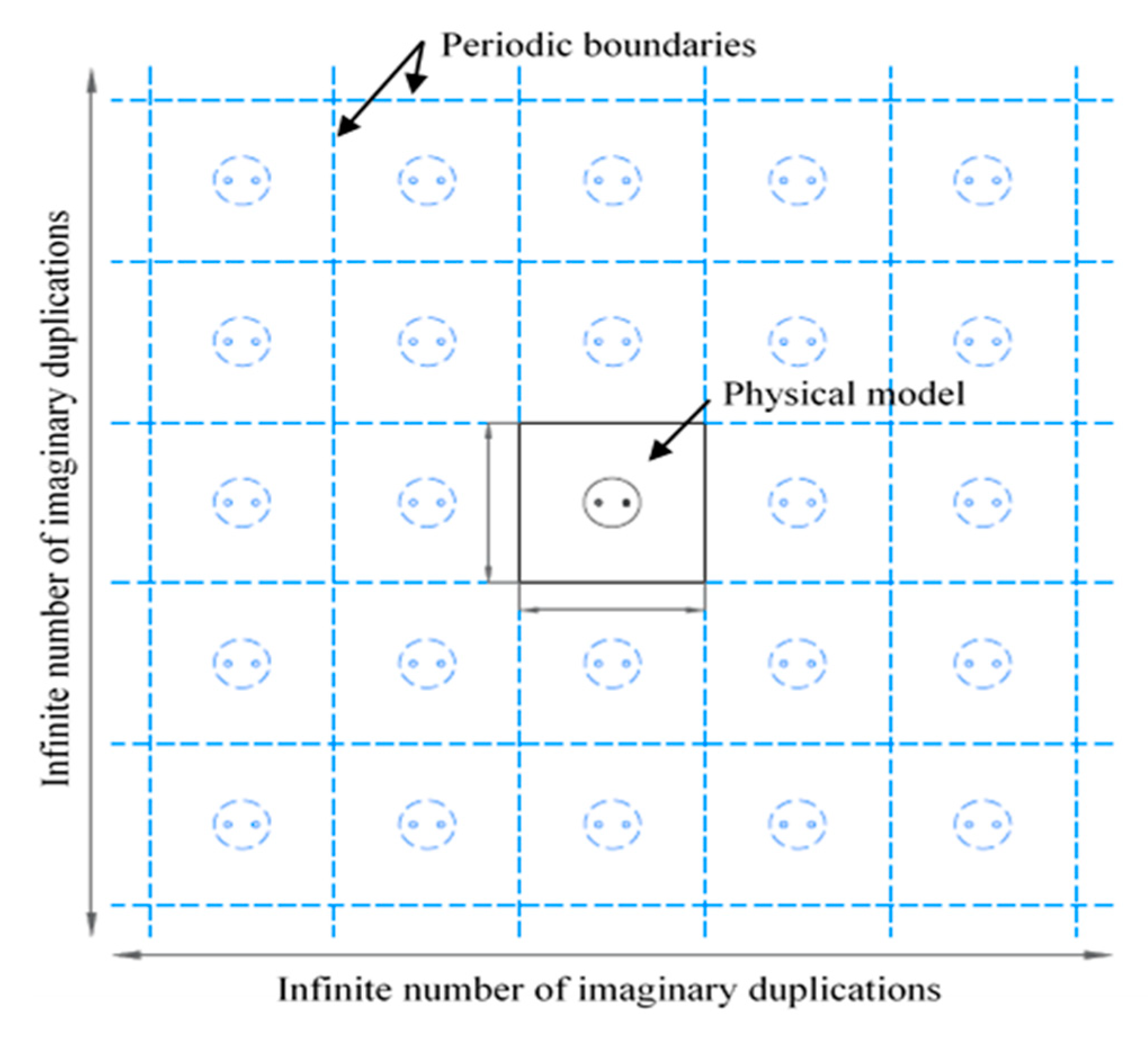
5.3. Computational Domain of the Ground Heat Exchanger Array

To analyze the effects of borehole spacing (center-to-center distance between two adjacent, collinear boreholes) in an array of boreholes, the base model was positioned centrally in a square array having an infinite number of boreholes in the two orthogonal directions. The geometry of the array formation was accomplished by means of a periodic boundary condition applied to the outer edges of the ground domain, as shown in Figure 4. The smallest borehole spacing was chosen to be 5 m in accordance with recommendations from literature and was increased in increments of 5 m to 10 m and 15 m.

5.4. Solution Methods

The solver of the commercial code ANSYS FLUENT 16.2 was used to calculate the coupled heat transfer process between the carrier fluid and the solid domains. The Navier–Stokes and energy equations solved are as follows:
Continuity equation : u x + v y + w z = 0
Momentum equation : ρ v v = p + μ 2 v + F
Energy equation : ρ c p ( T u x + T v y + T w z ) = x ( k T x + u τ ) + y ( k T y + v τ ) + z ( k T z + w τ )
where x, y, and z are the Cartesian coordinates, and u, v, and w are the velocities in x, y, and z directions. v is the velocity vector, ρ is the density, p is the pressure, µ is the dynamic viscosity, and F is the body force vector (here taken to be zero). T is the temperature, k is the thermal conductivity of air, and τ is the viscous shear stress. These governing equations were iteratively solved by the finite volume method with the SIMPLE pressure–velocity coupling algorithm and discretized by the second order upwind scheme. All simulations were initially solved by the standard k-ε turbulence model until the convergence criteria were met. Following this, the turbulence model was changed to the shear stress transport (SST) k-ω model and iterated until convergence was reached again.

6. Results and Discussions

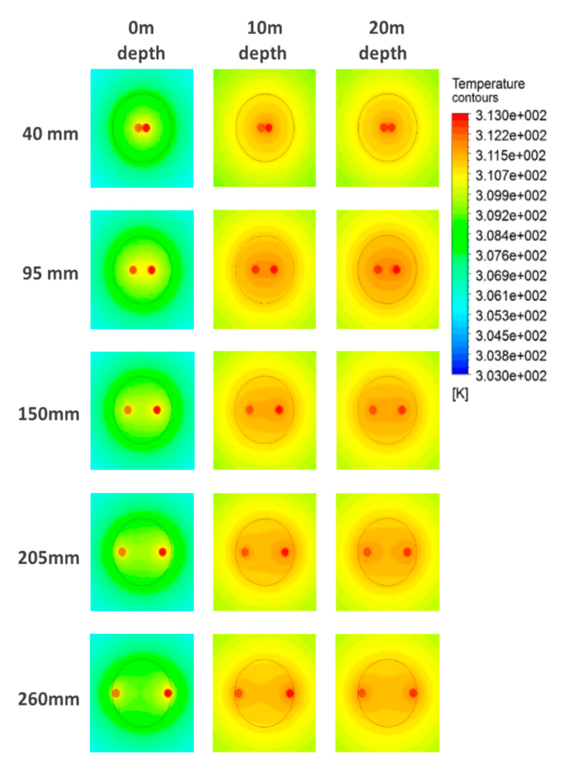
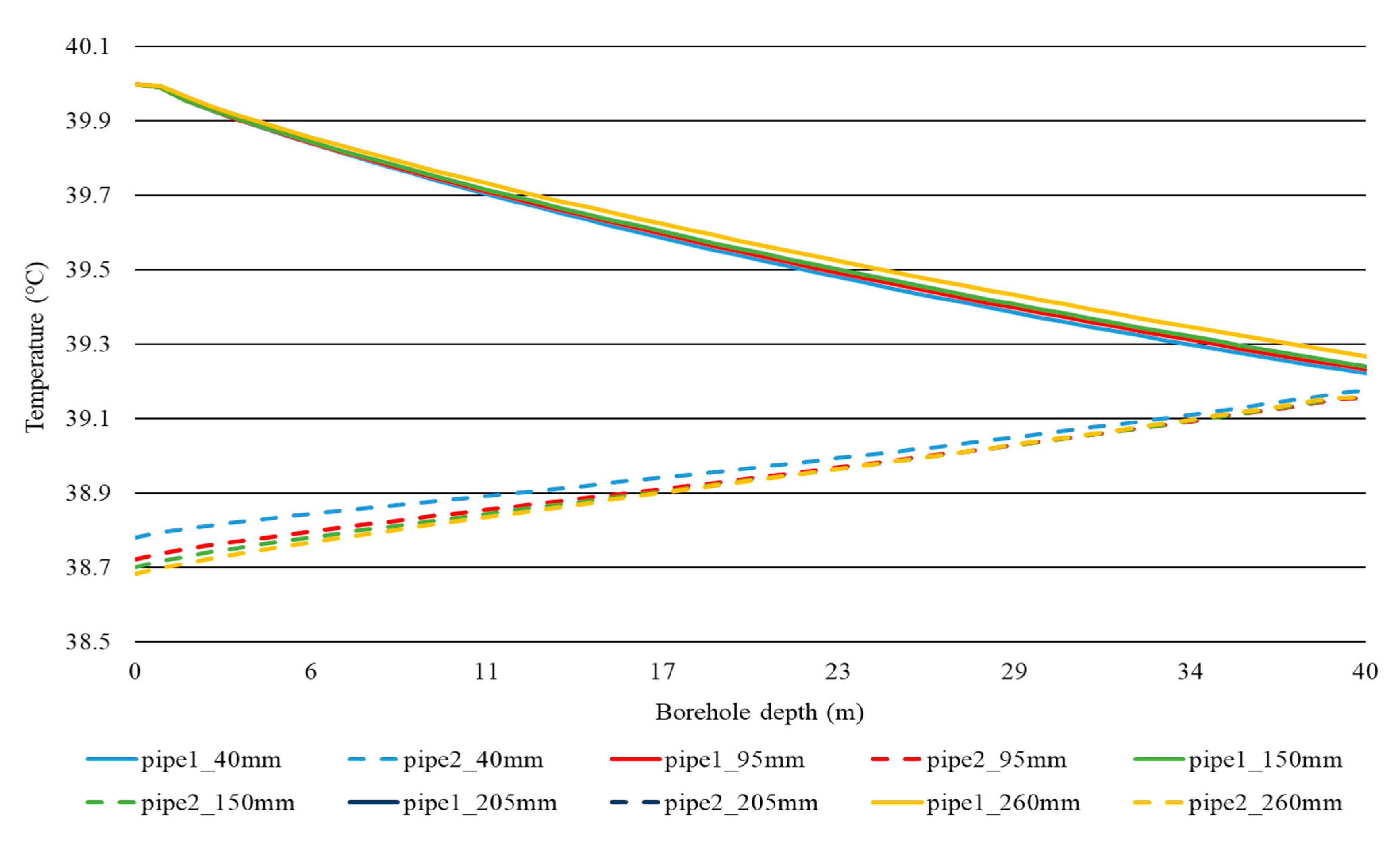
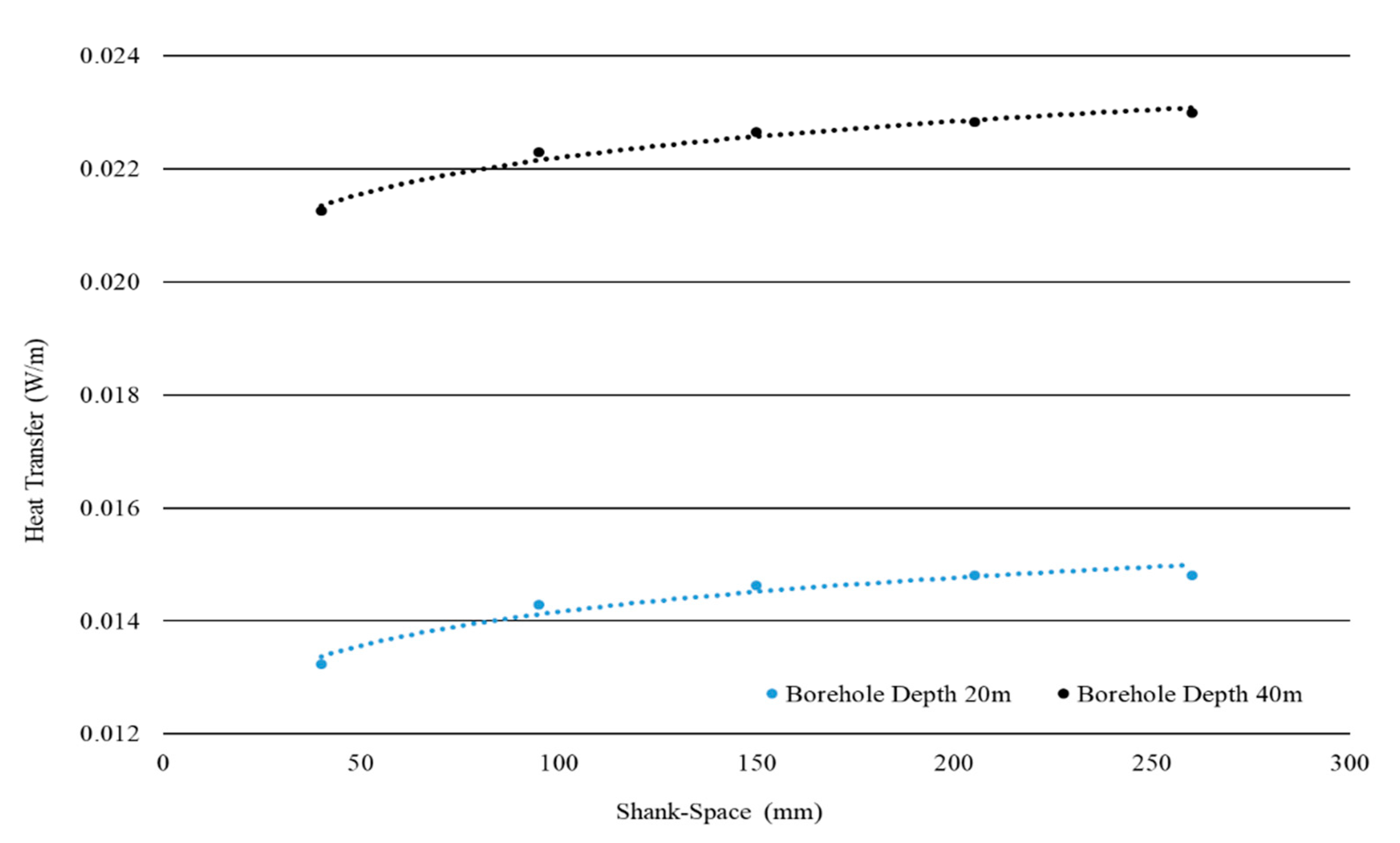
6.1. Varying the Shank-Space for a 20 m Borehole

For the 20 m deep ground heat exchanger apart from the 150 mm used to validate the model without the U-junction, four other different cases were considered, namely, two extreme situations in which the pipes touched each other and the borehole wall had shank-spaces of 40 mm and 260 mm, respectively, and another set of intermediate shank-spaces located midway, that is, 95 mm and 205 mm. The temperatures at the four points of interest for each of the shank-spaces simulated are presented in Table 2.
The temperature drop across the U-tube ground heat exchanger (difference between Inlet 1 and Outlet 2) between the two extreme shank-spaces investigated was found to be 0.09 °C, equivalent to an 11.8% difference. As one can expect, the temperature drop increased with increasing shank-spacing, however, this increase was found not to be linear. As the shank-space increased from 40 mm to 95 mm, the temperature drop increased by 7.9%, whereas with the 150 mm shank-space, the temperature drop increased only by 2.4% compared to the 95 mm shank-space. The change in temperature drop was then found to diminish drastically beyond the 150 mm shank-space. In fact, the 205 mm and the 260 mm shank-spaces resulted in no change at all, indicating that, between the 150 mm and 205 mm, the ground heat exchanger reached maximum performance and further increases in shank-space would not yield further improvement.
Figure 5 shows the variation of the fluid temperature along the center-line of the fluid domains with borehole depth. The fluid temperature varied more or less linearly with pipe length for all shank-spaces but at slightly different gradients. A larger shank-space also produced a slightly shallower gradient. It could also be observed that variations in shank-space only primarily affected the upward moving fluid domain (pipe2), as the decrease in temperature in the downward moving fluid domain (pipe1) was practically equal for all five shank-spaces.
The temperature distribution within the ground heat exchanger components on three horizontal x-y planes located at different depths for the five simulations outlined above are presented in Figure 6. Due to the relatively small temperature drops obtained in all five simulations, the temperature distribution in the outward radial direction exhibited a typical sharp contrast between the temperature of the fluid domains and the temperature of the surrounding grout and ground domains. This contrast was highest at the top but decreased gradually with depth.
The plots show that, for the 40 mm shank-space, the temperature contours in the region of the borehole cross-section were more or less circular, while with increases in shank-space, the temperature contours around the fluid domains took the shape of an oval that encapsulated the upward and the downward pipes. This phenomenon was observed throughout the whole depth of the borehole, bar the larger shank-spaces (205 mm and 260 mm), where the egg-shaped temperature contours started to separate in two, forming two almost independent circular contours around the fluid domains, as was observed for the 260 mm shank-space. The grout temperature in the central part was therefore lower compared to that for the other shank-spaces.
These results confirmed the presence of thermal short-circuiting, implying that the pipes were not only exchanging heat with the grout but also exchanging heat with one another, thus deteriorating the thermal performance of the ground heat exchanger. Thus, the loss in performance associated with variations in shank-space could be attributed to the effects of thermal short-circuiting. As the entire length of pipe simulated was only 40 m long, the temperature drop between the inlet and the outlet was also small, and thus the thermal short-circuiting effect witnessed in these simulations was small.

6.2. Varying the Shank-Space for a 40 m Borehole

The second set of results obtained for a borehole depth of 40 m, shown in Table 3, showed similar trends to those obtained for the 20 m borehole, although with marginally higher temperature drops. The fluid temperature variation with depth is shown in Figure 7.
As can be seen from the results obtained, the temperature drop for all shank-spaces was marginally higher than those obtained for the 20 m deep borehole. This is to be expected, given the larger contact area available for heat transfer. However, also noticeable was the fact that, similarly to the 20 m deep borehole, as the shank-space increased, the temperature drop increased in a non-proportional manner with a higher increase between the 40 mm and the 95 mm shank-spaces compared to the practically non-existent increase between the 205 mm and the 260 mm shank-spaces.
When the temperature drops are compared across borehole depth, as shown in Table 4, it becomes apparent that the temperature drop between inlet and outlet of the ground heat exchanger was, in fact, more dependent on the length of the pipework rather than the effect of increasing shank-space. In this case, the depth-based improvement was constant, irrespective of shank-space.

6.3. Isolated Borehole Energetic Analysis

A simple analysis of the total heat energy dissipated into the ground is given by the heat released from both supply and return sides of the U-tube. The heat transfer per unit length is given by:
q = m ˙ c p T L
where m ˙ is the mass flow rate, c p is the specific heat capacity, T is the change in temperature from inlet to outlet, and L is the total length of pipe equivalent in this case to the total U-tube depth. The results for heat transfer against shank-space are shown in Figure 8.
As was expected given that the analysis is for two single isolated ground heat exchangers, the quantities were rather low. Nonetheless, the general trends are evident. The heat transfer per unit length for both ground heat exchangers increased as the shank-space widened until the curves reached an asymptotic value. The findings are also in line with what was discussed in terms of grout thermal conductivity in that, despite the idealistically high conductivity of grout material that was utilized for the simulation, the pipe shank-space still played a role on the system energetics.

6.4. Effect of Borehole Spacing

This last part of the research utilized the modeled U-tube ground heat exchanger to extend the work done on a single isolated borehole to a more realistic array of boreholes, hence evaluating the overall thermal performance of the modeled U-tube ground heat exchanger under the effect of different borehole spacing.
To conduct this second part of the research, as discussed earlier, an array with an infinite number of boreholes in the two orthogonal directions was modeled. Three cases of borehole spacing were considered, that is, 5 m, 10 m, and 15 m. The borehole characteristic utilized for the modeling of the array was the 20 m borehole having a shank-space of 150 mm.
Arguably, being a theoretical exercise, the results presented here take into consideration only the case where a constant flow is present and do not take into consideration aspects such as the seasonal variation in cooling and heating loads, which might affect the parameters being studied, nor the long term interaction between the ground and the boreholes.
In analyzing the results, as shown in Table 5, one necessarily needs to do a comparison with the isolated case scenario (borehole 20 m; shank-space 150 mm) utilized for the modeling of the U-tube ground heat exchanger. Using the temperature drop obtained for the isolated case scenario, that is, 0.84 °C, as the reference value, it was immediately noticeable that, compared to the isolated case, there was a significant loss in the thermal performance, measured as temperature drop between Inlet 1 and Outlet 2. In fact, compared to the isolated case scenario, the performance loss due to the three boreholes spacing investigated varied between 78% for the 5 m borehole spacing, 52% for the 10 m borehole spacing, and 32% for the 15 m borehole spacing.
As expected, in a borehole array, thermal interference between boreholes occurs, with the extent of this thermal interference, of course, being in part related to the proximity of the boreholes to one another. The further apart the boreholes are, the smaller this thermal interference will be. Interestingly, similarly to the shank-space case, the relationship between thermal performance changes appears not to be linear, with a more significant and rapid loss in performance occurring once the boreholes were modeled to be placed very close to one another.

7. Conclusions

The research presented in this paper looked at the effect shank-space has on the performance of shallow vertical U-tube ground heat exchangers. Using the computational fluid dynamic tool ANSYS, two vertical U-tube ground heat exchangers were modeled, one 20 m deep and the other 40 m deep. For each system, the shank-space was varied between a minimum of 40 mm to a maximum of 260 mm, and the resultant temperature drop between inlet and outlet was simulated. Differently from most other modeling approaches involving U-tube ground heat exchangers, the 3D U-tube heat exchanger model was modeled without the U-shaped connector at the bottom of the U-tube. Validation against similar experimental work and numerical analysis involving the full U-tube, however, showed that the elimination of the U-junction had no significant impact on the simulated temperature profile of the carrier fluid.
Results for the two depths investigated show that, for the smaller shank-spaces investigated (40 mm and 95 mm), increasing the distance between the two U-tube branches resulted in improvements of between 4% and 7%, but once the shank-space increased beyond the borehole mid-point (150 mm), improvements were only marginal. On the contrary, comparing the results across borehole depth shows that improvements were constantly in the range of 55%. Such results indicate that, for shallow U-tube, the temperature drop across the system is more dependent on the length of the pipework than on the effect of shank-space.

Author Contributions

C.V., S.P.B. and D.M. conceived and designed the research methodology; C.V. and D.M. performed the simulations; C.V., S.P.B. and D.M. analyzed the data; S.P.B. wrote the paper and D.M. performed the review of the paper. All authors have read and agreed to the published version of the manuscript.

Funding

This research received no external funding.

Acknowledgments

The manuscript is a revised version of an original scientific contribution that was presented at the 14th Sustainable Development of Energy, Water and Environment Systems (SDEWES) Conference held between the 1st and the 6th of October 2019 in Dubrovnik, Croatia. Compared to the Conference paper the introduction and the literature review has been extensively revised and expanded to better explain what research on the area is currently available, and how the paper tackles current existing research gaps. Also an additional section on insolated borehole energetic analysis was added.

Conflicts of Interest

The authors declare no conflict of interest.

References

  1. Buildings Performance Institute Europe. Europe’s Buildings under the Microscope—A Country-by-Country Review of the Energy Performance of Buildings. Available online: http://bpie.eu/wpcontent/uploads/2015/10/HR_EU_B_under_microscope_study.pdf (accessed on 19 October 2017).
  2. Connolly, D. Heat Roadmap Europe: Quantitative comparison between the electricity, heating, and cooling sectors for different European countries. Energy 2017, 139, 580–593. [Google Scholar] [CrossRef]
  3. European Commission. Energy Efficiency—Heating and Cooling. Available online: https://ec.europa.eu/energy/en/topics/energy-efficiency/heating-and-cooling (accessed on 19 October 2017).
  4. Naranjo-Mendozaa, C.; Oyinlolab, M.A.; Wright, A.J.; Greenough, R.M. Experimental study of a domestic solar-assisted ground source heat pump with seasonal underground thermal energy storage through shallow boreholes. Appl. Sci. 2019, 162, 114–218. [Google Scholar] [CrossRef]
  5. Carvalho, A.D. High Efficiency Ground Source Heat Pump Systems for Sustainable Building Space Conditioning. Ph.D. Thesis, University of Coimbra, Coimbra, Portugal, 2015. [Google Scholar]
  6. Wu, R. Energy efficiency technologies—Air source heat pump vs. ground source heat pump. J. Sustain. Dev. 2009, 2, 14–23. [Google Scholar] [CrossRef] [Green Version]
  7. Dehghan, B.; Sisman, A.; Aydin, M. Optimizing the distance between boreholes with helical shaped ground heat exchanger. In Proceedings of the World Geothermal Congress, Melbourne, Australia, 19–25 April 2015. [Google Scholar]
  8. Self, S.J.; Reddy, B.V.; Rosen, M.A. Geothermal heat pump systems: Status review and comparison with other heating options. Appl. Sci. 2013, 101, 341–348. [Google Scholar] [CrossRef]
  9. Wołoszyn, J.; Gołaś, A. Coefficient of Performance Stabilisation in Ground Source Heat Pump Systems. J. Sustain. Dev. Energy Water Environ. Syst. 2017, 5, 645–656. [Google Scholar] [CrossRef] [Green Version]
  10. Florides, G.; Kalogirou, S. Ground heat exchangers. A review of systems, models and applications. Renew. Energy 2007, 32, 2461–2478. [Google Scholar] [CrossRef]
  11. Spitler, J.D.; Gehlin, S.E.A. Thermal response testing for ground source heat pump systems-A historical review. Renew. Sustain. Energy Rev. 2015, 50, 1125–1137. [Google Scholar] [CrossRef]
  12. Yang, H.; Cui, P.; Fang, Z. Vertical-borehole ground-coupled heat pumps: A review of models and systems. Appl. Energy 2010, 87, 16–27. [Google Scholar] [CrossRef]
  13. Zanchini, E.; Jahanbin, A. Effects of the temperature distribution on the thermal resistance of double u-tube borehole heat exchangers. Geothermics 2018, 71, 46–54. [Google Scholar] [CrossRef]
  14. Naicker, S.S.; Rees, S.J. Long-term high frequency monitoring of a large borehole heat exchanger array. Renew. Energy 2020, 145, 1528–1542. [Google Scholar] [CrossRef]
  15. Omer, A.M. Ground-source heat pumps systems and applications. Renew. Sustain. Energy Rev. 2008, 2, 344–371. [Google Scholar] [CrossRef]
  16. Claesson, J.; Javed, S. Explicit Multipole Formulas for Calculating Thermal Resistance of Single U-Tube. Ground Heat Exchangers. Energies 2018, 11, 214. [Google Scholar] [CrossRef] [Green Version]
  17. Javed, S.; Spitler, J. Accuracy of borehole thermal resistance calculation methods for grouted single U-tube ground heat exchangers. Appl. Energy 2017, 187, 790–806. [Google Scholar] [CrossRef]
  18. Wagner, V.; Bayer, P.; Kübert, M.; Blum, P. Numerical sensitivity study of thermal response tests. Renew. Energy 2012, 41, 245–253. [Google Scholar] [CrossRef]
  19. Dehkordi, S.E.; Schincariol, R.A.; Reitsma, S. Thermal performance of a tight borehole heat exchanger. Renew. Energy 2015, 33, 698–704. [Google Scholar] [CrossRef]
  20. Li, Y.; Mao, J.; Geng, S.; Han, X.; Zhang, H. Evaluation of thermal short-circuiting and influence on thermal response test for borehole heat exchangers. Geothermics 2014, 50, 136–147. [Google Scholar] [CrossRef]
  21. Sharqawy, M.H.; Mokheimer, E.M.; Badr, H.M. Effective pipe-to-borehole thermal resistance for vertical ground heat exchangers. Geothermics 2009, 38, 271–277. [Google Scholar] [CrossRef]
  22. Makasis, N.; Narsilio, G.A.; Bidarmaghz, A.; Johnston, I.W. Ground-source heat pump systems: The effect of variable pipe separation in ground heat exchangers. Comput. Geotech. 2018, 100, 97–109. [Google Scholar] [CrossRef]
  23. Huang, S.; Ma, Z.; Wang, F. A multi-objective design optimization strategy for vertical ground heat exchangers. Energy Build. 2015, 87, 233–242. [Google Scholar] [CrossRef] [Green Version]
  24. Zhou, K.; Mao, J.; Li, J.; Xiang, J. Parameters optimization of borehole and internal thermal resistance for single U-tube ground heat exchangers using Taguchi method. Energy Convers. Manag. 2019, 201, 112–177. [Google Scholar] [CrossRef]
  25. Zanchini, E.; Jahanbin, A. Simple equations to evaluate the mean fluid temperature of double U-tube borehole heat exchangers. Appl. Energy 2018, 231, 320–330. [Google Scholar] [CrossRef]
  26. Naldi, C.; Zanchini, E. Effect of the borehole thermal resistance on the performance of a ground-coupled heat pump system. In Proceedings of the SET2017, Bologna, Italy, 17–20 July 2017. [Google Scholar]
  27. Witte, H. A parametric sensitivity study into borehole performance design parameters. In Proceedings of the 12th International Conference on Energy Storage, Lleida, Spain, 16–18 May 2012; Available online: http://www.groenholland.nl/download/INNOS-U33-PARSENS.pdf (accessed on 28 January 2020).
  28. Zheng, Z.; Wang, W.; Ji, C. A study on the thermal performance of vertical U-tube ground heat exchangers. Energy Procedia 2011, 12, 906–914. [Google Scholar] [CrossRef] [Green Version]
  29. Cui, Y.; Zhu, J. 3D transient heat transfer numerical analysis of multiple energy piles. Energy Build. 2017, 134, 129–142. [Google Scholar] [CrossRef]
  30. Casasso, A.; Sethi, R. Assessment and Minimization of Potential Environmental Impacts of Ground Source Heat Pump (GSHP) Systems. Water 2019, 11, 1573. [Google Scholar] [CrossRef] [Green Version]
  31. Galea, D. Design of a Shallow Ground Geothermal Heat Pump System for Space Conditioning of Buildings. Master’s Thesis, Institute for Sustainable Energy, University of Malta, Msida, Malta, 2015. [Google Scholar]
  32. Warner, J.; Liu, X.; Shi, L.; Qu, M.; Zhang, M. A novel shallow bore ground heat exchanger for ground source heat pump applications—Model development and validation. Appl. Therm. Eng. 2020, 164, 114460. [Google Scholar] [CrossRef]
  33. Bina, S.M.; Fujii, H.; Tsuya, S.; Kosukegawa, H.; Naganawa, S.; Harada, R. Evaluation of utilizing horizontal directional drilling technology for ground source heat pumps. Geothermics 2020, 85, 101769. [Google Scholar] [CrossRef]
  34. Zhang, M.; Liu, X.; Biswas, K.; Warner, J. A three-dimensional numerical investigation of a novel shallow bore ground heat exchanger integrated with phase change material. Appl. Therm. Eng. 2019, 162, 114297. [Google Scholar] [CrossRef]
  35. Tang, F.; Nowamooz, H. Factors influencing the performance of shallow borehole heat exchanger. Energy Convers. Manag. 2019, 181, 571–583. [Google Scholar] [CrossRef]
  36. Gultekin, A.; Aydin, M.; Sisman, A. Thermal performance analysis of multiple borehole heat exchangers. Energy Convers. Manag. 2016, 122, 544–551. [Google Scholar] [CrossRef]
  37. Janiszewski, M.; Caballero Hernández, E.; Siren, T.; Uotinen, L.; Kukkonen, I.; Rinne, M. In Situ Experiment and Numerical Model Validation of a Borehole Heat Exchanger in Shallow Hard Crystalline Rock. Energies 2018, 11, 963. [Google Scholar] [CrossRef] [Green Version]
  38. ANSYS Fluent 16.2, Ansys. 2016. Available online: https://www.ansys.com/products/fluids/ansys-fluent (accessed on 28 January 2020).
  39. Sagia, Z.; Stegou, A.; Rakopoulos, C. Borehole resistance and heat conduction around vertical ground heat exchangers. Open Chem. Eng. J. 2012, 6, 32–40. [Google Scholar] [CrossRef] [Green Version]
  40. Borg, D. The Potential of Introducing Ground Source Heat Pumps in Malta. Bachelor’s Thesis, Faculty for the Built Environment, University of Malta, Msida, Malta, 2011. [Google Scholar]
  41. Sciberras, L. Understanding the Variables Affecting Ground Source Heat Exchangers. Master’s Thesis, Faculty for the Built Environment, University of Malta, Msida, Malta, 2016. [Google Scholar]
  42. Hajdukiewicz, M.; Walsh, M.; Keane, M.M. Formal Calibration methodology for a CFD model of a naturally ventilated room. Presented at the 12th International IBPSA Conference (BS 2011), Sydney, Australia, 14–16 November 2011. [Google Scholar]
  43. Qi, D.; Pu, L.; Sun, F.; Li, Y. Numerical investigation on thermal performance of ground heat exchangers using phase change materials as grout for ground source heat pump system. Appl. Therm. Eng. 2016, 106, 1023–1032. [Google Scholar] [CrossRef]
  44. Claesson, J.; Dunand, A. Heat Extraction from the Ground by Horizontal Pipes: A Mathematical Analysis; Swedish Council for Building Research: Stockholm, Sweden, 1983. [Google Scholar]
  45. Gu, Y.; O’Neal, D. Development of an equivalent diameter expression for vertical U-tubes used in ground-coupled heat pumps. ASHRAE Trans. 1998, 104, 347–355. [Google Scholar]
Figure 1. A horizontal cross-section through a U-tube ground heat exchanger (GHE) illustrating the shank-space.
Energies 13 00602 g001
Figure 2. A vertical section through the computational model of the isolated GHE.
Energies 13 00602 g002
Figure 3. Top view of the three-dimensional (3D) mesh with enlargements.
Energies 13 00602 g003
Figure 4. Sketch of the computational domain of the infinite square array.
Energies 13 00602 g004
Figure 5. Variation of fluid temperature with depth for the five shank-spaces investigated for the 20 m borehole.
Energies 13 00602 g005
Figure 6. Temperature distributions at three different locations along the borehole depth (20 m) for the five different shank-spaces simulated.
Energies 13 00602 g006
Figure 7. Variation of fluid temperature with depth for the five shank-spaces investigated for the 40 m borehole.
Energies 13 00602 g007
Figure 8. Heat transfer (W/m) for different shank-spaces for the two borehole depths investigated.
Energies 13 00602 g008
Table 1. Material properties of the components forming the ground heat exchanger.
ComponentMaterialThermal Conductivity
(W/mK)
Density
(kg/m3)
Specific Heat Capacity
(J/kgK)
FluidWater0.609984182
PipeLow-density Polyethylene0.339401900
GroutArtificial High
Conductivity Material
6.52327880
GroundCalcium Carbonate2.252800856
Table 2. Simulation results for different shank-spaces for the 20 m borehole.
Shank-Space
(mm)
Inlet 1 Temp.
(°C)
Outlet 1 Temp.
(°C)
Inlet 2 Temp.
(°C)
Outlet 2Temp.
(°C)
Temp. Drop
(Inlet 1-Outlet 2)
(°C)
Improvement over Previous Shank-Space
(%)
4040.0039.5839.5339.240.76-
9540.0039.5839.4839.180.827.9
15040.0039.5839.4739.160.842.4
20540.0039.5839.4739.150.851.2
26040.0039.5939.4739.150.850.0
Table 3. Simulation results for different shank-spaces for the 40 m borehole.
Shank-Space
(mm)
Inlet 1 Temp.
(°C)
Outlet 1 Temp.
(°C)
Inlet 2 Temp.
(°C)
Outlet 2 Temp.
(°C)
Temp. Drop
(Inlet 1-Outlet 2)
(°C)
Improvement over Previous Shank-Space
(%)
4040.0039.2239.1838.781.22-
9540.0039.2339.1638.721.284.92
15040.0039.2439.1638.701.301.56
20540.0039.2539.1638.691.310.77
26040.0039.2739.1638.681.320.77
Table 4. Comparative depth-based improvement for the 20 m and the 40 m deep boreholes.
Shank-Space
(mm)
20 m Deep Borehole
Temp. Drop
(Inlet 1 - Outlet 2)
(°C)
40 m Deep Borehole
Temp. Drop
(Inlet 1 - Outlet 2)
(°C)
Depth Based Improvement
(%)
400.761.2260.53
950.821.2856.10
1500.841.3054.76
2050.851.3154.12
2600.851.3255.29
Table 5. Simulation results for three different borehole separation distances.
Borehole Spacing
(m)
Inlet 1 Temp.
(°C)
Outlet 1 Temp.
(°C)
Inlet 2 Temp.
(°C)
Outlet 2Temp.
(°C)
Temp. Drop
(Inlet 1-Outlet 2)
(°C)
540.0039.8939.8939.810.19
1040.0039.7939.7639.600.40
1540.0039.7139.6539.430.57

