Article

Numerical Investigation of the Strengthening Method by Circumferential Prestressing to Improve the Fatigue Life of Embedded-Ring Concrete Foundation for Onshore Wind Turbine Tower

Department of Structural Engineering, Tongji University, Shanghai 200092, China
*
Author to whom correspondence should be addressed.
Energies 2020, 13(3), 533; https://doi.org/10.3390/en13030533
Submission received: 30 November 2019 / Revised: 4 January 2020 / Accepted: 20 January 2020 / Published: 21 January 2020
(This article belongs to the Section A3: Wind, Wave and Tidal Energy)

Abstract

:
An embedded-ring foundation connected to the steel tower above it by inserting the steel ring into the concrete foundation is a traditional and widely used form for wind turbine towers. An insufficiently embedded depth of the steel ring leads to stress concentration on the corner of the concrete above the windward-side T-shaped plate. A damage zone of concrete develops, leading to gaps between the steel ring and the foundation concrete and a decline in the restrain stiffness of the foundation pier, which induces a larger horizontal displacement of the steel tower and a decrease in the natural frequency for the wind turbine system. To improve the fatigue life of the concrete around the steel ring under the precondition of not destroying the original foundation, a strengthening method using a circumferential prestressing technique is proposed in this paper. A series of numerical analyses were carried out to analyze the stress state change in the foundation concrete before and after strengthening. The fatigue life of the concrete above the T-shaped plate was evaluated according to CEB-FIP model code (fib Model Code for Concrete Structures 2010). The results show that the strengthening method can effectively decrease the fatigue stress amplitude and improve the fatigue life of the concrete above the T-shaped plate.

Graphical Abstract

1. Introduction

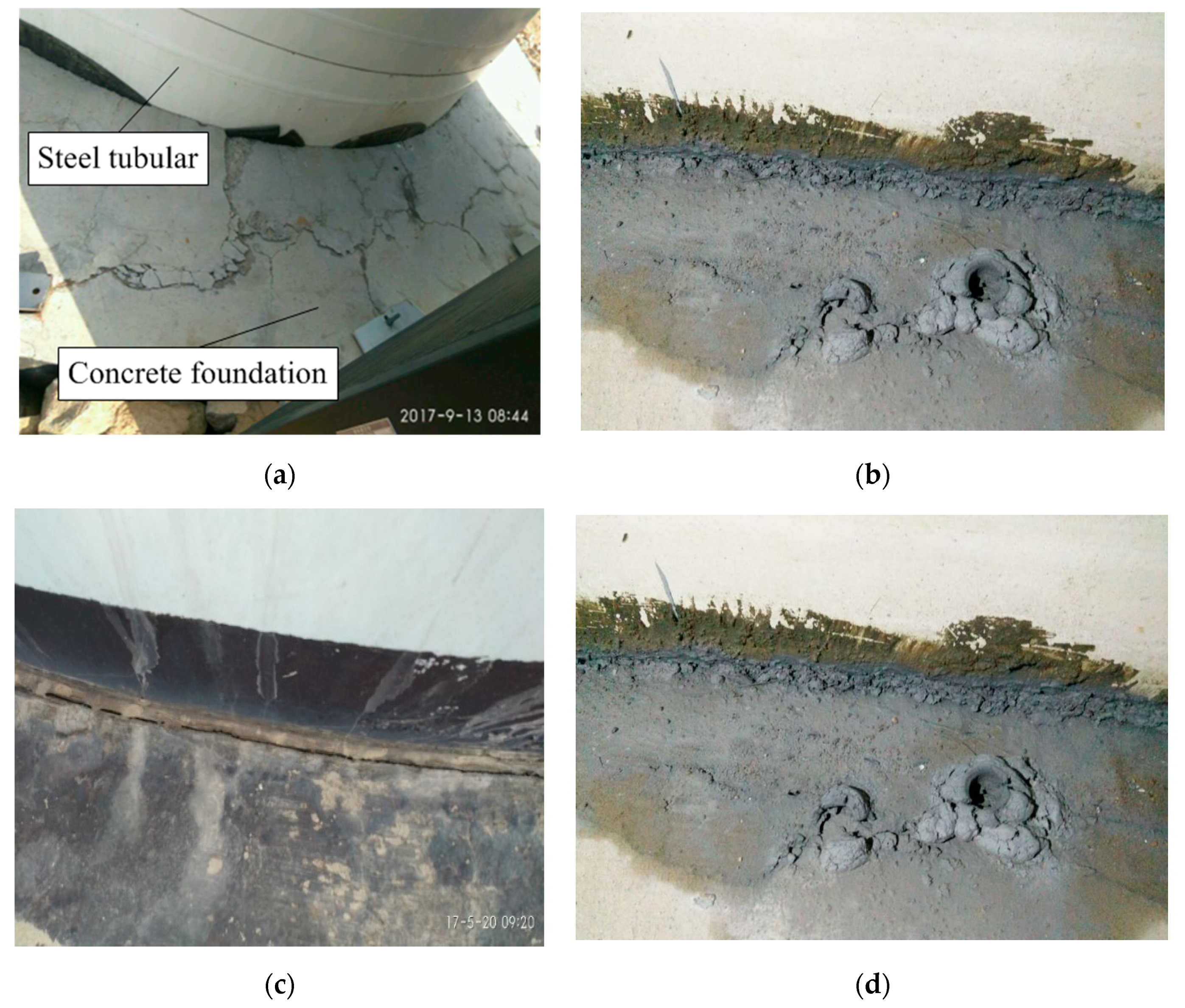
Due to climate change and the desire to preserve fossil energy resources, wind energy has received worldwide interest and wind power has become one of the fastest-growing sources of energy in the world. Wind turbines are playing a significant role in the infrastructure development of many countries and regions. The global cumulative installed wind capacity reached 539.1 GW by the end of 2017. In China, onshore wind turbines have been rapidly increasing over the past ten years as the Chinese government attempts to meet its renewable energy targets. In earlier years, the steel towers of wind turbine systems were usually connected by embedding steel rings into concrete foundation piers. However, embedded depths are usually too shallow to provide sufficient constraint stiffness for steel towers. Under the high-cycle fatigue loading induced by a wind turbine’s normal operation, higher fatigue stress occurs on the steel tower, the concrete foundation, and other structural components [1]. Therefore, different damage types have recently occurred in a large number of existing onshore concrete foundations with embedded steel rings as the connection method with the steel towers, such as surface cracks (Figure 1a), concrete leaching (Figure 1b), gaps between the steel ring and the foundation pier (Figure 1c), and cracking above the T-shaped plate of the insert ring (Figure 1d). Excluding thermal and drying shrinkage cracking during the production process or in the foundation’s early age, the damage causes of embedded-ring wind turbine foundations may have different origins such as fatigue loading, low strength concrete, unreasonable structural design, poor workmanship, structural defects, and so on [2]. The occurrence and development of damage signs in embedded-ring wind turbine foundations are often a slow process over years or even months. The interface concrete around the steel ring is constantly ground up under the dynamic loading of the wind turbine system because of the insert ring’s structural defects. Rainwater penetrates into the gaps and leads to tiny grains of concrete leaching, as shown in Figure 1b. At present, the damages in embedded-ring foundations have entered a centralized period of considerable increase in China. In some extreme cases, the gaps between embedded-ring and concrete foundations have exceeded more than 20 mm that will lead to the catastrophic collapse of turbines if the gaps and cracks cannot be handled in a timely and reasonable manner. The field investigations in some wind farms show that embedded-ring foundation damages are an urgent and widespread issue which must be taken seriously.
In recent years, some researchers have paid more attention to the common quality defects of embedded-ring foundations for wind turbine systems. Currie et al. [3] presented an assessment of embedded-ring foundation failure modes in large onshore wind turbines and proposed a novel condition-based monitoring solution to aid in the early warning of failure. Fan et al. [4] proposed a simplified fatigue analysis approach to assess the fatigue strength of the steel ring in an embedded-ring foundation according to the Chinese Classification Society specification. Kang et al. [1] analyzed the stress distribution in the foundation concrete near the steel ring and found that the gap between the steel ring and the concrete foundation increased the distinct stress, while the stress level increased with the increasing gap. Currie et al. [5] developed a wireless structural integrity monitoring technique to monitor the stability of wind turbines by measuring the displacement pattern and subsequently alerting authorities of any significant movement of the embedded ring. Huang [6] proposed a nondestructive testing technique to detect the concrete quality of the interface between the embedded ring and the foundation pier using an ultrasonic method combined with engineering practice. Bai et al. [7] presented a numerical study on the fatigue behavior of the embedded-ring foundation of onshore wind turbines. Liu and Yang [8] investigated the interaction of the steel ring and the concrete foundation by numerical simulation and found that the studs welded onto the steel ring can increase the contact between the steel ring and the foundation concrete. Lyu et al. [9] found that the strength of steel bars threaded through the holes on the wall of the steel ring could not satisfy the shear strength of the foundation and that strengthening measures should be taken in design. Fatigue failure is also a significant failure mode for offshore wind turbines. Braithwaite and Mehmanparast [10] examined the effect of the connecting bolts’ tightening sequence on preload level maintenance by three different analyses.
The retrofitting measure most commonly used in embedded-ring foundations is to drill holes on the top surface of foundation piers and pump cement slurry to fill gaps and cracks. This method can have an immediate strengthening effect, but the gaps and cracks will occur again in a short time because the force transmission mechanism between the steel embedded-ring and the concrete foundation pier is not changed. Kang et al. [1] proposed to add annular beams on the top surface of the original foundation pier to improve the compressive stress distribution between the steel embedded ring and the concrete foundation after the cracks and gaps were repaired by pumping cement slurry. The numerical results showed that this strengthening measure can effectively increase the surface strength of the foundation pier but limitedly decrease the local stress of concrete near the T-shaped plate. He et al. [11] developed a retrofitting strategy for the deficient foundation using an external prestressing technique, in which six girders were installed on the top surface of the foundation pier and prestressed anchor bolts were arranged symmetrically on both sides of the girders. The numerical results showed that the implementation of prestressing loads can reduce the width of cracks near the T-shaped plate. However, this strengthening method requires the drilling of many holes on the top surface of the concrete foundation pier, and reinforcing bars in the concrete must be cut out during the drilling process. In this study, a strengthening method by applying circumferential prestress around the original foundation pier is proposed to improve the stress state of concrete around the insert ring without destroying the original foundation. A series of numerical analyses were carried out to investigate the stress state change in the foundation concrete around the insert ring. The changes in fatigue stress amplitudes before and after strengthening were compared to show the change in fatigue life of the foundation concrete.

2. Design Concept of the Circumferential Prestressed Strengthening Method

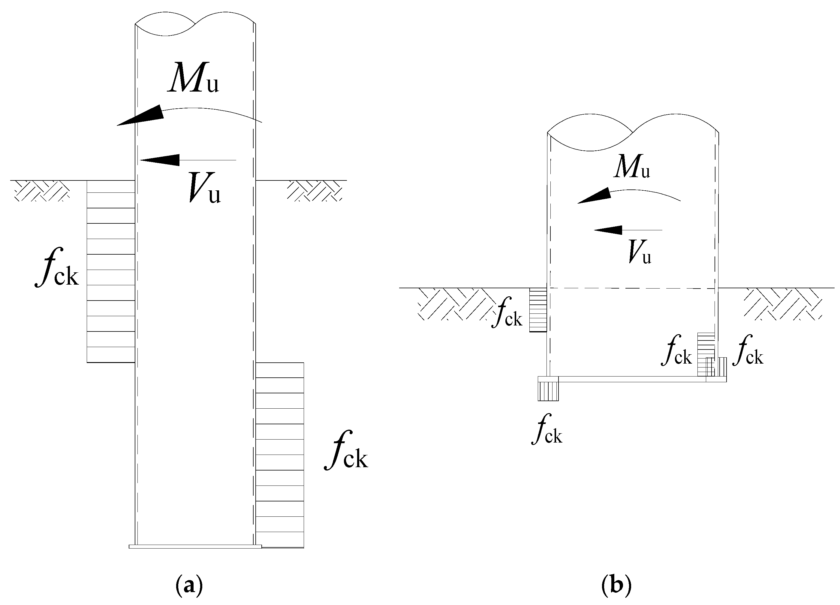
Embedded column footing is widely used in steel frame structures because of its advantages of constructive convenience and high bending stiffness, in which the overturning moment acting on the steel frame column base is mainly resisted through the lateral pressure provided by the concrete foundation contacting with the lateral sides of the steel frame column. The axial force acting on the steel column base is transferred to the foundation concrete by contacting with the base plate below. In order to ensure the transfer mechanism, as shown in Figure 2a, the depth of the tubular steel column embedded in the concrete foundation or column should not be less than 3 times its outer diameter [12]. Sufficient shear studs should be welded onto the surface of the embedded steel column to obtain an excellent binding force.
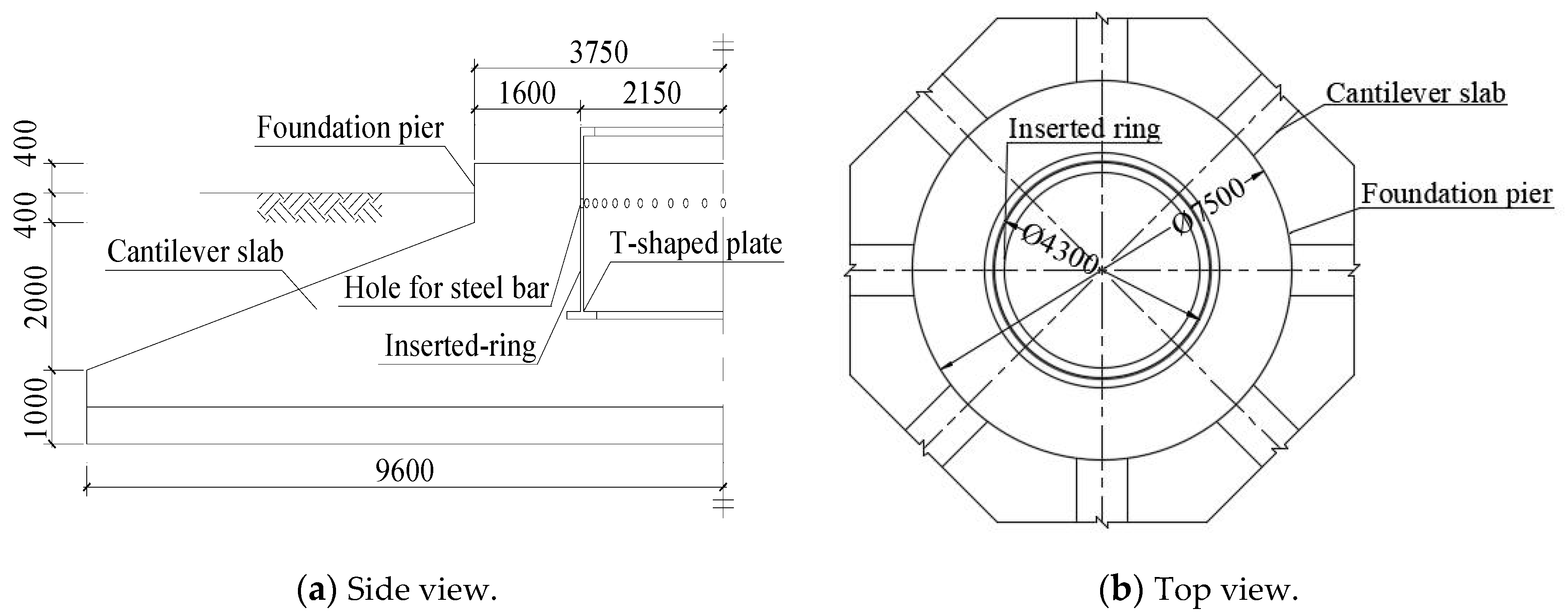
The embedded-ring wind turbine foundation, in which the steel ring connected to the bottom flange of the steel tower is embedded into the concrete foundation pier, is similar to an embedded frame column footing in appearance and structural form. However, because the relative depth of the steel ring embedded in the concrete foundation is much less than that of the steel column embedded in the concrete foundation or column, the transfer mechanisms of the ultimate bending capacity are very different between these two forms of embedded foundations. The diameter of the tubular tower base for megawatt wind turbines is generally greater than 4 m and the embedded depth of the steel ring in the wind turbine foundation is usually between 1.2 m and 2 m. Therefore, the ratio of the embedded depth to the diameter of the steel ring is lower than 0.5, which is much smaller than the requirements in JGJ99-2015 [12]. Reinforcing bars are usually threaded through the holes on the steel ring’s wall to further strengthen the connection between the steel ring and the concrete foundation. In general, no studs are welded onto the steel ring’s wall because most wind turbine companies consider that it has a negative effect on the steel ring’s fatigue strength. Therefore, the overturning moment acting on the tower base is resisted by the anchoring effect of the T-shaped plate and the lateral pressure provided by the foundation concrete contacting with the steel ring, as shown in Figure 2b.
Figure 3 shows the reinforced concrete beam-slab foundation of a wind turbine, in which the steel tower is connected to the foundation by means of an embedded steel ring. Obvious gaps and cracks occurred on the top surface of the foundation pier and the steel tower swayed noticeably after the wind turbine operated for only 20 months. During the field investigation, it was found that rainwater had permeated into the gaps and cracks between the concrete foundation and the steel ring. The flow of water around the steel ring and through the holes on its wall was induced due to the pumping effect caused by the dynamic loading and then led to the leaching of the concrete and the mortar in the transition zones between the steel ring and the concrete foundation. It was also found that there were no studs welded onto the steel ring’s wall which was connected to the concrete foundation pier only through the reinforcing bars threading through the holes. The local pressure stress of the concrete on and beneath the T-shaped plate as well as on the top edge of the steel ring was relatively large. Under alternating loads, the concrete located at the interface between the steel ring and the concrete foundation pier was ground up, resulting in gradually increasing gaps between them. After drilling holes from the top surface of the foundation pier to the area above the T-shaped plate, cracks were observed on the lateral walls of the holes using an endoscope, as shown in Figure 1d.
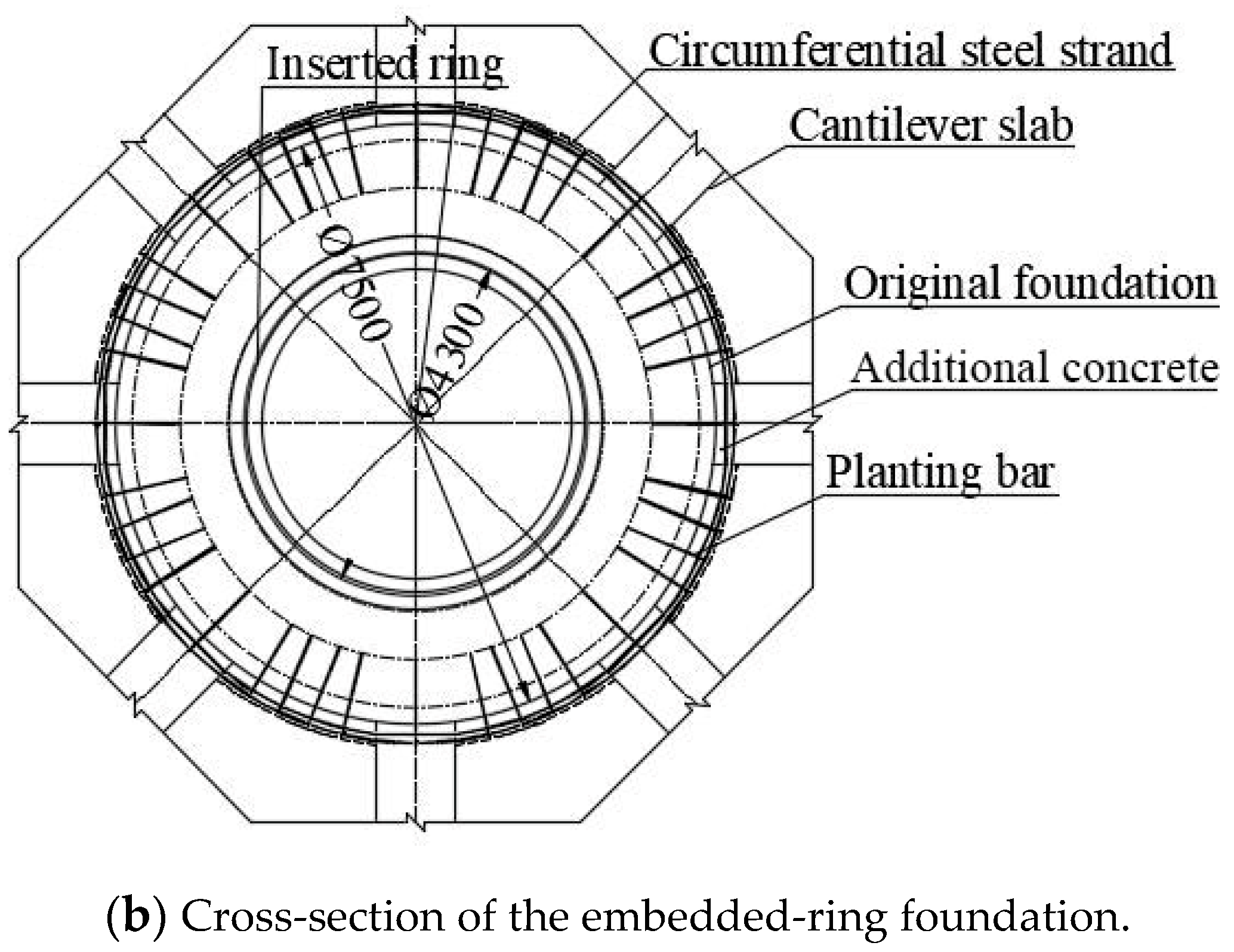
The fatigue life of concrete mainly depends on the stress level and the stress amplitude of concrete under the action of fatigue loading [13], and then it can be improved by decreasing their values. Prestressing is a mature technique of introducing a predetermined stress into the reinforced concrete structure to improve its behavior. The cracking of the concrete structure can be reduced or avoided by pre-compression, providing the ability to resist the crack-inducing tensile stresses generated by in-service loading, and then the fatigue life can be enhanced because the cyclic stress amplitude is reduced [14]. In this paper, a circumferential prestressing technique is proposed to exert on the pier of the beam-slab spread foundation. Beforehand, the gaps and cracks on the foundation pier should be filled and repaired using high strength epoxy resin with better elasticity than concrete. In order to reduce the pressure stress of the concrete on and beneath the T-shaped plate, the overturning moment resisted by the lateral pressure of the foundation pier contacting with the steel ring should be increased by increasing the embedded depth of the steel ring. Because the bolts of the bottom flange may become loose during the wind turbine’s operation, regular inspections should be carried out over the whole service life. Therefore, the concrete foundation pier is proposed to be heightened to the bottom flange of the steel tower by planting reinforcing bars as far as possible, thereby increasing the embedded depth of the steel ring in the wind turbine foundation. Finally, the circumferential prestressed steel strands are arranged on the lateral surface of the column pier to remove or reduce the tensile stress generated by external loads, as shown in Figure 4.
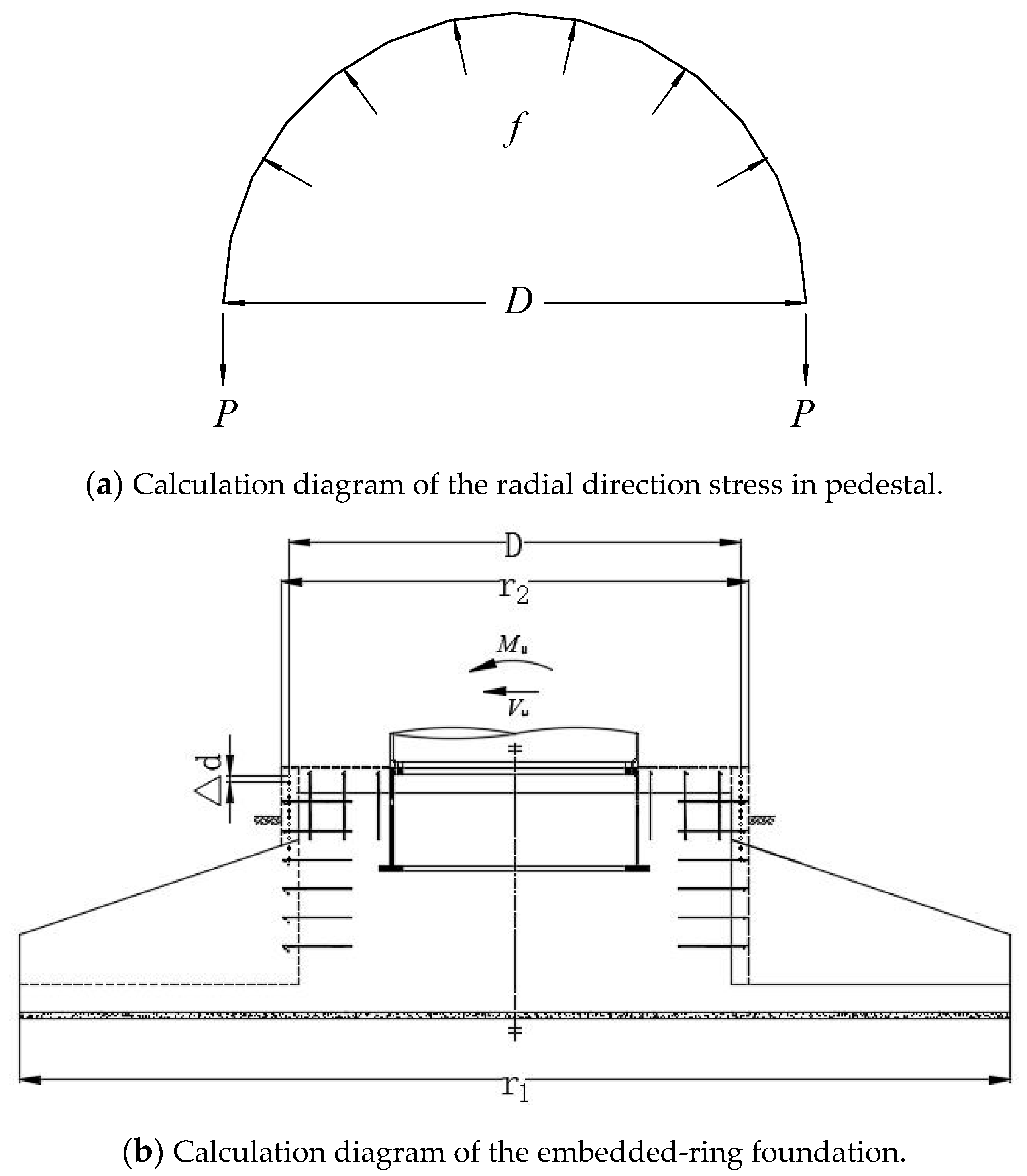
For a circular cross-section as shown in Figure 5, the radial compressive stress f generated in concrete by applying circumferential prestress can be obtained from Equation (1) according to the equilibrium condition:
f = 2 P Δ d D ,
where Δd is the spacing between steel strands, p is the value of pretension force, and D is the diameter of the circular cross-section. The edge stress in the tension zone of the foundation pier can be determined according to Equation (2) for meeting the first-level cracking control requirements in the Code for Design of Concrete Structures (GB50010-2010) [15]:
σ t k σ p c 0 ,
where σ t k is the maximum principle stress at the edge of the concrete foundation pier under the characteristic value of load combination and σ p c is the edge prepressing stress of the concrete foundation pier.
The characteristic value P1,k of gravity stress at the midpoint of the cantilever foundation slab on the windward side can be calculated according to Equation (3):
P 1 , k = G k A a c r 1 ( r 1 + r 2 ) / 2 a c P k , m a x ,
where Gk is the characteristic value of self-weight including foundation and soil, Pk,max is the characteristic value of the maximum base reaction, A is the area of the foundation slab; r1 and r2 are the radius of the circular foundation slab and the foundation pier, respectively, and ac is the width of the compression zone of the foundation slab [16].
The characteristic value of the windward-side moment in the radial direction of the foundation slab at the root of the foundation pier can be calculated by Equation (4) [17]:
M R , k = P 1 , k 3 ( r 1 + r 2 ) ( 2 r 1 3 3 r 1 2 r 2 + r 2 3 ) .
The standard value of the maximum tensile stress at the edge of equivalent section is as follows:
σ t k = M R , k I / y m a x ,
where I is the moment of inertia of the section and ymax is the distance between the neutral axis and the edge of the tension zone under bending condition.
To ensure the foundation pier under the three-dimensional pressure state, the edge prepressing stress of the concrete foundation pier σ p c is taken to be 1.2 σ t k , in which the losses of prestressing stress due to short-term relaxation, anchorage slip, elastic deformation of concrete, friction, etc., are all included. The initial prestressing force p of each strand applied to the foundation pier immediately after tensioning and anchoring should be calculated by Equation (6):
P = σ p c Δ d D 2 .

3. Numerical Analysis

3.1. Finite Element Model

The numerical simulation was carried out to investigate the strengthening effect of the circumferential prestressed technique on the embedded-ring wind turbine foundation. The three-dimensional numerical model of the beam-slab foundation (shown in Figure 3) was developed by using the general finite element analysis software ABAQUS (2018, Dassault Systemes S.A., Paris, France), as shown in Figure 6. Only half of the global model, in which the soil below the foundation base is included and the lateral soil of the foundation is neglected, was built considering that the loads, constraints, and structures were all symmetric with respect to the wind direction. The foundation concrete, the steel ring, and the ground soil were all modeled with C3D8R elements, and the reinforcing bars were represented by T3D2 elements. The radial and circular directions of the foundation pier were 54 and 24 units, respectively. Grid refinement was performed on the T-plate and the concrete of the foundation pier in contact with the T-plate. Specific numbers of component meshing are listed in Table 1. The contact surfaces between the foundation and the soil as well as between the steel ring and the foundation pier were modelled as Coulomb contact constraint. The contact surfaces both between concrete and concrete and between steel and concrete were assumed to be hard contact. The friction functions were set as penalty functions, in which the friction coefficients were set to 0.3 and 0.4, respectively. The reinforcing bars were embedded directly into the concrete. The width and the depth of the soil were, respectively, taken 4 times and 3 times the diameter of the foundation. The bottom segment of the tower with a height of 4.3 m was included in the numerical model in order to apply the external loads. The fixed constraints were applied on the bottom of the soil. A reference point was established on the center of the top circle of the tower segment, coupling its three translational degrees of freedom with those of all nodes at the top end of the tube wall in x, y, and z directions. The bending moment, torque, and vertical force under different operational cases (as shown in Table 2) were applied on the reference point.
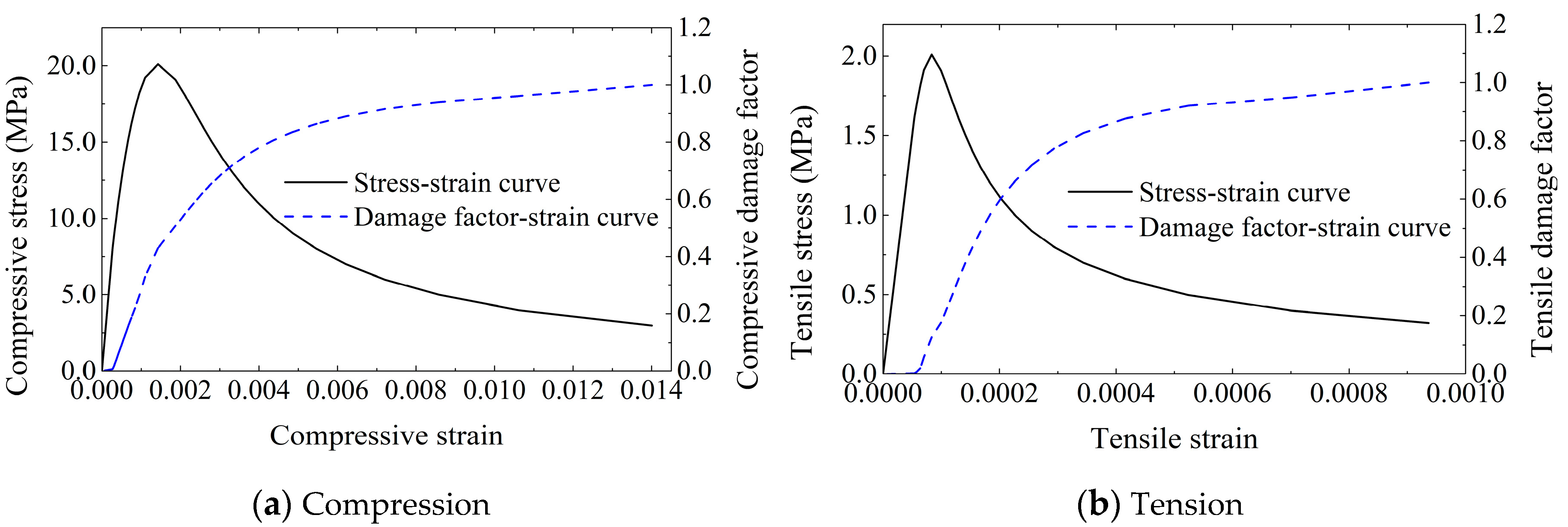
The strength grade of concrete is C30. The concrete damaged plasticity (CDP) model in ABAQUS, which was determined according to the damage plasticity model proposed in the literature [18,19], was adopted as the constitutive model, as shown in Figure 7. The differences between tensile cracking and compressive crushing of the concrete material can be considered in this model. The strength grade of reinforcing bars is HRB400. The steel ring and the tower segment were made of Q345B. The ideal elastic–plastic model was used for the reinforcing bars, the tower segment, and the steel ring. The linear elastic constitutive model was used for the soil. The physical and mechanical parameters of the concrete, steel, and soil are shown in Table 3, Table 4 and Table 5, respectively.

3.2. Numerical Results

3.2.1. Extreme Load Case

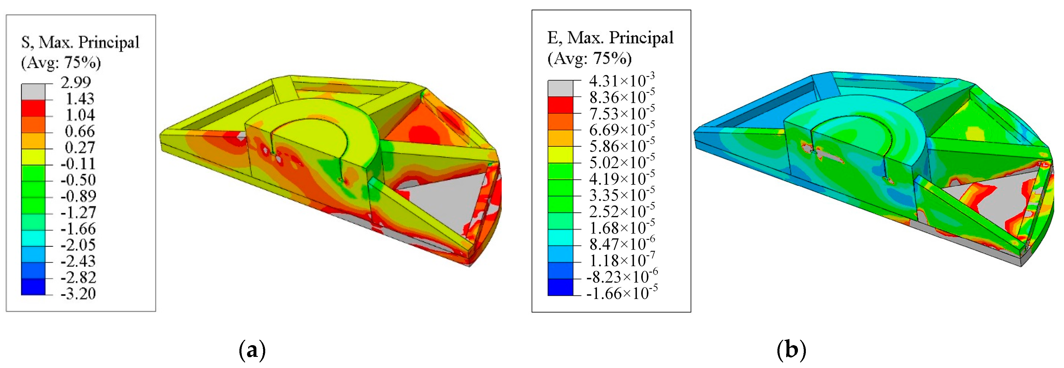
The maximum principal stress and the maximum principal strain of the foundation concrete before strengthening under the extreme load case are shown in Figure 8. From Figure 8a, it can be seen that the maximum principal stress of the windward-side concrete in the foundation pier before strengthening reached the characteristic tensile strength 2.01 MPa of concrete, which means the concrete at these zones cracked. The numerical results are consistent with the observed phenomena in the field investigation that many cracks appeared on the windward-side top surface of the foundation pier. Meanwhile, serious stress concentration phenomena occurred in the windward-side concrete on both lateral sides of the T-shaped plate, where the maximum principal stresses had not reached the characteristic tensile strength of concrete. However, from Figure 8b, it can be seen that the maximum principal strain at these local zones was greater than the cracking strain 8.36 × 10⁻⁵, which is the strain value corresponding to the peak tensile stress, as shown in Figure 8b. It should be noted that no steel bars were planted around the steel ring except the reinforcing bars passing through the holes because the foundation pier concrete was separated by the insert ring. That is to say that cracks may appear in the concrete of these zones under the extreme load case. The stiffness degradation and damage failure in concrete led to a decrease in the tensile stress. The cracking zone shows an obvious trend of expanding outward from the foundation pier. The maximum principal stress of a large zone on the leeward-side foundation slab reached the characteristic tensile strength 2.01 MPa of concrete. That is to say that the concrete in this zone may crack. The foundation slab with cracks still holds a relative high bearing capacity because of the restriction provided by reinforcing bars.
The maximum principal stress and the maximum principal strain of the foundation concrete after strengthening under the extreme load case are shown in Figure 9. From Figure 9a, it can be seen that the maximum principal stress of the windward-side concrete in the foundation pier was significantly reduced and the foundation pier was almost in the three-dimensional pressure state. Even though the tensile stresses still appeared in some local zones on the top surface of the foundation pier, their value was reduced to far below the characteristic tensile strength of concrete. However, it should be noted that the strengthening method to improve the stress concentration caused by the structural defects of the T-shaped plate was invalid. From Figure 9b, it can be seen that the maximum principal strain values of the windward-side concrete on and beneath the T-shaped plate and the leeward-side concrete outside the T-shaped plate were greater than the cracking strain 8.36 × 10⁻⁵. This means the cracks still appeared in the concrete of these zones because of the structural defects of the T-shaped plate. However, the plastic zone was significantly reduced because of the application of the circumferential prestress and the increase in the embedded depth of the steel ring. In addition, it should be noted that the leeward-side tensile stress of the foundation slab had no obvious change because the circumferential prestressing was only applied to the foundation pier. Therefore, the strengthening effectiveness of the circumferential prestressing on the foundation slab was not included in the present study.
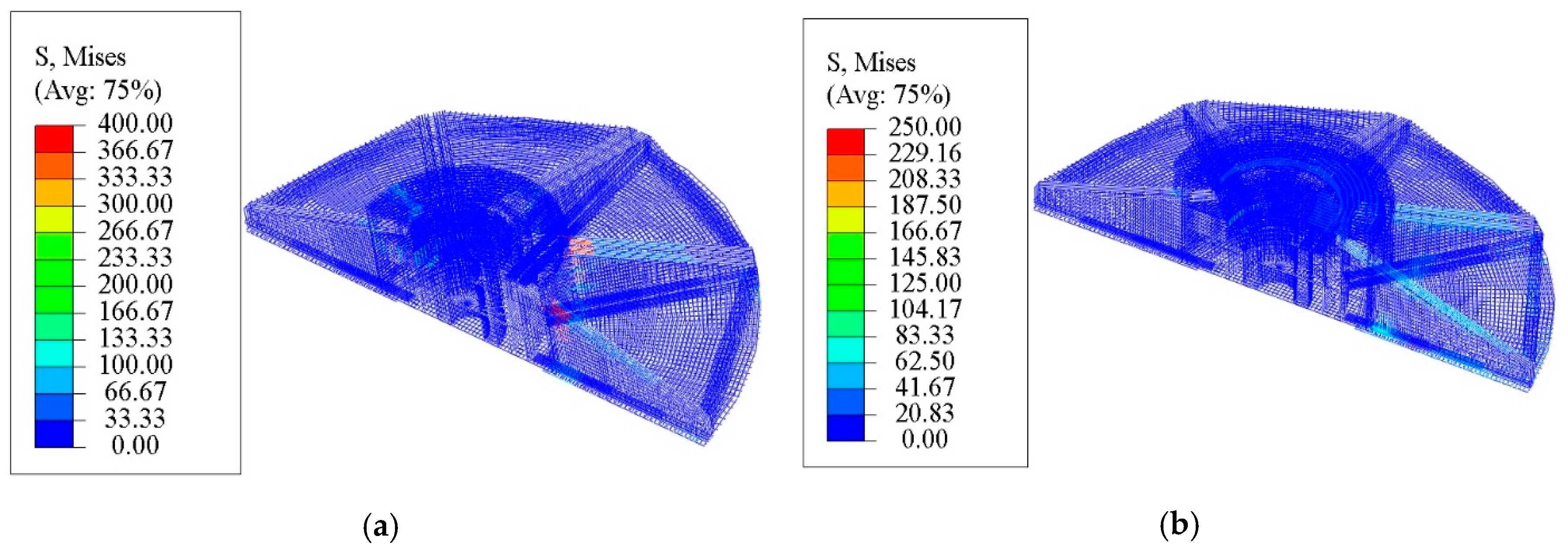
From Figure 10, it can be seen that the stress of the steel bar at the cantilevered plate on the windward side before strengthening reached 400 MPa, which means it entered a plastic phase; as a contrast, the stress of the steel bar at the cantilevered plate after strengthening was 250 MPa. The stress of reinforcement has a significant decrease of 37.5%.
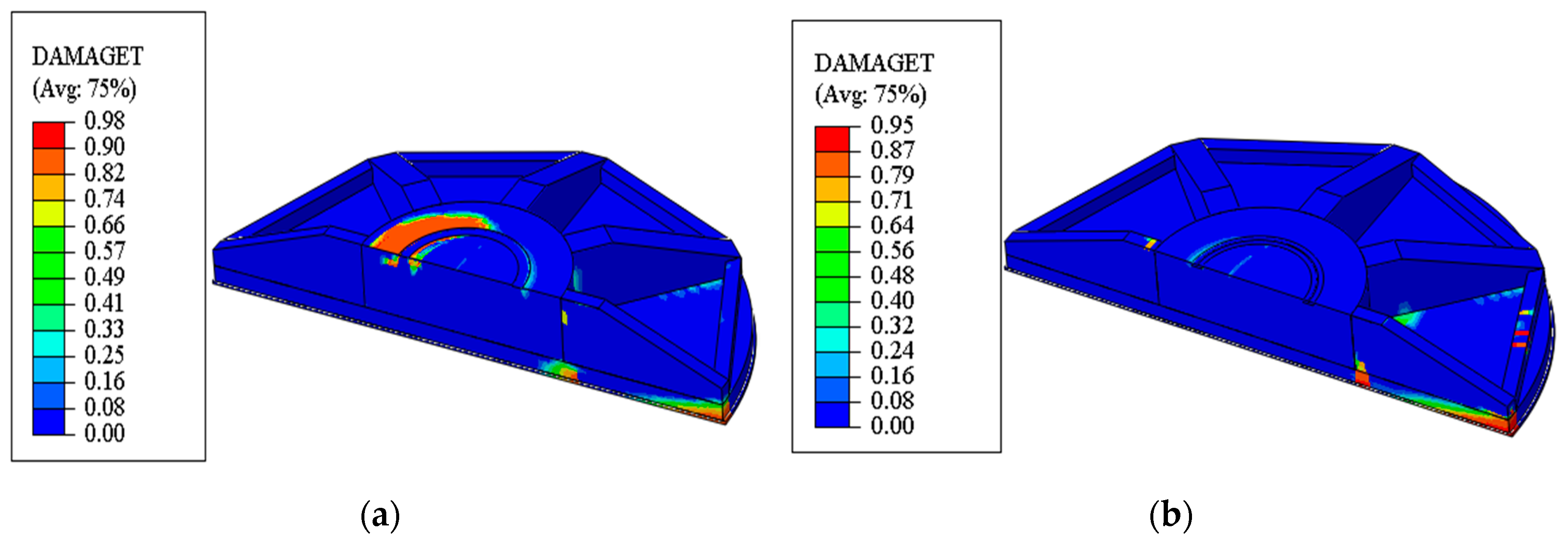
Damage refers to a deterioration of the material’s properties under monotonic or repeated loading conditions. Damage factor is used to measure the degree of material damage. The value ranges from 0 to 1, where 0 means no damage to the material and 1 means complete loss of strength. The concrete damaged plasticity (CDP) model used in the finite element analysis in this paper can simulate the damage and failure behavior of concrete under load. From Figure 11, it can be seen that the concrete on the windward-side pier before the strengthening had obvious tensile damage, and the damage of the concrete after the strengthening was significantly improved.

3.2.2. Normal Operational Case

The maximum principal stress and the maximum principal strain of the foundation concrete before and after strengthening under the normal operational case are shown in Figure 12. From Figure 12a, it can be seen that the maximum principal stress of the windward-side concrete in the foundation pier near the T-shaped plate before strengthening did not exceed the characteristic tensile strength of concrete. However, from Figure 12b, it is obvious that the maximum principal strain near the T-shaped plate was greater than the cracking strain, although the plastic zone was significantly smaller than that under the extreme load case. That is to say that cracks may appear in the concrete of these zones under the normal operational case due to the structural defects of the T-shaped flange plate. This can explain why the concrete above the T-shaped plate of the insert ring showed cracks after one or two years of operation, as shown in Figure 1d. From Figure 12c,d, it can be seen that the stress concentration phenomena still existed in the concrete around the T-shaped plate after strengthening, but the plastic zone was significantly reduced.

3.2.3. Peak Value and Valley Value of Fatigue Loading

The maximum principal stress and the minimum principal stress of the foundation concrete before and after strengthening under the peak value of fatigue loading are shown in Figure 13. From Figure 13a,c, it can be seen that the stress concentration phenomena before strengthening were most serious in the concrete around both the windward-side and leeward-side T-shaped plate due to its structural defects. From Figure 13b,d, it is clear that the minimum principal stress of the foundation pier on the windward side after strengthening changed from tension to compression, and the whole foundation pier was basically in the three-dimensional pressure state except for some local zones near the T-shaped plate. Both the tensile stress and the compressive stress of the foundation pier were lower than the characteristic compressive strength of concrete. From the comparison of the compressive stress above the T-shaped plate before and after strengthening, as shown in Figure 14a, we can see that the windward-side maximum principal stress above the T-shaped plate was evidently reduced.
The maximum and minimum principal stress of the foundation concrete before and after strengthening under the valley value of fatigue loading are shown in Figure 15. From Figure 15c,d, we can see that the maximum principal stress of the foundation pier after strengthening was significantly reduced and the minimum principal stress of the foundation pier changed from tension to compression. The whole foundation pier was in the three-dimensional pressure state and the stress concentration phenomena near the windward-side T-shaped plate were no longer apparent. The comparison of the compressive stress above the T-shaped plate before and after strengthening is shown in Figure 14b, from which it can be seen that the compressive stress of concrete above the T-shaped plate after strengthening increased approximately from 0.2 MPa to 1.2 MPa.

4. Fatigue Strength Calculation

Wind-induced fatigue is a random variable amplitude fatigue problem under the variable loading of a wind turbine system [13]. The variable amplitude load spectrum is a relatively precise method for analyzing the fatigue resistance of structural components [4]. Generally, variable amplitude loads can be obtained through two methods. One is to obtain the load spectrum with the help of existing similar structures or numerical models under various load cases; the other is to estimate the variable amplitude load spectrum according to damage theories and engineering experiences. However, the variable amplitude load spectrum is difficult to apply in practical engineering design because of its high time cost. The fatigue resistant design based on the constant amplitude load equivalently generated by the variable amplitude load spectrum is a simple, rapid, and comparatively accurate method [20,21,22]. In this paper, the fatigue analyses and verification of the embedded-ring foundation were carried out according to the equivalent fatigue damage load method.
According to the Design regulations on subgrade and foundation for wind turbine generator system (FD003-2007) [23], the fatigue strength calculation of materials for wind turbine foundation should meet the requirements of the Code for Design of Concrete Structures (GB 50010) [15]. In GB50010, the fatigue strength of steel bar and concrete are determined according to the largest acting amplitude corresponding to 2 × 10⁶ circles under randomly variable actions such as wind, waves, traffic, etc. However, the required design life of a wind turbine system is generally 20 years, during which time the number of operational load cycles to failure should be 1 × 10⁷ times. The accepted design code of wind turbine systems by manufacturers is the Guideline for the Certification of Wind Turbines compiled by Germanischer Lloyd WindEnergie GmbH [24], in which CEB-FIP (fib Model Code for Concrete Structures 2010) [25] is suggested to be applied for the fatigue verification of concrete.
The calculation of fatigue life of a concrete structure within the design life has been given by the CEB-FIB Model Code [25], where the fatigue life of concrete under equivalent fatigue load can be calculated according to the concrete stress level. This method can be used to check the fatigue strength of concrete under different equivalent cycle times. The fatigue life of the concrete outside the embedded-ring and above the T-shaped plate can be calculated by Equation (7):
f c k , f a t = β c c ( t ) β c , s u s ( t , t 0 ) f c k ( 1 f c k / 400 ) ,
where β c c is the coefficient which depends on the age of the concrete t in days when fatigue loading starts; β c , s u s ( t , t 0 ) is a coefficient which takes into account the effect of high mean stresses during loading, and for fatigue loading it may be taken as 0.8; and f c k is the standard value of concrete compressive strength.
The compressive stress level and the stress level range of concrete can be calculated by Equations (8)–(10):
S c , m a x = | σ c , m a x | / f c k , f a t ,
S c , m i n = | σ c , m i n | / f c k , f a t ,
Δ S c = | S c , m a x | | S c , m i n | ,
where σ c , m i n is the minimum compressive stress of concrete, σ c , m a x is the maximum compressive stress of concrete, S c , m a x   is the maximum compressive stress level, S c , m i n is the minimum compressive stress level, and Δ S c is the stress level range.
The number N of cycles causing fatigue failure of concrete may be estimated from Equations (11)–(14):
log N 1 = 8 ( Y 1 ) ( S c , m a x 1 ) ,
log N 2 = 8 + 8 ln ( 10 ) ( Y 1 ) ( Y S c , m i n ) log ( Δ S c Y S c , m i n ) ,
log N = { log N = log N 1 log N 1 8 log N = log N 2 log N 1 > 8 ,
Y = 0.45 + 1.8 S c , m i n 1 + 1.8 S c , m i n 0.3 S c , m i n 2 .
The fatigue requirements under cyclic loading will be met if the required lifetime (number of cycles) is less than or equal to the number of cycles to failure:
log N 7 .
The compressive stress and the fatigue strength of concrete above the windward-side T-shaped plate before and after strengthening are shown in Table 6, from which it can be seen that the compressive stress of concrete above the windward-side T-shaped plate was significantly increased under the valley value of fatigue loading and decreased under the peak value of fatigue loading. Therefore, the fatigue stress amplitude was reduced and the fatigue life of concrete above the windward-side T-shaped plate could be improved.
5. Conclusions

With respect to the traditional and widely used foundation form for wind turbine towers, severe damages have occurred in a large number of wind farms in recent years. The common damages induced by the steel ring’s structural defects, such as the stress concentration around the T-shaped plate and cracking on the top surface of the foundation pier, were verified through numerical analyses. For this paper, a circumferential prestressing technique was proposed to improve the common defects of the wind turbine foundation with an embedded-ring as the foundation–tower connection. The numerical analyses of a reinforced concrete beam-slab foundation were performed to investigate the stress and strain distribution of the foundation under different load cases. The numerical results indicate that the proposed strengthening method can effectively inhibit the development of the windward-side tensile plastic zone, although the stress concentration phenomena still existed in the concrete around the T-shaped plate after strengthening. The windward-side maximum principal stress in the concrete foundation pier was significantly reduced and the foundation pier was almost in the three-dimensional pressure state under the extreme load case. The fatigue stress amplitude of the concrete above the windward-side T-shaped plate was reduced, and its fatigue life can thus be improved after strengthening. Moreover, the circumferential prestressing technique is effective in reducing the tensile stress of concrete on the top surface of the foundation pier and improving the cracking phenomenon in that zone.

Author Contributions

Methodology, J.C.; Software, J.L.; Validation, Y.X. and J.L.; Formal Analysis, Y.X. and J.L.; Investigation, J.C.; Resources, J.C.; Data Curation, J.C.; Writing-Original Draft Preparation, J.C. and Y.X.; Writing-Review & Editing, J.C. and Y.X.; Supervision, J.C.; Project Administration, J.C.; Funding Acquisition, J.C. All authors have read and agreed to the published version of the manuscript.

Funding

This research was funded by the National Natural Science Foundation of China under Grant No. 51978528.

Conflicts of Interest

The authors declare no conflict of interest. The funders had no role in the design of the study; in the collection, analyses, or interpretation of data; in the writing of the manuscript, and in the decision to publish the results.

References

  1. Kang, M.H.; Xu, H.; Huang, X. Local damage analysis of near foundation ring in wind turbine foundation. Acta Energy Sol. Sin. 2014, 35, 583–588. [Google Scholar]
  2. Rapport, E. Cracks in Onshore Wind Power Foundations Causes and Consequences. Available online: http://www.caithnesswindfarms.co.uk/cracks.pdf (accessed on 20 January 2012).
  3. Currie, M.; Saafi, M.; Quail, F. Development of a robust structural health monitoring system for wind turbine foundations. In Proceedings of the ASME Turbo Expo 2012: Turbine Technical Conference and Exposition, Copenhagen, Denmark, 11–15 June 2012. [Google Scholar] [CrossRef]
  4. Fan, H.J.; Wang, J.F.; Jin, Q.Z.; Jin, J.K. Fatigue strength assessment of a wind turbine’s foundation-tower transitional ring. Acta Energy Sol. Sin. 2012, 33, 1123–1130. [Google Scholar]
  5. Currie, M.; Saafi, M.; Tachtatzis, C.; Quail, F. Structural integrity monitoring of onshore wind turbine concrete foundations. Renew. Energy 2015, 83, 1131–1138. [Google Scholar] [CrossRef] [Green Version]
  6. Huang, D.P. Quality detection for embedded-ring foundation of wind turbine tower using ultrasonic method. Build. Struct. 2016, 46, 8–11. [Google Scholar] [CrossRef]
  7. Bai, X.; He, M.J.; Ma, R.L.; Huang, D.P.; Chen, J.L. Modelling fatigue degradation of the compressive zone of concrete in onshore wind turbine foundations. Constr. Build. Mater. 2017, 132, 425–437. [Google Scholar] [CrossRef]
  8. Liu, M.M.; Yang, M. Interaction between foundation ring and concrete of wind turbine. Acta Energy Sol. Sin. 2017, 38, 1973–1978. [Google Scholar]
  9. Lyu, W.R.; He, X.K.; Lu, B.R.; Shi, W.H.; Zhang, J.Z.; Zhu, F.; Zhu, M.Q. Fatigue damage mechanism of wind turbine foundation with foundation pipe. J. Build. Struct. 2018, 39, 140–148. [Google Scholar] [CrossRef]
  10. Braithwaite, J.; Mehmanparast, A. Analysis of tightening sequence effects on preload behaviour of offshore wind turbine M72 bolted connections. Energies 2019, 12, 4406. [Google Scholar] [CrossRef] [Green Version]
  11. He, M.J.; Bai, X.; Ma, R.L.; Huang, D.P.; Liu, H.Q. Field experimental study on the retrofit of cracked onshore wind turbine foundations using externally prestressed anchor bolts. Struct. Concr. 2018, 19, 864–875. [Google Scholar] [CrossRef]
  12. MOHURD. JGJ99-2015, Technical Specification for Steel Structure of Tall Building; Ministry of Housing and Urban-Rural Construction of the People’s Republic of China: Beijing, China, 2015. (In Chinese)
  13. Zhao, D.F.; Chang, Q.Y.; Yang, J.H. Analysis for factors affecting fatigue behavior of concrete, Journal of Building Structures. J. Build. Struct. 2008, 29, 102–105. [Google Scholar] [CrossRef]
  14. Zhang, Y. Basic Principles of Concrete Structure, 2nd ed.; China Building Industry Press: Beijing, China, 2012. [Google Scholar]
  15. MOHURD. GB 50010-2010, Code for Design of Concrete Structures; Ministry of Housing and Urban-Rural Construction of the People’s Republic of China: Beijing, China, 2015. (In Chinese)
  16. MOHURD; The Standardization Administration of the People’s Republic of China. GB 50135-2006, Code for Design of High-Rising Structures; Shanghai Construction and Transportation Committee: Beijing, China, 2007. (In Chinese)
  17. CMCC; The Standardization Administration of the People’s Republic of China. GB 50051-2013, Code for Design of Chimneys; China Metallurgical Construction Association: Beijing, China, 2013. (In Chinese) [Google Scholar]
  18. Lubliner, J.; Oliver, J.; Oller, S.; Oñate, E. A plastic-damage model for concrete. Int. J. Solids Struct. 1989, 25, 299–326. [Google Scholar] [CrossRef]
  19. Lee, J.; Fenves, G.L. Plastic-damage model for cyclic loading of concrete structures. J. Eng. Mech. 1998, 124, 892–900. [Google Scholar] [CrossRef]
  20. Yu, Z.; Zhang, F.L.; Xiong, H.B. Fatigue reliability and remaining life analysis of prestressed concrete wind turbine towers based on linear cumulative damage rule. Eng. J. Wuhan Univ. 2016, 49, 756–762. [Google Scholar] [CrossRef]
  21. Kwon, K.; Frangopol, D.M. Bridge fatigue reliability assessment using probability density functions of equivalent stress range based on field monitoring data. Int. J. Fatigue 2010, 32, 1221–1232. [Google Scholar] [CrossRef]
  22. Sørensen, J.D.; Frandsen, S.; Tarp-Johansen, N.J. Effective turbulence models and fatigue reliability in wind farms. Probab. Eng. Mech. 2008, 23, 531–538. [Google Scholar] [CrossRef]
  23. GIWP. FD 003-2007, Design Regulations on Subgrade and Foundation for Wind Turbine Generator System; General Institute of Hydropower and Water Resource Planning and Design: Beijing, China, 2007. (In Chinese) [Google Scholar]
  24. Germanischer Lloyd. GL 2010, Guideline for the Certification of Wind Turbines; Germanisher Lloyd Industrial Services GmbH: Hamburg, Uetersen, Germany, 2010. [Google Scholar]
  25. International Federation for Structural Concrete. Fib Model Code 2013, CEB-FIP Model Code for Concrete Structures 2010; International Federation for Structural Concrete: Lausanne, Switzerland, 2013. [Google Scholar]
Figure 1. Damages of an embedded-ring foundation. (a) Surface cracks; (b) Concrete leaching; (c) Gaps; (d) Visual detection in a bore hole: cracking above the T-shaped plate.
Energies 13 00533 g001
Figure 2. Transfer mechanism of the ultimate bending capacity for an embedded foundation. (a) Steel insert column; (b) Steel insert ring.
Energies 13 00533 g002
Figure 3. Structure of an embedded-ring foundation.
Energies 13 00533 g003
Figure 4. Strengthening method of circumferential prestress.
Energies 13 00533 g004aEnergies 13 00533 g004b
Figure 5. Calculation diagram.
Energies 13 00533 g005
Figure 6. Three-dimensional numerical model.
Energies 13 00533 g006
Figure 7. Stress–strain curve and damage factor–strain curve of C30 concrete.
Energies 13 00533 g007
Figure 8. Maximum principal stress and strain of foundation concrete before strengthening under the extreme load case. (a) Maximum principal stress; (b) Maximum principal strain.
Energies 13 00533 g008
Figure 9. Maximum principal stress and strain of foundation concrete after strengthening under the extreme load case. (a) Maximum principal stress; (b) Maximum principal strain.
Energies 13 00533 g009
Figure 10. Von Mises stress of steel bar before and after strengthening under the extreme load case. (a) Von Mises stress of steel bar before strengthening (MPa); (b) Von Mises stress of steel bar after strengthening (MPa).
Energies 13 00533 g010
Figure 11. Tensile damage factor of foundation concrete before and after strengthening under the extreme load case. (a) Tensile damage factor before strengthening; (b) Tensile damage factor after strengthening.
Energies 13 00533 g011
Figure 12. Maximum principal stress and strain of the foundation concrete before and after strengthening under normal operational case. (a) Maximum principal stress before strengthening; (b) Maximum principal strain before strengthening; (c) Maximum principal stress after strengthening; (d) Maximum principal strain after strengthening.
Energies 13 00533 g012
Figure 13. Maximum and minimum principal stress of the foundation concrete before and after strengthening under the peak value of fatigue loading (MPa). (a) Maximum principal stress before strengthening; (b) Minimum principal stress before strengthening; (c) Maximum principal stress after strengthening; (d) Minimum principal stress after strengthening.
Energies 13 00533 g013
Figure 14. Comparison of windward-side compressive stress above the T-shaped plate under fatigue loading. (a) Under the peak value; (b) Under the valley value.
Energies 13 00533 g014
Figure 15. Maximum and minimum principal stress of the foundation concrete before and after strengthening under the valley value of fatigue loading (MPa). (a) Maximum principal stress before strengthening; (b) Minimum principal stress before strengthening; (c) Maximum principal stress after strengthening; (d) Minimum principal stress after strengthening.
Energies 13 00533 g015
Table 1. Element number of different components.
Component TypeElement Number
Solid ground7360
Steel bars33,278
Foundation38,808
Table 2. Forces at the tower base under different load cases.
Load ConditionsMr/(kN∙m)Mz/(kN∙m)Fr/kNFz/kN
Extreme load case66,863−3385915−3298
Normal operational case42,681751561−4124
Peak value of fatigue load24,6321553315−2993
Valley value of fatigue load2197−123143−3068
Table 3. Physical and mechanical parameters of the concrete.
Strength GradeEc/MPaμftk/MPafck/MPaρ/(kg m−3)
C3030,0000.22.0120.12500
Table 4. Physical and mechanical parameters of the steel.
Strength GradeEs/MPaμfy/MPaρ/(kg m−3)
HRB400200,0000.303607850
Q345B206,0000.303457850
Table 5. Physical and mechanical parameters of the soil.
Soil LayerEs/MPaμFsk/kPaρ/(kg m−3)
Completely weathered shale300.2200–2502092
Table 6. Fatigue verification of concrete above the windward-side T-shaped plate.
Calculation ResultsBefore StrengtheningAfter Strengthening
Compressive stress at the upper corner under the peak value of fatigue loading σc,max (MPa)6.393.89
Compressive stress at the upper corner under the valley of fatigue loading σc,min (MPa)0.211.23
Coefficient which depends on the age of the concrete t in days when fatigue loading starts βcc1.01.0
Design fatigue reference strength for concrete under compression fcd,fat (MPa)15.2715.27
Maximum compressive stress level Sc,max0.420.25
Minimum compressive stress level Sc,min0.010.08
Stress range ΔSc0.410.17
logN6.88 (less than 7)12.5
Whether or not meet the requirements of fatigue design?NoYes