Review

Tuning Techniques for Piezoelectric and Electromagnetic Vibration Energy Harvesters

Department of Engineering, Università degli Studi della Campania “Luigi Vanvitelli”, Aversa, 81031 Caserta, Italy
*
Author to whom correspondence should be addressed.
Energies 2020, 13(3), 527; https://doi.org/10.3390/en13030527
Submission received: 26 November 2019 / Revised: 10 January 2020 / Accepted: 13 January 2020 / Published: 21 January 2020
(This article belongs to the Special Issue Energy Harvesting Systems: Analysis, Design and Optimization)

Abstract

:
This paper is focused on resonant vibration energy harvesters (RVEHs). In applications involving RVEHs the maximization of the extraction of power is of fundamental importance and a very crucial aspect of such a task is represented by the optimization of the mechanical resonance frequency. Mechanical tuning techniques (MTTs) are those techniques allowing the regulation of the value of RVEHs mechanical resonance frequency in order to make it coincident with the vibration frequency. A very great number of MTTs has been proposed in the literature and this paper is aimed at reviewing, classifying and comparing the main of them. In particular, some important classification criteria and indicators are defined and are used to put in evidence the differences existing among the various MTTs and to allow the reader an easy comparison of their performance. Finally, the open issues concerning MTTs for RVEHs are identified and discussed.

1. Introduction

Vibration energy harvesters are emerging devices that are able to scavenge otherwise wasted energy from ambient vibrations [1,2]. In the last years, vibration harvesters have been proposed for a large number of applications, such as industrial applications, medical implants, embedded sensors in buildings and bridges, and regenerative shock absorbers [2,3,4,5]. In particular, in the future, vibration harvesters could be fundamental for the development of Internet of Things (IoT) applications and for Industry 4.0 revolution. In fact, IoT applications adopt wireless sensor networks made of many wireless sensor nodes (small computing devices that are able to collect and transmit data to a base station). The required energy can be delivered to the nodes of a wireless sensor network by means of vibration harvesters [6]. In this way, the nodes can become self-sufficient from the energy point of view and therefore the drawbacks of disposable batteries (environmental risks, limited reliability, need for replacement) can be strongly limited. The number of publications per year focusing on vibration energy harvesters is illustrated in Figure 1 starting from 2005. Figure 1 demonstrates the increasing scientific interest of researchers on such a topic.
The greatest majority of the proposed vibration harvesters are resonant. Therefore, this paper is focused on resonant vibration energy harvesters (RVEHs). As it will be explained in great detail in the following, the maximization of the extraction of power is of fundamental importance in practical applications involving RVEHs. In particular, the crucial aspect of such a task is represented by the optimization of the mechanical resonance frequency. In the following the term mechanical tuning technique (MTT) will be used to identify those techniques allowing the regulation of the value of the RVEH mechanical resonance frequency. A very great number of MTTs has been proposed in the literature [7,8,9,10,11,12,13,14,15,16,17,18,19,20,21,22,23,24,25,26,27,28,29,30,31,32,33,34,35,36,37,38,39,40,41,42,43,44,45,46,47,48,49,50,51,52,53,54,55,56,57]. This paper is aimed at reviewing, classifying, and comparing the main MTTs presented in the literature during the last years. In particular, some important classification criteria and indicators are defined. Such indicators can be used to put in evidence the differences existing among the various MTTs in order to allow the reader an easy comparison of their performance. In Section 2, the modeling of RVEHs and the differences between MTTs and other tuning techniques are discussed in great detail. In Section 3, important indicators for the classification of MTTs are introduced. In Section 4, an overview of the main MTTs presented in the literature is reported together with their classification on the basis of the operating principles. In Section 5, the open issues emerging from the above literature review are reported. Conclusions end the paper.

2. Piezoelectric and Electromagnetic Resonant Vibration Energy Harvesters

2.1. Modeling and Maximum Power Extraction

Resonant vibration energy harvesters (RVEHs) are devices capable of converting the mechanical energy associated to a vibration source into electrical energy. Such an energy conversion is based on a transduction mechanism that can fall in one of the following main categories: Piezoelectric [58,59,60], electromagnetic [61,62,63], electrostatic [64,65,66,67,68] (including dielectric elastomers based [67,68]), magnetostrictive [69,70,71] and triboelectric [72,73]. This paper is focused on both piezoelectric RVEHs (P-RVEHs) and electromagnetic RVEHs (E-RVEHs), since they exhibit the highest values of power densities [1,70] and they are the target of most MTTs presented in the literature. P-RVEHs are based on the piezoelectric effect that is the capability of given materials (e.g., crystals and some ceramics) to give rise to an electric voltage when subjected to a mechanical stress. In this way, they are able to lead to the conversion of mechanical energy into electrical energy. In an E-RVEH, instead, a magnetic field is produced by a vibrating magnet and an electromotive force is induced in a coil fixed to the frame. Due to vibrations, a relative displacement occurs between the magnet and the coil leading to the conversion of mechanical energy into electrical energy. The schematic models of P-RVEHs and E-RVEHs are shown in Figure 2 [74,75].
As shown in Figure 2a, in a P-RVEH a piezoelectric cantilever is clamped to a support to which vibrations are applied. The tip of the cantilever (where a mass is attached) moves out of phase with respect to the support. Therefore, there is a relative displacement xP(t) between the tip of the cantilever and the clamping point leading to the generation of electric energy. As shown in Figure 2b, in an E-RVEH a permanent magnet is connected to a spring and, due to vibrations, it moves out of phase with respect to the generator housing to which a coil is fixed. The relative displacement xE(t) taking place between the magnet and the coil gives rise to the conversion of mechanical energy into electric energy.
The devices of Figure 2 can be represented by means of the single degree of freedom (SDOF) systems represented in Figure 3 where the forces acting on the masses mP (which is a combination of the equivalent piezoelectric cantilever mass and of the tip mass [76]) and mE (oscillating magnet mass) are depicted by means of suitable arrows.
In particular, cP∙ẋP(t) and cE∙ẋE(t) are the viscous damping forces (cP and cE are the viscous damping coefficients). kP∙xP(t) and kE∙xE(t) are the elastic forces (kP is the equivalent stiffness of the piezoelectric cantilever and kE is the equivalent stiffness of the spring). θP∙vP(t) is the force due to the piezoelectric inverse effect that opposes to the strain of the piezoelectric material (θP is the piezoelectric electromechanical coupling coefficient). θE∙iE(t) is the electromagnetic force that opposes to the movement of the magnet (θE is the electromechanical coupling coefficient of the coil) [74,75].
The application of Newton’s second law, along the k ^ -axis, to such SDOF systems leads to the following equations that rule the relative displacements xP(t) and xE(t) [74,75]
m P θ P x ¨ P ( t ) + c P θ P x ˙ P ( t ) + k P θ P x P ( t ) + v P ( t ) = m P θ P y ¨ ( t )
m E θ E x ¨ E ( t ) + c E θ E x ˙ E ( t ) + k E θ E x E ( t ) + i E ( t ) = m E θ E y ¨ ( t )
where ÿ(t) is the base acceleration. Since each addend of (1) is an electric voltage, it is possible to identify for P-RVEHs the loop based equivalent electric circuit enclosed in the dashed rectangle in Figure 4a [74]. Since, instead, each addend of (2) is an electric current, it is possible to identify for E-RVEHs the node based equivalent electric circuit enclosed in the dashed rectangle in Figure 4b [75].
In Figure 4a, Cpiezo and Rpiezo, respectively are the capacitance and the resistance at the output of the piezoelectric layers. ipiezo(t) is the current generated by the piezoelectric effect whose expression is given in (3). The parallel of LL_P, RL_P, and CL_P represents a generic linear load that is connected to the P-RVEH and iP(t) and vP(t), respectively are the current and voltage across such a load. In Figure 4b, Lcoil and Rcoil, respectively are the inductance and the resistance of the harvester coil. εcoil(t) is the electromotive force induced in the coil whose expression is given in (4). The series of LL_E, RL_E, and CL_E represents a generic linear load that is connected to the E-RVEH and iE(t) and vE(t), respectively are the current and voltage across this load. It should be highlighted that the load parallel connection in Figure 4a and the load series connection in Figure 4b have been chosen, without any loss of generality, in order to get two completely dual systems.
i piezo ( t ) = θ P · x ˙ P ( t )
ε coil ( t ) = θ E · x ˙ E ( t )
If the acceleration ÿ(t) of the base vibration is sinusoidal with a frequency fvib and amplitude Avib (ÿ(t) = Avib∙cos(2πfvib∙t)), the Equations (1), (2), (3) and (4) can be written in the frequency domain and respectively become (5), (6), (7) and (8)
m P θ P [ ( 2 π f vib ) 2 X P ( f vib ) ] + c P θ P [ j 2 π f vib X P ( f vib ) ] + k P θ P X P ( f vib ) + V P ( f vib ) = m P θ P A vib
m E θ E [ ( 2 π f vib ) 2 X E ( f vib ) ] + c E θ E [ j 2 π f vib X E ( f vib ) ] + k E θ E X E ( f vib ) + I E ( f vib ) = m E θ E A vib
I piezo ( f vib ) = θ P · j 2 π f vib X P ( f vib )
E coil ( f vib ) = θ E · j 2 π f vib X E ( f vib )
where XP(fvib), VP(fvib), XE(fvib), IE(fvib), Ipiezo(fvib), and Ecoil(fvib), respectively are the Fourier transforms of xP(t), vP(t), xE(t), iE(t), ipiezo(t), and εcoil(t). j is the imaginary unit.
By analyzing the circuits of Figure 4a,b it is possible to write
I piezo ( f vib ) = V P ( f vib ) · [ G piezo + G L _ P + jB piezo ( f vib ) + jB L _ P ( f vib ) ]
E coil ( f vib ) = I E ( f vib ) · [ R coil + R L _ E + jX coil ( f vib ) + jX L _ E ( f vib ) ]
where
G piezo = 1 R piezo , G L _ P = 1 R L _ P
B piezo ( f vib ) = 2 π f vib C piezo , B L _ P ( f vib ) = 2 π f vib C L _ P 1 2 π f vib L L _ P
X coil ( f vib ) = 2 π f vib L coil ; X L _ E ( f vib ) = 2 π f vib L L _ E 1 2 π f vib C L _ E
From (7), (8), (9) and (10) the following expressions of the relative displacements XP(fvib) and XE(fvib) can be obtained
X P ( f vib ) = V P ( f vib ) · G piezo + G L _ P + j [ B piezo ( f vib ) + B L _ P ( f vib ) ] j 2 π f vib θ P
X E ( f vib ) = I E ( f vib ) · R coil + R L _ E + j [ X coil ( f vib ) + X L _ E ( f vib ) ] j 2 π f vib θ E
Therefore, by putting (14) and (15), respectively in (5) and (6), we get
V P ( f vib ) = j θ P m P A vib 2 π f vib { G piezo + G L _ P + j [ B piezo ( f vib ) + B L _ P ( f vib ) ] } [ m P ( f nat _ P 2 f vib 2 1 ) + j c P 2 π f vib ] + j θ P 2 2 π f vib
I E ( f vib ) = j θ E m E A vib 2 π f vib { R coil + R L _ E + j [ X coil ( f vib ) + X L _ E ( f vib ) ] } [ m E ( f nat _ E 2 f vib 2 1 ) + j c E 2 π f vib ] + j θ E 2 2 π f vib
Where fnat_P and fnat_E are the undamped natural frequencies of the SDOF systems shown in Figure 3.
f nat _ P = 1 2 π k P m P
f nat _ E = 1 2 π k E m E
Finally, the powers transferred from the two types of RVEHs to their loads are
P L _ P ( G L _ P , B L _ P , f vib ) = 1 2 G L _ P | V P ( f vib ) | 2
P L _ E ( R L _ E , X L _ E , f vib ) = 1 2 R L _ E | I E ( f vib ) | 2
As it is evident from (20) and (21), the powers depend on the frequency of the base acceleration and on the connected loads. Their expressions are provided in (22) and (23).
P L _ P = G L _ P ( θ P A vib 2 π f vib ) 2 2 ( f nat _ P 2 f vib 2 1 ) 2 · [ B piezo ( f vib ) + B L _ P ( f vib ) ] 2 { G piezo + G L _ P B piezo ( f vib ) + B L _ P ( f vib ) c P m P ( 2 π f vib ) ( f nat _ P 2 f vib 2 1 ) } 2 + { [ θ P 2 + c P ( G piezo + G L _ P ) m P ( 2 π f vib ) ] ( f nat _ P 2 f vib 2 1 ) [ B piezo ( f vib ) + B L _ P ( f vib ) ] + 1 } 2
P L _ E = R L _ E ( θ E A vib 2 π f vib ) 2 2 ( f nat _ E 2 f vib 2 1 ) 2 [ X coil ( f vib ) + X L _ E ( f vib ) ] 2 { R coil + R L _ E X coil ( f vib ) + X L _ E ( f vib ) c E m E ( 2 π f vib ) ( f nat _ E 2 f vib 2 1 ) } 2 + { [ θ E 2 + c E ( R coil + R L _ E ) m E ( 2 π f vib ) ] ( f nat _ E 2 f vib 2 1 ) [ X coil ( f vib ) + X L _ E ( f vib ) ] + 1 } 2
The optimal loads, that maximize the two powers PL_P(GL_P,BL_P,fvib) and PL_E(RL_E,XL_E,fvib) at a given frequency, are [77]:
B L _ Popt ( f vib ) = θ P 2 m P ( 1 f nat _ P 2 f vib 2 ) [ c P m P ( 2 π f vib ) ] 2 + [ 1 f nat _ P 2 f vib 2 ] 2 B piezo ( f vib )
X L _ Eopt ( f vib ) = θ E 2 m E ( 1 f nat _ E 2 f vib 2 ) [ c E m E ( 2 π f vib ) ] 2 + [ 1 f nat _ E 2 f vib 2 ] 2 X coil ( f vib )
G L _ Popt ( f vib ) = c P [ θ P m P ( 2 π f vib ) ] 2 [ c P m P ( 2 π f vib ) ] 2 + [ f nat _ P 2 f vib 2 1 ] 2   +   G piezo
R L _ Eopt ( f vib ) = c E [ θ E m E ( 2 π f vib ) ] 2 [ c E m E ( 2 π f vib ) ] 2 + [ f nat _ E 2 f vib 2 1 ] 2   +   R coil
The maximum powers PL_Popt(fvib) and PL_Eopt(fvib) provided to the optimal loads, at a given frequency, can be obtained by substituting expressions (24) and (26) in (22) and (25) and (27) in (23):
P L _ Popt ( f vib ) = P L _ P ( G L _ Popt , B L _ Popt , f vib ) = 1 8 · G piezo ( θ P A vib 2 π f vib ) 2 [ f nat _ P 2 f vib 2 1 ] 2 + [ c P m P ( 2 π f vib ) ] 2 + c P G piezo [ θ P m P ( 2 π f vib ) ] 2
P L _ Eopt ( f vib ) = P L _ E ( R L _ Eopt , X L _ Eopt , f vib ) = 1 8 · R coil ( θ E A vib 2 π f vib ) 2 [ f nat _ E 2 f vib 2 1 ] 2 + [ c E m E ( 2 π f vib ) ] 2 + c E R coil [ θ E m E ( 2 π f vib ) ] 2
In Figure 5, the typical trend that is exhibited by the maximum load powers of a P-RVEH and of an E-RVEH vs. the vibration frequency (fvib) is reported. The unique symbol PLopt is used in Figure 5 for the maximum load power of both types of RVEHs.
It is clear that, due to the resonant nature of RVEHs, the global maximum power (the peak power Pmax in Figure 5) is provided to the optimal loads only when the vibration frequency is equal to the frequencies fPopt and fEopt (a unique symbol fopt is used in Figure 5). By differentiating (28) and (29) with respect to fvib and by equating to zero the obtained expressions it is possible to find the values of the frequencies fPopt and fEopt.
f Popt = f nat _ P = 1 2 π k P m P
f Eopt = f nat _ E = 1 2 π k E m E
As shown in (30) and (31), fPopt and fEopt are coincident with the undamped natural frequencies of the SDOF RVEHs’ models and are typically also called mechanical resonance frequencies. It is worth noting here that, by observing the equivalent circuits of Figure 4, the above mechanical resonance frequencies can be obtained by means of suitable frequency scans of proper electrical quantities at the output of the RVEHs. In particular, in the case of P-RVEHs, the fPopt is equal to the resonance frequency of the short circuit current. Instead, in the case of E-RVEHs, fEopt is equal to the resonance frequency of the open circuit voltage.
The expressions of the global maximum powers provided by the RVEHs in correspondence of their mechanical resonance frequencies are reported in (32) and (33).
P L _ Pmax = P L _ Popt ( f Popt ) = 1 8 ( θ P m P A vib ) 2 G piezo · c P 2 + c P · θ P 2
P L _ Emax = P L _ Eopt ( f Eopt ) = 1 8 ( θ E m E A vib ) 2 R coil · c E 2 + c E · θ E 2
It is worth highlighting that, in correspondence of the mechanical resonance frequencies fPopt and fEopt of the RVEHs, the optimal loads assume simplified expressions:
B L _ Popt ( f Popt ) = B piezo ( f Popt )
X L _ Eopt ( f Eopt ) = X coil ( f Eopt )
G P _ Lopt ( f Popt ) = θ P 2 c P   +   G piezo
R E _ Lopt ( f Eopt ) = θ E 2 c E   +   R coil

2.2. Definition of Tuning Techniques

Due to their resonant nature, RVEHs are able to efficiently operate only when the vibrations’ frequency is equal to their mechanical resonance frequency (see Figure 5). This means that, once a given RVEH has been factory tuned to a predefined mechanical resonance frequency (fopt), it has to be used only in those applications that are characterized by a dominant frequency (fvib) that is coincident with such a mechanical resonance frequency. During the last years, some papers have been proposed in the scientific literature on the optimal design of RVEHs based on the characteristics of the vibrations [78,79,80]. As an example, cantilever beam shape optimization has been studied in great detail in case of P-RVEHs [81,82,83]. Unfortunately, in most practical cases, the frequencies of the exploitable sinusoidal vibrations are time-varying or even such vibrations are not sinusoidal but are characterized by a random behavior with a wide frequency spectrum where the energy is distributed [84,85,86]. Therefore, in practical applications, the increase of the effective operating frequency range of RVEHs is mandatory. In the literature, a number of papers describing control methods or architectures that are specifically designed with the aim of increasing the effective operating frequency range of RVEHs, has been proposed [87,88,89,90,91,92,93,94,95]. In particular, harvesters arrays, nonlinear harvesters, and mechanical tuning techniques (MTTs) are the most widely analyzed optimization methods. There is general agreement on the fact that MTTs are much more promising with respect to the other two options. This is essentially due to the low volumetric power density of harvesters arrays and to the considerable complexity of nonlinear harvesters [95].
MTTs of RVEHs are essentially based on the proper regulation of their mechanical resonance frequency in order to make it (theoretically) always coincident with the vibration frequency (the objective is to obtain fopt = fvib in all the operating conditions). Obviously, as it is evident from the previous Modeling Section, another requirement is mandatory for maximizing the extraction of power from RVEHs. In fact, even if the mechanical resonance frequency of a RVEH is always coincident with the vibration frequency, the extracted power is dependent on the RVEH load impedance. In particular, according to Section 2.1 (see Equations from (24) to (27) and from (34) to (37)) and on the basis of the maximum power transfer theorem [77], the optimal load impedance of a RVEH, that is the load impedance able to maximize power drawn from the RVEH itself, changes with fvib. Therefore, a second objective to fulfill is the matching of the RVEH with its optimal load impedance, frequency by frequency. This is the aim of the so-called electrical tuning techniques (ETTs) [96,97,98,99,100,101,102]. It is worth noting that the application of the ETTs of course does not change the mechanical resonance frequency of a RVEH. ETTs allow the maximization of the extraction of power at each frequency; but the vibration frequency that allows to obtain the global maximum power (PMAX) always is the mechanical resonance frequency. The only way to change such a frequency is by means of a MTT. In order to better clarify such a statement, it is useful to analyze the following figures.
In Figure 6a the application of ETTs is explained. In particular, each color curve represents the frequency scan of the power PL(RLopt(fk),XLopt(fk),fvib) provided to the fixed load (RLopt(fk),XLopt(fk)) (k = 1, 2,… n). Each color curve PL(RLopt(fk),XLopt(fk),fvib) has been obtained in correspondence of a different fixed load (RLopt(fk),XLopt(fk)) that is just the optimal load in correspondence of the frequency fk (see Equations from (24) to (27)). Therefore, each color curve is maximized only when fvib = fk. The envelope of the maximums PETT(fvib) ≡ PLopt(fvib) ≡ PL(RLopt(fvib),XLopt(fvib),fvib) of the color curves (dashed black curve in Figure 6a) represents the maximum power, as a function of the frequency, that can be gotten with the application of the ETT. It is clear that the frequency that allows to obtain the maximum global harvesting of power is unique and coincident with the mechanical resonance frequency fopt. In conclusion, ETTs allow only the maximization of the extraction of power at a given vibration frequency fvib from a given RVEH with a fixed mechanical resonance frequency fopt. ETTs do not change the mechanical resonance frequency of the RVEH. As stated above, the only way to change such a frequency is by means of a MTT. In other words, the black dashed curve PETT(fvib) of Figure 6a indicates the best performance that can be obtained with the application of only ETT without MTT.
In Figure 6b the application of MTT is explained. In particular, the color curves have been obtained by using a fixed load that is without adopting any ETT. Such a fixed load is the optimal load (given by Equations from (34) to (37)) in correspondence of the RVEH untuned mechanical resonance frequency fopt (gray curve). What changes among the color curves is the mechanical resonance frequency fopt_k (k = 1, 2,…n). In other words, the color curves represent a sort of horizontal translation, at different resonance frequencies, of the central grey curve of Figure 6b that coincides with the central gray curve of Figure 6a. The envelope of the maximums of such color curves (dashed black curve in Figure 6b) represents the maximum power PMTT(fvib) ≡ PL(RLopt(fopt),XLopt(fopt),fvib) that can be harvested, as a function of the frequency, by applying MTT without ETT. It is clear that, in this case, the performance of the RVEH is improved, with respect to the case of Figure 6a, because the mechanical characteristics of RVEH are changed and therefore it always resonates in correspondence of the vibration frequency fvib. However, by observing the dashed black curve in Figure 6b, it is evident that there is still an optimal frequency. It is the untuned resonance frequency fopt. This happens because a fixed load has been considered and such a load is just the optimal one at fopt. This aspect can be clarified by observing that the optimal load at fopt (see Equations from (34) to (37)) has a resistive part that is independent from the resonance frequency and hence it does not need a regulation while applying MTT. Instead, the reactive part of the optimal load at fopt, that compensates the reactive part of the output impedance of the considered RVEH (Cpiezo for P-RVEH and Lcoil for E-RVEH), depends on the frequency and hence it would need a regulation while applying MTT. Therefore, a fixed not optimized load, leads to the nonhorizontal shape of the maximum extracted power PMTT(fvib) (black dashed curve in Figure 6b).
Taking into account the previous considerations it is clear that, in general, for the optimal exploitation of a RVEH it is necessary to apply jointly both a MTT and an ETT at the same time as shown in Figure 6c. In this case, as desired, the perfect horizontal translation of the maximum extractable power curve is obtained. In other words, the color curves in Figure 6c represent perfect horizontal translations, at different resonance frequencies, of the black dashed curve of Figure 6a. The envelope of the maximums of such color curves (dashed black curve in Figure 6c) represents the maximum power PMTT-ETT(fvib) ≡ Pmax ≡ PL(RLopt(fvib),XLopt(fvib),fvib) that can be extracted, frequency by frequency, with the joint application of both a MTT and an ETT.
Summarizing, the application of an ETT without any MTT leads to the extraction of the power PETT(fvib) represented by the black dashed curve in Figure 6a. The application of a MTT without any ETT leads to the extraction of the power PMTT(fvib) represented by the black dashed curve in Figure 6b. The joint application of both an ETT and a MTT leads to the extraction of the power PMTT-ETT(fvib) represented by the black dashed curve in Figure 6c.
This paper is focused on MTTs. The aim is to review, to classify, and to compare the main ones presented in the literature during the last years.

3. Indicators for the Classification and Comparison of Mechanical Tuning Techniques

As stated in the previous Section, MTTs of RVEHs are based on the proper regulation of their mechanical resonance frequency in order to make it (theoretically) always coincident with the vibration frequency. MTTs have been implemented in various ways [7,8,9,10,11,12,13,14,15,16,17,18,19,20,21,22,23,24,25,26,27,28,29,30,31,32,33,34,35,36,37,38,39,40,41,42,43,44,45,46,47,48,49,50,51,52,53,54,55,56,57]. Basically, all the MTTs are based on the fact that RVEHs can be schematically represented (as discussed in Section 2.1) by means of spring-mass-damper systems. The mechanical resonance frequency of such systems (see (30) and (31)) depends on the values of the mass and of the stiffness and therefore it can be varied by acting on such two parameters values. In particular, for obvious reasons, during the RVEH operation it is easier to apply a MTT by varying the stiffness rather than by varying the value of the oscillating mass. In fact, to the best of the authors’ knowledge, nearly all the MTTs are based just on the regulation of the stiffness. In Table 1, a description of the operating principles of the main types of MTTs that have been proposed in the literature is reported.
In the following, a number of indicators that will be used for the classification and comparison of MTTs, will be introduced and described.
  • Indicator Name: RVEH.
  • Description: It indicates the type of RVEH to which the considered MTT is applied. If RVEH is “P” (“E”) it means that the considered MTT is applied to a P-RVEH (an E-RVEH). RVEH can be also equal to “Hybrid P/E” if the considered MTT is applied to a hybrid piezoelectric–electromagnetic RVEH.
  • Indicator Name: Direction.
  • Description: It indicates the oriented direction that, starting from the untuned resonance frequency, a MTT is able to exploit. In particular, if direction is “BOTH” the MTT is able to move the mechanical resonance frequency both in the increasing and in the decreasing direction. If instead direction is “RIGHT” (“LEFT”) the MTT is able to move the mechanical resonance frequency only in the increasing (decreasing) direction.
  • Indicators Name: ΔfR and ΔfL.
  • Description: These percentage indicators provide information concerning the range of frequency where the MTT can be applied with respect to the untuned mechanical resonance frequency. They are defined as follows
    Δ f R = f R f opt f opt · 100 %
    Δ f L = f opt f L f opt · 100 %
    where fR (fL) is the maximum (minimum) achievable frequency in the right (left) direction starting from the untuned mechanical resonance frequency fopt. The definition of both indicators is obviously possible only for MTTs that can exploit both directions of tuning.
  • Indicators Name: ΔPR and ΔPL.
  • Description: These percentage indicators provide information concerning the reduction of the extracted power that is obtained at fR and fL with respect to fopt. They are defined as follows:
    Δ P R = P R P MAX P MAX · 100 %
    Δ P L = P L   P MAX P MAX · 100 %
    where PR (PL) is the maximum extractable power in correspondence of fR (fL). Moreover, in this case, the definition of both indicators is obviously possible only for MTTs that can exploit both directions of tuning. Of course, in order to be able to compare MTTs, it is fair to provide also the amplitude Avib of the input acceleration.
  • Indicator Name: Implementation.
  • Description: It describes the way the considered MTT is implemented. In fact, the mechanical resonance frequency of an RVEH can be varied by acting on many different variables. Some of these are mechanical quantities, other are electrical quantities. Therefore, implementation can be “MECHANICAL” for mechanically implemented MTTs or “ELECTRICAL” for electrically implemented MTTs. In particular, in a mechanically implemented MTT the working principle of the tuning relies on the regulation of a mechanical variable (as an example a distance between magnets or the position of a clamp) even if such a variable is tuned by means of an electrical system (as an example an electrical actuator). What is important in this definition is the fundamental variable driving the working principle and not its particular implementation. Instead, in an electrically implemented MTT the operating principle of the tuning is based on the regulation of an electrical quantity (as an example the voltage of a piezoelectric actuator).
  • Indicator Name: Actuation.
  • Description: It indicates the way the considered MTT is actuated. In particular, if actuation is “MANUAL” the MTT needs the intervention of an operator that manually acts on the tuning mechanism. Instead, if it is “AUTOMATIC” the MTT adopts an actuator (as an example a motor) or an electrical signal in order to prevent the human intervention.
  • Indicator Name: Control.
  • Description: If control is equal to “OPEN LOOP” then the MTT needs a precharacterization of the RVEH (e.g., for the definition of a look-up table) and it is affected by errors due to any possible parameter change in the system. If control is equal to “CLOSED LOOP” then the MTT is more robust and does not need a precharacterization, but it needs sensors in order to implement the feedback circuitry and hence more energy is required for its operation. Obviously, the only type of actuation that can be controlled in a closed loop is the AUTOMATIC one.
  • Indicator Name: Supply.
  • Description: It provides a picture of the type of power demand characterizing the considered MTT. In particular, if supply is “PASSIVE”, the considered MTT needs a significant amount of power only to move the RVEH’s resonance frequency but it is able to indefinitely maintain the new resonance frequency value without any additional power consumption. In such a case, the control system energy consumption mainly depends on the energy required for the tuning step and, hence, on the rate of resonance frequency adjustments that the operating conditions require. If instead supply is “ACTIVE”, besides the initial power required in order to move the resonance frequency, the MTT continues to require power in order to maintain the new resonance frequency. If supply is “SEMI-ACTIVE”, the MTT needs an initial significant amount of power for moving the resonance frequency and it is able to maintain, only for a limited period of time, such a new value of resonance frequency without any other additional power demand. However, due to unavoidable continuous drifts of the resonance frequency, a periodic refresh is needed with additional power demands. It is worth noting that, the supply indicator can be defined only when the actuation indicator is equal to AUTOMATIC (without human intervention).
  • Indicator Name: Tuning period.
  • Description: This is a crucial indicator when considering the power consumption. The main requirement for a MTT is of course as low as possible power consumption. A MTT that consumes an average power greater than the harvested one is obviously useless in practice. In fact, the main purpose of a RVEH is to power both the MTT controller and the load in any vibrations’ conditions. The tuning period indicator provides the minimum period of time that is needed by the REVEH in order to store the amount of energy needed by the MTT controller for a given resonance frequency adjustment in the considered acceleration conditions. Obviously, in the presence of vibration frequency shifts, for a proper operation of a MTT the tuning period must be much shorter than the period of the vibration’s frequency shifts. The shorter the tuning period is, the faster the MTT will be able to react to vibrations’ frequencies changes. There are papers in which this aspect is not discussed at all. The tuning period indicator can be defined only when the actuation indicator is equal to AUTOMATIC.
  • Indicator Name: Vibrations.
  • Description: This indicator is focused on the type of vibrations that the considered MTT and the corresponding RVEH are able to exploit. In particular, the basic classification that is considered in this paper is between “SINUSOIDAL” and “NOT-SINUSOIDAL” vibrations. This is a crucial aspect from the practical point of view. Various vibration sources characterized by different harmonic contents exist in practical applications. Examples of vibration sources are walking people, moving trains or cars, and domestic or industrial working machines [84,85,86]. Sinusoidal vibrations are rarely encountered in real world applications. Even if vibrations in practical applications are usually periodic, random, or single event motions (e.g., impacts) [84,85,86], for simplicity reasons, most research papers focusing on RVEHs and in particular on MTTs deal with purely sinusoidal vibration sources.
In the following, the proposed indicators will be assigned to all the MTTs that are reported in Table 1. This is crucial in order to carry out a fair comparison among the MTTs that have been proposed in the literature.

4. Overview of Mechanical Tuning Techniques

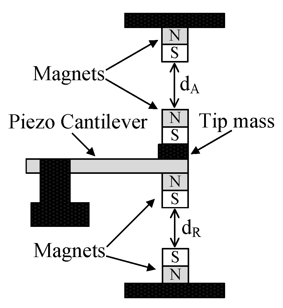
4.1. Magnetic Forces Based MTTs

Magnetic forces based MTTs rely on the interaction among magnets with the aim of altering the stiffness of a RVEH, thus changing its mechanical resonance frequency [7,8,9,10,11,12,13,14,15,16,17,18,19,20]. Usually two magnets are used, one is part of the oscillating mass and the other is movable. The displacement of the movable magnet can be obtained by means of a human operator, in the case of manual MTTs, or by means of an actuator, in the case of automatic techniques. The force exerted by the movable magnet on the oscillating one varies as a function of their distance and is used in order to tune the resonance frequency. Obviously the two magnets can be placed so that their forces are attractive or repulsive. It is clear that, by definition, this type of MTT is mechanically implemented because it basically acts on a mechanical quantity that is the distance between the magnets. Moreover, it can be applied to both P-RVEHs and E-RVEHs. To the best of the authors’ knowledge, this type of MTT is the most exploited and discussed in the literature of the last years. However, it is important to underline that, at the moment, there is not a way to theoretically predict the resonance frequency obtained as a function of the distance of the magnets. In fact, there is always the need of an experimental precharacterization of the system in order to be able to estimate the obtainable resonance frequency. In the following, the main magnetic forces based MTTs are discussed [7,8,9,10,11,12,13]. Additional magnetic forces based MTTs [14,15,16,17,18,19,20] are reported in the Reference Section without a specific description since their working principles are very similar to the ones described in this Section.
The first MTT based on a magnetic force was presented in 2008 by Challa et al. [7]. The considered device, as schematically shown in Figure 7, is composed of a piezoelectric cantilever beam with a tungsten mass placed at its free end and four permanent magnets used for resonance frequency tuning. Experimental results are provided in [7], in which the distance between the magnets is manually changed. Moreover, the authors provide also a simple calculation for the estimation of the amount of energy required to tune the device if a mechanical actuator would be used. They estimate a tuning period of about 320 s.
In [8,9], this type of MTT is applied to a MEMS-scale E-RVEH. As shown in Figure 8, the electromagnetic harvesting mechanism is obtained by positioning a spring-supported magnet (harvesting magnet) above a coil. A second magnet (tuning magnet) is placed at an appropriate height from the harvesting one so that a repulsive force takes place between the harvesting and tuning magnets. The distance between the tuning and harvesting magnets is manually adjusted by means of a screw mechanism.
In [10], the above tuning technique is further developed and extended on the basis of a more advanced magnetic forces control, by moving the magnets in a two-dimensional (2D) space (Figure 9). In fact, a P-RVEH based on a two layers cantilever beam architecture is used and a vibrating magnet is attached to its tip mass. In order to obtain the mechanical tuning a second magnet moves in a 2D space: Both the vertical and the horizontal positions of the tuning magnet can be varied. These variations are carried out manually by means of two tuning screws, one for the vertical and the other one for the horizontal directions. Unfortunately, in [10] nothing is said about the power extracted by the P-RVEH but the MTT is tested with the harvester working only in open circuit conditions.
In [11], the concern is instead on the development of a self-tuning E-RVEH jointly adopting frequency detection and self-actuation. In particular, [11] proposes an E-RVEH that is designed to adjust in an automatic way its own resonance frequency to match that one of the base excitation. Resonance frequency tuning is obtained by means of permanent magnets inducing tensile forces on the resonator (Figure 10). Frequency sensing relies on the adoption of a microcontroller together with an electromagnetic sensor. The information about the vibration frequency is used to give instructions for driving a linear actuator in order to tune the resonance frequency in an open-loop control algorithm based on a look-up table (LUT). The tuning period of the proposed device is estimated to be 217 s. This is the time required by the E-RVEH in order to collect enough energy for re-adjusting its resonance frequency. Of course, in order to produce a power greater than that consumed for the tuning mechanism, longer periods must be used.
Moreover, in [12,13], a self-tuning control system is developed to automatically adjust the resonance frequency of an E-RVEH. In particular in [12,13], a closed-loop frequency tuning system based on the use a microcontroller is developed. It periodically senses the output voltage of the E-RVEH and drives a linear actuator adjusting the distance between two tuning magnets (the first magnet is attached to the free end of a cantilever while the second one is placed on an actuator axially in line with the cantilever). When the output voltage reaches its maximum (this MTT is based on the hypothesis of fixed load resistance), the microcontroller realizes that the E-RVEH is operating at the resonance and stops the tuning mechanism. At this point, the microcontroller enters in sleep mode in order to save power. It wakes up every tuning period to monitor the output voltage and take a decision. The tuning period is estimated to be equal to about 230 s.
A summary of the described magnetic forces based MTTs is reported in Table 2.

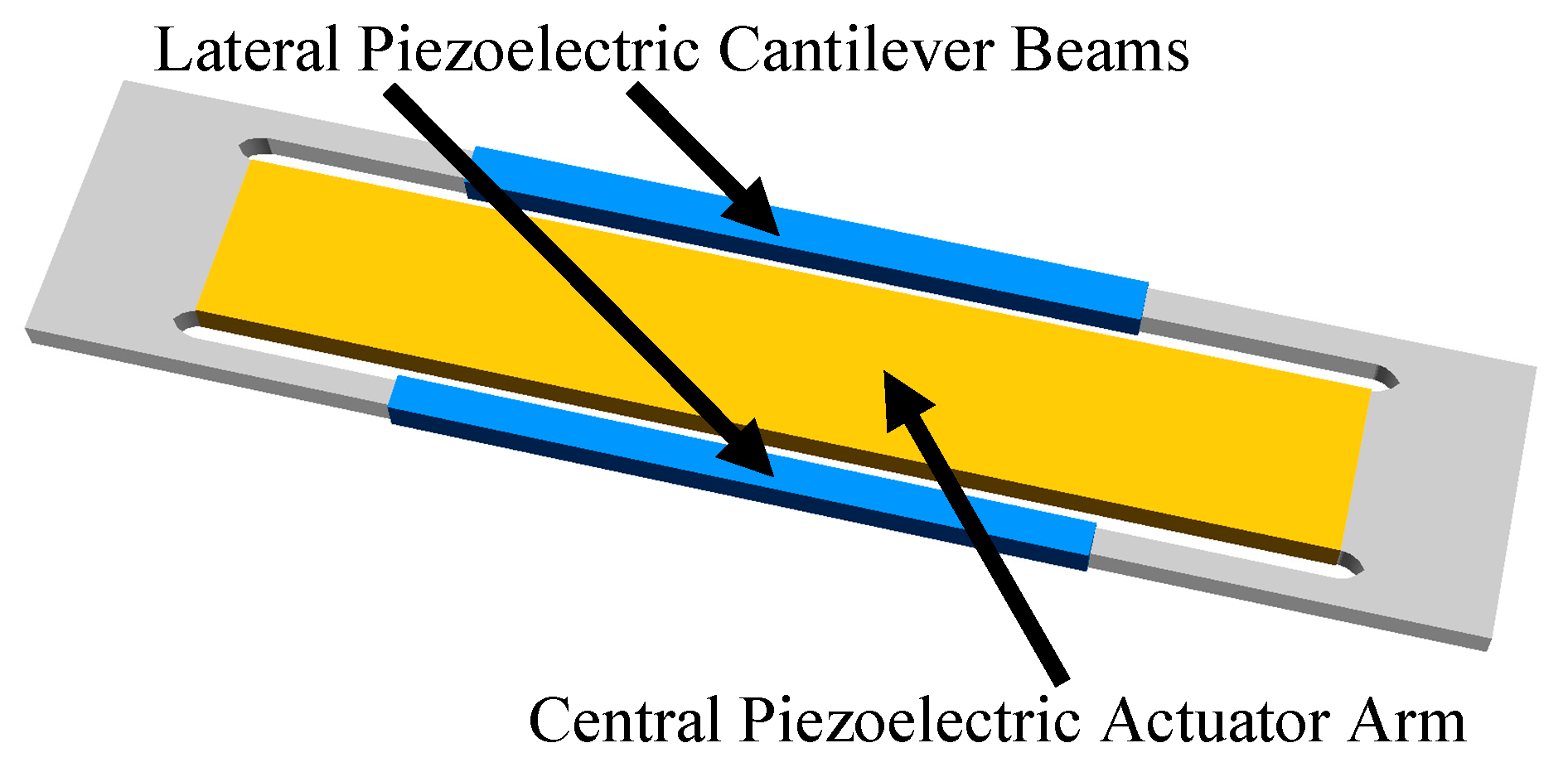
4.2. Piezoelectric Actuators Based MTTs

In piezoelectric actuators based MTTs, the tuning of the resonance frequency is implemented by changing the mechanical stiffness by using piezoelectric actuators [21,22,23,24,25,26,27,28,29]. In other words, by applying an appropriate voltage to a piezoelectric actuator it is possible to alter the mechanical stiffness of the elastic support of the RVEH. In fact, piezoelectric materials can be used to make devices acting either as energy harvesters or as actuators acting as mechanical supports with variable stiffness. Piezoelectric actuation has the advantage of not requiring the displacement of magnets, as it happens with magnetic forces based MTTs, or clamping or other devices as it happens with other MTTs described in the following Sections. The implementation of the MTT is simply obtained by means of a voltage applied to the considered piezoelectric material. This means that piezoelectric actuators based MTTs are electrically implemented. Moreover, piezoelectric actuators offer a fast reaction, are able to give rise to large forces with medium driving voltages, and are characterized by low power consumptions. Based on such actuators, at least in principle, very efficient MTTs are possible. Piezoelectric actuators based MTTs are semi-active type MTTs. Basically, a charge is transferred to a piezoelectric actuator to adjust the resonance frequency. In theory, this charge (and hence the resonance frequency) would remain constant after disconnecting the control voltage. However, piezoelectric layers suffer of leakage charge (their output electrical ports basically are capacitors in parallel with resistances as shown in Figure 4a) and therefore they require a periodical charge injection. Piezoelectric actuators based MTTs can be used with both P-RVEHs and E-RVEHs. In the following, the main piezoelectric actuators based MTTs are discussed [21,22,23,24,25,26,27]. Additional piezoelectric actuators based MTTs [28,29] are reported in the Reference Section without a specific description here since their working principles are very similar to the ones described in this section.
In [21,22], an E-RVEH adopting a piezoelectric actuators based MTT is presented (Figure 11). The vibrating structure is composed by two piezoelectric layers that are used as a unique cantilever with a tunable stiffness. A magnet is placed at the tip of such a cantilever structure and it oscillates with respect to a fixed coil. The E-RVEH has an untuned resonance frequency equal to 299 Hz. It is important to highlight that, when the vibrations’ frequency is equal to such an untuned resonance frequency, the piezoelectric cantilever does not need to be tuned and hence it is possible to extract energy both from the coil and also from the piezoelectric layers. When instead the frequency of vibrations is different from the untuned resonance frequency, an electric voltage needs to be applied to the piezoelectric layers which draw power and hence energy can be extracted only from the coil. In [21,22], the voltage signal applied to the piezoelectric layers is manually regulated. A tuning period that, theoretically, should provide a net power extraction is estimated to be equal to 20 s.
Moreover, in [23], a piezoelectric actuators based MTT is applied to an E-RVEH. A phase shift control circuit is proposed for a closed-loop control of the resonance frequency. The used tunable E-RVEH was introduced in [24]. Two piezoelectric actuators, a clamped one and a free one, are connected together with three small hinges, as shown in Figure 12. The stiffness of the structure can be changed by applying an electrical voltage to the piezoelectric actuators. Three small magnets are fixed on the free ends of the three hinges to induce voltages into three coils fixed on the ground plate. The system presented in [23] is able to automatically regulate its resonance frequency by means of phase shift conditions (at resonance the phase shift between excitation displacement and swinging beam displacement is −90°). The phase of the beam is measured using the output signal of the harvester. Instead, an additional sensor is fixed at the clamp to measure the phase of the excitation. Even if in [23] no tuning period is provided, it can be calculated by considering that the power needed for the discrete control circuit is around 150 mW while the harvested power is equal to 1.4 mW.
In [25,26], with reference to a P-RVEH, an energy-autonomous MTT able to self-adjust the resonance frequency is presented. The tuning technique that is proposed in [25,26] has been firstly presented in [27]. The proposed configuration is based on the use of one central piezoelectric actuator arm and two lateral cantilever beams, with the arm that connects the tips of these lateral beams (Figure 13). The system is equipped with a control unit that, every tuning period, analyzes the vibration frequency, sets the adjustment of the resonance frequency, and applies the proper voltage to the piezoelectric actuator to tune it. The control unit is optimized for an ultra-low power consumption. The system is controlled in open-loop by means of a LUT for most of the time in order to avoid the use (and hence the associated power consumption) of feedback sensors. However, it has also a learning capability that corrects the LUT when it is necessary. In fact, in order to guarantee up-to-date LUT parameters, a feedback based on a phase-shift measurement is periodically applied. The aim is to verify if the routine has identified the correct resonance frequency or not. If it is not correct, the parameters in the LUT are updated. The learning capability allows the system to be based on an accurate LUT over its whole lifetime. It has a further advantage: It allows to initially adopt a roughly correct LUT. The system will learn during its working and will generate its own optimized LUT parameters. Moreover, it is worth noting that the MTT discussed in [25] is also able to overcome typical drawbacks of harvesters, such as, e.g., hysteresis effects, the temperature dependent of the mechanical stiffness and aging effects. The estimated tuning period is about 22.8 s. Instead, the feedback control for LUT correction is applied only every 90 s.
A list of the described piezoelectric actuators based MTTs is reported in Table 3.

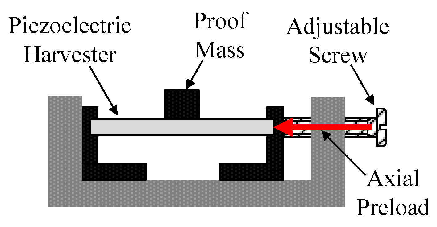
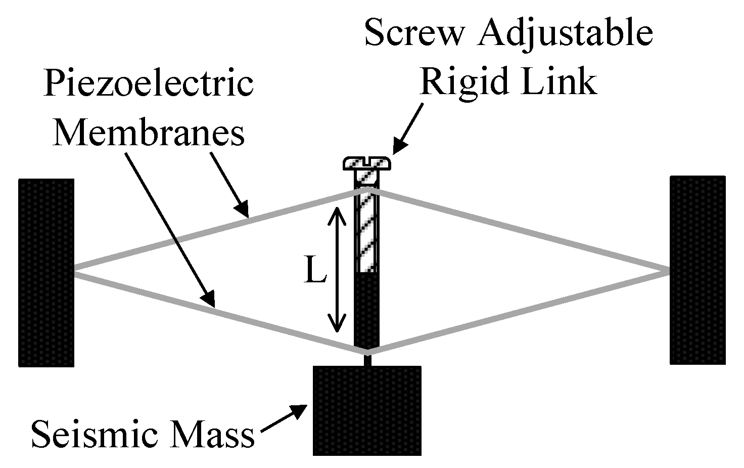
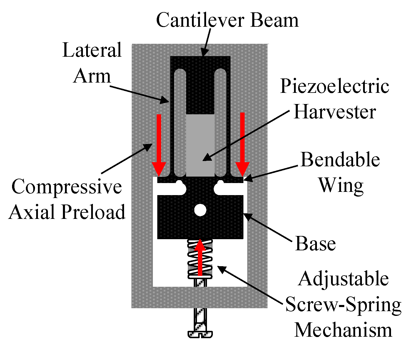
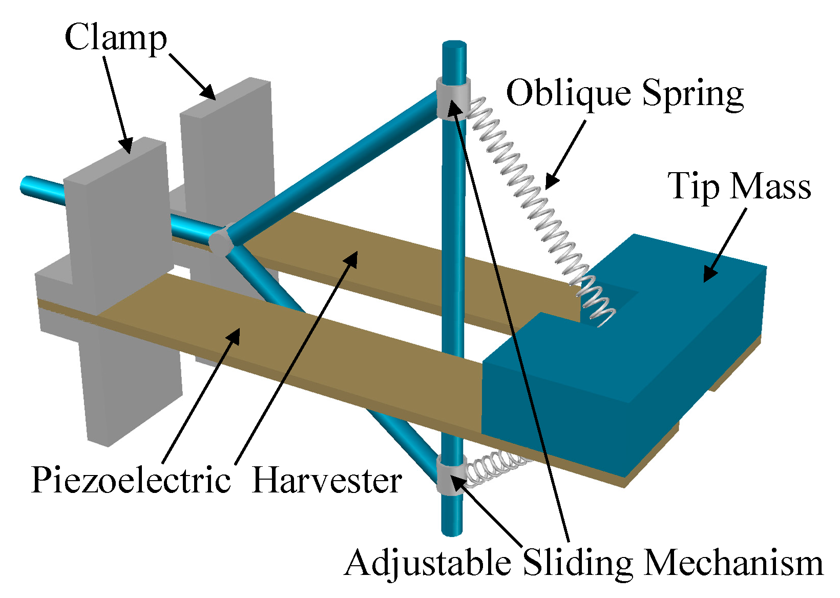
4.3. Axial Loads Based MTTs

Axial loads based MTTs exploit the fact that, by stressing an oscillating beam with axial loads, it is possible to vary its resonance frequency. In fact, an axial load is able to induce additional bending moments in the deflected beam. These moments have an influence on the total restoring force and hence affect the resonance frequency [30,31,32,33,34]. It is worth noting that, in principle, also some of the MTTs described in Section 4.1 and Section 4.2 are based on the application of axial forces. As an example, an axial load can be applied to a cantilever beam by means of magnets in magnetic forces based MTTs, or by means of a piezoelectric actuator in the case of piezoelectric actuators based MTTs. In this section, only the MTTs which do not rely on magnets or on piezoelectric actuators but only on axial mechanical forces in order to obtain loads are discussed. Moreover, another peculiarity of the MTTs discussed in this section is that they are all characterized by a manual actuation and hence no automatic control is possible. Indeed, any regulation of the resonance frequency must be carried out before starting the operation and not during it.
To the best of the authors’ knowledge, the first paper treating this type of MTT is [30] (Figure 14). The study presented herein discusses the design and testing of a tunable P-RVEH, which is based on the adoption of the axial compression of a piezoelectric bimorph by means of an adjustable screw in order to lower its resonance frequency. This device uses a piezoelectric bimorph as the active element and a proof mass is placed at its center.
In [31] the principle of axial loads MTTs is applied by using an extensional mode, rather than a bending mode, resonator mechanism that exploits the force-deflection characteristics of piezoelectric membranes. In particular, the vibration harvester is implemented by coupling two piezoelectric membranes such that a mechanism with a linear force-deflection relationship is obtained (Figure 15). The extensional mode resonator is obtained by suspending a seismic mass to such two piezoelectric membranes. The mechanism becomes frequency tunable thanks to the insertion, in the middle of the membranes, of a length adjustable rigid link that symmetrically pre-tensions both piezoelectric membranes. The rigid link between the membranes is a screw adjustable rigid element whose effective length (L) may be changed by turning the screw.
Moreover, in [32,33] this tuning principle is applied to a P-RVEH. In particular, as shown in Figure 16, the P-RVEH is composed of a piezoelectric cantilever beam with two additional thin lateral arms used to apply an axial preload to the tip of the beam. The arms connect the beam’s tip with two bendable wings, located on both sides of the base where the beam is clamped. The objective of the wings is to receive an external force, by means of an adjustable screw-spring mechanism, and to forward it to the arms, which, in turn, apply the axial load to the tip of the beam. This axial load can be compressive or tensile in order to reduce or increase the resonance frequency of the RVEH.
In [34], a P-RVEH composed of two parallel piezoelectric bimorphs is presented. They are clamped at one end and connected (to each other) at the other end where a tip mass is put on. Adjustable additional stiffness and axial load are used to tune the resonance frequency of the system. In fact, as shown in Figure 17, a sliding mechanism based on two oblique springs connected to the tip mass, is adopted in order to shift the resonance frequency. The application of two oblique springs gives rise to an additional stiffness and axial load and consequently, the dynamic behavior of the system can be tuned manually by an operator. Numerical results are provided to show that the resonance frequency of the P-RVEH can be tuned in a wide range of frequencies using a combination of tip axial load and stiffness.
It is worth noting that axial loads are also applied in the case of MTTs that are based on centrifugal forces during rotations. Such MTTs are specifically designed for rotating harvesters that extract energy from rotational motions instead of linear motions. In particular, in rotating applications, a centrifugal force can modify the stiffness of a cantilever beam and hence its resonance frequency [103,104,105,106,107,108]. This property is profitably used in rotating piezoelectric [103,104,105] or rotating electromagnetic harvesters [106,107,108] where a centrifugal force is always present and can be exploited in order to establish a self-tuning mechanism due to its dependence on the rotational speed.
A summary of the described axial loads based MTTs is reported in Table 4.

4.4. Clamp Position Change Based MTTs

Basically, the operating principle of the clamp position change based MTTs is that of tuning the stiffness of a cantilever beam by changing the position of a clamp supporter placed along this beam. In a clamped cantilever beam, by changing the position of the clamp supporter, it is possible to vary the length of the “free to move” part of the cantilever and hence its stiffness. This principle is also implemented in a commercial resonance frequency tuning kit (KIT-009 by Piezo.com a division of Mide Technology) [35] that is provided together with some commercial P-RVEHs [36]. In particular, such a kit includes all the necessary materials and parts for the positioning and clamping of the P-RVEHs (Figure 18). More in detail, this product is designed for three clamp locations where it is possible to mount the clamp: A middle clamp position that is the default position where the P-RVEH works at its untuned resonance frequency, an external clamp position where the cantilever “free to move” length is reduced (and hence the stiffness is increased), and an internal clamp position where the cantilever “free to move” length is increased (and hence the stiffness is reduced). The position of the clamp can be changed by varying the position of a horizontal bar by means of screws and bolts. Therefore, it is a manual MTT that can be very useful in laboratory tests but it is not suitable for the automatic tuning of the resonance frequency during the operation of the P-RVEH.
In [37] the clamp position change based MTT is conceptually proposed for a piezoelectric bimorph with a tip mass (Figure 19). The equivalent stiffness and mass of the cantilever beam are varied as a function of the supporting position. The theoretical analysis in [37] allows to derive the explicit expressions of the RVEH resonance frequency, output voltage, and output power and is validated by numerical results. No experimental results are reported.
In [38], instead, a technique able to change the clamp support position during the operation of the harvester is presented and discussed with reference to a P-RVEH. The harvester introduced in this paper is composed by an elastic beam partially covered with two-sided piezoelectric patches. As shown in Figure 20, a movable intermediate rigid support is attached to the beam. By adjusting the support’s position (by means of a step motor that drives a linear guide and moves the support to an appropriate position) according to the sensed ambient frequency, the beam’s resonance frequency is made coincident with the vibration frequency. The MTT is actuated in an automatic way but the control unit is supplied by an external source. The authors do not provide information concerning the net harvested power. The resonance frequency versus support position is first calibrated and is stored in a LUT used for the tuning of the harvester. The desired resonance frequency of the P-RVEH is evaluated and the LUT provides the corresponding support position. A control unit (a PC) sends proper control signals to the step motor and subsequently moves the intermediate support to the appropriate position. In order to ensure that the deployed LUT is up-to-date, a feedback control loop is adopted as a fine tuning. In fact, each time the support is moved to the desired position, the fine tuning control automatically takes on and moves the support in two directions to search for the maximum voltage output in the vicinity. Then, the system updates the LUT.
A summary of the described clamp position change based MTTs is reported in Table 5.

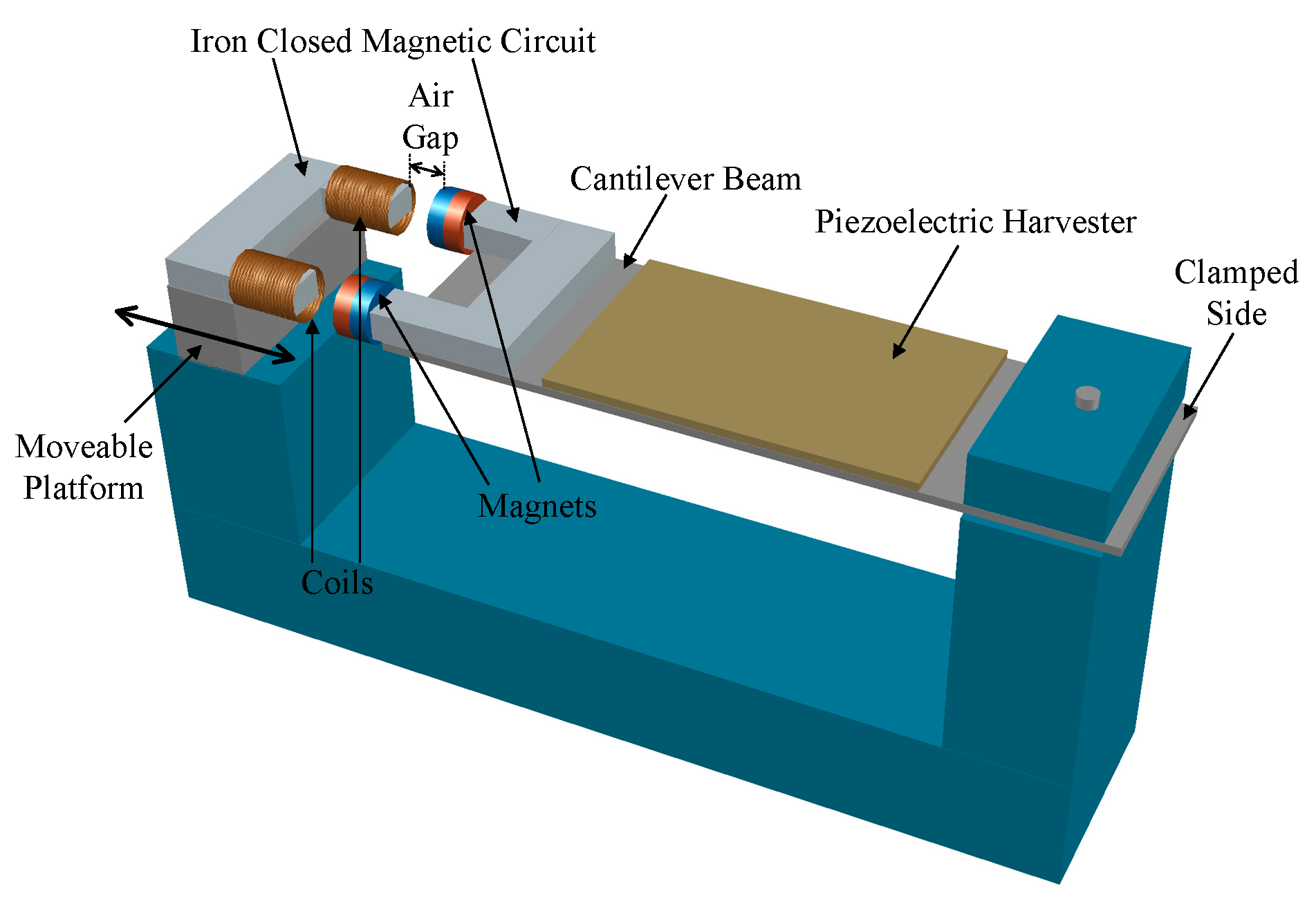
4.5. Variable Reluctance Based MTTs

Variable reluctance based MTTs basically are variations of magnetic forces based MTTs. As stated in Section 4.1, in magnetic forces based MTTs the resonance frequency of a RVEH is varied by acting on the distance between two magnets thus varying, in this way, the stiffness of a cantilever. In variable reluctance based MTTs, a similar principle is used but with the addition of a flux guide between the two tuning magnets, making the system more suitable for microfabrication. In variable reluctance based MTTs, in order to change the magnetic tuning force, the position of a magnetically permeable moveable flux guide, placed between the two tuning magnets, is varied and hence the magnetic reluctance between the two magnets is altered [39,40,41,42]. In other words, in order to vary the force between the magnets and hence the stiffness, the amount of flux that flows between one tuning magnet and the other is altered. This tuning principle is particularly well suited for microfabrication. In fact, a variable reluctance structure with a stationary magnet is more desirable for fabrication using MEMS techniques than a system with a movable magnet. This is due to the difficulty of attaching a permanent magnet to a fragile moveable MEMS structure as a post process. The flux guide can be small and fabricated in a MEMS compatible material such as nickel, with the tuning magnet attached to a robust fixed structure in the MEMS device after MEMS processing.
In [39], two techniques are presented for changing the amount of flux that from a first fixed magnet reaches a second magnet placed on a cantilever beam (Figure 21). In the first case, as shown in Figure 21a, the reluctance path between the two magnets is varied through the action of a flux guide (piece of ferrite) located between them. In this way, the flux that flows from the fixed magnet to the cantilever magnet can be increased with respect to the case of absence of the guide and hence the resonance frequency of the beam can be increased. In the second case, as shown in Figure 21b, the flux guide is not placed between the two magnets but it is placed between the poles of the fixed one. In this way, the flux that flows from the fixed magnet to the cantilever one can be reduced thus reducing the resonance frequency of the beam. The harvester used for testing this variable reluctance based MTT is an E-RVEH and has been presented in [40]. The actuation of the MTT presented in [39] is manual since the piece of ferrite is mounted on a single axis translation stage attached to a manual micrometer.
In [41], the variable reluctance based MTT is applied to a hybrid piezoelectric–electromagnetic RVEH whose resonance frequency is varied as a function of the air gap in a closed magnetic circuit (Figure 22). In particular, the RVEH is composed by flexible micro-fiber composite material pasted on the surface of a cantilever beam for producing the piezoelectric transduction. Instead, the electromagnetic transduction is provided by the combination of magnets, iron, and coils. The magnets are attached on the tip end of the cantilever beam while the coils and the magnetic conductive iron structure are mounted on a movable platform. In this way, a closed magnetic circuit loop is set up across the magnets, irons, coils, and air gap. The magnetic attractive force between the magnets and irons can be considered as an axial tensile force applying to the cantilever beam, which can influence its equivalent stiffness and depends on the air gap. Therefore, the resonance frequency of the cantilever beam can be regulated by adjusting such an air gap. The tuning operation in [41] is manually applied by a human operator that changes the air gap.
In [42], the magnetic flux from a fixed magnet creates a virtual spring by interacting with a magnet on the cantilever of the vibrating harvester. To vary the flux strength, a variable reluctance link is inserted between the two magnets. Such a variable flux link comprises a moveable steel bridging piece. As the bridging piece is mechanically moved by means of a micrometer to vary the reluctance, the change in resonance frequency of the cantilever can be observed. In [42], a macro-scale prototype is implemented and tested. Moreover, a process methodology for fabrication of a MEMS variable reluctance structure is developed.
A summary of the described variable reluctance based MTTs is reported in Table 6.

4.6. Variable Center of Gravity Based MTTs

Variable center of gravity based MTTs exploit the fact that in a cantilever structure with a tip mass it is possible to change the resonance frequency of the structure by varying the position of the center of gravity [43,44,45,46,47,48,49]. In particular, by moving the center of gravity, it is possible to vary the values of both the effective inertial mass and the effective stiffness and hence the value of the resonance frequency. The closer the center of gravity to the tip of the cantilever, the greater the effective mass, the lower the effective stiffness and hence the lower the resonance frequency. Instead, the farther the center of gravity from the tip of the cantilever, the lower the effective mass, the greater the effective stiffness and hence the greater the resonance frequency. In the following, the main variable center of gravity based MTTs are discussed [43,44,45,46]. Additional variable center of gravity based MTTs [48,49] are reported in the Reference Section without a specific description since their working principles are very similar to the ones described in this section.
To the best of the authors’ knowledge the first paper investigating this type of MTT is [43] where a P-RVEH is considered. Indeed, as shown in Figure 23, the tip mass of the device proposed in [43] is made of a fixed and a movable part. In particular, the fixed mass is made of aluminum and is attached to the cantilever tip. The movable part of the tip mass consists of a steel screw that can be moved along the longitudinal direction of the piezoelectric cantilever. Therefore, by manually tightening/untightening the screw, the center of gravity of the structure and the resonance frequency are varied. A fastening stud is used to fix the screw after tuning in order to avoid its movement during the operation under vibration. Unfortunately, in [43] nothing is said on the power extracted from the considered RVEH. The paper provides only tests in open circuit conditions and it is possible to observe that, as expected, the open circuit voltage decreases when the resonance frequency is increased.
In [44], the position of the center of gravity is changed by means of a lever mechanism (Figure 24). In particular, instead of a proof mass at the free end of a piezoelectric beam, a lever with a moving mass is used. The entire system is represented with a spring-mass-damper model with the addition of the lever. One lever end is connected with the spring and the damper to transmit forces into the main direction. The other lever end is connected with the case by a bearing. This means a rotational movement of the lever, but in the presence of small amplitudes it can be simplified with a linear motion. The displacement of the moving mass mounted on the lever directly influences the resonance frequency by changing the effective mass. The position of the moving mass is adjusted by means of a screw.
In [45,46], the principle of variable center of gravity is used in order to make a passive auto-tunable P-RVEH. In particular, the system proposed in [45,46] consists of a unimorph type piezoelectric cantilever (sandwiched between two aluminum electrodes) that is fixed at one end and free to move at the other end. As shown in Figure 25, on the free end of the piezoelectric cantilever a hollow rectangular shaped proof mass is applied. Inside this hollow proof mass two additional masses are encapsulated. They are two solid metallic cylinders free to move inside the hollow mass. Therefore, the hollow rectangular proof mass in addition with the two cylinders acts as a unique tip mass for the cantilever. This structure has an auto-tune resonance frequency property due to a continuous change in the center of gravity when the vibration frequency changes. In particular, when no input vibrations are applied, cylinders acquire a fixed stable position inside the hollow mass. When the cantilever is excited with a vibration source, it starts vibrating at its free end and hence the cylinders start moving inside the hollow proof mass until they reach a stable position. This defines a new center of gravity which is associated with a specific resonance frequency of the device. It is possible to observe that, in the new stable position, cylinders occupy a place where they assume minimum potential energy [47] and the resonance frequency is coincident with the input vibrations frequency. If any change in the frequency of the input vibrations occurs, cylinders again change their positions and settle at a new location inside the hollow mass. In this way, the cantilever is tuned to different natural frequencies leading to a passive auto-tuning capability.
A summary of the described variable center of gravity based MTTs is reported in Table 7.

5. Discussions and Open Issues

In the previous sections a great number of MTTs has been analyzed in detail. In Figure 26, a summary of the power performance of the analyzed MTTs is reported. In particular, each asterisk symbol represents one of the analyzed MTTs. The x-axis is the value of Amax and the y-axis is the corresponding value of PMAX. The various MTTs are identified with different colors. In particular, black asterisk symbols are used for “Magnetic Forces Based MTTs”, red asterisk symbols for “Piezoelectric Actuators Based MTTs”, green asterisk symbols for “Axial Loads Based MTTs”, cyan asterisk symbols for “Clamp Position Change Based MTTs”, blue asterisk symbols for “Variable Reluctance Based MTTs”, and yellow asterisk symbols for “Variable Center of Gravity MTTs”.
In addition, in Figure 27 a summary of the tuning performance of the analyzed MTTs is reported. In particular, in Figure 27 the indicators ΔPR, ΔfR, ΔPL, and ΔfL are summarized. The x-axis represents the values of ΔfR (in the case of asterisk markers) or ΔfL (in the case of circular markers) and the y-axis represents the values of ΔPR (in the case of asterisk markers) or ΔPL (in the case of circular markers). The various MTTs are identified with the same colors as in Figure 26.
The above figures try to put in evidence, in a graphical manner, the features of the discussed MTTs. Of course, not all the MTTs are reported since, in many cases, as evidenced in the previous tables, fundamental performance lack data. As Figure 26 is concrened, a much more useful y-axis for fair comparisons would have been the power density instead of the power. However, once again, complete information on geometric dimensions is rarely reported in the scientific papers.
Additionally, in general, this study clearly underlines the necessity of identifying universally recognized test conditions as the shape of vibrations, the amplitude, the frequency and, at the same time, a minimum set of tests results and characteristics to record such as the indicators that have been defined in Section 3 are concerened. More or less such as standard test conditions and results in photovoltaic applications.
On the basis of the detailed overview of the MTTs proposed in the previous sections, it is possible to identify a number of open issues that can be helpful for researchers in the field of MTTs for RVEHs.
  • First of all, it is possible to observe that, in all the papers focusing on MTTs, no attention at all is paid to ETTs. As it has been evidenced in Section 2, for the optimal exploitation of a RVEH both tuning techniques should be applied. Therefore, the need exists for a study of the joint application of both MTTs and ETTs. In addition, since in most papers reported in Figure 26 and Figure 27 a pure resistive load is considered, it is possible to state they are associated to underestimated results as their power performance is concerened.
  • An important observation is worth noting. All the MTTs are based on the fact that RVEHs can be schematically represented (as discussed in Section 2.1) by means of spring-mass-damper systems. The mechanical resonance frequency of such systems (see (30) and (31)) depends on the values of the mass and of the stiffness and therefore it can be varied by acting on such two parameters values. In particular, for obvious reasons, it is easier to adopt a MTT that, during the RVEH operation, changes the stiffness rather than the value of the oscillating mass. In fact, nearly all the analyzed MTTs are based on the change of the stiffness. The application of a MTT for the increase of the resonance frequency by varying only the stiffness of the spring-mass-damper system is preferable also from another point of view. In fact, at least in principle, on the basis of (30) and (31), the increase of fres by means of the variation of the stiffness does not affect the maximum extractable power PMAX. Instead, the increase of fres by acting on the movable mass, requires the reduction of the value of such a mass with a consequent reduction of the maximum extractable power PMAX as shown in (32) and (33). It is worth noting instead that, in the case of application of a MTT for reducing fres, the variation of the moving mass (although unpractical) should be preferred with respect to that of the stiffness. In fact, at least in principle, on the basis of (32) and (33), the value of such a mass should be increased with a consequent increase of the maximum extractable power PMAX.
  • From the analysis reported in Section 4 also another important aspect must be underlined. The tuning periods of the MTTs usually have too high values that can lead to questionable practical applicability of these techniques. In fact, a large tuning period means that a change in the frequency can be carried out only with a low speed, leading to quite slow MTTs that are able to track only vibrations characterised by relative slow dynamics. Therefore, an important objective for future research activities must be the reduction of the values of the tuning periods.
  • It is clear that MTTs that are based on a closed-loop control are surely more robust and do not need a precharacterization of the system. However, they need sensors in order to implement the feedback circuitry and hence require much energy for their operation. Instead the MTTs that are based on an open-loop control require less energy but need a precharacterization of the system (e.g., for the definition of a LUT) and are less robust since they are affected by possible errors due to system parameters change. Trade-off solutions between closed-loop and open-loop adopting LUTs with “learning capability” seem to be very promising [25,26,38]. The MTTs that are more suitable for closed-loop controls are the piezoelectric actuators based MTTs since they can be simply controlled by acting on a voltage. In principle, it could be also possible to implement a MTT that is controlled in a closed-loop by acting on a current flowing in a proper coil in a magnetic forces based MTT. No system of this type has been proposed in the literature yet.
  • A further aspect to underline is that, at the moment, all the MTTs are designed and tested in the case of purely sinusoidal vibrations. However, as stated in Section 3, purely sinusoidal vibrations are nearly impossible to be found in practical applications. Actual vibrations are usually periodic (with a fundamental component plus harmonics), random (with an energy content that is distributed over a wide frequency spectrum), or single event motions (as in the case of impacts) [84,85,86]. This is a crucial aspect and is an open issue for nearly all the RVEHs applications. In particular, as it can be observed from Section 4, many MTTs are based on the measurement of the vibration frequency. In the presence of purely sinusoidal vibrations such a task is quite simple. However, when the input vibrations are non-sinusoidal the task becomes much more complex and the detection of the vibration zero-crossings could mislead the MTT. A solution to such a problem could be a perturbative approach such as the one that is implemented in maximum power point tracking applications for RVEHs [98,100]. The perturbative approach could get rid of the measurement of the vibration frequency, since it could be based on the measurement of the extracted power and could adapt the RVEH’s resonance frequency in order to maximize such a power. Moreover, in this case the gap in the literature on such an important issue needs to be filled.
  • Another important observation concerns the compliance of MTTs with miniaturization. In fact, miniaturization is of crucial importance in order to make RVEHs equipped with MTTs and suitable for wireless sensors networks or biosensors applications. Obviously, all the MTTs that are implemented by using cumbersome motors or mechanical actuators are not compatible with miniaturized systems and therefore further research on such a topic is necessary.
  • Among all the analyzed MTTs, a very interesting property is the “passive self-tuning” capability that characterizes the variable center of gravity based MTT proposed in [45,46]. In particular, it has an auto-tune resonance frequency property due to the continuous change in the center of gravity following the vibration frequency change. This is a very important mechanical property that leads to a system that does not need any external control circuitry and its associated energy consumption. Such an interesting property could be the starting point for the future identification of other types of structures with auto-tuning capabilities.

6. Conclusions

The maximization of the extraction of power is of fundamental importance in RVEH applications and the crucial aspect of such a task is represented by the optimization of the mechanical resonance frequency. MTTs are those techniques able to regulate the value of the RVEH mechanical resonance frequency in order to make it coincident with the vibration frequency. In this paper a review, classification and comparison of the main MTTs presented in the literature during the last years has been reported. In particular, some important classification criteria and indicators have been defined and they have been used to put in evidence the differences existing among the various MTTs in order to allow the reader an easy comparison of their performance. Finally, the open issues that have emerged from the literature review have been highlighted.

Author Contributions

Conceptualization, L.C. and M.V.; methodology, L.C. and M.V.; software, L.C. and M.V.; validation, L.C. and M.V.; formal analysis, L.C. and M.V.; investigation, L.C. and M.V.; resources, L.C. and M.V.; data curation, L.C. and M.V.; writing—original draft preparation, L.C. and M.V.; writing—review and editing, L.C. and M.V.; visualization, L.C. and M.V. All authors have read and agreed to the published version of the manuscript.

Funding

This research was funded by “VALERE: VAnviteLli pEr la RicErca” research program of Università degli Studi della Campania “Luigi Vanvitelli”.

Conflicts of Interest

The authors declare no conflict of interest. The funders had no role in the design of the study; in the collection, analyses, or interpretation of data; in the writing of the manuscript, or in the decision to publish the results.

References

  1. Siang, J.; Lim, M.H.; Salman Leong, M. Review of vibration-based energy harvesting technology: Mechanism and architectural approach. Int. J. Energy Res. 2018, 42, 1866–1893. [Google Scholar] [CrossRef]
  2. Abdelkareem, M.A.A.; Xu, L.; Ahmed Ali, M.K.; Elagouz, A.; Mi, J.; Guo, S.; Liu, Y.; Zuo, L. Vibration energy harvesting in automotive suspension system: A detailed review. Appl. Energy 2018, 229, 672–699. [Google Scholar] [CrossRef]
  3. Luigi, C.; Massimo, V.; Yu, P.; Zuo, L. Maximizing the power extraction from train suspension energy harvesting system. In Proceedings of the ASME 2019 International Design Engineering Technical Conferences and Computers and Information in Engineering Conference, Anaheim, CA, USA, 18–21 August 2019. Volume 8: 31st Conference on Mechanical Vibration and Noise. [Google Scholar] [CrossRef]
  4. Zhang, Y.; Guo, K.; Wang, D.; Chen, C.; Li, X. Energy conversion mechanism and regenerative potential of vehicle suspensions. Energy 2017, 119, 961–970. [Google Scholar] [CrossRef]
  5. Zuo, L.; Scully, B.; Shestani, J.; Zhou, Y. Design and characterization of an electromagnetic energy harvester for vehicle suspensions. Smart Mater. Struct. 2010, 19, 045003. [Google Scholar] [CrossRef] [Green Version]
  6. Balato, M.; Costanzo, L.; Vitelli, M. MPPT in wireless sensor nodes supply systems based on electromagnetic vibration harvesters for freight wagons applications. IEEE Trans. Ind. Electron. 2017, 64, 3576–3586. [Google Scholar] [CrossRef]
  7. Challa, V.R.; Prasad, M.G.; Shi, Y.; Fisher, F.T. A vibration energy harvesting device with bidirectional resonance frequency tunability. Smart Mater. Struct. 2008, 1, 15035. [Google Scholar] [CrossRef]
  8. Podder, P.; Constantinou, P.; Mallick, D.; Amann, A.; Roy, S. Magnetic tuning of nonlinear MEMS electromagnetic vibration energy harvester. J. Microelectromech. Syst. 2017, 26, 539–549. [Google Scholar] [CrossRef]
  9. Podder, P.; Constantinou, P.; Amann, A.; Roy, S. Frequency adjustable MEMS vibration energy harvester. J. Phys. Conf. Ser. 2016, 757, 012037. [Google Scholar] [CrossRef] [Green Version]
  10. Dong, L.; Prasad, M.G.; Fisher, F.T. Two-dimensional resonance frequency tuning approach for vibration-based energy harvesting. Smart Mater. Struct. 2016, 6, 65019. [Google Scholar] [CrossRef]
  11. Aboulfotoh, N.A.; Arafa, M.H.; Megahed, S.M. A self-tuning resonator for vibration energy harvesting. Sens. Actuators A Phys. 2013, 201, 328–334. [Google Scholar] [CrossRef]
  12. Zhu, D.; Roberts, S.; Tudor, M.J.; Beeby, S.P. Closed loop frequency tuning of a vibration-based micro-generator. In Proceedings of the PowerMEMS 2008 microEMS2008, Sendai, Japan, 9–12 November 2008; pp. 229–232. [Google Scholar]
  13. Zhu, D.; Roberts, S.; Tudor, M.J.; Beeby, S.P. Design and experimental characterization of a tunable vibration-based electromagnetic micro-generator. Sens. Actuators A Phys. 2010, 158, 284–293. [Google Scholar] [CrossRef] [Green Version]
  14. Al-Ashtari, W.; Hunstig, M.; Hemsel, T.; Sextro, W. Frequency tuning of piezoelectric energy harvesters by magnetic force. Smart Mater. Struct. 2012, 3, 35019. [Google Scholar] [CrossRef]
  15. Hoffmann, D.; Willmann, A.; Hehn, T.; Folkmer, B.; Manoli, Y. A self-adaptive energy harvesting system. Smart Mater. Struct. 2016, 3, 35013. [Google Scholar] [CrossRef]
  16. Hoffmann, D.; Willmann, A.; Folkmer, B.; Manoli, Y. Tunable vibration energy harvester for condition monitoring of maritime gearboxes. J. Phys. Conf. Ser. 2014, 557, 012099. [Google Scholar] [CrossRef]
  17. Mansour, M.O.; Arafa, M.H.; Megahed, S.M. Resonator with magnetically adjustable natural frequency for vibration energy harvesting. Sens. Actuators A Phys. 2010, 163, 297–303. [Google Scholar] [CrossRef]
  18. Chung, T.K.; Wang, C.M.; Yeh, P.C.; Liu, T.W.; Tseng, C.Y.; Chen, C.C. A three-axial frequency-tunable piezoelectric energy harvester using a magnetic-force configuration. IEEE Sens. J. 2014, 14, 3152–3163. [Google Scholar] [CrossRef] [Green Version]
  19. Li, M.; Wen, Y.; Li, P.; Yang, J. A magnetostrictive/piezoelectric laminate transducer based vibration energy harvester with resonance frequency tunability. In Proceedings of the 2011 IEEE Sensors Proceedings, Limerick, Ireland, 28–31 October 2011; pp. 1768–1771. [Google Scholar] [CrossRef]
  20. Davidson, J.R.; Mo, C. Piezoelectric energy harvesting with frequency tuning for ventilation system monitoring. Int. J. Eng. Sci. Innov. Technol. 2013, 5, 114–124. [Google Scholar]
  21. Wischke, M.; Masur, M.; Goldschmidtboeing, F.; Woias, P. Piezoelectrically tunable electromagnetic vibration harvester. In Proceedings of the 2010 IEEE 23rd International Conference on Micro Electro Mechanical Systems (MEMS), Hong Kong, China, 24–28 January 2010; pp. 1199–1202. [Google Scholar] [CrossRef]
  22. Wischke1, M.; Masur, M.; Goldschmidtboeing, F.; Woias, P. Electromagnetic vibration harvester with piezoelectrically tunable resonance frequency. J. Micromech. Microeng. 2010, 20, 035025. [Google Scholar] [CrossRef]
  23. Peters, C.; Maurath, D.; Schock, W.; Mezger, F.; Manoli, Y. A closed-loop wide-range tunable mechanical resonator for energy harvesting systems. J. Micromech. Microeng. 2009, 19, 094004. [Google Scholar] [CrossRef]
  24. Peters, C.; Maurath, D.; Schock, W.; Manoli, Y. Novel electrically tunable mechanical resonator for energy harvesting. In Proceedings of the PowerMEMS 2008, Sendai, Japan, 9–12 November 2008; pp. 253–256. [Google Scholar]
  25. Eichhorn, C.; Tchagsim, R.; Wilhelm, N.; Woias, P. A smart and self-sufficient frequency tunable vibration energy harvester. J. Micromech. Microeng. 2011, 21, 104003. [Google Scholar] [CrossRef]
  26. Eichhorn, C.; Tchagsim, R.; Wilhelm, N.; Goldschmidtboeing, F.; Woias, P. A compact piezoelectric energy harvester with a large resonance frequency tuning range. In Proceedings of the PowerMEMS 2010, Leuven, Belgium, 1–3 December 2010; pp. 207–211. [Google Scholar]
  27. Eichhorn, C.; Goldschmidtboeing, F.; Porro, Y.; Woias, P. A piezoelectric harvester with an integrated frequency-tuning mechanism. In Proceedings of the PowerMEMS, Washington, DC, USA, 1–4 December 2009; pp. 45–48. [Google Scholar]
  28. Eichhorn, C.; Tchagsim, R.; Wilhelm, N.; Biancuzzi, G.; Woias, P. An energy-autonomous self-tunable piezoelectric vibration energy harvesting system. In Proceedings of the 2011 IEEE 24th International Conference on Micro Electro Mechanical Systems, Cancun, Mexico, 23–27 January 2011; pp. 1293–1296. [Google Scholar]
  29. Cheng, Y.; Wu, N.; Wang, Q. An efficient piezoelectric energy harvester with frequency self-tuning. J. Sound Vib. 2017, 396, 69–82. [Google Scholar] [CrossRef]
  30. Leland, E.S.; Wright, P.K. Resonance tuning of piezoelectric vibration energy scavenging generators using compressive axial preload. Smart Mater. Struct. 2006, 15, 1413. [Google Scholar] [CrossRef]
  31. Morris, D.J.; Youngsman, J.M.; Anderson, M.J.; Bahr, D.F. A resonant frequency tunable, extensional mode piezoelectric vibration harvesting mechanism. Smart Mater. Struct. 2008, 17, 65021. [Google Scholar] [CrossRef]
  32. Eichhorn, C.; Goldschmidtboeing, F.; Woias, P. Bidirectional frequency tuning of a piezoelectric energy converter based on a cantilever beam. J. Micromech. Microeng. 2009, 19, 94006. [Google Scholar] [CrossRef]
  33. Eichhorn, C.; Goldschmidtboeing, F.; Woias, P. A frequency tunable piezoelectric energy converter based on a cantilever beam. In Proceedings of the PowerMEMS 2008, Sendai, Japan, 9–12 November 2008; pp. 309–312. [Google Scholar]
  34. Niri, E.D.; Salamone, S. A passively tunable mechanism for a dual bimorph energy harvester with variable tip stiffness and axial load. Smart Mater. Struct. 2012, 21, 125025. [Google Scholar] [CrossRef]
  35. Mounting Guidelines. Available online: https://support.piezo.com/article/126-mounting-guidelines (accessed on 18 January 2020).
  36. Piezoelectric Energy Harvesters. Available online: https://piezo.com/collections/piezoelectric-energy-harvesters?_=pf&pf_t_quantity=Quantity__1 (accessed on 18 January 2020).
  37. Yun, W.; He, H.; Xu, R. An analytical model for a piezoelectric vibration energy harvester with resonance frequency tunability. Adv. Mech. Eng. 2015, 7. [Google Scholar] [CrossRef] [Green Version]
  38. Huang, S.C.; Lin, K.A. A novel design of a map-tuning piezoelectric vibration energy harvester. Smart Mater. Struct. 2012, 21, 85014. [Google Scholar] [CrossRef]
  39. Ayala-Garcia, I.N.; Mitcheson, P.D.; Yeatman, E.M.; Zhu, D.; Tudor, J.; Beeby, S.P. Magnetic tuning of a kinetic energy harvester using variable reluctance. Sens. Actuators A Phys. 2013, 189, 266–275. [Google Scholar] [CrossRef]
  40. Beeby, S.P.; Torah, R.N.; Tudor, M.J.; Glynne-Jones, P.; Donnell Saha, C.R.; Roy, S. A micro electromagnetic generator for vibration energy harvesting. J. Micromech. Microeng. 2007, 17, 1257–1265. [Google Scholar] [CrossRef]
  41. Xia, H.; Chen, R.; Ren, L. Parameter tuning of piezoelectric–electromagnetic hybrid vibration energy harvester by magnetic force: Modeling and experiment. Sens. Actuators A Phys. 2017, 257, 73–83. [Google Scholar] [CrossRef]
  42. Mukherjee, A.G.; Mitcheson, P.D.; Wright, S.W.; Yeatman, E.M. Tuning resonant energy harvesters using a variable reluctance link. In Proceedings of the Technical Digest Power MEMS 2011, Soul, Korea, 23–27 January 2011; pp. 11–14. [Google Scholar]
  43. Wu, X.; Lin, J.; Kato, S.; Zhang, K.; Ren, T.; Liu, L. A frequency adjustable vibration energy harvester. In Proceedings of the PowerMEMS, Sendai, Japan, 9–12 November 2008; pp. 245–248. [Google Scholar]
  44. Schaufuss, J.; Scheibner, D.; Mehner, J. New approach of frequency tuning for kinetic energy harvesters. Sens. Actuators A Phys. 2011, 171, 352–360. [Google Scholar] [CrossRef]
  45. Chandwani, J.; Somkuwar, R.; Deshmukh, R. Multi-band piezoelectric vibration energy harvester for low-frequency applications. Microsyst Technol. 2019, 25, 3867–3877. [Google Scholar] [CrossRef]
  46. Somkuwar, R.; Chandwani, J.; Deshmukh, R. Wideband auto-tunable vibration energy harvester using change in centre of gravity. Microsyst Technol. 2018, 24, 3033–3044. [Google Scholar] [CrossRef]
  47. Kozinsky, I. Study of passive self-tuning resonator for broadband power harvesting. In Proceedings of the Power MEMS, Washington, DC, USA, 1–4 December 2009; pp. 388–389. [Google Scholar]
  48. Karadag, C.; Topaloglu, N. A self-sufficient and frequency tunable piezoelectric vibration energy harvester. ASME J. Vib. Acoust. 2016, 139. [Google Scholar] [CrossRef]
  49. Aboulfotoh, N.; Twiefel, J.; Krack, M.; Wallaschek, J. Experimental study on performance enhancement of a piezoelectric vibration energy harvester by applying self-resonating behavior. Energy Harvest. Syst. 2017, 4, 131–136. [Google Scholar] [CrossRef]
  50. Madinei, H.; Khodaparast, H.H.; Adhikari, S.; Friswell, M.I.; Fazeli, M. Adaptive tuned piezoelectric MEMS vibration energy harvester using an electrostatic device. Eur. Phys. J. Spec. Top. 2015, 224, 2703–2717. [Google Scholar] [CrossRef]
  51. Heit, J.; Christensen, D.; Roundy, S. A vibration energy harvesting structure, tunable over a wide frequency range using minimal actuation. In Proceedings of the ASME 2013 Conference on Smart Materials, Adaptive Structures and Intelligent Systems, Snowbird, UT, USA, 16–18 September 2013; Volume 2: Mechanics and Behavior of Active Materials; Structural Health Monitoring; Bioinspired Smart Materials and Systems; Energy Harvesting. American Society of Mechanical Engineers: New York, NY, USA, 2013; Volume 2. [Google Scholar]
  52. Anup, P.; Batra, R.C. Beam-based vibration energy harvesters tunable through folding. J. Vib. Acoust. 2019, 141, 011003. [Google Scholar]
  53. Wang, X.; Chen, C.; Wang, N.; San, H.; Yu, Y.; Halvorsen, E.; Chen, X. A frequency and bandwidth tunable piezoelectric vibration energy harvester using multiple nonlinear techniques. Appl. Energy 2017, 190, 368–375. [Google Scholar] [CrossRef]
  54. Ibrahim, P.; Nassar, O.; Arafa, M.; Anis, Y. On adjusting the rotary inertia of a cantilever-type energy harvester for wideband operation. Procedia Eng. 2017, 199, 3422–3427. [Google Scholar] [CrossRef]
  55. Xie, L.; Du, R. Frequency tuning of a nonlinear electromagnetic energy harvester. ASME. J. Vib. Acoust. 2013, 136. [Google Scholar] [CrossRef]
  56. Lee, B.C.; Chung, G.S. Frequency tuning design for vibration-driven electromagnetic energy harvester. IET Renew. Power Gener. 2015, 9, 801–808. [Google Scholar] [CrossRef]
  57. Lee, B.C.; Chung, G.S. A novel frequency tuning design for vibration-driven electromagnetic energy harvester. In Proceedings of the 2015 IEEE SENSORS, Busan, Korea, 1–4 November 2015; pp. 1–4. [Google Scholar] [CrossRef]
  58. Hassan, E.; Eugeni, M.; Gaudenzi, P. A review on mechanisms for piezoelectric-based energy harvesters. Energies 2018, 11, 1850. [Google Scholar]
  59. Yang, Z.; Zhou, S.; Zu, J.; Inman, D. High-performance piezoelectric energy harvesters and their applications. Joule 2018, 2, 642–697. [Google Scholar] [CrossRef] [Green Version]
  60. Liu, H.; Zhong, J.; Lee, C.; Lee, S.-W.; Lin, L. A comprehensive review on piezoelectric energy harvesting technology: Materials, mechanisms, and applications. Appl. Phys. Rev. 2018, 5, 041306. [Google Scholar] [CrossRef]
  61. Tan, Y.; Dong, Y.; Wang, X. Review of MEMS electromagnetic vibration energy harvester. J. Microelectromech. Syst. 2017, 26, 1–16. [Google Scholar] [CrossRef]
  62. Balato, M.; Costanzo, L.; Vitelli, M. Maximization of the extracted power in resonant electromagnetic vibration harvesters applications employing bridge rectifiers. Sens. Actuators A Phys. 2017, 263, 63–75. [Google Scholar] [CrossRef]
  63. Naifar, S.; Bradai, S.; Viehweger, C.; Kanoun, O. Survey of electromagnetic and magnetoelectric vibration energy harvesters for low frequency excitation. Measurement 2017, 106, 251–263. [Google Scholar] [CrossRef]
  64. Yasuyuki, N.; Uenishi, K. Electrostatic MEMS vibration energy harvesters inside of tire treads. Sensors 2019, 19, 890. [Google Scholar] [CrossRef] [Green Version]
  65. Balato, M.; Costanzo, L.; Vitelli, M. Closed-form analysis of switchless electrostatic vibration energy harvesters. In Proceedings of the Ecological Vehicles and Renewable Energies (EVER), 2015 Tenth International Conference on, Monte Carlo, Monaco, 31 March–2 April 2015; pp. 1–7. [Google Scholar] [CrossRef]
  66. Kempitiya, A.; Borca-Tasciuc, D.A.; Hella, M.M. Analysis and optimization of asynchronously controlled electrostatic energy harvesters. IEEE Trans. Ind. Electron. 2012, 59, 456–463. [Google Scholar] [CrossRef]
  67. Thomson, G.; Yurchenko, D.; Val, D.V.; Zhang, Z. Predicting energy output of a stochastic nonlinear dielectric elastomer generator. Energy Convers. Manag. 2019, 196, 1445–1452. [Google Scholar] [CrossRef]
  68. Thomson, G.; Lai, Z.; Val, D.V.; Yurchenko, D. Advantages of nonlinear energy harvesting with dielectric elastomers. J. Sound Vib. 2019, 442, 167–182. [Google Scholar] [CrossRef]
  69. Backman, G.; Lawton, B.; Morley, N.A. Magnetostrictive energy harvesting: Materials and design study. IEEE Trans. Magn. 2019. [Google Scholar] [CrossRef]
  70. Narita, F.; Fox, M. A review on piezoelectric, magnetostrictive, and magnetoelectric materials and device technologies for energy harvesting applications. Adv. Eng. Mater. 2018, 20, 1700743. [Google Scholar] [CrossRef] [Green Version]
  71. Yang, Z.; Nakajima1, K.; Onodera, R.; Tayama, T.; Chiba, D.; Narita, F. Magnetostrictive clad steel plates for high-performance vibration energy harvesting. Appl. Phys. Lett. 2018, 112, 073902. [Google Scholar] [CrossRef]
  72. Xu, L.; Jiang, T.; Lin, P.; Shao, J.; He, C.; Zhong, W.; Chen, X.; Wang, Z. Coupled Triboelectric Nanogenerator Networks for Efficient Water Wave Energy Harvesting. ACS Nano 2018, 12, 1849–1858. [Google Scholar] [CrossRef] [PubMed]
  73. Wang, Z.L.; Jiang, T.; Xu, L. Toward the blue energy dream by triboelectric nanogenerator networks. Nano Energy 2017, 39, 9–23. [Google Scholar] [CrossRef]
  74. Costanzo, L.; Lo Schiavo, A.; Vitelli, M. Power extracted from piezoelectric harvesters driven by non-sinusoidal vibrations. IEEE Trans. Circuits Syst. I Regul. Pap. 2019, 66, 1291–1303. [Google Scholar] [CrossRef]
  75. Balato, M.; Costanzo, L.; Vitelli, M. Resonant electromagnetic vibration harvesters: Determination of the equivalent electric circuit parameters and simplified closed-form analysis for the identification of the optimal diode bridge rectifier DC load. Int. J. Electr. Power Energy Syst. 2017, 84, 111–123. [Google Scholar] [CrossRef]
  76. Al-Ashtari, W.; Hunstig, M.; Hemsel, T.; Sextro, W. Analytical determination of characteristic frequencies and equivalent circuit parameters of a piezoelectric bimorph. J. Intell. Mater. Syst. Struct. 2012, 23, 15–23. [Google Scholar] [CrossRef]
  77. Kong, C.S. A general maximum power transfer theorem. IEEE Trans. Educ. 1995, 38, 296–298. [Google Scholar] [CrossRef]
  78. Dhakar, L.; Liu, H.; Tay, F.E.H.; Lee, C. A new energy harvester design for high power output at low frequencies. Sens. Actuators A Phys. 2013, 199, 344–352. [Google Scholar] [CrossRef]
  79. Du, S.; Yu, J.; Seshia, A. Maximizing output power in a cantilevered piezoelectric vibration energy harvester by electrode design. J. Phys. Conf. Ser. 2015, 660, 012114. [Google Scholar] [CrossRef]
  80. Foisal, A.R.M.; Lee, B.; Chung, G. Fabrication and performance optimization of an AA size electromagnetic energy harvester using magnetic spring. In Proceedings of the Sensors 2011 IEEE, Limerick, Ireland, 28–31 October 2011; pp. 1125–1128. [Google Scholar] [CrossRef]
  81. Frank, G.; Woias, P. Characterization of different beam shapes for piezoelectric energy harvesting. J. Micromech. Microeng. 2008, 18, 104013. [Google Scholar]
  82. Ben Ayed, S.; Abdelkefi, A.; Najar, F.; Hajj, M.R. Design and performance of variable-shaped piezoelectric energy harvesters. J. Intell. Mater. Syst. Struct. 2014, 25, 174–186. [Google Scholar] [CrossRef]
  83. Muthalif, A.G.A.; Diyana Nordin, N.H. Optimal piezoelectric beam shape for single and broadband vibration energy harvesting: Modeling, simulation and experimental results. Mech. Syst. Signal Process. 2015, 54, 417–426. [Google Scholar] [CrossRef]
  84. Rahman, M.F.B.A.B.; Kok, S.L. Investigation of useful ambient vibration sources for the application of energy harvesting. In Proceedings of the 2011 IEEE Students Conference on Research and Development (SCOReD), Cyberjaya, Malaysia, 19–20 December 2011; pp. 391–396. [Google Scholar]
  85. Neri, I.; Neild, S.; Travasso, F.; Mincigrucci, R.; Vocca, H.; Orfei, F.; Gammaitoni, L. A real vibration database for kinetic energy harvesting application. J. Intell. Mater. Syst. Struct. 2012. [Google Scholar] [CrossRef]
  86. Petersen, D.; Howarda, C.; Sawalhi, N.; Ahmadia, A.M.; Singha, S. Analysis of bearing stiffness variations, contact forces and vibrations in radially loaded double row rolling element bearings with raceway defects. Mech. Syst. Signal Proc. 2015, 50–51, 139–160. [Google Scholar] [CrossRef]
  87. Zhu, D.; Tudor, M.J.; Beeby, S.P. Strategies for increasing the operating frequency range of vibration energy harvesters: A review. Meas. Sci. Technol. 2010, 21, 022001. [Google Scholar] [CrossRef]
  88. Yang, Z.; Zu, J.; Xu, Z. Reversible nonlinear energy harvester tuned by tilting and enhanced by nonlinear circuits. IEEE/ASME Trans. Mechatron. 2016, 21, 2174–2184. [Google Scholar] [CrossRef]
  89. Liu, H.; Gudla, S.; Hassani, F.A.; Heng, C.H.; Lian, Y.; Lee, C. Investigation of the nonlinear electromagnetic energy harvesters from hand shaking. IEEE Sens. J. 2015, 15, 2356–2364. [Google Scholar] [CrossRef]
  90. Andò, B.; Baglio, S.; Bulsara, A.R.; Marletta, V.; Pistorio, A. Experimental and theoretical investigation of a nonlinear vibrational energy harvester. Procedia Eng. 2015, 120, 1024–1027. [Google Scholar] [CrossRef] [Green Version]
  91. Li, C.; Wu, S.; Luk, P.C.K.; Gu, M.; Jiao, Z. Enhanced bandwidth nonlinear resonance electromagnetic human motion energy harvester using magnetic springs and ferrofluid. IEEE/ASME Trans. Mechatron. 2019, 24, 710–717. [Google Scholar] [CrossRef] [Green Version]
  92. Ullah, K.F. Review of non-resonant vibration based energy harvesters for wireless sensor nodes. J. Renew. Sustain. Energy 2016, 8, 044702. [Google Scholar]
  93. Mergen, T.N.; Ghayesh, H.; Arjomandi, M. Ambient vibration energy harvesters: A review on nonlinear techniques for performance enhancement. Int. J. Eng. Sci. 2018, 127, 162–185. [Google Scholar] [CrossRef]
  94. Haim, A.; Har-nes, I. Analysis and experimental validation of a piezoelectric harvester with enhanced frequency bandwidth. Materials 2018, 11, 1243. [Google Scholar] [CrossRef] [Green Version]
  95. Kazmierski, T.J.; Beeby, S. Energy Harvesting Systems; Springer: Berlin, Germany, 2014. [Google Scholar]
  96. Bowden, J.A.; Burrow, S.G.; Cammarano, A.; Clare, L.R.; Mitcheson, P.D. Switched-mode load impedance synthesis to parametrically tune electromagnetic vibration energy harvesters. IEEE/ASME Trans. Mechatron. 2015, 20, 603–610. [Google Scholar] [CrossRef]
  97. Costanzo, L.; Lo Schiavo, A.; Vitelli, M. Power maximization from resonant electromagnetic vibration harvesters feeding bridge rectifiers. Int. J. Circ. Theor. Appl. 2019, 47, 87–102. [Google Scholar] [CrossRef] [Green Version]
  98. Balato, M.; Costanzo, L.; Lo Schiavo, A.; Vitelli, M. Optimization of both perturb & observe and open circuit voltage mppt techniques for resonant piezoelectric vibration harvesters feeding bridge rectifiers. Sens. Actuators A Phys. 2018, 278, 85–97. [Google Scholar] [CrossRef]
  99. Kamali, S.H.; Moallem, M.; Arzanpour, S. A self-tuning vibration energy harvester with variable loads and maximum allowable displacement. Smart Mater. Struct. 2018, 27, 105015. [Google Scholar] [CrossRef]
  100. Costanzo, L.; Vitelli, M. Resonant electromagnetic vibration harvesters applications: Optimization of P&O MPPT technique parameters. In Proceedings of the Thirteenth International Conference on Ecological Vehicles and Renewable Energies (EVER), Monte-Carlo, Monaco, 10–12 April 2018; pp. 1–8. [Google Scholar] [CrossRef]
  101. Du, S.; Jia, Y.; Do, C.D.; Seshia, A.A. An efficient sshi interface with increased input range for piezoelectric energy harvesting under variable conditions. IEEE J. Solid State Circuits 2016, 51, 2729–2742. [Google Scholar] [CrossRef] [Green Version]
  102. Rincón-Mora, G.A.; Yang, S. Tiny piezoelectric harvesters: Principles, constraints, and power conversion. IEEE Trans. Circuits Syst. I Regul. Pap. 2016, 63, 639–649. [Google Scholar] [CrossRef]
  103. Gu, L.; Livermore, C. Passive self-tuning energy harvester for extracting energy from rotational motion. Appl. Phys. Lett. 2010, 97, 081904. [Google Scholar] [CrossRef]
  104. Gu, L.; Livermore, C. Compact passively self-tuning energy harvesting for rotating applications. Smart Mater. Struct. 2012, 21, 015002. [Google Scholar] [CrossRef]
  105. Wang, Y.-J.; Chuang, T.-Y.; Yu, J.-H. Design and kinetic analysis of piezoelectric energy harvesters with self-adjusting resonant frequency. Smart Mater. Struct. 2017, 26, 095037. [Google Scholar]
  106. Alevras, P.; Theodossiades, S. Vibration energy harvester for variable speed rotor applications using passively self-tuned beams. J. Sound Vib. 2019, 444, 176–196. [Google Scholar] [CrossRef]
  107. Li, M.; Wen, Y.; Li, P.; Yang, J. A resonant frequency self-tunable rotation energy harvester based on magnetoelectric transducer. Sens. Actuators A 2013, 194, 16–24. [Google Scholar] [CrossRef]
  108. Kim, H.; Tai, W.C.; Zuo, L. Self-tuning stochastic resonance energy harvester for smart tires. In Proceedings of the SPIE 10595, Active and Passive Smart Structures and Integrated Systems XII, 105950U, Denver, CO, USA, 4–8 March 2018. [Google Scholar]
Figure 1. Publication profile regarding vibration energy harvesters (Source Google Scholar, Keyword Search: “Vibration Energy Harvesting”).
Energies 13 00527 g001
Figure 2. (a) Schematic model of a piezoelectric resonant vibration energy harvester (P-RVEH). (b) Schematic model of an electromagnetic (E-RVEH).
Energies 13 00527 g002
Figure 3. (a) Single degree of freedom (SDOF) model of a P-RVEH. (b) SDOF model of an E-RVEH.
Energies 13 00527 g003
Figure 4. (a) Equivalent electric circuit of P-RVEHs. (b) Equivalent electric circuit of E-RVEH.
Energies 13 00527 g004
Figure 5. Typical shape of the power extracted by a RVEH (P-RVEH or E-RVEH), when loaded with the optimal impedance as a function of the vibration frequency.
Energies 13 00527 g005
Figure 6. Typical trends vs. the normalized vibration frequency of the powers provided to the load by a RVEH (P-RVEH or E-RVEH) with the application of: (a) ETT, (b) MTT, (c) both ETT and MTT.
Energies 13 00527 g006
Figure 7. Schematic representation of the magnetic forces based MTT proposed in [7].
Energies 13 00527 g007
Figure 8. Schematic representation of the magnetic forces based MTT proposed in [8,9].
Energies 13 00527 g008
Figure 9. Schematic representation of the magnetic forces based MTT proposed in [10].
Energies 13 00527 g009
Figure 10. Schematic representation of the magnetic forces based MTT proposed in [11].
Energies 13 00527 g010
Figure 11. Schematic representation of the piezoelectric actuators based MTT proposed in [21,22].
Energies 13 00527 g011
Figure 12. Schematic representation of the piezoelectric actuators based MTT proposed in [23,24].
Energies 13 00527 g012
Figure 13. Schematic representation of the piezoelectric actuators based MTT proposed in [25,26].
Energies 13 00527 g013
Figure 14. Schematic representation of the axial loads based MTT proposed in [30].
Energies 13 00527 g014
Figure 15. Schematic representation of the axial loads based MTT proposed in [31].
Energies 13 00527 g015
Figure 16. Schematic representation of the axial loads based MTT proposed in [32,33].
Energies 13 00527 g016
Figure 17. Schematic representation of the axial loads based MTT proposed in [34].
Energies 13 00527 g017
Figure 18. Schematic representation of the commercial resonance frequency tuning kit [35] exploiting a clamp position change based MTT.
Energies 13 00527 g018
Figure 19. Schematic representation of the clamp position change based MTT proposed in [37].
Energies 13 00527 g019
Figure 20. Schematic representation of the clamp position change based MTT proposed in [38].
Energies 13 00527 g020
Figure 21. Schematic representations of the variable reluctance based MTT proposed in [39]. (a) The flux guide is placed between the two magnets; (b) the flux guide is placed between the poles of the fixed magnet.
Energies 13 00527 g021
Figure 22. Schematic representation of the variable reluctance based MTT proposed in [41].
Energies 13 00527 g022
Figure 23. Schematic representation of the variable center of gravity based MTT proposed in [43].
Energies 13 00527 g023
Figure 24. Schematic representation of the variable center of gravity based MTT proposed in [44].
Energies 13 00527 g024
Figure 25. Schematic representation of the variable center of gravity based MTT proposed in [45,46].
Energies 13 00527 g025
Figure 26. Summary of the power performance of analyzed MTTs. PMAX as a function of the acceleration amplitude AMAX. The various MTTs are identified with different colors. Black for “Magnetic Forces Based MTTs”, red for “Piezoelectric Actuators Based MTTs”, green for “Axial Loads Based MTTs”, cyan for “Clamp Position Change Based MTTs”, blue for “Variable Reluctance Based MTTs”, and yellow for “Variable Center of Gravity MTTs”.
Energies 13 00527 g026
Figure 27. Summary of the tuning performance of the analyzed MTTs. All the asterisks represent ΔPR(ΔfR), all the circles represent ΔPL(ΔfL). The various MTTs are identified with different colors. Black for “Magnetic Forces Based MTTs”, red for “Piezoelectric Actuators Based MTTs”, green for “Axial Loads Based MTTs”, blue for “Variable Reluctance Based MTTs”, and yellow for “Variable Center of Gravity MTTs”.
Energies 13 00527 g027
Table 1. Main types of MTTs proposed in the literature, grouped by operating principle.
MTT NamePapersOperating Principle Description
Magnetic Forces Based[7,8,9,10,11,12,13,14,15,16,17,18,19,20]They use the interaction between magnets with the aim of altering the stiffness of a RVEH, thus changing its mechanical resonance frequency.
Piezoelectric Actuators Based[21,22,23,24,25,26,27,28,29]The adjustment of the RVEH resonance frequency is implemented by changing the mechanical stiffness by using piezoelectric actuators.
Axial Loads Based[30,31,32,33,34]They exploit the fact that it is possible to vary the resonance frequency of an oscillating beam by means of axial loads.
Clamp Position Change Based[35,36,37,38]They tune the stiffness of a cantilever beam by changing the position of a clamp supporter placed along such a beam.
Variable Reluctance Based[39,40,41,42]They vary the force between two tuning magnets, and hence the stiffness of the structure, by means of the variation of the position of a magnetically permeable moveable flux guide placed between them.
Variable Center of Gravity Based[43,44,45,46,47,48,49]They exploit the fact that in a cantilever with a tip mass it is possible to change the resonance frequency of the structure by varying the position of the center of gravity.
Table 2. Magnetic forces based MTTs classification indicators.
Reference[7][8,9][10][11][12,13]
RVEHPEPEE
DirectionBOTHLEFTBOTHRIGHTRIGHT
fopt26.2 Hz223.1 Hz (2)61 Hz4.7 Hz67.6 Hz
ΔfR22.14% 42.6%91.5%45%
ΔfL16.03%15.5%16.4%
PMAX280 µW8.45 µWNOT PROVIDED (3)800 µW156.6 µW
Avib80 mg125 mg 10 mg60 mg
ΔPR−14.29% NOT DEFINED (4)−60.7%
ΔPL−3.57%−23.91%
ImplementationMECHANICALMECHANICALMECHANICALMECHANICALMECHANICAL
ActuationMANUALMANUALMANUALAUTOMATICAUTOMATIC
Control OPEN-LOOPCLOSED-LOOP
Supply PASSIVEPASSIVE
Tuning Period320 s (1)NOT PROVIDEDNOT PROVIDED217 s (5)230 s (6)
VibrationsSINUSOIDALSINUSOIDALSINUSOIDALSINUSOIDALSINUSOIDAL
(1) It is estimated by considering the energy required by the actuator to move the considered prototype device (with tip mass) equal to 85 mJ. Moreover, it is assumed that the device equipped with the MTT provides about 250 μW over the entire tuning range. (2) The untuned resonance frequency is the one in correspondence of the minimum vertical distance between the tuning magnet and the frame of the silicon spring. (3) In the paper, nothing is said about the power extracted from this P-RVEH but the tuning is tested with the harvester working only in open circuit conditions. (4) In the paper, there is no information for defining such an indicator. (5) It is estimated by considering the energy required by the actuator for one tuning cycle (whose duration is 10 s) to be 52 mJ. (6) It is estimated by taking into account the energy consumed during the MTT by the actuator equal to 5 mJ. Moreover, it is assumed that the generator provides an average power equal to 120 μW over the entire tuning range.
Table 3. Piezoelectric actuators based MTTs classification indicators.
Reference[21,22][23,24][25,26]
RVEHE (1)EP
DirectionBOTHBOTHLEFT
fopt299 Hz78 Hz190 Hz
ΔfR8%14.1%
ΔfL10.7%15.4%21%
PMAX60 µW1.4 mW50 μW
Avib1 gNOT PROVIDED (3)0.6 g
ΔPR−16.7%NOT DEFINED (4)
ΔPL16.7%NOT DEFINED (4)−60%
ImplementationELECTRICALELECTRICALELECTRICAL
ActuationMANUALAUTOMATICAUTOMATIC
Control CLOSED-LOOPOPEN-LOOP (6)
SupplySEMI-ACTIVESEMI-ACTIVESEMI-ACTIVE
Tuning Period20 s (2)NOT PROVIDED (5)22.8 s (7)
VibrationsSINUSOIDALSINUSOIDALSINUSOIDAL
(1) When the vibrations’ frequency is equal to the untuned resonance frequency, energy is extracted both from the coil and from the piezoelectric layers. (2) It is estimated by considering that 200 μJ is the energy that must be transferred to the 18.9 nF piezoelectric actuator’s output capacitance in order to implement a frequency shift across 20 Hz in the tuning range. The harvester power output is equal to 50 μW and the efficiency of the control circuit is equal to 20%. (3) In the paper, nothing is said about the input acceleration amplitude Avib. (4) In the paper, there is no information for defining such indicators. (5) No tuning period is provided, it can be estimated by considering that the power needed for the discrete control circuit is around 150 mW while the harvested energy is equal to 1.4 mW. (6) It is OPEN-LOOP but with learning capability that is implemented by means of a feedback control every 90 s. (7) It has been estimated on the basis of the following considerations. The microcontroller, during the interval of time between two readjustments, requires only 2 μW. The control unit analyzes the vibration frequency and readjusts the actuator voltage, every 22.8 s, if needed. During such a phase, which lasts a couple of ms, the average power consumption of the device can reach 2.6 μW. The exact value depends on the vibration frequency. Then, a voltage to the piezoelectric actuator must be applied. In order to overcome leakage charge effects an additional average power consumption of 8.7 μW is needed.
Table 4. Axial preloads based MTTs classification indicators.
Reference[30][31][32,33][34]
RVEHPPPP
DirectionLEFTBOTHBOTHBOTH
fopt250 Hz212 Hz380 Hz29.1 Hz
ΔfR 10.8%4.5%112.6% (5)
ΔfL20%62.3%23.2%79.4% (5)
PMAX400 μW40 μW (1)NOT PROVIDED (4)368.9 μW (5)
Avib1 g0.35 g 1 g
ΔPR −25% (2) −80.8% (5)
ΔPL−25%−12.5% (3) −67.3% (5)
ImplementationMECHANICALMECHANICALMECHANICALMECHANICAL
ActuationMANUALMANUALMANUALMANUAL
Control
Supply
Tuning PeriodNOT PROVIDEDNOT PROVIDEDNOT PROVIDEDNOT PROVIDED
VibrationsSINUSOIDALSINUSOIDALSINUSOIDALSINUSOIDAL
(1) The authors provided the extracted power only in correspondence of three frequency points: 86, 132, and 154 Hz. 40 μW is the power at 132 Hz that is the central frequency. Moreover, a fixed resistive load (490 kΩ) is used in all the experimental results. (2) It is evaluated by considering PMAX = P(132 Hz) = 40 μW and PR = P(154 Hz) = 30 μW. (3) It is evaluated by considering PMAX = P(132 Hz) = 40 μW and PL = P(86 Hz) = 35 μW. (4) In the paper no attention is paid to the power output. The MTT is tested with the harvester working only in open circuit conditions. (5) Only numerical results.
Table 5. Clamp position change based MTTs classification indicators.
Reference[37][38]
RVEHPP
DirectionBOTHBOTH
fopt580 Hz (1)121 Hz (1)
ΔfR69% (2)48.8%
ΔfL60.3% (2)29.8%
PMAX22 μW (2)NOT PROVIDED (4)
Avib0.1 g
ΔPRNOT DEFINED (3)
ΔPLNOT DEFINED (3)
ImplementationMECHANICALMECHANICAL
ActuationMANUALAUTOMATIC
Control OPEN LOOP (5)
Supply PASSIVE
Tuning PeriodNOT PROVIDEDNOT PROVIDED
VibrationsSINUSOIDALSINUSOIDAL
(1) The untuned resonance frequency is considered the one in correspondence of the middle position of the support. (2) Only numerical results. (3) In the paper there is no information for defining such indicators. (4) The paper provides only tests with the harvester in open circuit conditions. (5) It is an open loop control with learning ability.
Table 6. Variable reluctance based MTTs classification indicators.
Reference[39][41][42]
RVEHEHybrid P-EP
DirectionLEFTBOTHRIGHT
fopt63.6 Hz33.5 Hz102.5 Hz
ΔfR 85.1%12.8%
ΔfL21.7%23.9%
PMAX166.2 µW2.78 mWNOT PROVIDED (1)
Avib0.85 g0.3 g
ΔPR −42.9%
ΔPL−30.8%−28.6%
ImplementationMECHANICALMECHANICALMECHANICAL
ActuationMANUALMANUALMANUAL
Control
Supply
Tuning PeriodNOT PROVIDEDNOT PROVIDEDNOT PROVIDED
VibrationsSINUSOIDALSINUSOIDALSINUSOIDAL
(1) The paper provides only tests with the harvester in open circuit conditions.
Table 7. Variable center of gravity based MTTs classification indicators.
Reference[43][44][45,46]
RVEHPPP
DirectionBOTHRIGHTRIGHT
fopt160 Hz (1)42 Hz (3)21 Hz (4)
ΔfR12.5%31%66.7%
ΔfL18.75%
PMAXNOT PROVIDED (2)80 μW13.18 μW
Avib 0.03 g1.4 g
ΔPR −43.7%−69.7%
ΔPL
ImplementationMECHANICALMECHANICALMECHANICAL
ActuationMANUALMANUALAUTOMATIC
Control OPEN LOOP
Supply PASSIVE
Tuning PeriodNOT PROVIDEDNOT PROVIDED(5)
VibrationsSINUSOIDALSINUSOIDALSINUSOIDAL
(1) The untuned resonance frequency is considered to be the one in correspondence of a zero position of the movable element. (2) The paper provides only tests with the harvester in open circuit conditions. (3) The untuned resonance frequency is considered to be the one in correspondence of the end position of the auxiliary mass. (4) The untuned resonance frequency is considered to be the one when the effective center of gravity is in the free cantilever end. (5) The system has a passive auto-tuning capability.

