Abstract
An important trend of Building Integrated Solar Thermal (BIST) system is to improve the aesthetic aspect of the solar collector to meet the requirement of architectural style and energy collection. Painting on the glass cover in an appropriate method is a simple and practical way. In this study, a halftone coating was used to print a red brick wall pattern on the glass cover. A series of comparative experiments were carried out to test the effect of the coating on the thermal behavior of the solar collector. In heat collection processes, compared with the solar collector with blank cover plate, the one with coated cover plate has lower absorber plate temperature and higher cover plate temperature. The lower the solar irradiance, the smaller the effect of color coating on the solar collector. Compared with the uncoated surface, the coated surface is more sensitive to solar irradiation. In the same heat collection process, compared with the solar collector coated on the outer surface of the cover plate, the one coated on the inner surface has 0.8 °C higher heat absorber plate temperature and 5% lower top heat loss.
1. Introduction
The utilization of renewable energy is one of the effective ways to solve the environmental problems caused by the high energy consumption of buildings [1]. Solar energy is a kind of renewable energy suitable for buildings due to its unlimited reserves and sustainability [2]. Photovoltaic (PV) [3,4,5] solar collectors and hybrid photovoltaic–thermal (PV/T) [6] solar systems are all used on buildings. Building energy consumption mainly comes from maintaining indoor thermal comfort and providing domestic hot water, whereas solar thermal utilization can be effectively used to provide space heating and domestic hot water. Therefore, the Building Integrated Solar Thermal (BIST) system is a new trend in building development [7]. The combination of solar collectors and buildings is a key issue that is related to energy collection and utilization, indoor thermal environment, urban style, and rural landscape [8].
At present, however, solar collectors are integrated on the roof or facade as architectural elements, in harmony with the appearance of buildings. For example, the flat plate collectors are mounted parallel to the sloping roof, hung on the baluster for the balcony or the breast [9], the vacuum tube collectors are mounted on the transparent part of the façade [10], and so on. This combination has both aesthetic and functional problems. In terms of aesthetics, the monotonous shape and color of solar collector make it hard to coordinate with some architectural styles, which severely limits the free play of architects to design [11]. In terms of functions, the interspersed collectors can only provide domestic hot water, but space heating and other functions require a larger heat collecting area, which cannot be satisfied by the current combination [12].
To solve the above problems, researchers focused on improving the appearance of solar collectors and developing new types of solar collectors for some architectural styles. Z. Crnjak Orel et al. [13] prepared different silicon coating for solar absorbers in non-black colors. The tested optical properties such as absorptance, emissivity, and chromaticity values showed that the non-black coatings could be used on the absorber plate of a solar collector. T.N. Anderson et al. [14] examined the thermal performance of a series of building integrated solar collectors with different colored absorbers both theoretically and experimentally. The results showed that the thermal efficiency of colored solar collectors was lower than those with selective coating absorbers, but the improvement of aesthetic integration with buildings of the solar collectors was obvious [15,16]. Istvan Fekete et al. [17] developed a new type of shell-structured solar tile collector, which could be used in renovation of buildings along with the solar thermal utilization. Based on the measurements, the solar tile collector could increase the temperature of working fluid by 20–25 °C. Ji Jie et al. [18,19] developed tile-shaped and wave-shaped solar collectors to match the roof appearance of Chinese traditional building by changing the shape of the cover plate and tested the heat collecting performance. A. Schüler et al. [20,21,22] developed the multilayer antireflection film to color the glazing cover of solar collectors or photovoltaic panels integrated into buildings. The interference film brought the “high-tech” architectural style to the facade due to the angle-dependent color. However, in order to pursue high transmittance, this multilayer film could only provide a few colors with low chroma [23]. These studies have serious limitations. On the one hand, some solar collectors are only suitable for warmer weather conditions due to low energy efficiency. On the other hand, some solar collectors are only suitable for a certain architectural style, such as traditional tile-shaped solar collector and “high-tech” colored glass [24]. In addition, the current research does not provide enough knowledge to reveal the effect of aesthetic improvement on the performance of solar collectors.
Therefore, it is necessary to explore more approaches to improve the appearance of solar collectors and use our knowledge of this aspect to guide the practical applications. Coating the glass cover with paint is a simple, practical, and low-cost way to change the appearance of a flat plate solar collector. A flat plate solar collector is simple in structure and normally consists of a blackened heat absorber plate, a high transmittance cover plate made of low-iron glass to reduce convection and radiation losses to atmosphere, and both back and side insulation to reduce conduction losses [25]. Its structural features are more suitable for the application of coating to improve the appearance because the large area glass cover is a canvas for artistic expression by coating. The color coating will change the optical properties of the cover plate, such as transmittance, absorptance, and reflectance. The change of the optical properties of the cover plate will directly affect the thermal behavior of the solar collector [26], and ultimately affect the heat collecting performance [27]. Nevertheless, improving the appearance of solar collector by coating on the glass cover and the influence have not been researched. As a preliminary exploration of a series of research studies, the effect of color coating of cover plates on thermal behavior of flat plate solar collectors was discussed in detail in the present study.
2. Materials and Methods
Considering the aesthetic and functional requirements of the solar collector, we selected an appropriate coating method. To compare the influence of coating on the thermal behavior of the solar collector, a simplified solar collector was specially designed. Besides that, the experimental system and scheme are described in detail in this section.
2.1. Halftone Coating
The visible optical transmittance and absorption of pigment in the coating is the fundamental reason for the color effect of coating. For common prints or graphic arts, the coating is usually coated or printed on a high reflectance substrate (such as white paper) [28]. When light enters the coating, certain wavelengths are absorbed by the pigments. The remaining visible light, after penetrating the coating, is reflected by the substrate and then re-enters the coating. After multiple reflections and absorptions in the coating, finally the remaining visible light that re-enters the air appears as the color observed by the human eye [29]. Therefore, most pigment-containing color coatings (except metallic pigments) have a certain transmittance. Because a glass cover is a substrate with high transmittance and low reflectance, a considerable part of solar radiation passes through the glass cover and reaches the absorber plate. Therefore, most common coatings (with non-metallic pigments) or inks can be coated on the surface of the glass cover, so that it cannot only let part of the solar radiation pass through but also can express a certain color effect.
In order to meet the functional and appearance requirements of a solar collector and the industrial production of coating for cover plates, a kind of halftone coating approach was selected for this experimental study. Firstly, halftone technology is commonly used in the current printing industry. Secondly, the halftone coating is painted in a regular texture on a portion of the glass cover. The coated part not only shows certain color effect but also has a certain transmittance. The uncoated part still has the same transmittance as the blank glass plate. Therefore, the cover plate has relatively high transmittance. We have tried spraying, thermal transfer printing, photosensitive stamp, and other coating methods to express a variety of halftone texture. The final choice is a red mesh coating printed by photosensitive stamp (as shown in Figure 1a). The photosensitive stamp was chosen because of its simple operation and good repeatability under the existing experimental conditions. This mesh coating was chosen because of its clear texture and uniform coloring effect. Red was chosen because quite a lot of buildings in China are red or reddish. Spectrophotometric tests were performed on several glass samples printed by this red mesh coating and the results showed a transmittance standard deviation of only 0.0086. Fast drying stamp ink for all nonporous surfaces NORIS 007 with red color was used in this study. The average spectroscopic test results of several coated glass samples (tested by LAMBDA TM750 spectrometer made by PerkinElmer Co., Waltham, MA, USA) are shown in Figure 1c. In the wavelength range of 380–1800 nm, the transmittance, reflectance, and absorptance are 0.832, 0.087, and 0.081, respectively. We printed the red brick wall pattern on the 3.2 mm ultra-white glass cover in this coating method.
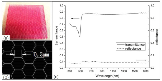
Figure 1.
The halftone coating: (a) a coated glass sample; (b) the details of mesh texture; (c) the spectroscopic test results of coated glass samples.
2.2. Design of Experimental Apparatus
A comparative study of the effect of coating on the thermal behavior of solar collectors was carried out. Therefore, a simplified solar collector was fabricated by dividing the main apparatus evenly into two parts. The difference between the two parts lies in the difference of cover plate.
2.2.1. The Structure of The Solar Collector
The simplified solar collector is composed of a glass cover, a heat absorber plate without fluid flow passage, an insulation layer, and a shell (as shown in Figure 2). The shell with a size of 500 × 800 × 60 mm is assembled by several 1 cm thick PVC plates and separated into two equal parts from the middle by a 1 cm thick PVC plate. The heat absorber plate is made of a 0.2 mm copper plate with black coating on the upper surface. The bottom and surroundings of the shell are equipped with insulation layers. To take infrared images of the inner surface of the cover plate from the back of the collector, an observation window was opened at the middle position of the heat absorber plate, the insulation layer, and the bottom plate of the shell. The size of the observation window is 16 cm × 1 cm in length and width, respectively, corresponding to the field width of the infrared thermography with a focal length of 40 cm. The focal length and window size were determined by several tests, which not only ensured that the infrared image could clearly show the difference of the inner surface temperature between the two halves of the cover plate but also prevented the thermal environment inside the solar collector from being seriously disturbed.
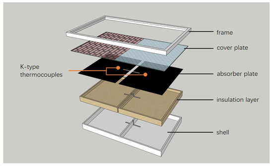
Figure 2.
The structure of the simplified flat plate solar collector.
2.2.2. The Coated Cover Plate
We painted the cover plate in two ways. One method is that half of the cover plate is painted, and half is left blank, with the blank part used as a reference cover plate. The other way is that half of the cover plate is coated on the outer surface and the other half is coated on the inner surface.
2.3. Experimental Scheme
Each half of the solar collector can be considered as an independent solar collector. There are three types for each half of the solar collector to select according to the different cover plate. The type with coating on the outer surface of the cover plate is referred as Type A. The type with coating on the inner surface of the cover plate is referred as Type B. The type with the reference (blank) cover plate is referred as Type R. Three test scenarios based on different combinations of types were set up. Scenario 1 is the combination of Type A and Type R. Scenario 2 is the combination of Type B and Type R. Scenario 3 is the combination of Type A and Type B. The relationship between the scenarios and the types is shown in Figure 3. In the experiment, the thermal behavior of the two parts in the three scenarios were compared.
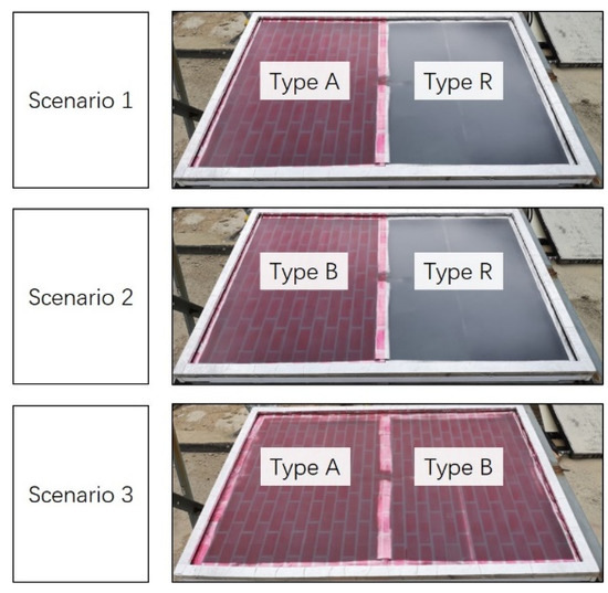
Figure 3.
The relationship between the scenarios and the types.
2.4. Experimental System and Test Method
2.4.1. Experimental System
Except for the solar collector, there are temperature measuring instruments and meteorological data acquisition instruments in the experimental system (as shown in Figure 4). A thermal infrared imager (MAG62, 2% accuracy, Shanghai Magnity Electronics Co., Ltd., Shanghai, China) was used to observe the temperature distribution of cover plates. Two K-type thermocouples (5 TC-TT-K-36-36, precision 0.1, Omega Company, Norwalk, CT, USA) were fixed on the heat absorber plate. Another K-type thermocouple was installed in a thermometer screen to measure ambient temperature. Temperature data were collected by a 4 Channel K thermometer SD Logger (Model 88598, accuracy 0.1, Manufacturer AZ Instrument Corp., Taichung, Taiwan, China). The solar irradiance was measured by a general pyranometer (PSP Serial NO 34329, sensitivity 8.43 μV/W·m2, 300~3000 nm, manufacturer Eppley Laboratory Inc., Newport, RI, USA). Wind speed was measured by an anemometer (DEM6, Tianjin Meteorological Instrument Factory, Tianjin, China).
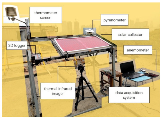
Figure 4.
The experimental apparatus and testing instruments.
2.4.2. Test Method
The infrared thermal image can directly show the surface temperature difference between the two halves of the cover plate. The outer surface temperature of the cover plate can be photographed from the front. The inner surface temperature of the cover plate can be photographed from the back through the observation window (which is closed for non-shooting periods). The heat absorber plate temperature is measured by the K-type thermocouples attached to the back (the location of the thermocouples is shown in Figure 3). After repeated testing of multiple positions, it is proved that the position selected in the experiment can represent the average temperature of the cover plate and heat absorber plate.
3. Analysis of Thermal Network
Thermal network is a schematic of heat transfer, which is helpful to understand heat transfer in a solar collector. In this section, by analyzing the thermal networks of the solar collector with the blank glass cover and coated cover plate, the key variables to be tested and the key issues to be discussed are clarified.
3.1. Thermal Network of Solar Collector without Coating
The cover plate of a solar collector is mainly used to reduce the convective and radiative heat transfer from the heat absorber plate to the external environment. Glass is always selected as the cover plate due to its good optical properties, including high solar radiation transmittance, low absorptance and reflectance, and opaqueness to far infrared radiation. Therefore, the absorption of solar energy in the glass cover is limited, and the effect of absorption on the solar collector is included as the effective transmittance-absorption product according to the empirical relation [30]. However, the solar energy absorbed by the glass cover should not be ignored.
The thermal network for upward heat flow in a single-glazed flat plate solar collector, including the solar energy absorbed by glass cover, is presented in reference [31] (as shown in Figure 5). For a flat plate solar collector, most of the solar radiation reaches the heat absorber plate through the glass cover, which greatly increases the temperature of the heat absorber plate. A small amount of solar radiation is absorbed by the glass cover, slightly increasing the temperature of glass cover. Normally in the heat collecting process, the temperature of the heat absorber plate is higher than the temperature of the cover plate, and the temperature of the cover plate is higher than the ambient temperature. As shown in Figure 5, in the solar collector, heat is transferred from the heat absorber plate to the glass cover by convection and radiation, and outside the solar collector, heat is transferred from the glass cover to the ambient environment by convection and radiation. Under steady-state conditions the energy absorbed by the glass cover plus the heat transferred from the absorber plate to the glass cover is equal to the heat lost from the outer surface of the glass cover to the external environment. The heat balance including the absorption of solar energy by the glass cover, is given by:
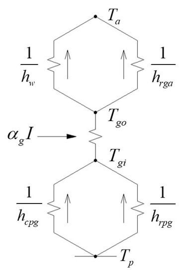
Figure 5.
The thermal network for upward heat flow in a flat plate solar collector including the solar energy absorbed by the glass cover.
Because the absorption of solar radiation in the glass cover has been considered as a case of uniform heat generation, the thermal balance equation on the outer surface of the cover plate is:
The heat balance equation on the inner surface of the cover plate is:
where, is the radiative heat transfer coefficient between the heat absorber plate and the cover plate; is the convective heat transfer coefficient between the heat absorber plate and the cover plate; is the radiative heat transfer coefficient between the cover plate and atmosphere; is the wind heat transfer coefficient. The calculation method of each heat transfer coefficient is given in reference [31,32,33].
3.2. Thermal Network of Solar Collector with Coating
The color-coated cover plate is composed of a glass plate and coating. Because the absorptance of the coating is higher than that of glass, the coating that absorbs solar energy becomes a major heat source for the cover plate. The cover plate is no longer a uniform glass plate, so the thermal network in Figure 5 is no longer applicable to the solar collector with a color-coated cover plate.
Because there are two cases of coating on the outer or inner surface of the cover plate, two thermal networks for upward heat flow of the solar collector with the color coated-cover plate were drawn (as shown in Figure 6). Because the coating is extremely thin, the infrared imager was used to measure the temperature of the coated surface of cover plate. The coating and the coated surface are regarded as a node in the thermal network, which represents a cover plate’s surface temperature. Because of the difference in absorptance and thermal conductivity between the coating and the glass, as well as the existence of patterns, the cover plate is no longer a uniform glass plate. The thermal resistance between the inner surface and outer surface is no longer the ratio of the thermal conductivity of the glass to its thickness, which is expressed as here. For the two thermal networks, under steady-state conditions the energy absorbed by the coating and glass cover plus the heat transferred from the absorber plate to the glass cover is equal to the heat lost from the outer surface of the glass cover to the external environment. The difference is the position of the solar energy absorbed by the coating in the thermal network.
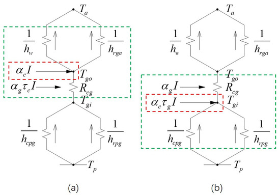
Figure 6.
Thermal network for upward heat flow including solar energy absorbed by the coating and glass cover: (a) coating on the outer surface of the cover plate, (b) coating on the inner surface of the cover plate. The part in the red dotted box is the solar energy absorbed by the coating. The part in the green dotted box is the sketch of energy balance on the coated surface of the cover plate.
It can be seen from Figure 6a that the solar energy absorbed by the coating on the outer surface of the cover plate can increase the outer surface temperature, but its effect on the inner surface temperature is unknown, and vice versa. The effect of the difference in the position of the solar energy absorbed by the coating in the thermal network on the solar collector is also unknown. For solar collectors with blank glass covers, the empirical relations to calculate the inner and outer surface temperature and of the cover plate is given in reference [31] based on the above heat balance equations. For the solar collector with a coated cover plate, the coated cover plate is no longer a uniform glass plate, so the and of the cover plate cannot be calculated by empirical relations. These key values in the thermal network need to be measured. The difference between the effect of the coating on the inner or outer surface of the cover plate on the solar collector also needs to be determined experimentally.
4. Results and Discussion
In this section, a series of infrared images and temperature measurement results obtained from experiments are analyzed and discussed.
4.1. General Effect of Coating on Solar Collector
4.1.1. Increase in The Temperature of Cover Plate
The infrared images shot from the front (Figure 7a) and the back (Figure 7b) in Scenario 1 illustrate that the absorption of solar radiation by the coating increases the temperature of the cover plate. The brick wall pattern on the left half of the cover plate is very clear, as shown Figure 7a. The temperature of the brick part (Pt1: 33.7 °C is significantly higher than that of the brick joint (Pt2: 30.6 °C, whereas the temperature of the brick joint is higher than that of the right half (Pt3: 28.6 °C due to the influence of the temperature of the brick part. It can be seen that the solar energy absorbed by the coating significantly heats the overall outer surface of the left half of the cover plate.
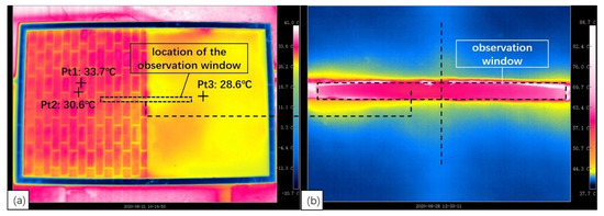
Figure 7.
The infrared images. (a) The infrared image of the solar collector was taken from the front when irradiance was 791 W/m2 and the ambient temperature was 26.9 °C. (b) The infrared image of the solar collector was taken from the back when irradiance was 915 W/m2 and the ambient temperature was 32.9 °C. The dotted box in figure (a) corresponds to the position of the observation window in figure (b).
Although it is difficult to visually compare the temperature of the left and right parts in the observation window (as shown in Figure 7b), the corresponding temperature data in the image show that the inner surface temperature of right half (coated cover plate) is slightly higher than that of the left half (reference cover plate). It indicates that the inner surface temperature of the cover plate is affected by the coating on the outer surface, and the solar energy absorbed by the coating can heat the whole cover plate.
4.1.2. Effect on Energy Collection
Figure 8 shows the absorber plate temperature and the inner and outer surface temperatures of the cover plate when the solar collector was in a short steady state in Scenario 1. Compared with Type R, the heat absorber plate temperature of Type A is lower, but the inner and outer surface temperatures of the cover plate are both higher. It can be seen that the coating on the solar collector increases the cover plate temperature and reduces the heat absorber plate temperature, which is due to the optical properties of the coating. The absorption of visible light by the coating reduces the transmittance of the cover plate, thus increasing the heat absorption of the cover plate and reducing the heat absorption of the heat absorber plate. The decrease in temperature of the heat absorber plate is greater than the increase in temperature of the cover plate. Therefore, this effect is negative for energy collection.
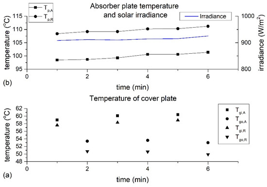
Figure 8.
A short steady state of the solar collector in a heat collecting process when the solar irradiance was about 915 W/m2 and the ambient temperature was 33 °C: (a) the temperature of cover plate; (b) the absorber plate temperature and solar irradiance.
4.2. Effect of Solar Irradiance
The results in the previous section show that the effect of the solar absorption on the coated solar collector and the direct factor that affects the heat absorption of coating is the solar irradiance. During the experimental period, the solar irradiance on sunny days was 800–1000 W/m2, and on cloudy days it was 300–500 W/m2. Figure 9 shows two 15-min heat collecting processes of the solar collector under the conditions of high irradiance and low irradiance in Scenario 1. In each heat collecting process, after initial fluctuations, the solar collector enters a stable heating process basically from the fifth minute. Under low irradiance (as shown in Figure 9a), during the period from 5 to 15 min, the values of and were about 2.2 °C and 0.6 °C, respectively. Under high irradiance (as shown in Figure 9b), during the period from 5 to 15 min, the values of and were about 3.6 °C and 1.1 °C, respectively. It indicates that for Scenario 1, the lower the irradiance, the smaller the values of and .
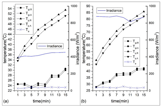
Figure 9.
Temperature change in the heating process: (a) under low solar irradiance; (b) under high solar irradiance.
Figure 10 shows the effect of the change of solar irradiance on the outer surface temperature of the cover plate during a heat collecting process in Scenario 1. It is clear to see that the response of the outer surface temperature of the cover plate to the solar irradiance is rapid. The value of has the same variation trend with solar irradiance, with the maximum being 4.8 °C and the minimum being 0.1 °C. Obviously, when the coating is painted on the outer surface of the cover plate, the effect of solar radiation on the outer surface temperature of the cover plate is very strong.
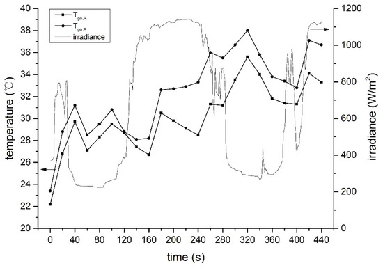
Figure 10.
The change of the outer surface temperature of the cover plate with the fluctuation of solar irradiance.
It can be seen from Figure 9 and Figure 10 that the coating has less of an effect on the heat absorber plate temperature at low irradiance and a greater effect at high irradiance. Because the absorptance of the coating is fixed, the heat absorption of the cover plate is small when the irradiance is low, and the decrease in solar collection due to the low transmittance of the cover plate is reduced as well. When the irradiance is high, the heat absorption of the coating becomes larger, which will obviously increase the temperature of the cover plate, especially the temperature of the coated surface of the cover plate. Therefore, the effect of solar irradiance on the temperature of a coated surface is stronger than that of an uncoated surface. The results measured in Scenario 2 is consistent with that of Scenario 1. Because the inner surface of the cover plate is coated in Scenario 2, the effect of solar irradiance on the inner surface temperature of the cover plate is stronger than that of the outer surface temperature.
4.3. Effect of Different Coating Positions
In both Scenario 1 and 2, the comparison between the coated cover plate and the blank cover plate was performed, and the general effect of the coating on the solar collector was basically the same. But in practice, coating on the outer or inner surface of the cover plate is different, both have their own advantages. The solar collector has a better color effect when the coating is painted on the outer surface of the cover plate. When the coating is painted on the inner surface of the cover plate, the cover plate can protect the coating and extend its service life. How does the coating on different surfaces of the cover plate affect the thermal behavior of the solar collector? The test results in Scenario 1 and 2 did not give an answer. Therefore, we made a direct comparison in Scenario 3.
Test-1 and Test-2 were two 45-min heat collecting processes with similar external climatic conditions in Scenario 3. In the two tests, the solar irradiance and the ambient temperature were very close, and the average wind speed was around 2 m/s. In Test-1, the heat absorber plate temperature and the inner surface temperature of the cover plate were tested, whereas in Test-2, the heat absorber plate temperature and the outer surface temperature of the cover plate were tested. In the 35–45 min of the two tests, although the cover plate temperature changed due to the influence of the external environment, the heat absorber plate temperature remained basically stable. For the 35–45 min in Test-1, the value of was about 0.6 °C (Figure 11a), and the value of was about 1.0 °C (Figure 11b). For the 35–45 min in Test-2, the value of was about 0.8 °C (Figure 11c), and the value of was about 1.6 °C (Figure 11d).
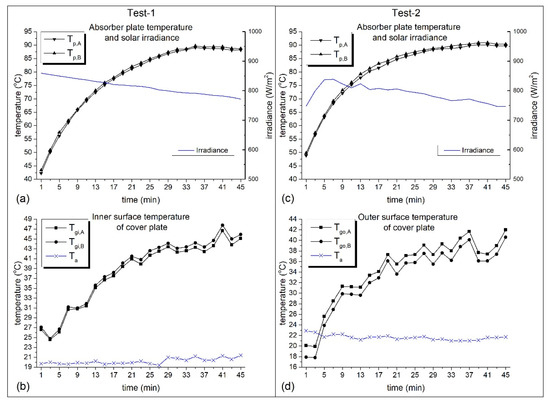
Figure 11.
Temperatures in the two heat collecting processes: (a) the absorber plate temperature in Test-1; (b) the inner surface temperature of cover plate in Test-1; (c) the absorber plate temperature in Test-2; (d) the outer surface temperature of cover plate in Test-2.
From the tests in Scenario 1 and Scenario 2, the different transmittance of the cover plates caused the absorber plate temperature difference between the two parts, and the different absorptance of the cover plates caused the cover plate temperature difference between the two parts. For Scenario 3, both the transmittance and absorptance of cover plate of the two parts are the same, so the heat absorber plate temperature difference and the cover plate temperature difference between the two parts are determined by the difference of the position of the coating.
According to the analysis in Section 3.2, the two heat networks are generally similar (as shown in Figure 6), but the coatings on different surfaces of the cover plate participate in different heat transfer processes. When the coating is on the outer surface of the cover plate, under steady-state conditions part of the solar energy absorbed by the glass and the solar energy absorbed by the coating plus the heat conducted from the inner surface to the outer surface of the cover plate is equal to the heat lost from the outer surface of the cover plate to the atmosphere (as shown in the green dotted box in Figure 6a). The energy absorbed by the coating increases the heat lost from the outer surface of the cover plate to the atmosphere due to the exposure of the coating in the atmosphere (as shown in Figure 12a). When the coating is on the inner surface of the cover plate, under steady-state conditions part of the solar energy absorbed by the glass and the solar energy absorbed by the coating plus the energy transferred from the absorber plate to the cover plate is equal to the heat conducted from the inner surface to the outer surface of the cover plate (as shown in the green dotted box in Figure 6b). The solar energy absorbed by the coating is retained in the solar collector due to the insulation of the cover plate, which compensates for the energy loss caused by the low transmittance (relative to the blank glass plate) of the cover plate to some extent (as shown in Figure 12b).
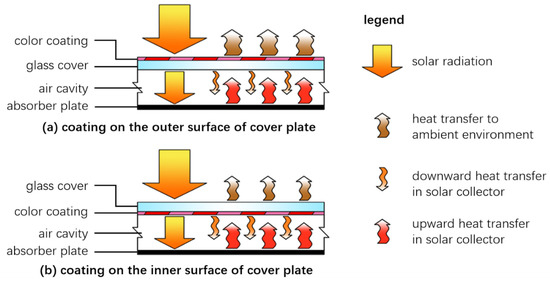
Figure 12.
Heat transfer diagram of a solar collector: (a) coating on the outer surface of cover plate; (b) coating on the inner surface of cover plate.
The heat transfer from the heat absorber plate to the inner surface of the cover plate (referred as ) and the heat lost from the outer surface of the cover plate to the atmosphere (referred as ) are the two processes of the heat loss from the absorber plate to the atmosphere through the cover plate. and were calculated according to the temperatures tested and the calculation method provided in reference [31,32,33]. Figure 13 shows the and values of the two parts in the 35–45 min of the two tests. In Test-1, was slightly less than , and the difference between them was less than 1% of . In Test-2, was 4% to 5% smaller than . It indicates that the heat transfer from the heat absorber plate to the cover plate of the two parts are almost the same, whereas the heat lost from the cover plate of Type B to the atmosphere is significantly less than that of Type A. From the comparison results, the coating on the inner surface of the cover plate did not significantly reduce the heat transfer from the heat absorber plate to the cover plate, but the energy absorbed by the coating increased the heat absorber plate temperature. In contrast, the coating on the outer surface of the cover significantly increased the top heat loss (heat lost from the cover plate to the atmosphere) of the solar collector. Because the transmittance of the two parts of the cover plate are the same, the amount of solar radiation received by the two parts of the heat absorber plate are the same. The shell of the solar collector has a good thermal insulation performance, and the heat collected by the solar collector is mainly lost through the cover plate. Therefore, the Type B with less heat loss can obtain more useful energy, to obtain a higher heat absorber plate temperature. As a result, under the premise of a certain transmittance of the cover plate, coating on the inner surface of the cover plate is better than coating on the outer surface of the cover plate for improving the heat collection of the solar collector and increasing the useful energy.
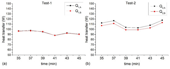
Figure 13.
Heat transfer at each time point in the two tests: (a) Q1 in Test-1; (b) Q2 in Test-2.
5. Conclusions
The effects of the coating of the cover plate on the thermal behavior of the solar collector under different conditions are summarized as follows:
(1) The color coating reduces the transmittance of the cover plate and increases the absorptance of the cover plate, thus reducing the heat absorber plate temperature and increasing the cover plate temperature.
(2) The coating has a smaller effect on the solar collector under low solar irradiance. The effect of solar irradiance on the coated surface temperature of the cover plate is stronger than the effect on the uncoated surface temperature.
(3) The solar energy absorbed by the coating changes the upward heat transfer of the solar collector. When the coating is on the outer surface, most of the solar energy absorbed by the coating is lost directly. When the coating is on the inner surface, part of the solar energy absorbed by the coating is retained, which reduces the top heat loss of the solar collector, thus increasing the useful energy gain and the heat absorber plate temperature. In the two tests under similar external climatic conditions, compared with the solar collector with coating on the outer surface of the cover plate, the one with coating on the inner surface has 0.8 °C higher heat absorber plate temperature and 5% less top heat loss.
Future research should consider the effect of other factors on the solar collector with color coating on the cover plate as well as the color effect of the solar collector in the case of coating on different surfaces of the cover plate. The study on improving the appearance of PV panels by artistic treatment of PV glass is also under consideration.
Author Contributions
Conceptualization, Y.W.; methodology, C.L.; software, C.L.; validation, C.L. and Q.H.; formal analysis, C.L.; investigation, C.L.; resources, Y.W.; data curation, C.L.; writing—original draft preparation, C.L.; writing—review and editing, Q.H. and C.L.; visualization, C.L.; supervision, Q.H.; project administration, Q.H.; funding acquisition, Y.W. All authors have read and agreed to the published version of the manuscript.
Funding
This research received no external funding.
Acknowledgments
Research assistance by Yong Sun and Yuanzhi Gao on earlier versions of this manuscript is gratefully acknowledged.
Conflicts of Interest
The authors declare no conflict of interest.
Nomenclature
| transmittance of glass plate | |
| transmittance of coating | |
| absorptance of glass plate | |
| absorptance of coating | |
| solar irradiance projected onto the collector | |
| radiative heat transfer coefficient between the heat absorber plate and the cover plate | |
| convective heat transfer coefficient between the heat absorber plate and the cover plate | |
| radiative heat transfer coefficient between the cover plate and atmosphere | |
| wind heat transfer coefficient | |
| heat conductivity of glass plate | |
| thickness of glass plate | |
| thermal resistance of coated glass plate | |
| inner surface temperature of cover plate | |
| outer surface temperature of cover plate | |
| heat absorber plate temperature | |
| ambient temperature | |
| Subscript | |
| A | Type A |
| B | Type B |
| R | Type R |
References
- Liu, G.; Tan, Y.; Li, X. China’s Policies of Building Green Retrofit: A State-Of-The-Art Overview. Build Environ. 2020, 169, 106554.1–106544.8. [Google Scholar] [CrossRef]
- Zhang, W.; Zhang, Y.; Li, Z. A Rapid Evaluation Method of Existing Building Applied Photovoltaic (BAPV) Potential. Energy Build. 2017, 135, 39–49. [Google Scholar] [CrossRef]
- Jung, S.; Huh, J.H. Demand Response Resource Energy Optimization System for Residential Buildings: Smart Grid Approach: MUE/FutureTech 2018. In Advanced Multimedia and Ubiquitous Engineering; James, J., Park, J.H., Chen, S.-C., Eds.; Springer: Singapore, 2018; pp. 517–522. [Google Scholar]
- Ko, J.S.; Huh, J.H.; Kim, J.C. Overview of Maximum Power Point Tracking Methods for PV System in Micro Grid. Electronics 2020, 9, 816. [Google Scholar] [CrossRef]
- Jung, S.; Huh, J.H.; Park, J. A Study on Acer Mono Sap Integration Management System Based on Energy Harvesting Electric Device and Sap Big Data Analysis Model. Electronics 2020, 9, 1979. [Google Scholar] [CrossRef]
- Cristofari, C.; Notton, G.; Canaletti, J.L. Thermal behavior of a copolymer PV/Th solar system in low flow rate conditions. Sol. Energy 2009, 83, 1123–1138. [Google Scholar] [CrossRef]
- Maurer, C.; Cappel, C.; Kuhn, T.E. Progress in Building-Integrated Solar Thermal Systems. Sol. Energy 2017, 154, 158–186. [Google Scholar] [CrossRef]
- Kalogirou, S.A. Building Integration of Solar Renewable Energy Systems towards Zero or Nearly Zero Energy Buildings. Int. J. Low-Carbon Technol. 2015, 10, 379–385. [Google Scholar] [CrossRef]
- Quesada, G.; Rousse, D.; Dutil, Y. A Comprehensive Review of Solar Facades. Opaque Solar Facades. Renew. Sustain. Energy Rev. 2012, 16, 2820–2832. [Google Scholar] [CrossRef]
- Quesada, G.; Rousse, D.; Dutil, Y. A Comprehensive Review of Solar Facades. Transparent and Translucent Solar Facades. Renew. Sustain. Energy Rev. 2012, 16, 2643–2651. [Google Scholar] [CrossRef]
- Munari, P.M.; Roecker, C. Towards an Improved Architectural Quality of Building Integrated Solar Thermal Systems (BIST). Sol. Energy 2007, 81, 1104–1116. [Google Scholar] [CrossRef]
- Cappel, C.; Streicher, W.; Lichtblau, F. Barriers to the Market Penetration of Façade-Integrated Solar Thermal Systems. Energy Procedia 2014, 48, 1336–1344. [Google Scholar] [CrossRef]
- Crnjakorel, Z. Spectrally Selective Solar Absorbers in Different Non-Black Colours. Sol. Energy Mater. Sol. Cells 2004, 85, 41–50. [Google Scholar] [CrossRef]
- Anderson, T.N.; Duke, M.; Carson, J.K. The Effect of Colour on the Thermal Performance of Building Integrated Solar Collectors. Sol. Energy Mater. Sol. Cells 2010, 94, 350–354. [Google Scholar] [CrossRef]
- Kalogirou, S.; Tripanagnostopoulos, Y.; Souliotis, M. Performance of Solar Systems Employing Collectors with Colored Absorber. Energy Build. 2005, 37, 824–835. [Google Scholar] [CrossRef]
- Bonhôte, P.; Eperon, Y.; Renaud, P. Unglazed Coloured Solar Absorbers on Façade: Modelling and Performance Evaluation. Sol. Energy 2009, 83, 799–811. [Google Scholar] [CrossRef]
- Fekete, I.; Farkas, I. Numerical and Experimental Study of Building Integrated Solar Tile Collectors. Renew. Energy 2019, 137, 45–55. [Google Scholar] [CrossRef]
- Bingqing, L.; Zhongting, H.; Xiaoqiang, H. Experimental study of the water heating performance of a novel tile-shaped dual-function solar collector. Energy Procedia 2015, 70, 87–94. [Google Scholar]
- Zhongting, H.; Bingqing, L.; Wei, H. Performance study of a dual-function roof solar collector for Chinese traditional buildings application. Appl. Therm. Eng. 2018, 128, 179–188. [Google Scholar]
- Schüler, A.; Roecker, C.; Scartezzini, J.L. On the Feasibility of Colored Glazed Thermal Solar Collectors Based On Thin Film Interference Filters. Sol. Energy Mater. Sol. Cells 2004, 84, 241–254. [Google Scholar] [CrossRef]
- Schuler, A.; Boudaden, J.; Oelhafen, P. Thin Film Multilayer Design Types for Colored Glazed Thermal Solar Collectors. Sol. Energy Mater. Sol. Cells 2005, 89, 219–231. [Google Scholar] [CrossRef]
- Boudaden, J.; Ho, S.C.; Oelhafen, P. Towards coloured glazed thermal solar collectors. Sol. Energy Mater. Sol. Cells 2004, 84, 225–239. [Google Scholar] [CrossRef]
- Mertin, S.; Hody-Le, C.V.; Joly, M. Reactively Sputtered Coatings on Architectural Glazing for Coloured Active Solar Thermal Façades. Energy Build. 2014, 68, 764–770. [Google Scholar] [CrossRef]
- Jolissaint, N.; Hanbali, R.; Hadorn, J. Colored Solar Façades for Buildings. Energy Procedia 2017, 122, 175–180. [Google Scholar] [CrossRef]
- Alvarez, A.; Cabeza, O.; Muniz, M.C. Experimental and numerical investigation of a flat-plate solar collector. Energy 2010, 35, 3707–3716. [Google Scholar] [CrossRef]
- Fan, J.; Furbo, S. Buoyancy Effects on Thermal Behavior of a Flat-Plate Solar Collector. J. Sol. Energy Eng. 2008, 130, 247–266. [Google Scholar] [CrossRef]
- Said, Z.; Sajid, M.H.; Alim, M.A. Experimental investigation of the thermophysical properties of AL2O3-nanofluid and its effect on a flat plate solar collector. Int. Commun. Heat Mass Transf. 2013, 48, 99–107. [Google Scholar] [CrossRef]
- Yang, L.; Lenz, R.; Kruse, B. Light scattering and ink penetration effects on tone reproduction. J. Opt. Soc. Am. A Opt. Image Sci. Vis. 2001, 18, 360–366. [Google Scholar] [CrossRef][Green Version]
- Clapper, F.R.; Yule, A.C. The Effect of Multiple Internal Reflections on the Densities of Half-tone Prints on Paper. J. Opt. Soc. Am. 1953, 43, 600–603. [Google Scholar] [CrossRef]
- Tianhong, D.; Zhu, Z. The Calculations of The Effective Transmittance-absorptance Product of Flat Plate Solar Air Collectors. Acta Energ. Sol. Sin. 1996, 17, 303–307. [Google Scholar]
- Akhtar, N.; Mullick, S.C. Effect of Absorption of Solar Radiation in Glass-Cover(S) On Heat Transfer Coefficients in Upward Heat Flow in Single and Double Glazed Flat-Plate Collectors. Int. J. Heat Mass Transf. 2012, 55, 125–132. [Google Scholar] [CrossRef]
- Hollands, K.G.T.; Unny, T.E.; Raithby, G.D. Free convective heat transfer across inclined air layers. ASME J. Heat Transf. 1976, 98, 89–192. [Google Scholar] [CrossRef]
- Buchberg, H.; Catton, I.; Ewards, D.K. Natural convection in enclosed spaces–a review of application to solar energy collection. ASME J. Heat Transf. 1976, 98, 182–188. [Google Scholar] [CrossRef]


Publisher’s Note: MDPI stays neutral with regard to jurisdictional claims in published maps and institutional affiliations. |
© 2020 by the authors. Licensee MDPI, Basel, Switzerland. This article is an open access article distributed under the terms and conditions of the Creative Commons Attribution (CC BY) license (http://creativecommons.org/licenses/by/4.0/).