1. Introduction
Building an industrial-scale modern plant intended for plastic waste recycling and meeting the current requirements of Poland’s and the EU’s law while operating efficiently and reliably and being economically profitable is a major challenge. In recent years, there have been many publications on plastic processing technologies and the related processes, based inter alia on thermal cracking and (catalytic and non-catalytic) pyrolysis [
1,
2,
3], including depolymerization [
4,
5], hydrocracking or co-pyrolysis processes [
6,
7]. The possibilities of removing organic and inorganic impurities in recycled polyolefin polymers were also investigated by Yao et al. [
8]. Value-added products for furfural residue conversion are described in detail in the fields of soil culture, catalytic hydrolysis, thermal decomposition and porous adsorption in [
9]. Moreover, review papers describing directions of development and feasibility studies on polymer recycling technologies (both mechanical and chemical), in relation to dominant technologies in the current industrial reality, have been published lately by Ragaert et al. [
10], Lange and Ferreira [
11], Mastellone [
12], Awaja and Pavel [
13] and Uzoejinwa et al. [
14]. Such works dominate in this particular research area.
However, most of these papers have one common feature: they describe research on a laboratory or a quarter-industrial scale. Other papers describe certain trends, opportunities and feasibility studies on creating an industrial-scale plant. Only a few studies describing real full-scale plants and systems with proven profitability have appeared lately [
10,
15], and the latest is [
16]. The authors of these studies present analyses of various recycling technologies supported by examples of plants operating different technologies, e.g., Siemens-KWU and Mogami-Kiko Japan (thermal pyrolysis), Lurgi-SVZ Germany (gasification), Fuji Japan (catalytic cracking) or Böhlen (hydrocracking). Unfortunately, just a few of these technologies have found professional industrial application in Poland.
One example is the Agrob-Eko company from Zabrze, founded in 1997. In 2000–2003, it built a plant with a technological line for processing polyolefin waste plastics to make components that could then be used for the production of fuels and heating oils. The technological process and some of the devices have been patented by the company, in collaboration with scientific institutions. The company operates a plant for catalytic processing of waste by sorting, homogenization at 250 °C and thermal cracking at 400 °C. The wide KTS–F (
pol.: Komponent z Tworzyw Sztucznych-Frakcje, component of plastics—fractions) fraction obtained in this way is subjected to atmospheric and vacuum distillation followed by a hydro-treatment process (catalytic hydrogenation) and zeoforming (gasoline) [
17]. In this way, the company can offer semi-finished hydrocarbon products for further processing as well as ready-to-use fuel components and fuels that meet the quality requirements of Polish standards. Agrob-Eko had also planned to build a second, more modern plant in Kędzierzyn-Koźle in the industrial zone chemical plants, but this investment has not been completed. Another example is the EKONAKS company seated in Skarżysko-Kamienna. This company processes polyolefin plastics using the catalytic cracking technology in a rotary close-batch reactor. In the process of the KTS–F fraction flow through the liquefaction system, three hydrocarbon fractions are obtained—the gaseous fraction, heavy oils and light oils—which are then utilized for the purposes of the plant’s technology and which are suitable as components for further processing [
18]. The plant also sells the wide KTS–F hydrocarbon fraction (CN 3811).
This paper presents the design and operation of a Polish packaging-waste recycling plant owned by the GreenTech Poland company. The plant carries out industrial-scale chemical and thermal processing of waste plastics from the polyolefin group as a particular type of non-catalytic thermal cracking, herein referred to as non-catalytic (degradative) depolymerization. The paper focuses on the plant technical aspects, detailing the level of sophistication of technical solutions in devices and systems and focusing also on compliance with binding regulations.
2. Description of the Plant Operation and Technology
The plant works in a single- and multi-shift system. The main goal of the plant activity is the mechanical and chemical processing of wastes coming from selective waste collection and post-production facilities. The plant obtained an integrated permit to collect and process waste in Poland in accordance with national regulations, listed in
Table 1.
The products obtained in the plant are:
- -
sorted wastes,
- -
liquid and gaseous products resulting from chemical processes, and
- -
electricity and thermal energy.
The sources of the plant financial income are:
- -
revenues from fees for the receipt and processing of wastes (recycling fees),
- -
revenues from the sale of electricity to the public grid,
- -
revenues from the sale of liquid hydrocarbon products obtained in chemical processes, and
- -
revenues from the sale of certain sorted waste, e.g., PET.
The plant is designed to receive and process waste amounting to 50 tons/day. Part of this mass stream is waste sorted mechanically at the sorting stage. The rest (about 20 to 30 tons/day) is fed into the degradative depolymerization system. This relatively wide range of fluctuations in the waste stream results from the fact that the composition and content of various substances in the waste mass vary considerably and constant ranges are difficult to maintain.
The plant follows proper waste management procedures, including waste records and quantities of processed waste, in accordance with regulations and obtained permits. The plant does not process hazardous waste in accordance with the regulations and the decision on environmental conditions as above.
Waste processing in the plant consists of receiving, unloading and storage, mechanical separation (sorting), feeding the selected part into the degradative depolymerization system and chemical processing into liquid and solid fractions, which—after more treatment processes—can be used as fuel or sold as excise energy goods.
Wastes are delivered to the plant by road; they are recorded, weighed and unloaded in the warehouse area. The wastes are delivered in the form of cubic or rectangular bales with limit dimensions of 1200 × 1100 × 750 mm and weights from 200 to 700 kg. Wastes can also be delivered in the form of loosely loaded mass with a bulk density of 40 to 60 kg/m3. Cars are unloaded using forklifts and manually (removal of residual wastes from car holds). The storage space enables raw material storage lasting for a week of the technological system operation. This ensures operational stability and technological safety (a sudden stoppage of the raw material supply into the depolymerization system might cause negative effects).
The wastes are then systematically taken from the warehouse and transported by forklift or manually to the adjacent room, where they are fed onto the sorting line, as presented in
Figure 1. The beginning of the line is the belt conveyor, which transports the wastes to another conveyor and then to more devices of the sorting line. The devices are listed in
Table 2 according to the direction of the sorting process.
The sorted and finally shredded wastes are directed to the first of two steel buffer silos with a capacity of 340 m3. The wastes are packaging and other products made of plastic, in which the main component is one of the three synthetic polymers from the polyolefin group: polypropylene, polyethylene and polystyrene. The waste generally has the shape of flakes with average dimensions of 25 × 25 mm or larger, a thickness ≤ 3 mm and a water content of up to 25%. The silo has an internal waste loosening system using nozzles fed with compressed air from the compressors room, which is described in more detail below. The waste is systematically taken from the bottom of the silo and transported to the granulator.
Here, in the homogenization and cooling process, the waste volume is reduced and the water content is decreased to ≤10%. After leaving the granulator, the wastes are directed to another steel tank: the dry raw material silo with a capacity of 540 m3. This silo is also equipped with a compressed air loosening system. From there onwards, the waste is recognized as the raw material for the depolymerization line.
Materials sorted or rejected on the line are transported to separate containers located outside the building under a roof. The stream of rejected waste mainly includes ferrous and non-ferrous metals, paper (cellulose), glass (full undamaged packaging and cullet) and plastics (mainly PVC, PET, PTFE, PA, PVDF, composites and others). These wastes are transported by belt conveyors in a direction perpendicular to the main waste transfer direction of the sorting line:
Paper, metals and selected materials are additionally subjected to the pressing process with the use of devices intended for this purpose: a press intended for non-ferrous metals, mainly aluminum (Al) alloy packaging, and a second intended for paper, including cardboard and cellulose products, as well as for sorted plastics, e.g., packaging made of PET (polyethylene terephthalate).
The above-mentioned wastes are then loaded onto vehicles, weighed, recorded and exported outside the plant for sale.
The sorting line is equipped with an auxiliary dust-removal system, which consists of the filter assembly as well as a system of pipelines and fittings connecting the filter to selected devices of the line where dust appears. Air with dust particles (aerosol) is sucked in by overlaps installed above the devices, from where, due to negative pressure induced by the fan, it flows through the pipelines to the filter. In the filter assembly, the air is purified and directed to the discharge chimney. Dust is systematically collected from the container located at the bottom of the filter body. The filter is a vertical tank structure with a nominal capacity of 13,000 m3/h equipped with internal cylindrical filter cartridges and cleaned periodically in the process of the reverse compressed-air flow. Cleaning is triggered automatically the moment that the set pressure difference threshold, measured before and after the filter cartridges, is exceeded. Compressed air is supplied from the compressor room.
The maximum theoretical efficiency of the sorting line, i.e., the waste-sorting capacity, is about 80 m3/h i.e. 4000 kg/h. The proper part of polyolefin wastes intended for the depolymerization process is not less than 90% of the total mass stream of waste entering the sorting line, after treatment and homogenization (of water content ≤ 10%). Additionally, there are losses in the waste stream (due to incorrect sorting, rejection of small items), which amount to 1% to 5% of the mass flow. Thus, the minimum overall capacity of the sorting line, based on the produced raw material, totals at least 2000 kg/hThe assumed maximum overall capacity is 4000 kg/h.
It should be noted that none of the plants mentioned above has such a well-developed sorting line enabling polyolefin selection and making it possible to handle wastes coming from various sources. A lack of a sorting line involves the need to select waste at the supplier’s site (which is not always possible), as well as risks created by feeding unsuitable waste into the process, e.g., waste made of PVC, PTFE or PA, which might compromise the safety of technological processes or damage the system.
3. Degradative Depolymerization System
The plant was originally designed in three stages: in the chemical design, where reactions and processes taking place in the R101 reactor and the R201 extractor are described; in the process (technological) design, describing momentum, heat and mass transfer processes and specifying limit values for individual process operations together with principal assumptions for the system devices, i.e., dimensions, geometry, equipment, heat and mass transfer surfaces and the demand for energy and utilities; and in the mechanical design, comprising working documentation of devices, pipelines and guidelines for market suppliers [
19]. The remaining part of the depolymerization line at the GreenTech packaging waste recycling plant in Toruń is presented in
Figure 2.
The degradative depolymerization system, i.e., the technological system intended for chemical processing of packaging and multilayer waste, constructed under the umbrella roof of the depolymerization unit, is composed of several process modules:
- -
extractor unit with systems and related equipment,
- -
reactor unit with related systems and devices,
- -
cooling and fractionation system with intermediate tanks,
- -
heating and cooling systems,
- -
system for storage and preparation of products to be supplied to power generators or pumped into road tankers,
- -
LPG (propane) supply system,
- -
systems for production and distribution of compressed air and nitrogen,
- -
power generator units with cogeneration modules and related systems for generation and transmission of electricity.
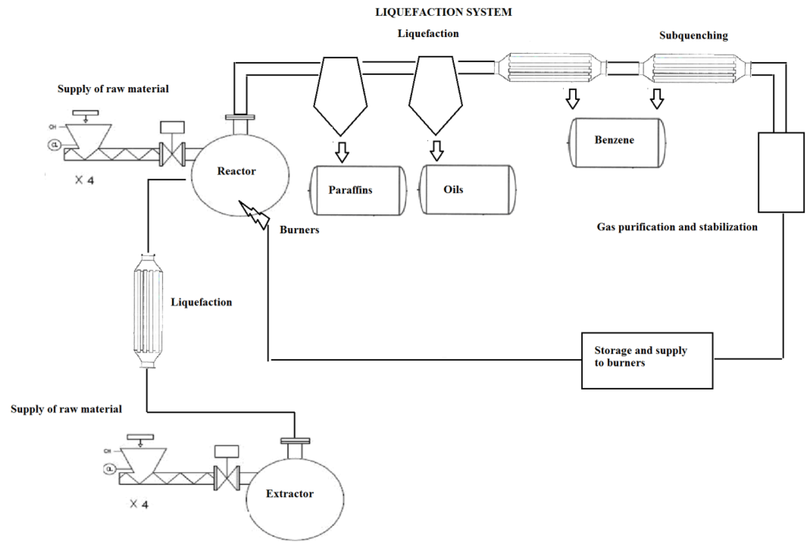
For comparison, the schematic diagram of the Agrob-Eko company system is similar but based on a different technology. It is presented in
Figure 3.
In this case, having gone through the sorting line, the raw material is subjected to homogenization and depolymerization like in the Toruń plant. Here, however, tank mixers are used for this purpose. This involves the need to pause the process at certain intervals to clean the inside of the tanks of accumulated contaminants. Further on, there are heaters and distillation and rectification columns. Fractionated products, gasoline, oils and heavy fractions (mazout) are obtained. The application of a system of columns makes it possible to achieve specific properties of the product, but as deposits of impurities/contaminants are not effectively removed earlier, the plates of the columns get clogged and need systematic cleaning. The packaging waste recycling plant in Toruń is free from such problems. The issue of the removal of contaminants was solved successfully. At the same time, the system intended for the separation of fractions was simplified.
All devices and systems were made and launched into the market according to the EU’s requirements and in compliance with harmonized standards (EN) or other recognized guidelines.
The process makes use of a novel technology of chemical processing of waste through non-catalytic thermal cracking and multi-stage liquefaction of the stream of vapors and cooling of liquids resulting therefrom. The applied devices and utilized technologies are partly protected by patents for inventions, e.g., [
20,
21,
22,
23]. The advantage of the solution is that the process does not include a catalyst. Owing to that, there is no erosion of walls of pipelines or other devices, including rotors and pump sealing, which is a common phenomenon observed e.g., in the Agrob-Eko plant. There is also no issue of worn-out catalyst disposal. Another good aspect is that the system operating costs are lower with this solution.
The system’s theoretical maximum efficiency totals 1500 kg/h. Several processes are realized in it simultaneously:
- -
extraction (homogenization) of the raw material mass, i.e., dissolution of the waste mass in liquid medium hydrocarbon and oil fractions acting as a solvent in the temperature from 150 to 200 °C realized in the extractor unit and in the system and the system auxiliary devices;
- -
depolymerization, realized in the temperatures from 380 to 400 °C in the reactor unit and in the system and the system auxiliary devices;
- -
cooling and fractionation of depolymerization products in assemblies of the membrane and non-membrane heat exchangers, in the cooling and in the refrigeration system, in intermediate tanks and in auxiliary devices;
- -
storage and transport of heat, realized in membrane heat exchangers (recuperators) and in the system and the system auxiliary devices;
- -
storage and preparation of products to be supplied into power generators or pumped into road tankers, realized in a relevant system intended for that purpose.
The line also includes a system for the production and distribution of compressed air and nitrogen used to make the inside of the depolymerization line inert.
3.1. Feeding the Depolymerization Line with the Raw Material
Crushed raw material is transported from the dry raw material silo using a PLW 600/16,000 conveyor belt (described above). Next, passing through an electric shaker assembly, it is fed into a carousel system of four screw conveyors spreading the material horizontally and supplying it gravitationally to fill-and-feed systems connected to assemblies of screw presses. The systems have a built-in device pushing crushed raw material to the screw presses. The device is driven indirectly through the presses. Charging hoppers are equipped with level sensors controlling the operation of the horizontal conveyors. The screw presses feed the raw material into the tank of the R101 reactor and the 201 extractor in the form of a compressed mass of plastics in a cylinder-like shape (the effect of forcing the mass through charging connector pipes). At the same time, the mass cuts off the inside of the apparatus from the environment. The raw material can also be supplied on the path between the R201 extractor and the R101 reactor in the form of a liquid solution of polyolefins (homogenization product) prepared in the extractor earlier. Fragments of simplified schematic diagrams and isometric views are presented below in
Figure 4.
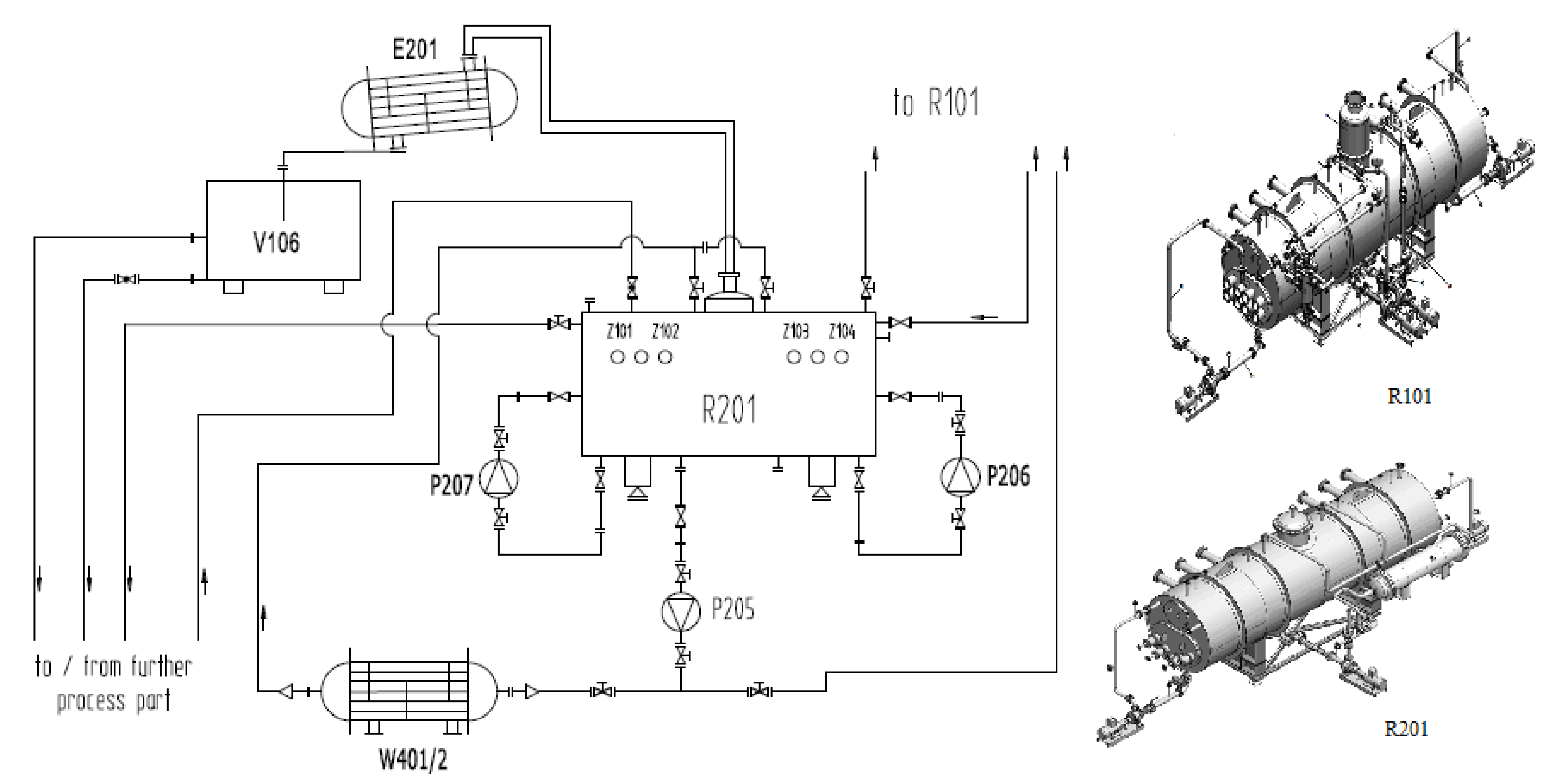
3.2. Extractor Unit with Auxiliary Equipment (Systems and Devices)
The R201 extractor is a lying tank with flat bottoms with an operating space capacity of about 30 m3. On its side surface, there are six connector pipes to enable connection to the screw presses feeding the material. The extractor also has a number of other connector pipes to connect co-operating devices, e.g., circulation pumps and measuring instruments ensuring the process control. It is based on a ramp and an assembly of tensometric scales, which enables continuous control of the extractor filling level.
3.3. Extractor R201 Charging System
Raw material is fed into the extractor using four screw extruders (screw presses)—Z101 to Z104 (GreenTech Polska, 2020). The presses are adapted for operation on the worst raw material, i.e., materials with the lowest bulk density. The feeding screw conveyors can be stopped one by one, e.g., if the extraction solution concentration rises or if the process output needs to be reduced. The heating/cooling system of the screw body makes it possible to create a “plug” separating the extractor gaseous space from the atmosphere. The screw feeder is connected to the extractor by a (normally closed) scissors gate driven pneumatically. Owing to that, it can be stopped safely.
3.4. System Feeding the Solvent to the Extractor
The extraction process needs a continuous supply of the solvent to the extractor. The extraction solvent is the heavy fraction obtained from the liquefaction of the reactor products. The solvent sources are intermediate tanks V104 and V107 of heavy fractions. The fraction is fed through a pipeline equipped with pump P104 and automatic valves for flow control.
3.5. Extractor Heating
The extraction mixture has to be heated to maintain the homogenization process temperature (in the range from 180 to 200 °C); this is done using a system of membrane heat exchangers, including the E202/W401 shell-and-tube heat exchanger on the pipeline transporting pure solvent, and two tube-in-tube exchangers in the extractor by-pass cycles. The heating medium is thermal oil flowing in a closed cycle. Heated thermal oil flows through the plate exchanger first and then passes to in-series exchangers in the extractor by-pass cycles (through the first and then through the second). There is also an additional by-pass of the plate exchanger to provide for a situation where the solvent transported to the extractor is not pure enough. The system protects the exchanger against the creation of vapors due to the heating medium temperature being higher than the solvent boiling point. The heat transferred to the extraction mixture is taken from the co-generation system; heat is recovered from combustion gases from the R101 reactor gas burners through an in-series system of eight exchangers and section shell-and-tube exchangers of combustion gases from power generators. Technologically, the method of the extraction mixture heating is twofold:
- -
giving up heat by the heated pure solvent to achieve a temperature higher than the temperature in the extractor as the solvent is mixed with the extraction solution (feeding)—E202/W401 shell-and-tube heat exchanger;
- -
transferring the thermal oil heat to the extraction mixture based on the principle of the heat transfer—exchangers in the by-pass cycles.
3.6. Mixing the Extractor Content
Three circulation pumps of the extraction mixture (P205, P206 and P207) are installed under the extractor. Their task is to improve the process conditions (accelerate the dissolution of polyolefins and enhance the heat transfer between heating elements and the mixture). They are modified open-impeller pumps with a discharge of up to 30 m3/h, the delivery head reaching 30 m of the liquid column and the power of 5.5 kWe. This gives the total discharge value of up to 90 m3/h, which makes it possible to exchange the extraction mass 4.5 times per hour (the extractor working filling level is 2/3 of the working capacity). The heavy fraction mixture with crushed material is taken from the tank’s lower connector pipes located in the tank’s middle part. The pumps mentioned above direct it to the connector pipes on the reactor side surface.
3.7. Liquefaction System for Gaseous Products of Extraction
The thermal conditions in the R201 reactor involve evaporation of the raw material moisture and of the trace amount of the light fraction that may be contained in the solvent. The vapors are condensed in the E201 heat exchanger. The liquid is then directed to the V106 tank acting as the separator of liquefied fractions. The vapors emitted in extractor R201 are cooled, condensed and captured in the tank (the separator), where the water fraction is separated from hydrocarbons.
3.8. System Removing Contaminants and Feeding the Extraction Mixture into the Reactor
The extraction mass is taken from extractor R201 by the P205 pump. Using a control valve, the extraction mass is fed continuously through the F103 filter to the R101 reactor of the depolymerization process. The degree of the valve opening depends on the rate at which the mass in the reactor decreases.
3.9. F103 Filter
The contaminants are removed using a slit filter with an automated removal of deposits. The filter structure enables continuous operation; the discharge of deposits does not cause stoppages of the process. The obtained amount of contaminants in the extraction mass totals about 20%. The contaminants are dumped onto a separating slit filter equipped with an arc slot-sieve (FOTI type – Filtration Outside To Inside), where the remains of the liquid are drained and washed with pure solvent. The purified liquid accumulated on the separator bottom is pumped back into the extractor using pump P105.
3.10. Reactor Unit with Auxiliary Equipment (Systems and Devices)
The R101 reactor is a lying tank with flat, ribbed bottoms made of austenitic steel with an operating space capacity of about 30 m
3, filled on average to 2/3 of this value, i.e., to about 20 m
3. The raw material is fed into the reactor using four screw conveyors: Z105 to Z108. The system is adapted for operation on the worst raw material, i.e., the material with the lowest bulk density. The feeding screw conveyors can be stopped one by one, e.g., if the reaction mixture level rises or if the process output needs to be reduced. The heating/cooling system of the screw body makes it possible to create a “plug” separating the reactor gaseous space from the atmosphere. The screw feeder is connected to the reactor by a (normally closed—self-closing) scissors gate driven pneumatically. Owing to that, it can be stopped safely. The heating elements are embedded within the reactor tank bottom. The reactor also has a number of connector pipes to connect co-operating devices, e.g., circulation pumps and measuring instruments ensuring control of the reaction process. The K101 hydraulic column valve, filled with a barrier liquid to reduce the reactor pressure if it rises above the permissible value, is connected to the vapor-vent pipe mounted on the reactor chimney. The R101 reactor is based on tensometric scales, which enables continuous control of the reactor filling level [
19].
3.11. Feeding Extraction Mass into the Reactor
The extraction mass is fed into the reactor connector pipe from extractor R201 using the P205 pump. The amount of the extract depends on the process rate and it is filled in systematically to ensure the appropriate level of extraction mass in the reactor.
3.12. Reactor Heating
The heating elements are embedded in the reactor flat bottoms on both sides in the form of profile tubes to which burners O101-O108 with the modulated power of 200 kW each are connected on one side; on the other side, they are connected to the combustion gas outlet to the chimney. The heating elements are laid in two levels [
22]. They are heated by combustion heat of the process gas (one of the products of the depolymerization process) or propane combustion heat (the stage of the system start-up) [
20].
3.13. Mixing the Reactor Content
Continuous mixing of the liquid in the R101 reactor is ensured by four pump systems (P 201–204) with discharge of up to 40 m3/h each. This gives the total discharge value of up to 160 m3/h, which makes it possible to exchange the reaction mass eight times per hour. The pumps are mounted under the reactor and their task is to improve the process conditions—circulation improves the heat transfer between the heating elements and the reaction mass and prevents accumulation of deposits of solid contaminants.
3.14. Reactor Cleaning F101 and F102 Filters
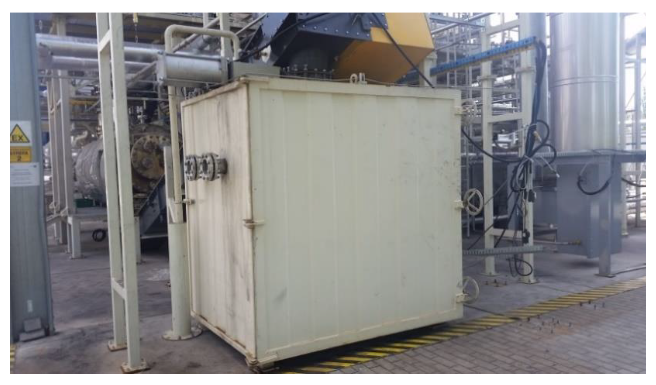
The depolymerization process involves the creation of solid contaminants in the form of carbon. Owing to the extraction system, their content is less than 5%. The P203 and P204 pumps pick up the reaction mass together with the contaminants from the reactor bottom and pump it back into the device through filters F101 and F102. The contaminants included in the mass are separated on plate filters with a vibration-induced dump system [
21]. They are removed from the filter gravitationally in the form of a rolled out deposit through the ZB101 tank-sluice and then captured by the feeder with the PK201 cooling module and stored in the K201 container, both presented in
Figure 5. The deposit is collected manually by the plant staff members.
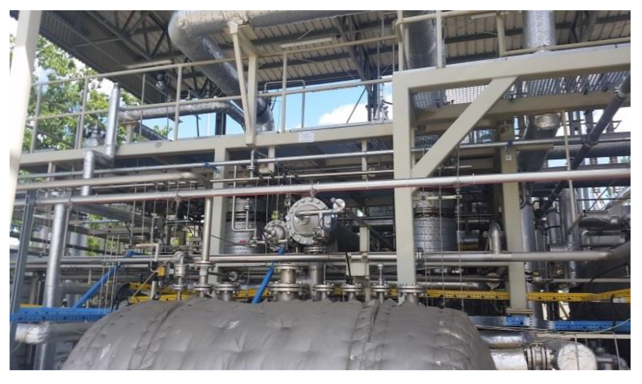
3.15. Liquefaction of Gaseous Products of Cracking
Due to thermal cracking, a stream of vapors is emitted from the reactor with a temperature of 420 °C and a mass flow of 1000 kg/h. Considering the high temperature of the vapors and their inhomogeneity (they are a mixture of particles with a different number of atoms of carbon in a single molecule (from C20 to C5)), single-stage cooling and condensation of products is practically impossible. For this reason, the process takes place in four stages. The first two stages are non-membrane heat exchangers, where the transfer of heat and mass occurs simultaneously in the process of contact between the gaseous and the liquid phase. The exchangers act as scrubbers, washing the stream of hydrocarbon gases flowing through them. The stream of the liquid—condensed hydrocarbon vapors—is carried away gravitationally to intermediate (buffer) tanks. A fragment of this system is shown in
Figure 6. Further on, the cooling stages are membrane and shell-and-tube heat exchangers with a tank-like structure. The gas stream leaving the last liquefaction stage is directed through a separator (demister) and a hydraulic valve (acting as the gas scrubber and absorber at the same time) to a bell buffer tank. From there, it is fed to the purification system and to a set of burners, where it is fired [
20]. The produced heat is used to heat the R101 reactor and to sustain the process taking place in it. In this way, the energy released in the thermal cracking process is used partly to sustain the process itself. The heat in the liquefaction system is given up in a forced-draught cooling tower and in a rack-type refrigeration unit.
3.16. Inertisation System
One condition of the safe process of depolymerization of polyolefins is to maintain an explosion-hazard-free atmosphere in the production system, i.e., an atmosphere containing less than 10% oxygen. In this respect, the most dangerous moments of the process system are the start-up, when the system inside is filled up with atmospheric air, and the shutdown, when ambient air may be sucked into the system. To minimize the hazard of an inside explosion, the system is filled with inert gas (nitrogen) before the start-up. The nitrogen source is a membrane nitrogen generator supplied with compressed air or, alternatively (in an emergency), a container with compressed liquid nitrogen equipped with the evaporation and pressure reduction system.
The system for compressed air and nitrogen production and distribution [
19] is a branched and open structure. The diameters of pipelines are selected to match the output. The system can be extended, and a closed, ring architecture can be achieved.
Compressed air is generated by three compressors in parallel with a capacity of 288 m
3/h each, which gives the total stream of 864 m
3/h of air compressed under a pressure of up to 10 bar [
19]. The compressed air and nitrogen system was made in accordance with Poland’s and EU’s regulations; the CE certification mark was awarded, including conformity assessment; and a nameplate was put on it. The oil–water condensate (emulsion) removed from the devices (compressors, separators, filters, drainers, tanks) may contain from 500 to 5000 mg of oil per liter. It is captured and purified in the separator before being directed to the sewage system. The oil content in the condensate discharged into the sewage system is less than 15 mg/dm
3, which complies with the Polish and European law.
3.17. Supply and Control of the Depolymerization Line and the Process Visualisation
All signals received from the facility are input into a master controller placed in a cabinet in the Control Room, next to the production system. This is also the location of a UPS (Uninterruptible Power Supply) system with the battery power and capacity capable of sustaining the power supply of the system control up to 48 h, which is long enough to bring the process to a complete and safe halt in the case of the system supply voltage failure. The control system has a distributed structure: the master controller co-operates with control islands located in the system devices [
19].
4. Heat Demand of the Process System
The extractor operates continuously with the feeding rate of the pre-sorted raw material and solvent at the level of 1000 and 2000 kg/h, respectively. The anticipated average temperature inside the device is 140 °C. The extraction process heat demand is about 160 kWt. Heat is supplied by side heat exchangers (about 20 kWt) and by pure solvent with excess temperature: 140 kWt (the solvent is heated in the W401/E202 exchanger).
Due to considerable differences in the raw material composition, the demand for heat in the reactor varies. However, it does not exceed 1200 kWt on average. The R101 reactor is equipped with a system of eight heating gas burners (Patent (PL) 229851, 2018) with a power of up to 200 kWt each, which ensures the maximum heat flux reaching 1600 kWt.
The plant includes a four-stage system of liquefaction of gaseous products of cracking. The heat flux to be collected to liquefy the post-cracking stream and needed for further cooling of liquefied hydrocarbon fractions totals about 590 kWt.
The heat carried away from the process, included in the stream of combustion gases leaving the heating system of the R101 reactor and the exhaust gases from power generators, is recovered in ten recuperators mentioned above. This system is a part of what is referred to as the cogeneration system. The exchangers are membrane rectangular prism-tube structures with a total nominal power of 1265 kWt. The liquid heating medium in them is thermal oil. The thermal oil system has two heat sources: the upper heat source—the exchangers as above—and the lower heat source—exchangers where oil gives up heat to other systems. These include heat exchangers heating the extract and the suspension in the R201 extractor and in the filter separator, respectively, and the JAD-type heat exchanger in the thermal substation heating the aqueous solution of glycol, used to heat other devices in the depolymerization line and in the plant (hot tap water). In the thermal substation, the heat can also be directed to heat rooms in the plant (through an extra plate exchanger).
The demand for electric power of the sorting line together with the raw material preparation unit totals about 450 kWe, whereas the depolymerization line consumes about 350 kWe. The plant’s total demand for electric power is 800 kWe.
The cooling medium is the aqueous solution of glycol with a concentration of 30% to 35%, circulating in a closed cycle between the heat exchangers and the E200 membrane forced-draught cooling tower. The cooling tower makes it possible to achieve a difference between the inlet and outlet temperatures of the order of 5 °C at the difference between the air temperatures of the order of 7 °C. The applied cooling tower has five double sections of fans (1) with a total thermal power of 530.1 kWt. In the last cooling stage, the gas, composed mainly of methane, ethane, propane and butane and small amounts of other heavier hydrocarbons, flows through a shell-and-tube cooler cooled with an aqueous solution of glycol with the inlet temperature of −5 °C. The upper heat source is a rack-type refrigeration unit with a power of 2.0 kWt. Due to the gas stream cooling, there is no danger of condensation of hydrocarbon fractions in the pipelines transporting the gas to the burners. Consequently, there is no danger that the burners will be blocked or that they will malfunction.
Considering that the freezing point of some of the products, the heavy fraction in particular, is higher than 50 °C, the plant is equipped with a system heating both the pipelines and operating tanks. All the plant elements, from the R101 reactor to the coolers, are insulated using chloride-free mineral wool or reusable ceramic composite mattresses. The plant heat source is recovered waste heat.
5. Technological Processing and Directing the Fuel Mixture for Sale and to Power Generators
Through intermediate tanks, the obtained hydrocarbon fractions are directed to product composition systems and to underground storage tanks. From there, they can be collected through a legalized flowmeter to supply power generators and road-tank loading stations to sell liquid semi-products to consumers on the market.
The end products of the plastic depolymerization process are stored separately in the M101 and M102 underground two-shell tanks with the capacity of 80 m3 each:
- -
in the M101 two-chamber tank, chamber K1 with the capacity of 16 m3 holds petrol products; the 64 m3 chamber K2 is used to store oil products;
- -
in the M102 two-chamber tank, chamber K3 with the capacity of 40 m3 holds paraffin products; the other 40 m3 chamber K4, legalized by the Central Office of Measures (GUM), is used to store excise energy products intended for release to power generators or to external entities.
Fiscally, in the tax warehouse, K1, K2 and K3 are process chambers, whereas K4 is a storage chamber—it holds products before they are released from the warehouse. Each chamber in the tanks is equipped with an analytical apparatus measuring the level, temperature and the acid–base indicator (pH). Each chamber also has a stirrer generating the liquid circulation and stabilizing its parameters. The chambers are also equipped with coils supplied with a water-glycol heating solution to maintain appropriately high temperatures in each chamber.
Individual fractions can be collected from the chambers of underground tanks by pumps operating in the pump unit. The fractions are then pumped through a static mixer. They mix in the flow, creating stable solutions or mixtures. The products made in this way can be filtered and subjected to further treatment at the molecular level in a treatment plant (SUP/UOK) to achieve adequate quality. The mixing of fractions according to a specific procedure results in fuel intended for power generators—Energy product: GreenOil (light hydrocarbon distillate), described by the data sheet version: 1.0/EN of 10 September 2018, prepared in accordance with Regulation EC 1907/2006 of the European Parliament and Council and Regulation EC 453/2010 specifying the product properties and procedures related thereto according to the best available knowledge [
19]. Selected properties for the fraction are presented in
Table 3.
All energy products made in the plant, including their preparation for shipment and sale, marking and further use guidelines, are handled in accordance with Poland’s and EU’s regulations. Before it is supplied to power generators or pumped into road tankers, the GreenOil energy product flows through a measurement and settlement system, based on the Coriolis mass flowmeter, owing to the implemented API features and legalized by a Notified Body, acc. to MID and OIML Directives. Due to the specificity of its production and processes, the plant operates a tax warehouse, and the hydrocarbon components made in it are subject to excise duty in accordance with relevant regulations. A partial economic balance of the plant’s operation for the selected period, specified on incomes (recycling fees, sales of sorted waste and products) as well as costs (administrative, salaries, utilities), is presented in
Table 4.
6. Conclusions
Based on a (partly comparative) assessment of the condition of the plant, including the process line, it can preliminarily be concluded that the plant (depolymerization unit under the umbrella roof pictured below) was commissioned properly and the processing system is sufficiently complete in terms of its main task, i.e., carrying out processes of recycling of package waste. The system also provides the basis for the plant’s safe operation. According to the authors, the plant is now the most modern enterprise operating in Poland that provides commercial recycling of waste plastics in the process of depolymerization. It is also one of the most advanced plants offering such services in Europe.
It should be noted that the process line is characterized by novel, innovative solutions, such as the patented method of cleaning the reactor’s internal elements and purification of the reaction mass or carbonization of post-process residues. The advantage of the presented technology is the substantial simplification of the process and, thereby, a considerable reduction in investment costs. Among others, the processes of distillation and rectification (low- and negative-pressure) were abandoned. The experience was used of the Polish refineries, where column plates were blocked when the column was supplied with KTS–F (plastics component fractions). The incident necessitated costly cleaning and repair works on the column and some parts of the system. The process outcome are excise energy products which are hydrocarbon components. They can be used successfully as additives to heating oils and other refinery products. They are also suitable for many common-use products such as adhesives, solvents, etc.
Such a system has never been put into operation on an industrial scale before, but the process was known owing to the testing performed previously in a pilot plant at a small industrial scale. The experience made it possible for the user—the plant owner—to learn the specificity of the process, identify the hazards that the process creates, pre-select the most advantageous initial parameters and define assumptions for the design of devices and other elements operating within the system.


