1. Introduction
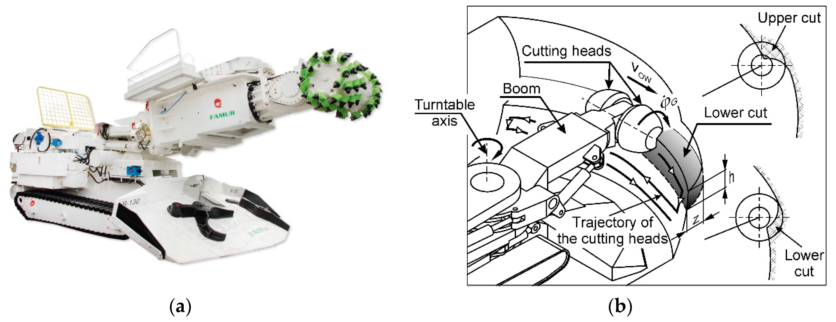
Boom-type roadheaders (
Figure 1a) are widely used in civil engineering for drilling roadways in underground mines and partly for drilling tunnels. Rock cutting is carried out using cutting heads armed with conical picks, located at the end of a movable boom. This helps in moving the cutting heads along the heading face of the tunnel, with the cutting technology adapted to the geological structure of the rock mass in which a given tunnel is drilled. In the most commonly used rock cutting technology, the cutting heads are moved parallel to the floor from one sidewall of the excavation to the other (
Figure 1b). After moving the cutting heads up or down, another cut is made towards the opposite sidewall of the drilled roadway or tunnel. Although there has been intensive development in the mining technologies and those used in machines, roadheaders are still manually controlled. The boom deflecting drives are controlled by the operator with a joystick, and as a result, the cutting heads are moved on the heading face of the drilled tunnel in a certain manner at a given movement speed. The effectiveness of the cutting process is determined by the following four parameters: web of cut
z, cut height
h, the movement speed of the cutting heads in working motion
vOW, and angular speed of the cutting heads
. If a roadheader is manually controlled, the values of the first three parameters are set by the operator. The fourth parameter is constant because it is determined by the angular speed of the electric motor and the gear ratio of the gearbox in the cutting heads drive. Manual control does not allow optimizing the values of the cutting process parameters, which often results in low mining efficiency, especially in the case of hard rocks, as well as high energy consumption and significant dynamic overloading of the roadheader.
For many years, researches have been carried out at various R&D centers to develop advisory systems to aid the operator in selecting optimal values of working parameters and automatic control systems for roadheaders. These have led to, among others, the development and implementation of remote control systems and diagnostics for roadheader working parameters [
3,
4], as well as systems that can support the operator in guiding the cutting heads within a given excavation contour and assist him in selecting the operating parameters [
5,
6]. An essential step towards the robotization of roadheaders is the research aimed at developing solutions enabling programmatic control of boom movement, which allows choosing the trajectory of the cutting heads or implementing their movement according to a given (learned) trajectory after a reference cut is performed [
7,
8,
9,
10]. In addition, some solutions enable automatic profiling of sidewalls and roof to adapt their shape to that of the used roof support [
6,
7,
9,
10]. The research also attempted to optimize the boom swinging speed and the parameters of the cut layers [
11,
12,
13].
An important area of research and implementation in the development of roadheaders was the design of positioning systems for these machines to the axis of the drilled excavation [
6,
14,
15,
16,
17,
18] and works aimed at using vision systems and scanning techniques for recognizing the geological structure of the rock mass within the heading face of the drilled tunnel [
19,
20,
21,
22,
23]. These works also provide the ground for the development of a fully autonomous roadheader.
Automation and robotization of boom-type roadheaders have been very well explored so far, but solutions are yet to be found for automatic control systems of roadheaders to enable effective and efficient drilling of roads and tunnels, especially in severe geological and mining conditions, and to fully utilize the technical potential of these machines. However, simulation and experimental research, which has been conducted for 30 years at the Department of Mining Mechanization and Robotisation of the Silesian University of Technology (Poland), indicates that by skilfully controlling the cutting process parameters of the heading face, one can meet the basic operational requirements. This includes ensuring a high drilling speed (efficiency) with the lowest possible energy demand as well as ensuring the expected durability and reliability of roadheaders. They can be achieved by optimizing the cutting process parameters with respect to the following essential criteria (objective functions):
the criterion of optimal use of the roadheader’s cutting system power,
the criterion of reducing dynamic loads and vibrations in the structural nodes of the roadheader, and
the criterion of minimum energy consumption.
This optimization boils down to searching for a combination of cutting process parameter values that are appropriate to the conditions of this process. The above-mentioned optimization criteria constitute the starting point for the formulation of the control criteria based on which the automatic control procedure should be carried out. These criteria are presented later in this paper.
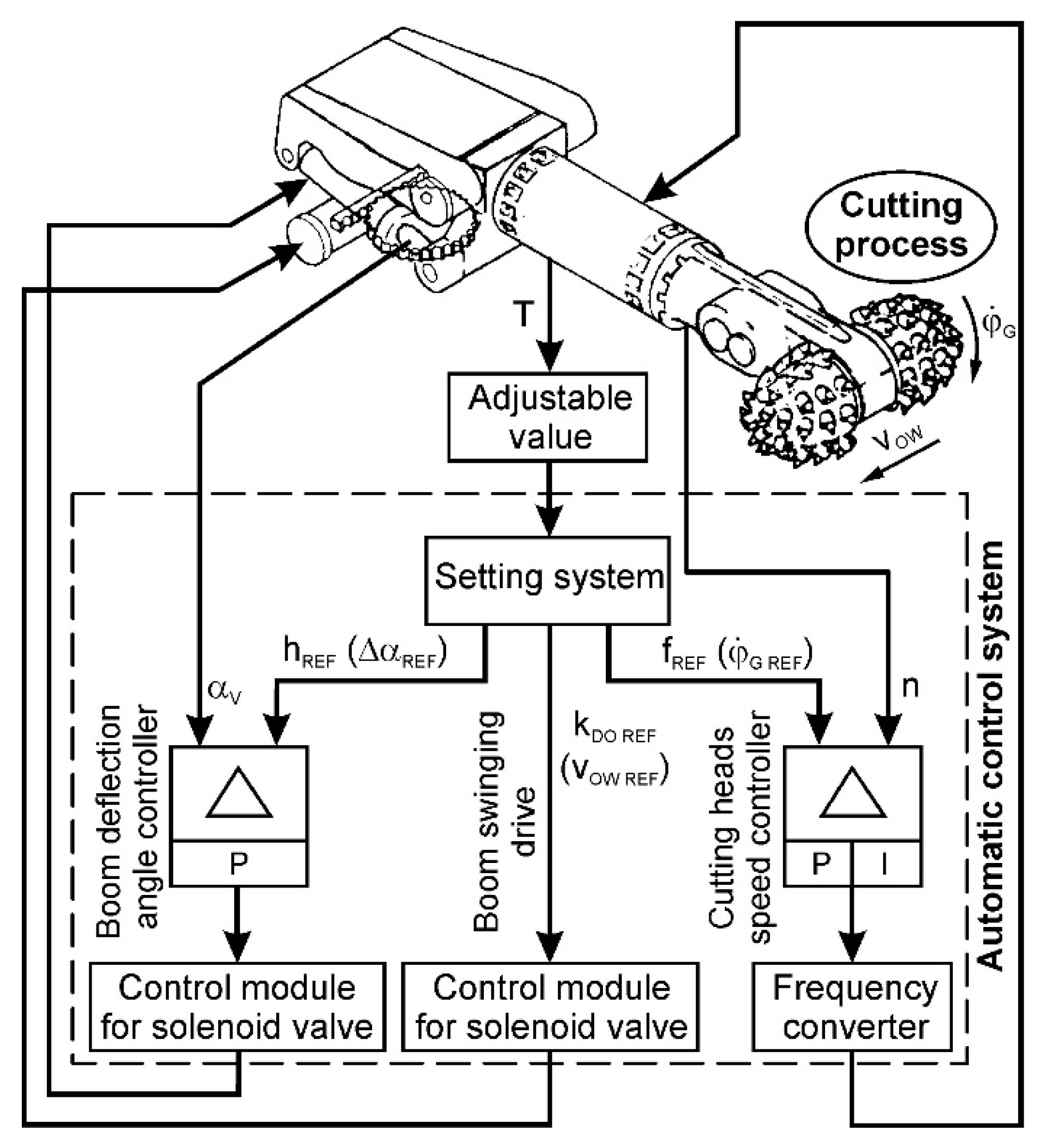
The cutting process is not stationary. One reason for this is that the rock mass in which underground roadways and tunnels are drilled often has a layered structure. It is characterized by the separation of soft rock layers by hard rock layers lying in different ways in the cross-section of the drilled excavation. This means that the selection (correction) of the mining process parameters must be done online, as the cutting heads move along the heading face, which is possible only with the automatic control of the cutting heads movement. In the developed solution of such a system, the values of three of the four cutting process parameters are regulated: the angular speed of the cutting heads
, their movement speed in working motion
vOW and the cut height
h (
Figure 2). It is a new approach to the automatic control of the cutting process, because so far only the automatic control of the movement speed of the cutting heads or their angular velocity has been taken into account. Of these, the angular speed of cutting heads, which until now has been kept constant or changed abruptly due to switching gears of the motor or the gearbox, is of great importance [
24,
25]. For practical reasons, it has been assumed that the infinitely variable angular speed adjustment of the cutting heads will be implemented using a frequency converter that supplies the electric motor in the roadheader’s cutting system. The web of cut and mechanical parameters of excavated rocks are treated as random variables. The parameters of the cutting process are optimized in the setting system. This block, based on the response of the controlled object—the course of the adjustable value (dynamic load of the cutting heads drive), works out the set values of the cutting process parameters in subsequent rotation periods of the cutting heads. As the angular speed of the cutting heads is variable (programmable), these periods are variable.
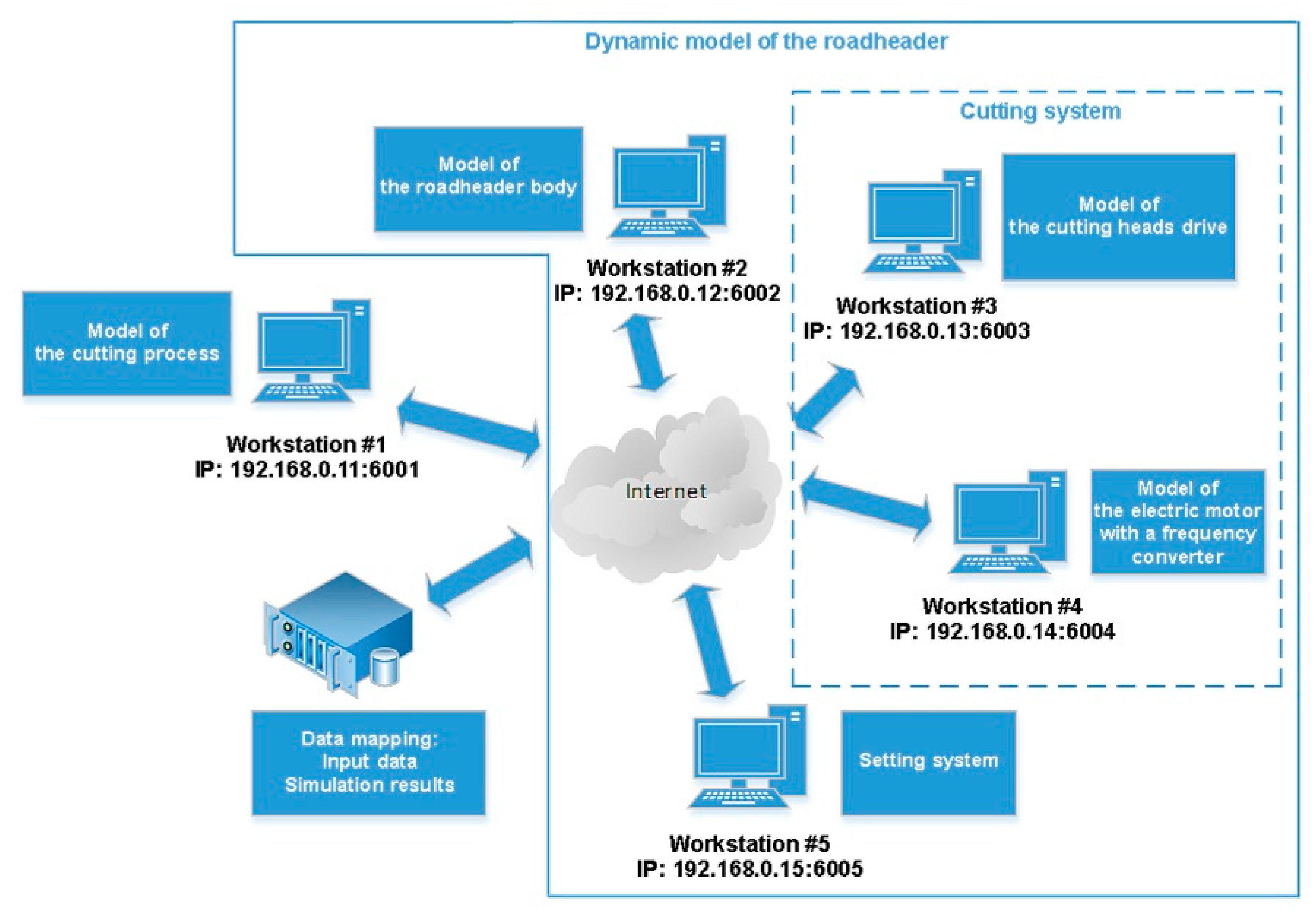
The paper presents selected results of numerical tests on roadheader dynamics, which simulated the automatic control system operation of the heading face cutting process of the drilled roadway or tunnel. These tests were intended to analyze the behavior of the tested object during simulated rock mining in automatic mode. The studies used the original mathematical models:
As the above-mentioned mathematical models are complicated and require the use of various programming environments for their implementation in computer software (Matlab, Simulink, RAD Studio), a distributed simulation system has been developed for roadheader dynamics during mining
SIMCUT for integrating them (
Figure 3). This system combines the software that solves the mathematical models of individual roadheader components and a model of the rock cutting process, as well as simulates the operation of the control system. As part of this simulation system, each computational model can run on a separate workstation. Data exchange between the individual computational models is achieved via the Internet. This system is equipped with a dedicated file server that stores all the essential files (configuration files and executables) as well as the data and simulation results [
31].
Numerical tests were carried out for the R-130 roadheader (
Figure 1a) (made by Famur SA) installed on the experimental stand, followed by the testing of the developed automatic control system on a semi-industrial scale. This roadheader, with motor power in the cutting system of 132 kW (
Table 1), is the most popular type used for drilling roadways in the Polish underground mines. For the research, it was equipped with two transverse cutting heads, having a maximum diameter (
Dmax) of 840 mm and a length (
L) of 495 mm, each armed with 54 conical picks.
2. Determining the Possibilities of Reducing Dynamic Loads and Energy Consumption during Mining through Proper Selection of the Cutting Process Parameters
The analyses of the control characteristics of the boom-type roadheader carried out in numerical tests indicated that the assumed objective of automatic control (resulting from the adopted criteria for optimizing the cutting process) can be achieved by appropriate control of the cutting process parameters, in particular the angular speed and movement speed of cutting heads. The adjustment characteristics of the roadheader (dependence of the torque, power, cutting energy consumption, dynamic load of the boom deflection mechanisms, and boom vibration acceleration on the speed of movement of the cutting heads and their angular velocity), determined for different combinations of the web of cut and the cut height and different workability of the rocks form a set of curves of a complex shape. They have local maxima as well as local minima. It is important to choose such a combination of the cutting process parameters to ensure that the roadheader can work in the area of local minima of these characteristics, or in the range of favorable values. The last condition applies in particular to the power consumed by cutting because the drive system of the cutting heads should neither be overloaded excessively nor work with a high underload (failure to use the technical potential of the machine). Because the cutting process is not stationary, it is necessary to constantly adjust the values of the parameters of the cutting process to achieve the above-mentioned goal [
24,
25].
These speeds are, respectively, determined by
the frequency of the motor supply voltage f in the drive of the cutting heads, and
the opening coefficient kDO of the electrohydraulic valve in the supply system of the boom swinging actuator.
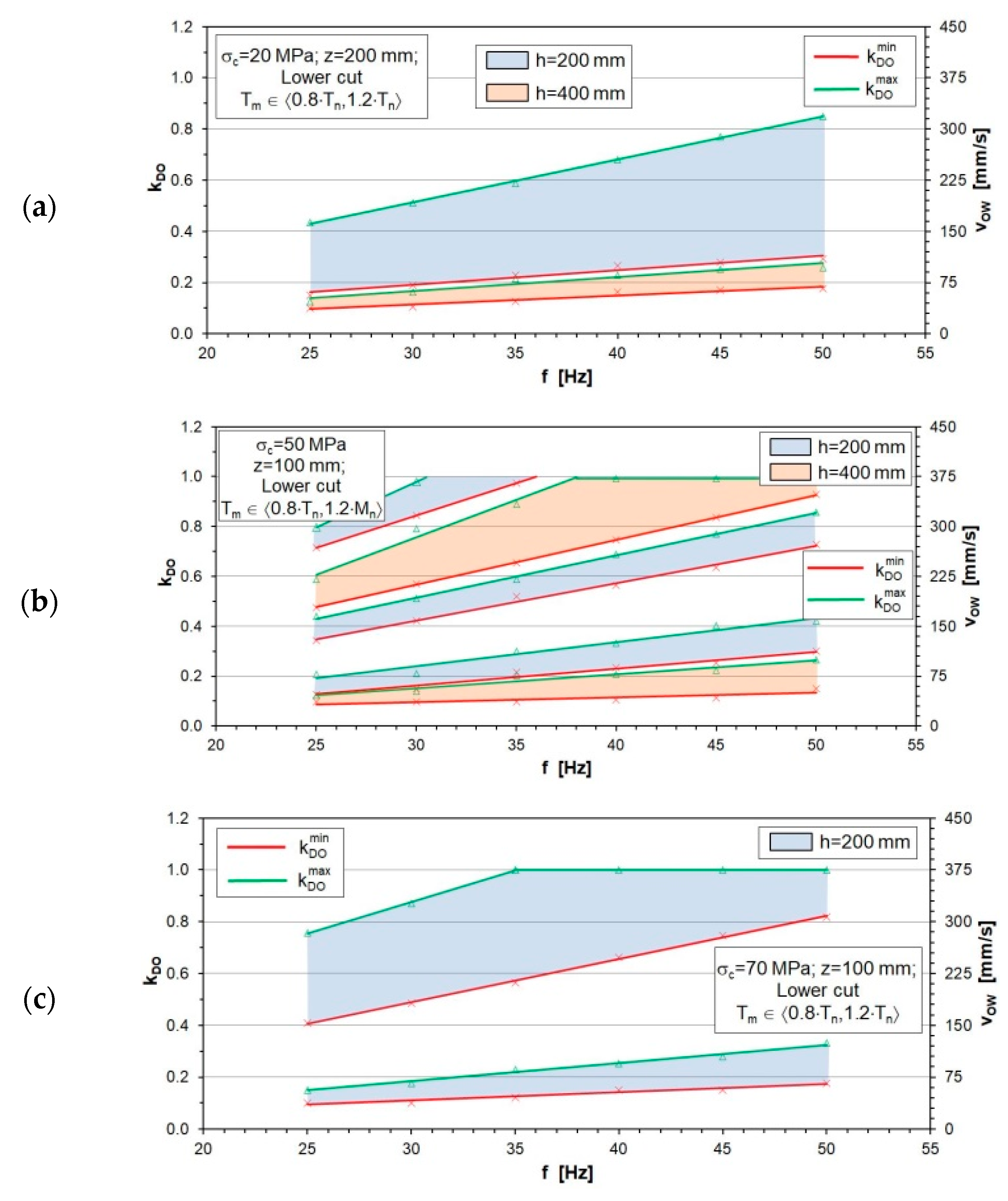
Therefore, there are two-element sets in the form {
f,
kDO}, for which the control criterion is adopted (
Figure 4). Points reflecting the above-mentioned associations create areas (bands) determining the ranges of the variability of the control quantities, for which the adjustable value (torque on the motor shaft in the cutting heads drive) will reach the assumed acceptable level. These areas are limited by the lines
(red line) and
(green line), exceeding of which is tantamount to the inability to achieve the assumed control criterion. Additionally, these areas are limited by horizontal lines corresponding to the minimum and maximum values of the opening coefficient of the hydraulic valve
kDO as well as vertical lines corresponding to the minimum and maximum frequency of the motor supply voltage
f.
For the optimal use of the roadheader’s cutting system power, it is required to select appropriate values of the cutting process parameters for which the average dynamic load values of the cutting heads drive Tm will be close to the nominal value of the motor torque Tn. As cutting is not treated as a stationary process, the average torque values on the motor shaft may be within the tolerance of a specific nominal value. Considering the mechanical characteristics of the electric motor in the cutting heads drive of the R-130 roadheader, the average torque values on the motor shaft were assumed to be in the range from 0.8⋅Tn to 1.2⋅Tn. When Tm > 1.2⋅Tn, the drive of cutting heads should be considered overloaded. On the other hand, when Tm < 0.8⋅Tn, this drive is underloaded. A very low average load from cutting compared to the roadheader’s technical capabilities is regarded as undesirable, as well as its overloading. As the conducted power balance indicates, a very low load on the cutting heads drive from mining leads to poor efficiency, which is due to high constant losses of the converter drive.
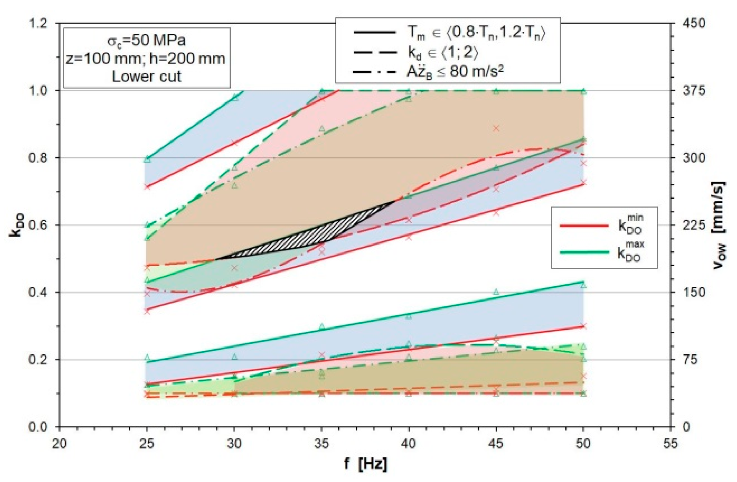
The location and shape of the areas created by the sets {
f,
kDO} that meet the above-mentioned control criterion depend on the cross-section of the cut (resulting from the web of cut
z and cut height
h) and the uniaxial compressive strength of the rock being cut (
σc). It is noteworthy that in some cases, a given angular speed of the cutting heads (supply voltage frequency of the motor in the cutting system
f) may correspond to several ranges of their movement speed (opening coefficient values of the hydraulic valve
kDO). One such case is when the mining rock has a uniaxial compressive strength (
σc) of 50 MPa with a web of cut (
z) of 100 mm and a cut height (
h) of 200 mm. For a supply voltage frequency
f of 25–35 Hz, there are three such ranges (
Figure 4b, areas in blue). However, if
f > 35 Hz, each value of frequency
f corresponds to the value of
kDO coefficient from two ranges. Therefore, the optimal use of the roadheader’s cutting system power can be achieved only for specific associations of the motor supply voltage frequency and the opening coefficient of the electrohydraulic valve in the supply system of the boom swinging actuator.
For a twofold higher cut height (h = 400 mm), the values of the supply voltage frequency f from the entire considered range correspond to that of the kDO coefficient from two ranges (areas in orange).
As can be seen, the colored fields reflecting the associations of the cutting head speed values in rotational and translational motion, for which the said control criterion can be met, for a given cross-section of the cut, are detachable and quite far apart. On the other hand, the areas in white are formed by sets of values {f, kDO}, for which the average motor load in the cutting system does not meet the considered control criterion (does not fit in the assumed bandwidth).
Considering the dynamic load nature of the roadheader during its working process, it would not be sufficient if the control is solely based on the assessment of the average load value. Working out the values of the control quantities by the automatic control system should also ensure reducing the dynamic loads and vibrations that adversely affect the work of the mining machine and the surrounding environment. However, simultaneous compliance with several control criteria may complicate the task of selecting the cutting process parameters. To achieve the assumed control effects (criteria for optimizing the cutting process parameters), the following control criteria have been formulated based on previously described computer tests [
24,
25]:
the criterion of the optimal use of cutting heads drive power: (discussed above),
the criterion of permissible dynamic overload: ,
the criterion of vibration reduction: , and
the criterion of minimizing energy consumption during mining: E → min.
The dynamic overload of the cutting heads drive is determined by the dynamic overload coefficient
kd, which is defined as the ratio of the peak value of dynamic load in the considered time interval (rotation period of the cutting heads) to the nominal value of the motor torque:
. In turn, the intensity of roadheader vibration is determined by the amplitude of the boom transverse vibration acceleration (in a plane perpendicular to the floor)
. On the other hand, mining energy consumption
E is defined as the ratio of mechanical power consumed for carrying out the cutting process to the efficiency of this process [
32]:
where
E is the energy consumption of mining (kWh/m3),
P is the average power used for cutting (kW),
Q is the average cutting efficiency (m3/h),
iG is the gear ratio of the cutting heads drive,
Tm is the average torque value on the motor shaft (calculated for the rotation period of the cutting heads) (Nm),
S is the cross-sectional area of the cut (m2),
vOW is the movement speed of cutting heads (m/s),
is the angular speed of cutting heads (rad/s), and
η is the efficiency of the cutting heads drive.
For a given web of cut value
z and cut height
h, associations of the angular speed values and movement speed values of the cutting heads can be determined, for which the first three control criteria are separately met. In such a case, the points mapping the sets {
f,
kDO} form the areas corresponding to a particular control criterion (
Figure 5). For example, when making the lower cut (
Figure 1b) in rock with a uniaxial compressive strength (
σc) of 50 MPa, with a web of cut (
z) of 100 mm and a cut height (
h) of 200 mm, the areas reflecting the associations of values of the considered cutting process parameters have a common part. However, this corresponds to a fairly narrow range of frequency
f and
kDO coefficient (
Figure 5, the area bounded by a black line), and has approximately the shape of a triangle, the dimensions of which determine the variability ranges of parameters characterizing the movement speed of cutting heads:
the frequency of motor supply voltage f in the cutting system—from 29 to 40 Hz, and
the opening coefficient of the hydraulic valve kDO in the actuator supply system in the boom swinging mechanism—from 0.50 to 0.67.
It follows that for a given combination of the web of cut and cut height values, the above-mentioned control criteria can be simultaneously fulfilled only for a fairly limited set of values of the angular speed and movement speed of cutting heads.
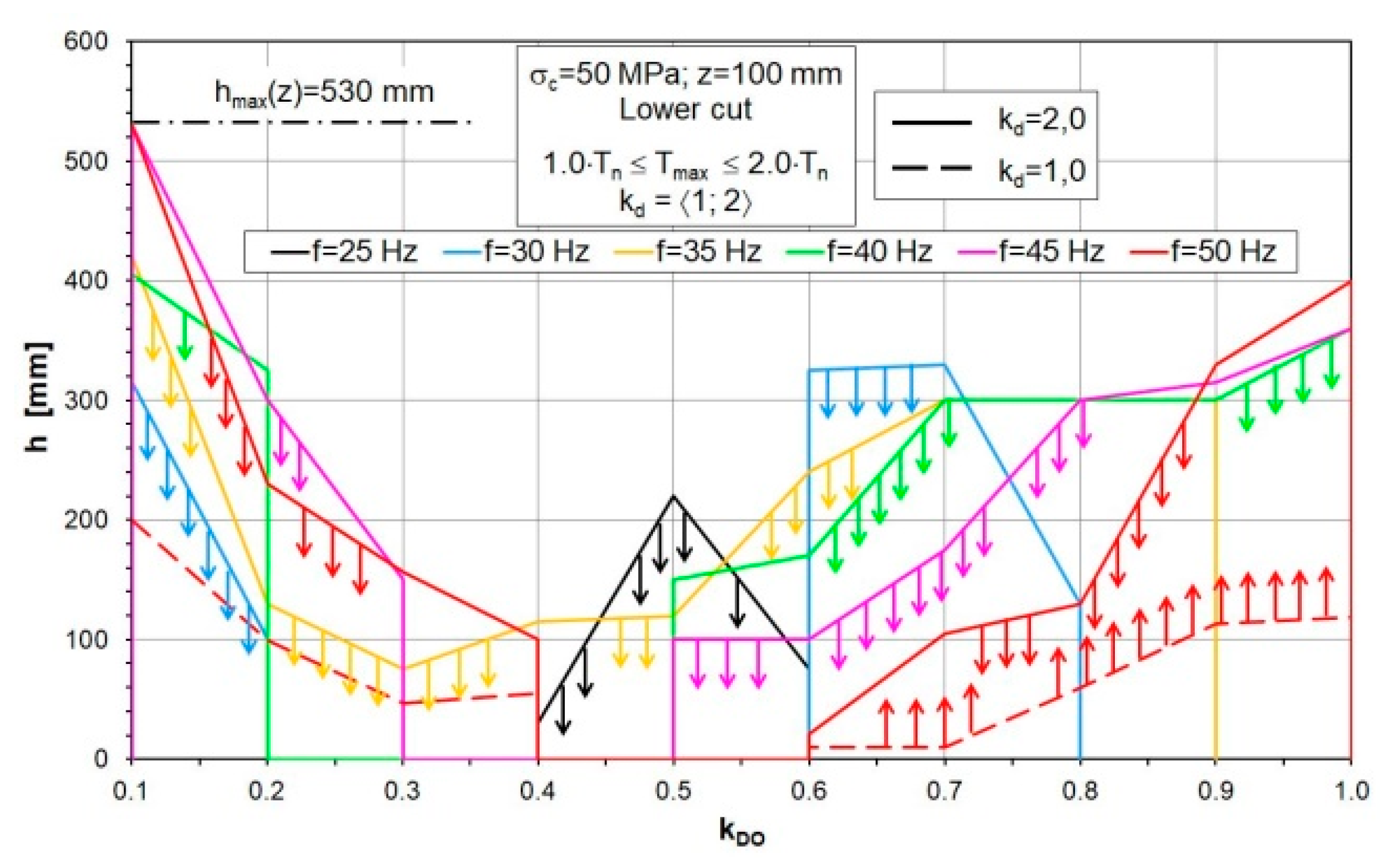
As shown in these example cases, controlling the angular speed and movement speed of the cutting heads may not be sufficient when multiple control criteria are to be met. One way to solve this problem is to control the cut height
h additionally as illustrated in
Figure 6. The relationship between the cut height
h, the angular speed of the cutting heads (described by the frequency of the supply voltage
f), and their movement speed (described by the opening coefficient of the hydraulic valve
kDO) that allows the criterion of the permissible dynamic overload to be met is shown in the figure. This example concerns the mining of rock with a uniaxial compressive strength
σc of 50 MPa with a web of cut
z of 100 mm. As can be seen, for each angular speed of the cutting heads, their movement speed and the ranges of the cut height can be determined, so that the above control criterion is met. Here, there are intervals for the movement speed of the cutting heads (
kDO coefficient), in which it is not possible to meet this criterion at a given angular speed of the cutting heads (frequency
f). This situation occurs, for example, when
f = 50 Hz and the value of
kDO coefficient ranges from 0.4 to 0.6 (red line), or when
f = 30 Hz and
kDO = 0.2–0.6 and >0.8 (blue line).
Associations of {
f,
kDO,
h} values, for which the criterion of permissible dynamic overload is met, create areas bounded from the top by a solid line, corresponding to
kd = 2. Due to the avoidance of strong motor underload, an additional lower limit was introduced for the peak values of the dynamic motor load in the cutting system (
kd = 1). It was revealed only for the highest studied angular velocity of the cutting heads (
f = 50 Hz), marked with a dashed line. Ranges (areas) of the cut height
h corresponding to individual cutting heads speed (
f and
kDO), for which the considered control criterion is met, are indicated by arrows in
Figure 6.
While developing an automatic control system on an industrial scale, the controlled (adjustable) value (output from the process) is the torque on the motor shaft of the cutting heads drive (measured directly or indirectly). Therefore, the following two control criteria are of key importance: the criterion of the optimal use of the cutting heads drive power and the criterion of the permissible dynamic overload. Based on these, the control values (working process parameters) are developed by the setting system. As indicated by the conducted simulation tests, in addition to reducing the dynamic loads in the cutting system, this will ensure that a reduction is achieved in the dynamic loads of other roadheader body components, the boom deflection mechanisms, and the vibration intensity of the roadheader (third criterion). Minimization of energy consumption (fourth criterion) can be achieved on the one hand by reducing the load on the cutting heads drive and on the other by carrying out the cutting process at the highest possible movement speed of the cutting heads. The simulation tests indicated that for the tested roadheader, it is possible to achieve this effect at the cutting heads movement speed (vOW) of >200 mm/s (kDO > 0.5).
3. Simulation of Roadheader Dynamics with the Automatic Control System of the Cutting Process
The results of the simulation tests were the basis for designing the structure of the automatic control system needed for its implementation in a real machine. While conducting simulation tests, parameterization, and tuning of its elements (setting system and the applied regulators) were also performed. Execution and testing of the automatic control system on a real object were preceded by computer tests.
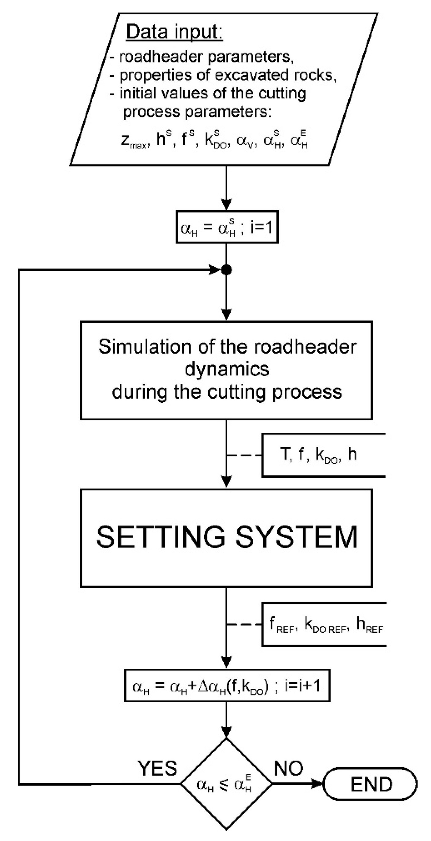
The automatic control of the cutting process parameters is implemented by an algorithm saved in the setting system. The simulation of roadheader dynamics with the automatic control system begins with entering the following data (
Figure 7):
the characteristics of the roadheader (geometrical, mass, elastic, damping, kinematic, and power parameters, and in particular the cutting system parameters and the cutting heads stereometry);
the mechanical properties of the excavated rock (mechanical parameters and those describing the geometry of individual rock layers lying in the heading face of the drilled excavation); and
the initial values of the cutting process parameters, from which the simulation process begins, such as
zmax—the maximum web of cut in the longitudinal axis of the excavation,
hS—the initial cut height,
—the initial frequency of the motor supply voltage in the cutting system determining the initial angular speed of the cutting heads,
—the initial opening coefficient of the electrohydraulic valve in the supply system of the boom swinging actuator in a plane parallel to the floor,
αV—the boom deflection angle perpendicular to the floor,
—the initial boom swinging angle in a plane parallel to the floor from which mining starts, and
—the final boom swinging angle in a plane parallel to the floor at which the excavation ends.
Starting from the initial boom swinging angle in a plane parallel to the floor (), for the first rotation of the cutting heads (i = 1), the simulation of the roadheader dynamics is carried out, during which the dynamic load of the roadheader caused by cutting the rock with the cutting heads is determined for subsequent turns of the cutting heads. As the differential equations of motion are solved, time characteristics are determined as waveforms, among others:
of the dynamic moment on the motor shaft in the cutting system T(t);
of the dynamic load of actuators in the boom swinging and the deflecting mechanisms FSO(t) and FSP(t);
of the vibration acceleration components in significant roadheader construction nodes, including boom transverse vibration acceleration ;
of the boom swinging angle αH(t) and the boom deflection angle in a plane perpendicular to the floor αV(t);
of the angular speed of the cutting heads ; and
of the boom swinging speed (movement speed of the cutting heads in working motion) vOW(t).
Based on these, new (corrected) values of the cutting process parameters are determined in the “Setting system” module for the next rotation of the cutting heads (i = i + 1): fREF, kDO REF, hREF. Then, a new boom position is determined in a plane parallel to the floor (boom swinging angle αH increased by the boom angular displacement during the analyzed rotation of the cutting heads ΔαH). After confirming that in its new position the boom swinging angle does not exceed the final value (), the dynamics simulation procedure is repeated with new values of the cutting process parameters. In each subsequent computer simulation cycle, the course of excitation of vibrations from mining is first determined (simulation of the process of mining the heading face of the excavation with the cutting heads). This simulation is carried out for the current values of the cutting process parameters, while also considering the mechanical properties of the rock at the place where the cutting heads are now located. It means that if simulations are carried out for a rock formation with a layered structure, the cutting head’s passage through the contact zones of rock layers of different workability is taken into account.
The values of the cutting process parameters are corrected, concerning the values at which this process was performed in the previous rotation of the cutting heads, by
correcting the boom deflection angle in a plane perpendicular to the floor by the angle ΔαV REF which was determined based on the cut height hREF;
changing the rotor speed of the motor, and thus the cutting heads angular speed , which was determined based on the frequency of the motor supply voltage fREF; and
changing the boom swinging speed vOW REF which was determined based on the opening coefficient of the electrohydraulic valve kDO REF.
While analyzing the dynamic load of the cutting heads drive, the following are estimated:
the average torque on the motor shaft Tm (should be in the range of 0.8⋅Tn to 1.2⋅Tn);
the number of exceedances of the maximum value, determined by the dynamic overload coefficient kd, by the instantaneous torque values on the motor shaft NE (assumed: NE ≤ 500); and
the value of the energy consumption coefficient
WE from the formula derived from (1) [
26]:
where
WE is the energy consumption coefficient (Nm⋅Hz/mm),
f is the frequency of motor supply voltage in the cutting system (Hz),
h is the cut height (mm),
kDO is the opening coefficient of the electrohydraulic valve (–), and
Tm is the average torque on the motor shaft (Nm).
Furthermore, the average and peak values of the dynamic load of the actuators in the boom swinging (FSO) and boom deflecting mechanisms (FSP) are verified with the maximum value resulting from the maximum pressure in the hydraulic system. For boom deflecting actuators, their load resulting from the confirmation of roadheader’s stability is additionally checked. The amplitude and the root mean square (RMS) value of the boom transverse vibration acceleration (, ) are also determined.
The dependence of the cutting system’s dynamic load on the boom swinging speed (movement speed of the cutting heads) are characterized by the occurrence of certain intervals during which the average, maximum, and amplitude values of the dynamic load show either an increasing or a decreasing trend. The location of these intervals depends on the angular speed of the cutting heads [
24]. According to the shape of the control characteristics, the control procedure done by the setting system has three ranges of boom swinging speed in a plane parallel to the floor, depending on the opening coefficient value of the electrohydraulic valve
kDO. Although the initial range of this valve is from 0 to 1 (from 0 to 100%), for practical reasons, the maximum boom swinging speed has been limited by adopting the maximum opening coefficient value (
kDO max = 0.7). For the considered roadheader, three intervals of the boom swinging speed in a plane parallel to the floor were separated, based on the opening coefficient values of the electrohydraulic valve in the supply system of the boom swinging actuator:
the range of the low boom swinging speed (vOW = 40 to ~100 mm/s)—for ,
the range of the medium boom swinging speed (vOW = 100–175 mm/s)—for , and
the range of the high boom swinging speed (vOW = 175–270 mm/s)—for .
In the ranges of low and medium boom swinging speed in a plane parallel to the floor, four cases of a cutting system’s dynamic load are considered (
Table 2,
Case 1 to
Case 4).
Case 5 is additionally considered in the range of high boom swinging speed. It checks whether the value of the mining energy consumption coefficient
WE calculated from formula (2) for a given rotation of the cutting heads is lower than the minimum value obtained so far. If found so, it is taken as the minimum value
WEmin. Separate procedures were developed for determining the new (corrected) values of the cutting process parameters for each distinguished case of the cutting head drive load.
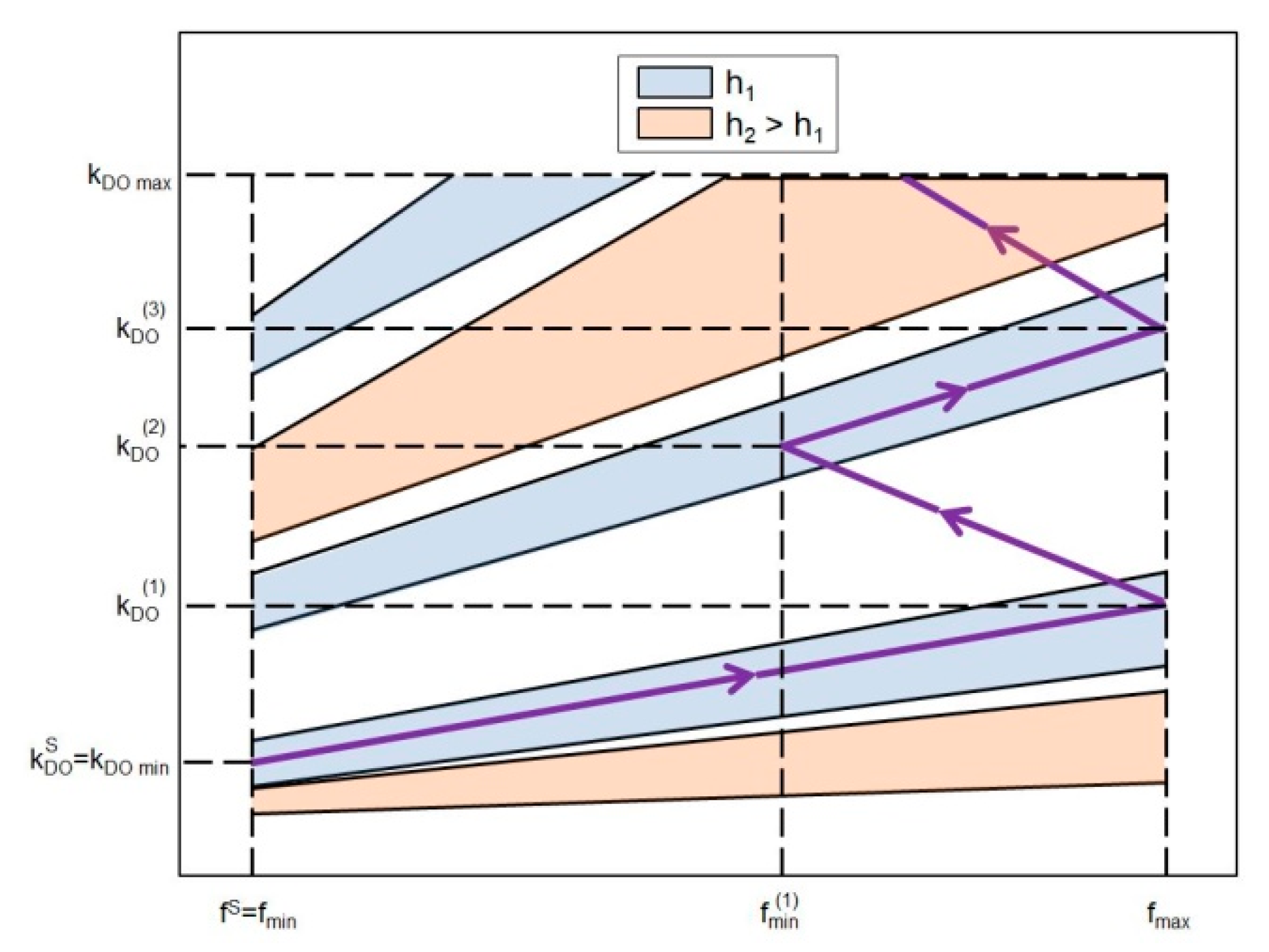
Depending on the dynamic load of the cutting system (one of the five load cases), the setting system determines the new (corrected) values of the cutting process parameters for the next rotation of the cutting heads: the angular speed of the cutting heads by specifying the reference frequency of the motor supply voltage—
fREF, the boom swinging speed by specifying the reference opening coefficient value of the electrohydraulic valve
kDO REF and the reference cut height
hREF (
Figure 2). The idea of the controlling process parameters is shown in
Figure 8. Starting from the initial values—the cut height (
hREF =
h1), the minimum value of the motor supply voltage frequency (
fREF =
fmin) and the minimum opening coefficient value of the electrohydraulic valve (
kDO REF =
kDO min), the speed of cutting heads begins to gradually increase (
fREF↓,
kDO REF↑). After the maximum angular speed of the cutting heads is reached (
fREF =
fmax), the degree of opening of the electrohydraulic valve corresponds to the value of the coefficient
kDO REF =
. From this point, the frequency of the motor supply voltage in the cutting heads drive is periodically reduced (
fREF↓) and increased (
fREF↑) in the range
. This change is accompanied by a systematic increase of the opening coefficient of the electrohydraulic valve, reaching subsequent values:
, …, up to
kDO max. During this time, a possible correction of cut height (e.g.
hREF =
h2) is made to achieve the intended control.
4. Computer Tests of the Behavior of a Roadheader Equipped with an Automatic Control System during Mining
For the first rotation of the cutting heads, the following initial input data were adopted while testing the dynamics simulation of the roadheader equipped with an automatic control system:
= 35 Hz;
= 0.2. An example for the use of the developed control procedure is shown based on a situation where a lower cut is made with an initial height
hS = 150 mm in rock with a uniaxial compressive strength
σc = 50 MPa, with a maximum web of cut
zmax = 100 mm (
Figure 9,
Figure 10,
Figure 11,
Figure 12,
Figure 13 and
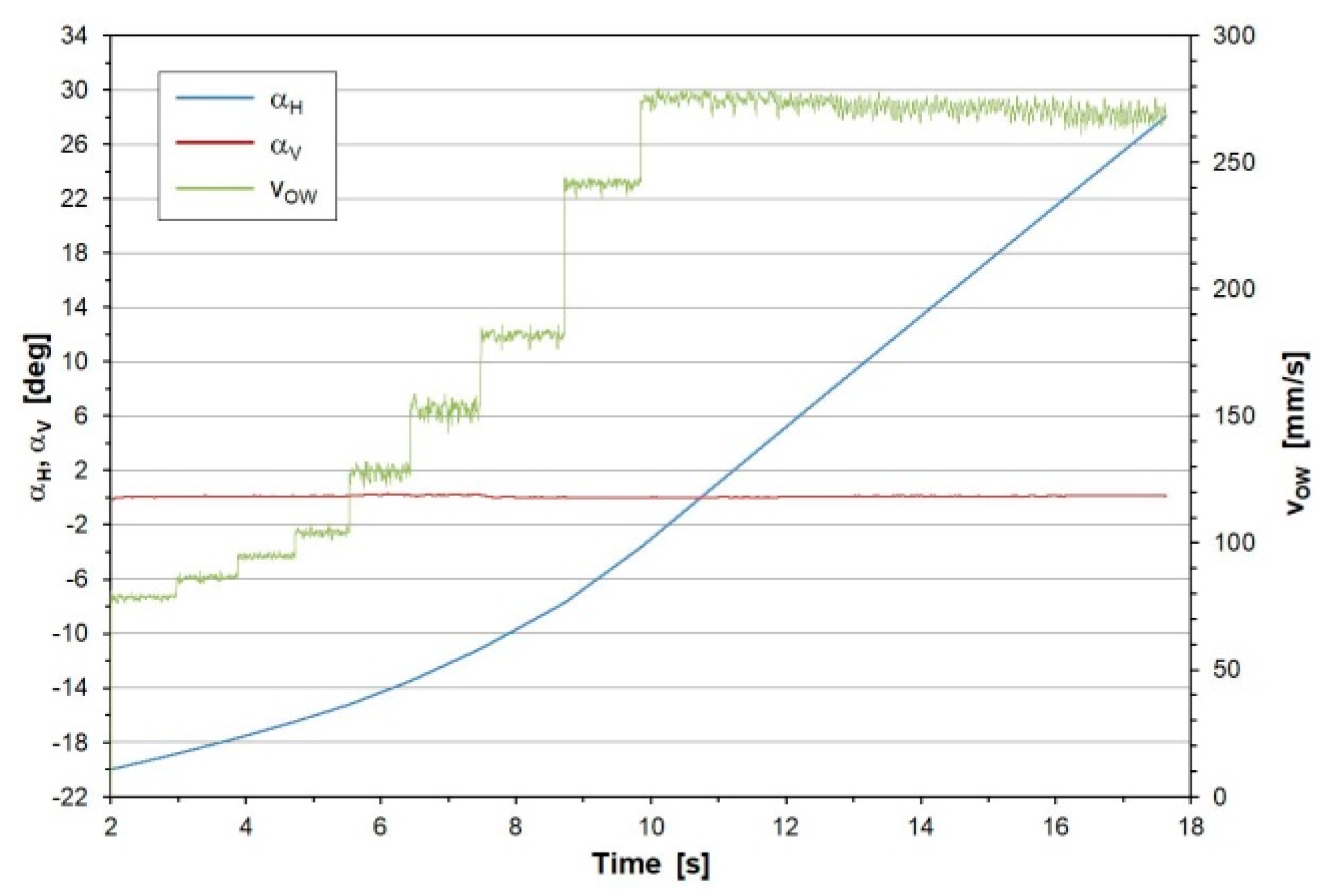
Figure 14). The cutting took 15.6 s, during which the cutting heads made totally 17 rotations, and the boom was rotated clockwise within the angle
αH from the initial value
= −20° to the final value
= +27° (
Figure 9, blue line). During the subsequent rotations of cutting heads, the setting system controlling the cutting process parameters determined the values of these parameters (
fREF,
kDO REF,
hREF), choosing the appropriate cases based on the dynamic load of the roadheader’s cutting system.
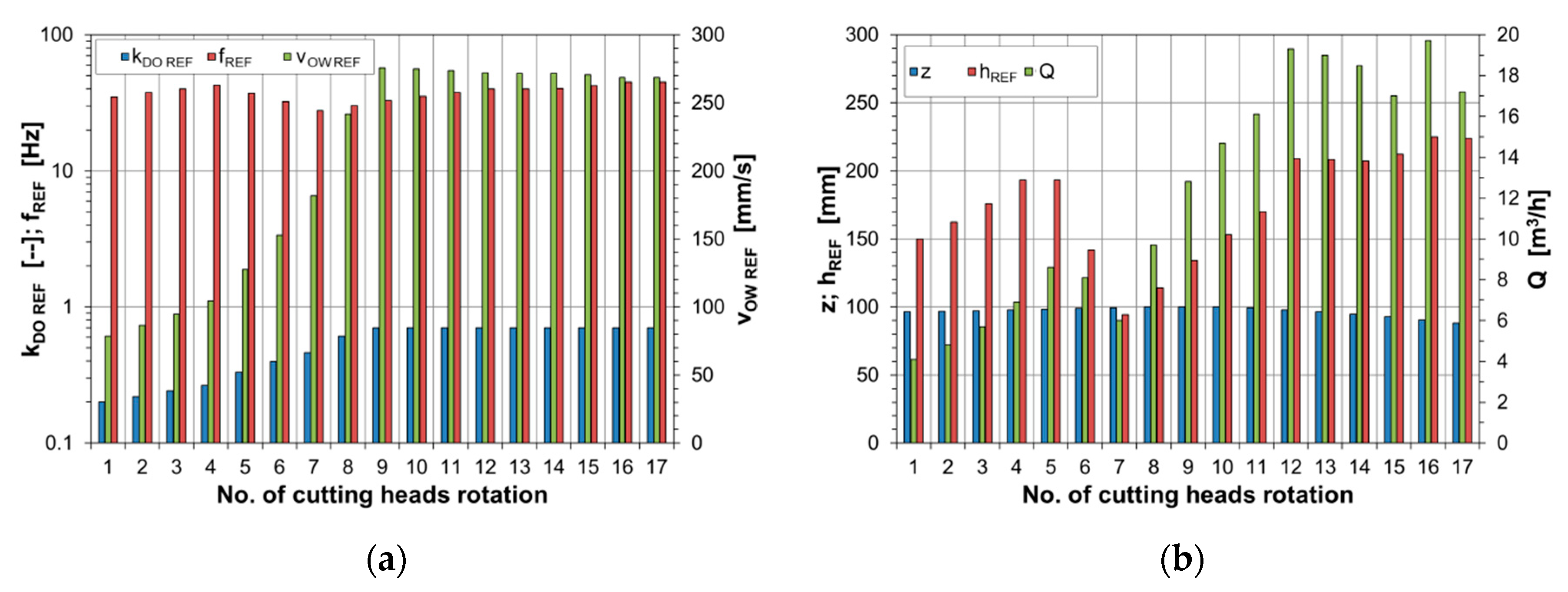
In the range of the low boom swinging speed (cutting head rotations 1–4), the setting system increased the boom swinging speed by increasing the opening coefficient value of the electrohydraulic valve to
kDO REF = 0.266 (
Figure 10, blue bars). Simultaneously, the angular speed of the cutting heads was increased by an increase in the frequency of the motor supply voltage in the cutting system to
fREF = 42.5 Hz (red bars). The cut height was also increased to
hREF = 192 mm (
Figure 10b, red bars). The setting system used the algorithm for determining the cutting process parameters for
Case 2 (
Table 3), as the average torque value on the output shaft of the cutting system motor was <0.8⋅
Tn and the number of exceedances of the set maximum value by instantaneous torque
NE was <500 (
Figure 11a).
In the range of the medium boom swinging speed (cutting head rotations 5 and 6), the setting system increased the boom swinging speed by increasing the opening coefficient value of the electrohydraulic valve to
kDO REF = 0.397. At the same time, it reduced the angular speed of the cutting heads by decreasing the frequency of the motor supply voltage up to
fREF = 32.5 Hz (
Figure 10a). It also reduced the cut height to
hREF = 94 mm (
Figure 10b). In this speed range
vOW, the dynamic loads of the roadheader’s cutting system were particularly high, and the setting system implemented the algorithm for
Case 4 (
Table 3). The instantaneous torque values on the motor shaft exceeded the set maximum value, as the adopted number of dynamic overloads (
kd = 2) was >500 (
NE > 500).
In the range of the high boom swinging speed (cutting head rotations 7–17), the aim was to achieve the highest possible efficiency with the low energy consumption during cutting. The setting system increased the boom swinging speed by setting, in the ninth rotation of cutting heads, the maximum value of the opening coefficient of the electrohydraulic valve (
kDO REF = 0.7) corresponding to the boom swinging speed
vOW of 270 mm/s. In addition, the angular speed of the cutting heads was gradually increased by an increase in the frequency of the supply voltage
fREF to 45 Hz. Due to the motor underload in the cutting system, the setting system also increased the height of cut
hREF to >200 mm. Furthermore, the average cutting efficiency
Q, which exceeded 17 m
3/h, was increasing (
Figure 10b).
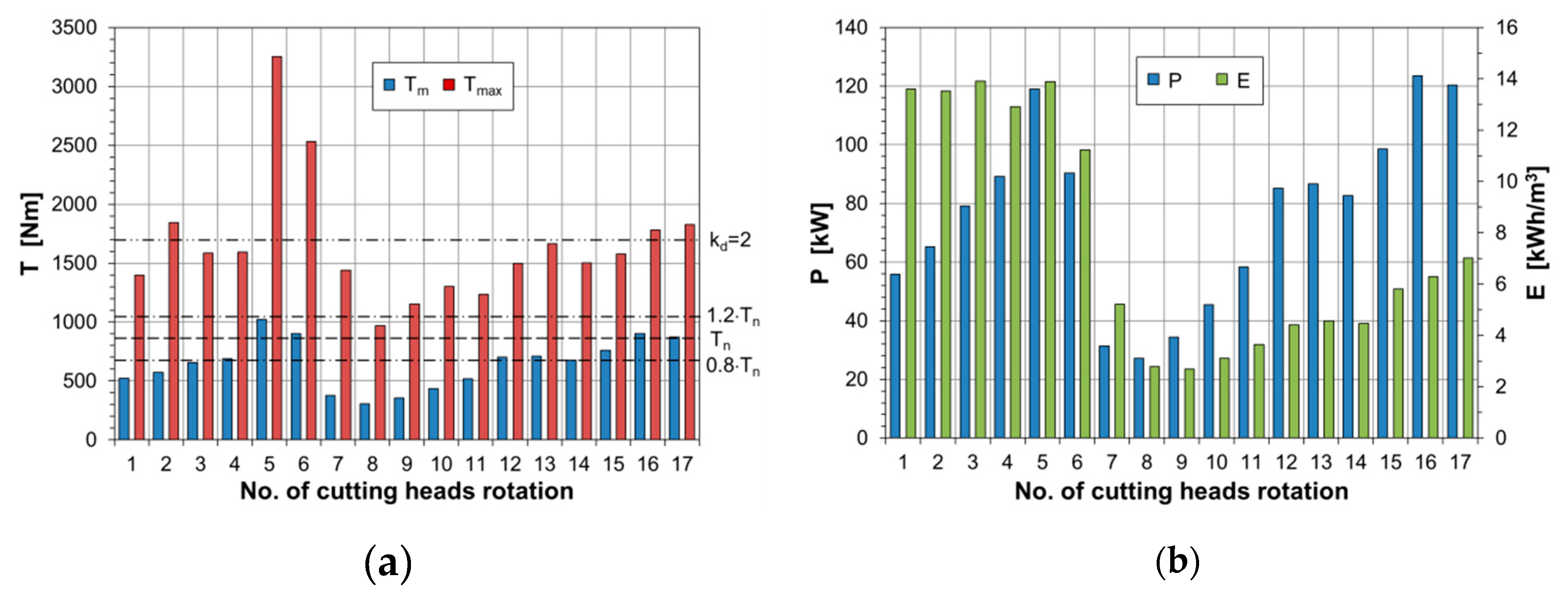
The mechanical power
P consumed by the cutting system (which is the product of the torque on the motor shaft and its angular speed) changed with changing the values of the cutting process parameters and the load on the cutting heads drive (
Figure 11b, blue bars). The power increased in the first two intervals of the boom swinging speed (cutting head rotations 1–6), reaching up to 120 kW, after which it started to decrease due to the reduction in the angular speed of the cutting heads and the cut height. In the range of the high boom swinging speed (cutting head rotations 7–17), the power gradually increased up to 120 kW. The energy consumption of cutting
E was high (14 kWh/m
3) in the initial period (cutting head rotations 1–6) due to the low cutting efficiency (
Figure 11b, green bars). In the range of the high boom swinging speed (cutting head rotations 7–17), the high cutting efficiency ensured the clear reduction of the energy consumption, which was at a low level, not exceeding 7 kWh/m
3. The low energy consumption by the cutting heads during mining was only apparent during the rotations 7–11. This resulted from the high underloading of the cutting heads drive. As mentioned earlier, the converter drive is characterized by low efficiency (a large proportion of constant losses), and hence should not be operated in such a state. Therefore,
Case 5 was not checked, and the energy consumption of mining is not considered to be minimal in this situation.
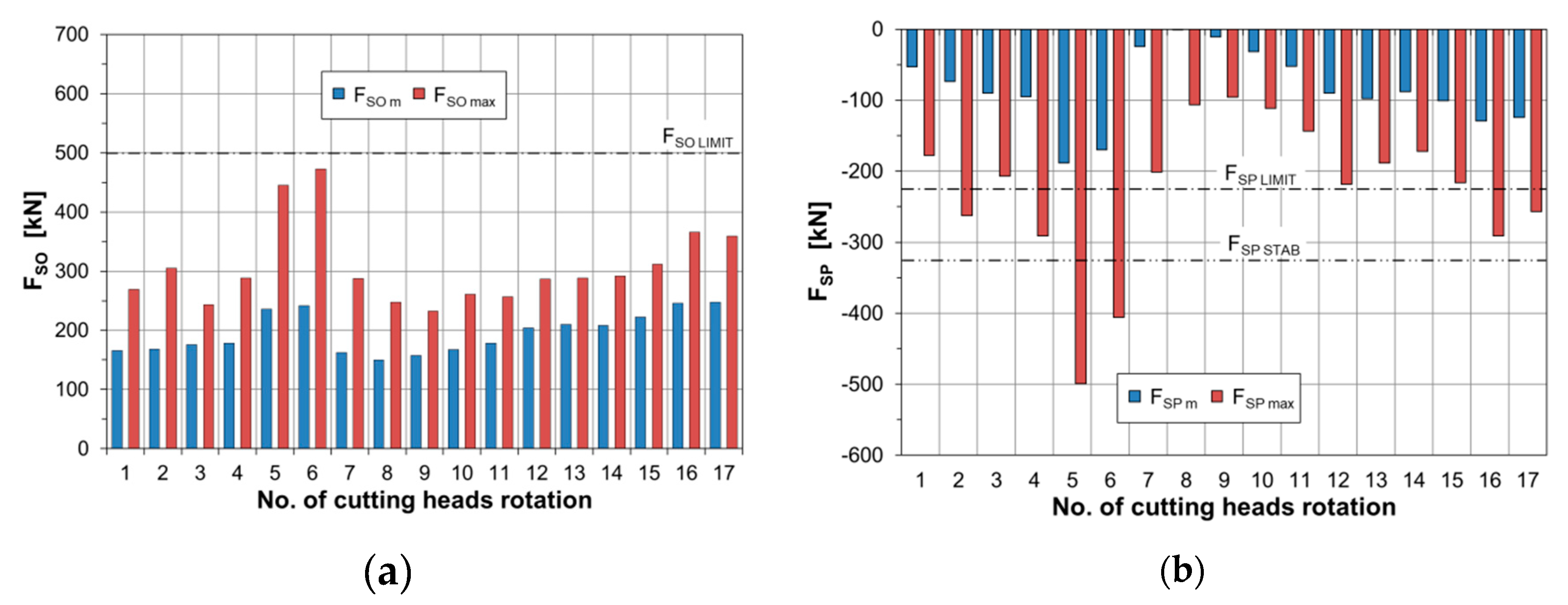
The average values (
FSO m) and peak values (
FSO max) of the dynamic load of the actuator in the boom swinging mechanism in a plane parallel to the floor were the highest in the range of the medium boom swinging speed (cutting head rotations 5 and 6;
Figure 12a). However, these values remained lower than the maximum value resulting from the maximum pressure in the hydraulic system of the tested roadheader (
FSO LIMIT). The peak and average dynamic load of the boom deflection actuators in a plane perpendicular to the floor (
FSP m and
FSP max) are negative (
Figure 12b). When making the lower cut, the resultant mining reaction acting on the boom is directed upwards, which causes tensile forces in these actuators. The average values determined during the subsequent rotations of the cutting heads did not exceed the one resulting from the maximum pressure in the hydraulic system (
FSP LIMIT), whereas the peak values exceeded this limit sporadically. When the dynamic load of the boom deflection actuators was analyzed, the possibility of the roadheader’s loss of stability was also checked. This situation is likely to occur when the load on these actuators exceeds the allowable limit (
FSP STAB) corresponding to the force acting on the boom at which the roadheader will reach its stability. During the fifth and sixth rotations of the cutting heads, the above-mentioned limit was exceeded. Nevertheless, this condition existed only for a short duration, and the roadheader did not lose its stability.
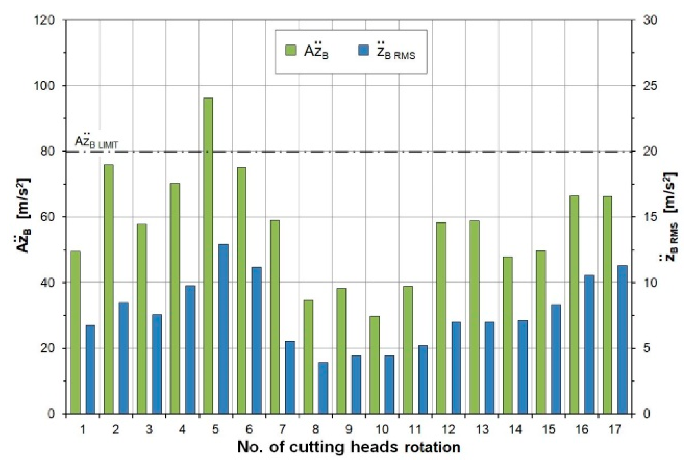
After the setting system optimized the values of all the cutting process parameters, the boom vibration intensity was below the acceptable level, which was confirmed by the amplitude and the RMS value of the boom transverse vibration acceleration, determined in the periods of subsequent rotations of the cutting heads (
Figure 13). As can be seen, only during the fifth rotation of the cutting heads, the amplitude of the vibration acceleration exceeded the accepted level (
). Therefore, it can be understood that the criterion of vibration reduction (third control criterion) was also met in the range of the high boom swinging speeds. In this range (cutting head rotations 8–17), the amplitude of the boom transverse vibration acceleration did not exceed 70 m/s
2 and the RMS value was <12 m/s
2.
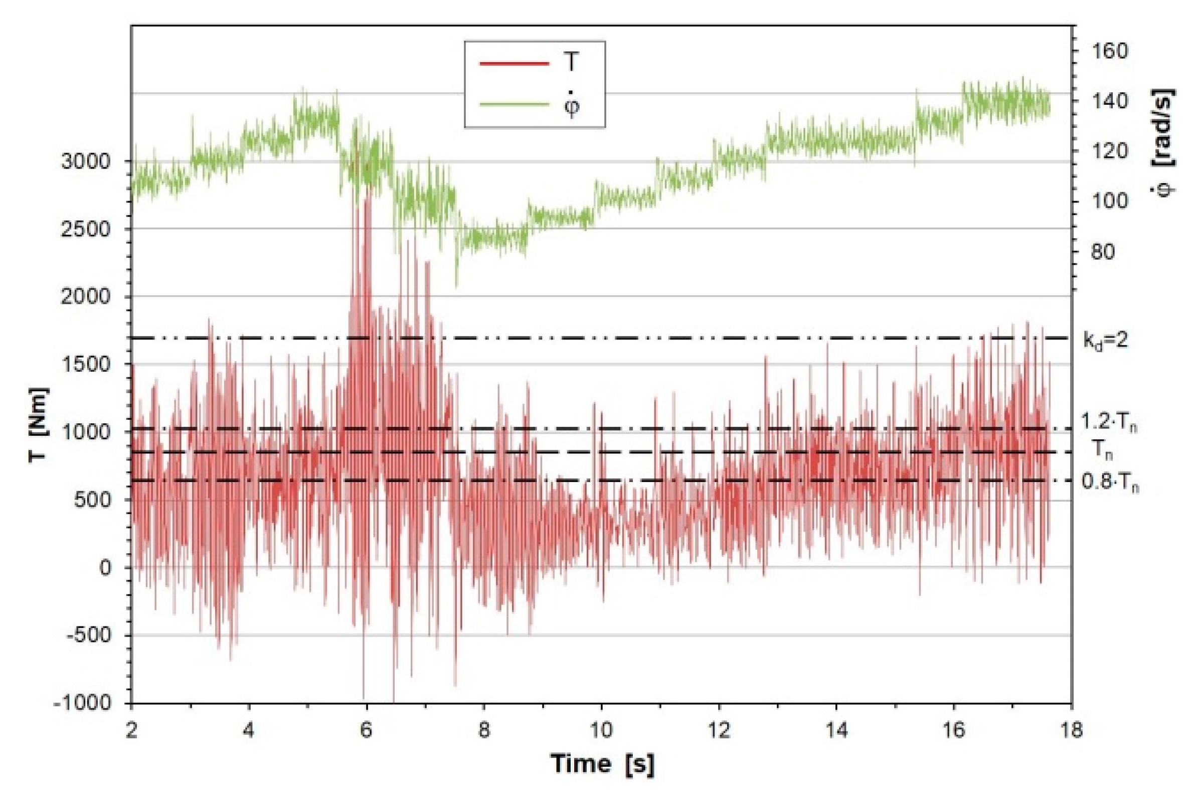
The time course of torque on the motor shaft in the cutting heads drive (
Figure 14) confirms that the most significant dynamic loads of the cutting system occurred in the range of the medium boom swinging speed, during the fifth and sixth rotations of the cutting heads. However, reducing the angular speed of the cutting heads while increasing the boom swinging speed allowed transitioning to the high boom swinging speed range. At its beginning, a clear reduction occurred in the dynamic load, due to a change in the values of the cutting process parameters in the subsequent rotations of the cutting heads. From the 13th second of the simulation, the setting system worked out the optimal values of the cutting process parameters due to the adopted control criteria.
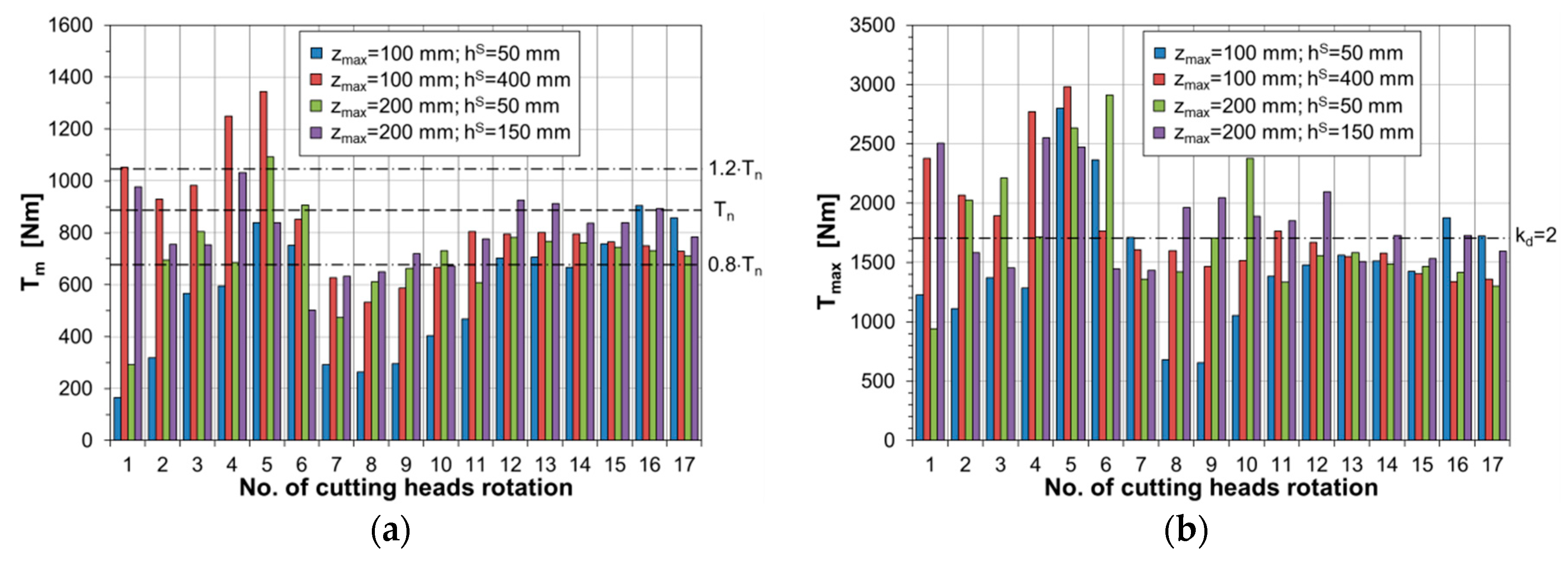
5. Influence of the Web of Cut and the Initial Cut Height
The web of cut and the initial cut height are treated as random variables. The former is determined by the amount of displacement of the entire machine to the heading face (for a roadheader equipped with a monolithic boom). In turn, when the roadheader is equipped with a telescopic boom, the web of cut is determined by the telescope’s extension. In both cases, the control of this parameter is associated with the necessity to determine the position of the roadheader relative to the heading face of the drilled excavation, which cannot be achieved without the use of positioning systems. The initial height of the cut performed is the result of moving up or down the cutting heads within one of the sidewalls of the roadway or tunnel. This displacement depends on the changes in the boom deflection angle in a plane perpendicular to the floor ΔαV. For manual and automatic control, the displacement of the cutting heads in a direction perpendicular to the floor may not be optimal for making the next cut.
While conducting computer tests, the behavior of the automatic control system was checked for various combinations of the values of these two cutting process parameters.
Figure 15,
Figure 16,
Figure 17,
Figure 18 and
Figure 19 show the results of the computer simulations for two maximum web of cut values (
zmax = 100 and 200 mm) and different initial cut heights
hS. The lower cut in rock with a uniaxial compressive strength
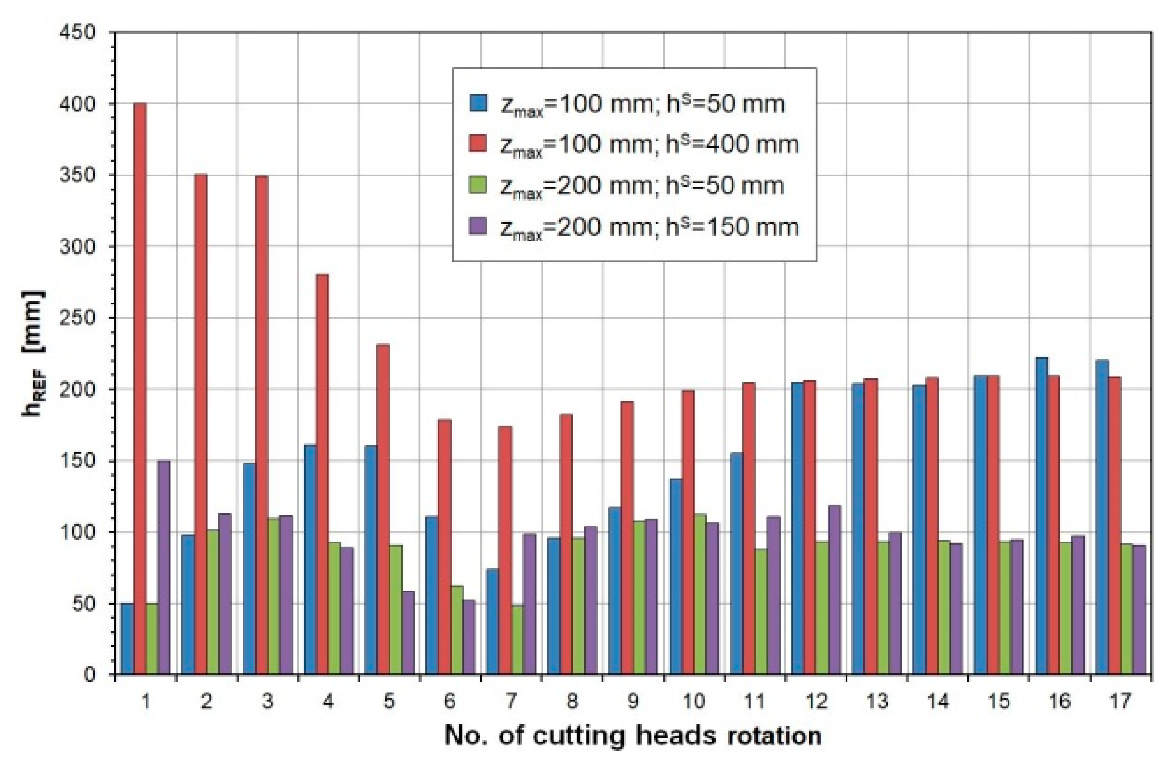
σc of 50 MPa is analyzed here. The setting system determined the values of the cutting process parameters by selecting the appropriate procedures based on the dynamic load of the roadheader’s cutting system, in subsequent rotations of the cutting heads (
Table 4). In the case when
hS = 50 mm, for
zmax = 200 mm, the setting system determined smaller cutting heights than for
zmax = 100 mm (
Figure 15, green and blue bars). In the range of the low swinging speed of the boom, the setting system increased the cut height for the web of cut
zmax = 200 mm and the initial cutting height
hS = 50 mm and decreased the cut height for
hS = 150 mm (violet bars). A similar effect was visible for the web of cut
zmax = 100 mm when cutting began at the cut height
hS = 400 mm (red bars). During the first six rotations of the cutting heads, the cut height was reduced more than twice. Due to the dynamic load of the cutting heads drive in this phase, for both the web of cut values considered, the lower limit of the initial cut heights was too small and the larger limit was too high. In the range of the medium boom swinging speed, the cut height decreased in all cases. By comparing the cuts with the same initial height (
hS = 50 mm), it can be seen that for the web of cut
zmax = 200 mm, the cut height determined by the setting system was half the size than for
zmax = 100 mm. In the range of the high boom swinging speed, starting from the eighth rotation, for cutting with
zmax = 200 mm, the cut height
h was at the level of 90–120 mm, while for cutting with
zmax = 100 mm the cut height was at the level of 200–220 mm (
Figure 15). It can be seen that the dynamic load of the roadheader depends not much on the web of cut or the cut height. Instead, it depends on the cut cross-sectional area, which results from the combination of the values of these two parameters.
The setting system controlling the cutting process parameters, and determining the appropriate values of these parameters (
fREF,
kDO REF,
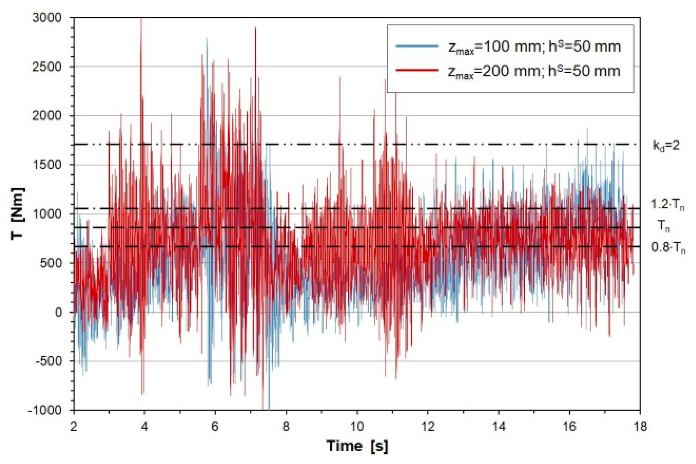
hREF) for the subsequent rotations of the cutting heads, also determines the course of the dynamic torque on the motor shaft in the drive of the cutting heads. The time series of this load in the subsequent rotations of the cutting heads for different webs of cut and the same initial cut height was similar (
Figure 16). This is due to the fact that the setting system compensated a larger web of cut with a reduced cut height, which made the cross-sectional area of both cuts to be at a similar level. The greatest variation in these waveforms occurred in the ranges of the low and medium boom swinging speed.
The average torque values on the motor shaft in the subsequent rotations of the cutting heads differed when cutting at different initial heights and webs of cut (
Figure 17a). This was especially noticeable in the range of the low boom swinging speed, during which the larger cross-section of the cut resulted in a higher load on the motor. In the range of the high boom swinging speed, the average values of the dynamic motor load in the cutting heads drive were equalized, almost reaching the nominal load value.
At the same initial cut height, the maximum values of motor torque for the web of cut
zmax = 200 mm reached a higher level than for
zmax = 100 mm, for most rotations of the cutting heads (
Figure 17b). Exceeding the set value of the maximum torque of the motor, determined by the number of dynamic overloads
kd = 2, with the number of instantaneous torque exceedances
NE being >500, caused the cutting parameters to be determined by the setting system for
Case 4. When
zmax = 100 mm, the dynamic overload occurred during the cutting head rotations 5 and 6–for
hS = 50 mm and during the rotations 1, 4, and 5 – for
hS = 400 mm (
Table 4). In turn, for the web of cut value
zmax = 200 mm, the dynamic overload occurred during the cutting head rotations 3, 5, 6, and 10 – for
hS = 50 mm and during the rotations 1, 4, 5, and 12—for
hS = 150 mm.
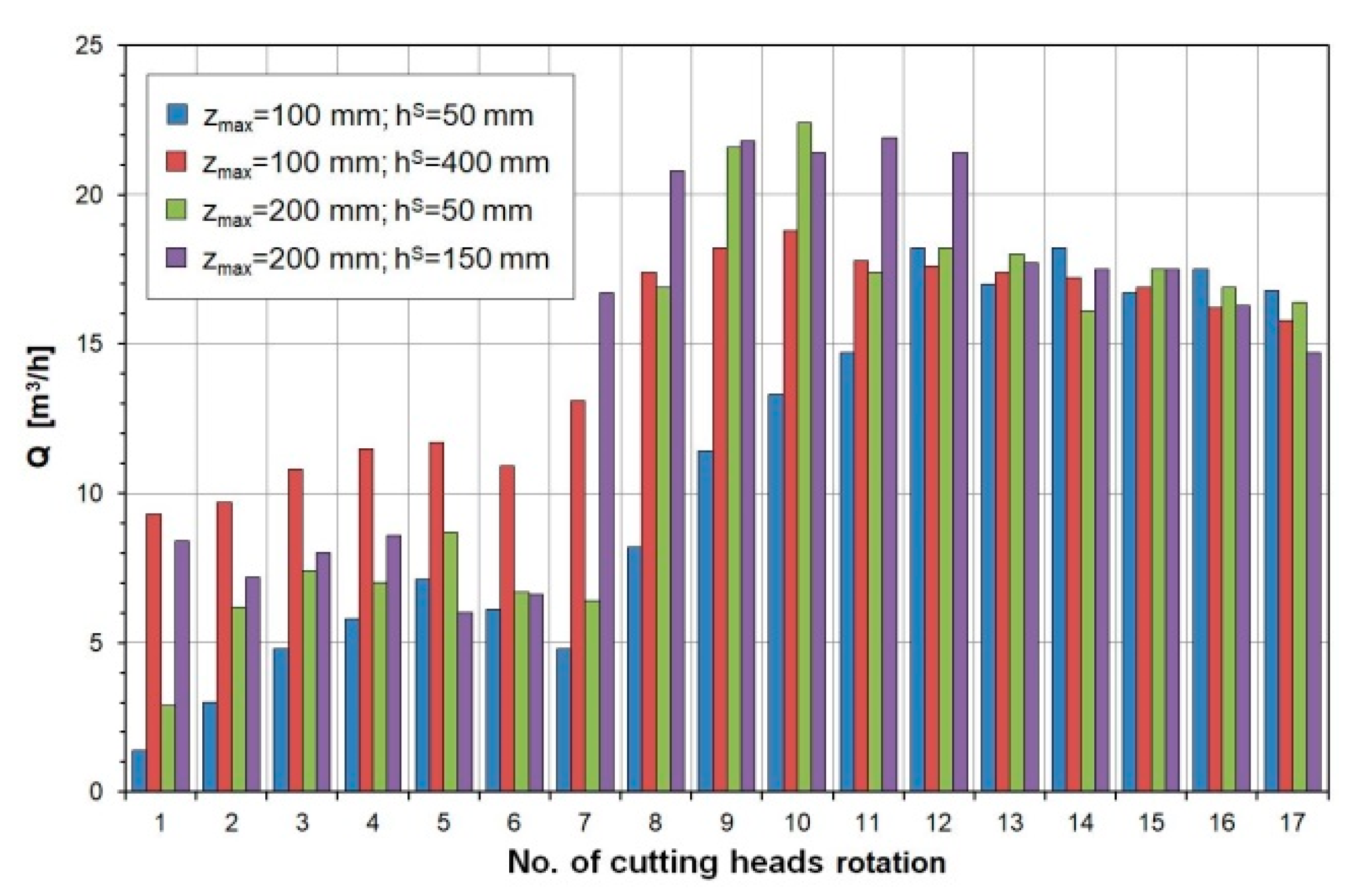
The larger cross-sectional area of the cut ensured a greater cutting efficiency (
Figure 18). This particularly concerned the range of the low boom swinging speed (cutting head rotations 1–4). After obtaining the maximum swinging speed of the boom and stabilizing the height of cuts, the cutting efficiency was evened out by reaching the level of
Q = 15–22 m
3/h (cutting head rotations 12–17). The average cutting efficiency determined for the entire cutting increased with the increase in the web of cut and initial cut height, amounting to:
Qm = 10.9 m3/h – for zmax = 100 mm and hS = 50 mm,
Qm = 14.7 m3/h – for zmax = 100 mm and hS = 400 mm,
Qm = 13.3 m3/h – for zmax = 200 mm and hS = 50 mm, and
Qm = 14.9 m3/h – for zmax = 200 mm and hS = 150 mm.
In three of the four cases analyzed, the average cutting efficiency obtained over the entire length of the cut was quite similar. An exception was when the cutting was simulated with the initial height hS = 50 mm at the web of cut zmax = 100 mm. This effect was the result of lower efficiency in the first phase of the cutting process, during the acceleration of the cutting heads to the maximum movement speed.
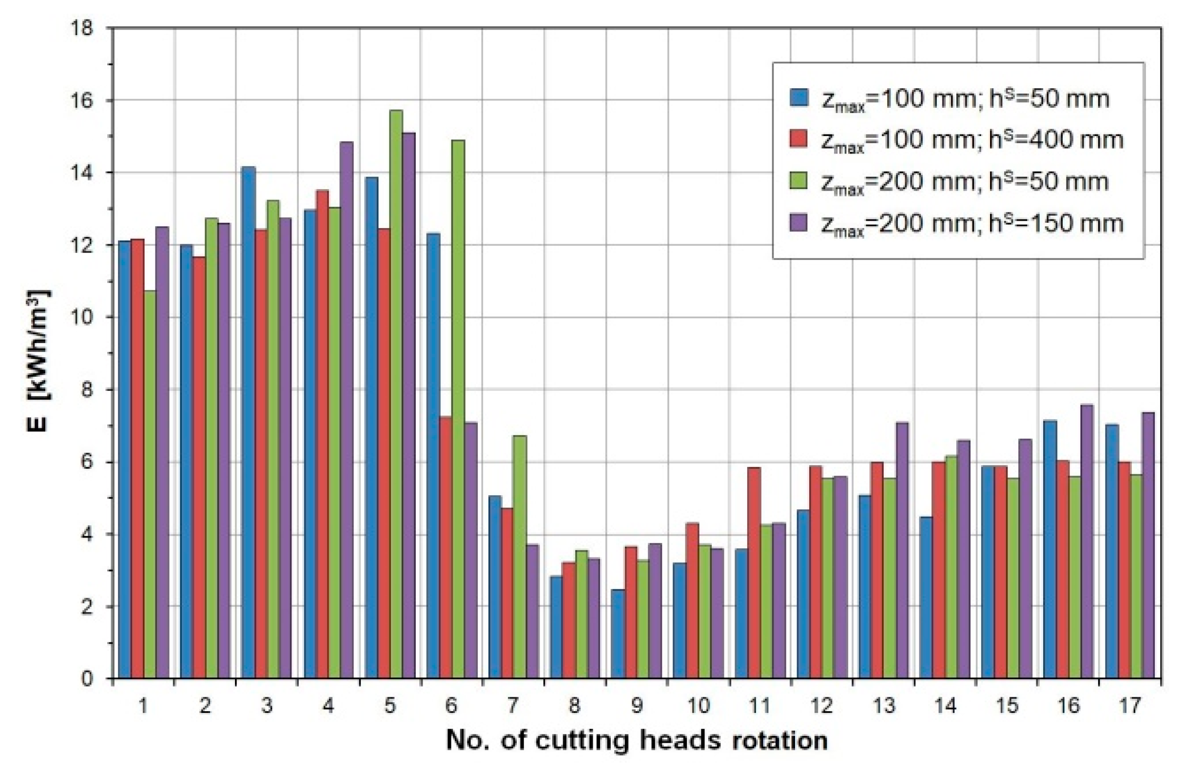
The course of energy consumption in the subsequent rotations of the cutting heads for all the analysed webs of cut and initial cut heights was quite similar, despite the different efficiency (
Figure 19). In the initial phase (cutting head rotations 1–6), the energy consumption of mining reached high values (
E = 12–16 kWh/m
3) due to the low efficiency of cutting. The high cutting efficiency achieved in the range of high boom swinging speed (rotations 10–17) ensured that the energy consumption was relatively low, below
E = 8 kWh/m
3. Similar to the previous case, during the rotation of the cutting heads 7–11, the motor in the cutting heads drive was underloaded (
Case 2). Therefore, the energy consumption of mining (calculated based on mechanical power) was unreliable, and so it was not taken into account in assessing whether the criterion for minimizing the mining energy consumption (fourth criterion of automatic control) was fulfilled.
6. Conclusions
The selected results of the extensive simulation tests presented in this paper formed the basis for assessing the operation of the automatic control system for the rock mining process with various mechanical properties by a roadheader. Furthermore, they allowed determining the structure of the automatic control system and its parameterization.
While performing computer tests, the usefulness of the developed algorithm for automatic control of the cutting process, with respect to obtaining optimal values of the process parameters in dynamically changing conditions, was analyzed. An essential element of the automatic control system is the setting system, the task of which is to correct the values of three cutting process parameters depending on the course of controlled quantity (dynamic load of the motor in the drive of cutting heads). It should be emphasized that these machines are a problematic object of automation. On the one hand, the automatic control system should work fast, as the cutting process is short during the subsequent cuts. The time of making a single cut (from one sidewall of the excavation to the other) usually does not exceed 20–30 s (in the examples cited, the time of simulated cutting while making a cut of around 3 m was not >16 s). On the other hand, very fast operation of the automatic control system is undesirable. The dynamic properties of the control object, the characteristics of its drives, and the nature of the working process indicate that rapid changes (corrections) in the parameters of this process are pointless. Identification of the tested object showed that the converter drive of the cutting heads is the regulation object of an oscillatory nature, and the hydraulic drive of the boom deflecting in a plane perpendicular to the floor is the control object of an “integrating with a time delay” nature. These cannot be put into practice by the drives but can serve as a source of additional excitation of harmful vibrations. Therefore, a trade-off between the control quality and the control speed is required.
The tests carried out on a real object (R-130 roadheader from Famur SA) in laboratory conditions (on a semi-industrial scale), while mining a cement–sand block with a layered structure, confirmed the effectiveness of the developed automatic control algorithm. Optimization of the cutting process parameters seems to be possible due to the adopted objective functions. It should be emphasized that the benefits obtained during these tests with the application of the developed solution were higher than that initially expected. Compared to manual control, the automatic control helped in achieving a much higher mining efficiency, better utilization of the cutting heads drive power, and a significantly higher (up to 50%) reduction of cutting energy consumption. In addition, the reduction in cutting energy consumption was accompanied by an improvement in the roadheader’s dynamic state (reduction of dynamic loads and vibrations in the structural nodes of the roadheader). The selected test results conducted on a real object can be read in some publications [
2,
26].
The development of an effective system for the automatic control of the cutting process parameters is an essential step on the road towards the robotization of roadheaders, which will enable full autonomy of this type of mining machinery. However, the developed control system must be integrated with other autonomous machine systems, such as the roadheader monitoring system, the positioning system, or the planning system for the movement trajectory of the cutting heads on the heading face [
33]. The presented solution should also contribute to increased durability and reliability as well as reducing the operating costs of roadheaders.


